EP3312947B1 - Transmission line, in particular of rigid type and for radiofrequency power application - Google Patents
Transmission line, in particular of rigid type and for radiofrequency power application Download PDFInfo
- Publication number
- EP3312947B1 EP3312947B1 EP17197464.5A EP17197464A EP3312947B1 EP 3312947 B1 EP3312947 B1 EP 3312947B1 EP 17197464 A EP17197464 A EP 17197464A EP 3312947 B1 EP3312947 B1 EP 3312947B1
- Authority
- EP
- European Patent Office
- Prior art keywords
- conductor
- connection element
- transmission line
- tubular
- tract
- Prior art date
- Legal status (The legal status is an assumption and is not a legal conclusion. Google has not performed a legal analysis and makes no representation as to the accuracy of the status listed.)
- Active
Links
Images


Classifications
-
- H—ELECTRICITY
- H01—ELECTRIC ELEMENTS
- H01R—ELECTRICALLY-CONDUCTIVE CONNECTIONS; STRUCTURAL ASSOCIATIONS OF A PLURALITY OF MUTUALLY-INSULATED ELECTRICAL CONNECTING ELEMENTS; COUPLING DEVICES; CURRENT COLLECTORS
- H01R24/00—Two-part coupling devices, or either of their cooperating parts, characterised by their overall structure
- H01R24/38—Two-part coupling devices, or either of their cooperating parts, characterised by their overall structure having concentrically or coaxially arranged contacts
- H01R24/40—Two-part coupling devices, or either of their cooperating parts, characterised by their overall structure having concentrically or coaxially arranged contacts specially adapted for high frequency
- H01R24/56—Two-part coupling devices, or either of their cooperating parts, characterised by their overall structure having concentrically or coaxially arranged contacts specially adapted for high frequency specially adapted to a specific shape of cables, e.g. corrugated cables, twisted pair cables, cables with two screens or hollow cables
- H01R24/566—Hollow cables
-
- H—ELECTRICITY
- H01—ELECTRIC ELEMENTS
- H01R—ELECTRICALLY-CONDUCTIVE CONNECTIONS; STRUCTURAL ASSOCIATIONS OF A PLURALITY OF MUTUALLY-INSULATED ELECTRICAL CONNECTING ELEMENTS; COUPLING DEVICES; CURRENT COLLECTORS
- H01R13/00—Details of coupling devices of the kinds covered by groups H01R12/70 or H01R24/00 - H01R33/00
- H01R13/62—Means for facilitating engagement or disengagement of coupling parts or for holding them in engagement
- H01R13/627—Snap or like fastening
-
- H—ELECTRICITY
- H01—ELECTRIC ELEMENTS
- H01P—WAVEGUIDES; RESONATORS, LINES, OR OTHER DEVICES OF THE WAVEGUIDE TYPE
- H01P3/00—Waveguides; Transmission lines of the waveguide type
- H01P3/02—Waveguides; Transmission lines of the waveguide type with two longitudinal conductors
- H01P3/06—Coaxial lines
-
- H—ELECTRICITY
- H01—ELECTRIC ELEMENTS
- H01P—WAVEGUIDES; RESONATORS, LINES, OR OTHER DEVICES OF THE WAVEGUIDE TYPE
- H01P5/00—Coupling devices of the waveguide type
- H01P5/02—Coupling devices of the waveguide type with invariable factor of coupling
- H01P5/022—Transitions between lines of the same kind and shape, but with different dimensions
- H01P5/026—Transitions between lines of the same kind and shape, but with different dimensions between coaxial lines
-
- H—ELECTRICITY
- H01—ELECTRIC ELEMENTS
- H01R—ELECTRICALLY-CONDUCTIVE CONNECTIONS; STRUCTURAL ASSOCIATIONS OF A PLURALITY OF MUTUALLY-INSULATED ELECTRICAL CONNECTING ELEMENTS; COUPLING DEVICES; CURRENT COLLECTORS
- H01R24/00—Two-part coupling devices, or either of their cooperating parts, characterised by their overall structure
- H01R24/38—Two-part coupling devices, or either of their cooperating parts, characterised by their overall structure having concentrically or coaxially arranged contacts
- H01R24/40—Two-part coupling devices, or either of their cooperating parts, characterised by their overall structure having concentrically or coaxially arranged contacts specially adapted for high frequency
- H01R24/42—Two-part coupling devices, or either of their cooperating parts, characterised by their overall structure having concentrically or coaxially arranged contacts specially adapted for high frequency comprising impedance matching means or electrical components, e.g. filters or switches
-
- H—ELECTRICITY
- H01—ELECTRIC ELEMENTS
- H01R—ELECTRICALLY-CONDUCTIVE CONNECTIONS; STRUCTURAL ASSOCIATIONS OF A PLURALITY OF MUTUALLY-INSULATED ELECTRICAL CONNECTING ELEMENTS; COUPLING DEVICES; CURRENT COLLECTORS
- H01R24/00—Two-part coupling devices, or either of their cooperating parts, characterised by their overall structure
- H01R24/38—Two-part coupling devices, or either of their cooperating parts, characterised by their overall structure having concentrically or coaxially arranged contacts
- H01R24/40—Two-part coupling devices, or either of their cooperating parts, characterised by their overall structure having concentrically or coaxially arranged contacts specially adapted for high frequency
- H01R24/56—Two-part coupling devices, or either of their cooperating parts, characterised by their overall structure having concentrically or coaxially arranged contacts specially adapted for high frequency specially adapted to a specific shape of cables, e.g. corrugated cables, twisted pair cables, cables with two screens or hollow cables
-
- H—ELECTRICITY
- H01—ELECTRIC ELEMENTS
- H01R—ELECTRICALLY-CONDUCTIVE CONNECTIONS; STRUCTURAL ASSOCIATIONS OF A PLURALITY OF MUTUALLY-INSULATED ELECTRICAL CONNECTING ELEMENTS; COUPLING DEVICES; CURRENT COLLECTORS
- H01R2103/00—Two poles
Definitions
- the present invention relates to a transmission line, in particular of the rigid type and for a radiofrequency power application, according to claim 1.
- a transmission line in particular of the rigid type and for radiofrequency power applications, is so designed as to comprise a first conductor (also known as “outer conductor”) having a tubular shape, a second conductor (also known as “inner conductor”) concentrically and coaxially positioned inside said first conductor, and a dielectric positioned between the first conductor (outer conductor) and the second conductor (inner conductor).
- the dielectric positioned between the first conductor and the second conductor may consist of air or gas.
- the junction connector is so designed as to comprise a body adapted to be coupled to a terminal tract of the outer conductor, and comprises at least one connection element adapted to be inserted, at least partially, into a seat formed in one end of the inner conductor; in its turn, the connection element comprises a substantially tubular portion from which a plurality of elastic tabs extend.
- the junction connector is so designed as to comprise a casing typically having a cylindrical (sleeve-like) shape, in particular said casing having an inside diameter that makes the ends thereof suitable for being coupled to one end of the outer conductor.
- said casing is typically made of metallic materials.
- the connector casing is associated with a body (also referred to as “spacer” or “rigid centralizer”) having a substantially discoid (flange-like) shape, which allows the connection element to be positioned coaxially within the casing and the inner connection element to be insulated from said casing.
- Said body or spacer is preferably made of non-conductive material, in particular plastic material (e.g. polytetrafluoroethylene, also known as "PTFE”, i.e. a polymer of tetrafluoroethylene commercially known as TEFLON® or ALGOFLON® or HOSTAFLON® or FLUON®).
- plastic material e.g. polytetrafluoroethylene, also known as "PTFE”, i.e. a polymer of tetrafluoroethylene commercially known as TEFLON® or ALGOFLON® or HOSTAFLON® or FLUON®.
- the junction connector may be so designed as to comprise only the substantially discoid (flange-like) body suitable for being coupled to a terminal tract of the outer conductor.
- a distinct connection element extends which is adapted to be coupled to the corresponding end of the inner conductor of the rigid line, said connection element comprising a substantially tubular portion associated with a plurality of elastic tabs.
- the discoid connector allows the connection element to be positioned coaxially within the connector, and the inner conductor to be insulated from the outer conductor.
- the discoid body is preferably made of plastic material, e.g.
- polytetrafluoroethylene also known as "PTFE”, i.e. a polymer of tetrafluoroethylene commercially known as TEFLON® or ALGOFLON® or HOSTAFLON® or FLUON®
- PTFE polytetrafluoroethylene
- connection element and the inner conductor are coupled to each other by inserting the connection element into the end of the inner conductor, this insertion being typically achieved through a substantially linear movement; during this movement, the elastic tabs of the connection element are forced to bend (so as to facilitate the insertion of said connection element into the end of the inner conductor) and then flex towards the inner surface of said inner conductor, thus establishing an optimal connection between the two components.
- connection element is so designed as to ensure both elasticity, due to the non-continuous profile obtained by means of the plurality of elastic tabs, and adequate tightness, due to the fact that the diameter of the connection element is slightly smaller than that of the inner conductor.
- a current I is made to flow along said inner conductor.
- Said current I is surrounded by a magnetic field B which, as it reaches the outer conductor, induces therein an induced current opposite to the cause that generated it. If the difference between the diameters of the inner conductor and outer conductor is small, the current induced in the outer conductor will be offset by 180° relative to the current flowing along the inner conductor. Equal and opposite currents cancel each other out and produce no radiation. The above does not occur when such high frequencies are reached that reduce the ratio between the wavelength of the applied signal and the difference between the radii of the two conductors.
- Said limitation of the transmissible power is not due to the fact that the ordinary sections of the transmission line cannot carry the power being considered, but to the necessity for preventing any potential junction overheating; exceeding this upper limit will lead to destruction of the junction itself or of an adjacent tract of the rigid transmission line.
- this frame it is the main object of the present invention to provide a transmission line, in particular of the rigid type and for a radiofrequency power application, which is so designed as to allow overcoming the drawbacks of prior-art transmission lines.
- reference numeral 1 designates as a whole a transmission line, in particular of the rigid type and for a radiofrequency power application, in accordance with the present invention.
- the transmission line 1 comprises, as is known in the art, a first conductor 10 (which can be defined as “outer conductor”) having a tubular shape, a second conductor 20 (which can be defined as “inner conductor”), concentrically and coaxially positioned inside said first conductor 10, and a dielectric 30 positioned between the first conductor 10 and the second conductor 20.
- the first conductor 10 and the second conductor 20 are made of a material (e.g. copper or aluminium) having a very low resistivity value, whereas said dielectric 30 preferably consists of air; this provision allows for fast assembly of the rigid transmission line 1 in the place where the system is located, without incurring the typical risks deriving from the use of a dielectric consisting of gas.
- a material e.g. copper or aluminium
- said dielectric 30 preferably consists of air
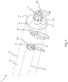
- FIG. 1 the first conductor 10 is represented as if it were transparent; however, such a representation of the first conductor 10 is merely aimed at showing the components that are present inside.
- the transmission line 1 further comprises a connector (designated as a whole by reference numeral 40 in the annexed drawings) equipped with a body 40A adapted to be coupled to a terminal tract 11 of the first conductor 10.
- a connector designated as a whole by reference numeral 40 in the annexed drawings
- body 40A adapted to be coupled to a terminal tract 11 of the first conductor 10.
- the body 40A has a substantially discoid shape suitable for being coupled to a terminal tract 11 of the first conductor 10.
- the body 40A is at least partially inserted into said terminal tract 11 of the tubular first conductor 10, the dimensions of the body 40A being slightly smaller than the internal dimensions of the terminal tract 11 of said tubular first conductor 10; as a result, the body 40A of the connector 40 is secured by interference to the inner walls of the terminal tract 11 of said tubular first conductor 10.
- the coupling between the terminal tract 11 of the first conductor 10 and the body 40A of the connector 40 may also be different than shown in Fig. 1 ; merely by way of example, said coupling may be effected by screwing the body 40A of the connector into the terminal tract 11 of the first conductor 10.
- the body 40A of the connector 40 is made of non-conductive material, in particular plastic material (e.g., polytetrafluoroethylene, also known as "PTFE").
- plastic material e.g., polytetrafluoroethylene, also known as "PTFE”
- the connector 40 comprises at least one first connection element (designated as a whole by reference numeral 41 in the annexed drawings) adapted to be inserted, at least partially, into a seat 21A formed in one end 21 of the second conductor 20, said at least one first connection element 41 comprising a substantially tubular first portion 41A from which a plurality of first elastic tabs 41B extend.
- first connection element designated as a whole by reference numeral 41 in the annexed drawings
- the first tabs 41B allow to confer an adequate elasticity to the first connection element 41, since they allow said connection element 41 to be realized with a non-continuous profile.
- the portion 41A and/or each first tab 41B of the first connection element 41 have straight tracts joined by one or more curved tracts, so as to have one or more narrower sections adapted to facilitate the insertion of the first connection element 41 into said seat 21A formed in one end 21 of the second conductor 20.
- the second conductor 20 may consist of either a tubular element or a solid bar.
- the seat 21A substantially corresponds to the final tract of the tubular element; in the latter case (i.e. when the second conductor 20 consists of a solid bar), the seat 21A is formed or milled in the end 21 of the second conductor 20.
- the connector 40 comprises a pair of first connection elements 41 extending in opposite directions from the body 40A of the connector 40 (in particular, said pair of first connection elements 41 extend in opposite directions from each one of the substantially flat faces of the body 40A having a substantially discoid shape, as shown in the annexed drawings), so that each one of the first connection elements 41 can fit into respective seats 21A formed in the ends 21 of two different second conductors 20 belonging to two different sections of a transmission line 1; it should be noted that said pair of first connection elements 41 may also be made as one piece, particularly by making a single tubular portion 41A from which the first tabs 41B extend in opposite directions.
- the connector 40 can be realized to include a casing (not shown in the annexed drawings) having a substantially cylindrical (sleeve-like) shape, in particular made of metallic material, wherein said casing encloses the body 40A (which can also be defined as spacer or rigid centralizer, since it performs such functions), which allows at least one first connection element 41 to be coaxially positioned and insulated inside the substantially cylindrical body and said at least one first connection element 41.
- the body 40A is made of non-conductive material, in particular plastic material (e.g. polytetrafluoroethylene, also known as "PTFE").
- the connector 40 comprises at least one first connection element 41 adapted to be inserted, at least partially, into the seat 21A formed in the end 21 of the second conductor 20, in particular said at least one first connection element 41 comprising a substantially tubular first portion 41A from which a plurality of first elastic tabs 41B extend.
- the substantially cylindrical casing of the connector 40 is at least partially slipped over the outside of the terminal tract 11 of the tubular first conductor 10, the dimensions of said casing being slightly greater than the outer dimensions of the terminal tract 11 of said tubular first conductor 10.
- the second conductor 20 comprises a second connection element 22 at least partially positioned in said seat 21A, said second connection element 22 being adapted to be coupled to the first connection element 41 by inserting it into a cavity 41C of said first connection element 41; in particular, the shape of said cavity 41C is substantially tubular.
- the second connection element 22 has a shape substantially corresponding to that of the first connection element 41 and smaller dimensions than said first connection element 41, so that it can be inserted into the cavity 41C (which is substantially tubular in shape) of the first connection element 41 with optimal contact between the two components.
- the second connection element 22 comprises a substantially tubular tract 22A from which a plurality of second tabs 22B extend.
- the second tabs 22B confer adequate elasticity on the second connection element 22, since they allow said second connection element 22 to be realized with a non-continuous profile.
- each second tab 22B has/have straight tracts joined by one or more curved tracts, so that said second connection element 22A comprises one or more narrower sections that facilitate the insertion of the second connection element 22 (in particular, the second tabs 22B and the tract 22A) into said cavity 41C of the first connection element 41.
- the second conductor 20 is represented as having both ends 21 so realized as to comprise a respective second connection element 22 made in accordance with the provisions of the present invention; it is however clear that the second conductor 20 may alternatively have only one of the two ends 21 realized to include said second connection element 22.
- the second conductor 20 may consist of either a tubular element or a solid bar.
- the second connection element 22 may consist of a separate element that can be at least partially inserted into the seat 21A of the second conductor 20, wherein said seat 21A substantially corresponds to the final tract of the tubular element.
- the seat 21A and the second connection element 22 may be made either as described above or by appropriately machining the end 21 of the second conductor 20; in substance, when the second conductor 20 is a solid bar, the seat 21A and the second connection element 22 may also be substantially formed in the end 21 of the second conductor 20.
- connection element 22 allows realizing a transmission line 1, in particular of the rigid type and for a radiofrequency power application, in such a way as to allow overcoming the drawbacks of prior-art transmission lines.
- the second connection element 22 allows realizing the transmission line 1 in such a way as to make it possible to increase the transmissible power as a function of frequency, and hence of the maximum sizes of the conductors, while at the same time preventing the junction of said transmission line from suffering from potential overheating, since said second connection element 22 ensures effective dissipation of the heat generated in the transmission line 1 following an increase in transmissible power, the dimensions being equal, in particular of the heat generated at a junction of said transmission line 1.
- connection element 22 allows for a significant increase in the contact surface between the first connection element 41 and the second conductor 20; in fact, due to the provision of the second connection element 22, the first connection element 41 is in contact with the inner walls of the seat 21A and also with the outer walls of said second connection element 22 (in particular, with the outer walls of the second tabs 22B).
- the provision of the second connection element 22 according to the present invention allows decreasing the size of the second conductor 20 and of the first connection element 41 (which must be inserted into the seat 21A) in order to increase the frequency and transmissible power, while at the same time avoiding the junction overheating problems that are known to be suffered by the prior art.
- the second connection element 22 comprises a thrust element (not shown in the annexed drawings, since said thrust element is preferably positioned within the space defined by the second tabs 22B of the second connection element 22) adapted to expand as the first connection element 41 and the second conductor 20 are coupled together; as a consequence, said thrust element allows exerting more pressure from within the second connection element 22, which will then press against the first connection element 41, which in turn will exert more pressure on the inner walls of the seat 21A.
- a thrust element (not shown in the annexed drawings, since said thrust element is preferably positioned within the space defined by the second tabs 22B of the second connection element 22) adapted to expand as the first connection element 41 and the second conductor 20 are coupled together; as a consequence, said thrust element allows exerting more pressure from within the second connection element 22, which will then press against the first connection element 41, which in turn will exert more pressure on the inner walls of the seat 21A.
- said thrust element may consist of an element having a substantially truncated-cone shape, which, in an idle condition, is partially inserted in the second connection element 22 with its major base facing towards the first connection element 41.
- the major base of the truncated cone abuts on the inside of the first connection element 41; as the pressure necessary for causing the second conductor 20 (inner conductor) to come in abutment is exerted, the truncated cone will translate in the second connection element 22, thereby exerting pressure from within and improving the contact between the second tabs 22B of the second connection element 22 and the first connection element 41.
- Fig. 3 shows a longitudinal sectional view of a first variant of the transmission line 1 according to the present invention.
- the second conductor 20 has a variable profile along its longitudinal development, so as to constitute an impedance transformer.
- variable profile is obtained by means of a second conductor 20 comprising at least two portions (in Figures 3 and 4 , references P1, P2, P3, P4, Pn designate a plurality of said portions) having different outside diameters in a cross-sectional view relative to the longitudinal development of said first conductor 10 and second conductor 20; it should be noted that, in this variant, the outside diameter of the ends 21 of the second conductor 20 is such as to allow obtaining an impedance equal to the nominal one of the transmission line 1.
- Fig. 4 shows a longitudinal sectional view of a second variant of the transmission line 1 according to the present invention.
- the transmission line 1 comprises at least one tract of a second dielectric 31 made of a different material than the dielectric 30 positioned between the first conductor 10 and the second conductor, in particular said second dielectric 31 being of the solid type and/or being made of a material having a higher thermal exchange coefficient than the dielectric 30 (which typically consists of air).
- the tract of the second conductor 20 that is surrounded by the solid second dielectric 31 is so sized as to have a lower impedance than the contiguous tracts (said contiguous tracts being, in the representation of Fig. 4 , the ones designated by references P2 and P4) of the second conductor 20 that are in contact with the dielectric 30, in particular consisting of air.
- said solid second dielectric 31 is made of aluminium nitride (AlN); it is however clear that the material of said solid dielectric 31 may be different as well.
- the outer surface of the first conductor 10 positioned near the solid dielectric 31 may be associated with a cooling system (not shown) for dissipating the heat coming from said solid dielectric 31;
- said cooling system may consist of a passive radiator (e.g. fins associated with or formed on said outer surface of the first conductor 10), or a Peltier cell, or an active cooling system (e.g. cold water tubes), and so on.
- connection element 22 allows realizing a transmission line 1, in particular of the rigid type and for a radiofrequency power application, in such a way as to allow overcoming the drawbacks of prior-art transmission lines.
- the second connection element 22 allows realizing the transmission line 1 in such way as to make it possible to increase the transmissible power as a function of frequency, and hence of the maximum size usable for the second conductor 20 (inner conductor) and for the first conductor 10 (outer conductor), while at the same time preventing the junction of said transmission line from suffering from potential overheating, since said second connection element 22 ensures effective dissipation of the heat generated in the transmission line 1 following an increase in transmissible power as a function of frequency, in particular of the heat generated at a junction of said transmission line 1.
- the provision of the second connection element 22 allows for a significant increase in the contact surface between the first connection element 41 and the second conductor 20, since the first connection element 41 remains in contact with the inner walls of the seat 21A and also with the outer walls of said second connection element 22 (in particular, with the outer walls of the second tabs 22B).
- the provision of the second connection element 22 according to the present invention allows decreasing the cross-section of the considered transmission line 1, with the maximum transmissible power being equal, in that it is possible to reduce the sizes of the second conductor 20 and of the first connection element 41 (which must be inserted into the seat 21A), thus also reducing, according to the known laws of physics, the size of the first conductor 10 (outer conductor). Moreover, the dimensions being equal, the maximum transmissible power can be increased while avoiding the junction overheating problems suffered by the prior art.
- the realization of the transmission line 1 including a tract of solid dielectric 31 made of a material having a higher thermal exchange coefficient than that of the dielectric 30 consisting of air significantly contributes to reducing the above-mentioned overheating problems, thereby also contributing to reducing the sizes of the second conductor 20 and of the first connection element 41, which reduced sizes allow for an increase in frequency and transmissible power.
- the second conductor 20 is realized with a variable profile along its longitudinal development allows realizing an impedance transformer useful for allowing the insertion of a solid dielectric having a relative dielectric constant greater than 1 while still using a diameter of the second conductor 20 (inner conductor) that ensures adequate thermal exchange, adequate mechanical strength and a favourable behaviour towards the flowing currents.
- Said solid dielectric can remove a considerable amount of heat from the second conductor 20 and transfer said removed heat to the first conductor 10, which, unlike the second conductor 20, can be easily cooled by means of passive and/or active systems; all this contributes to increasing the power transmissible over the transmission line 1.
Landscapes
- Waveguides (AREA)
- Transmitters (AREA)
- Input Circuits Of Receivers And Coupling Of Receivers And Audio Equipment (AREA)
Description
- The present invention relates to a transmission line, in particular of the rigid type and for a radiofrequency power application, according to
claim 1. - It is known in the art that a transmission line, in particular of the rigid type and for radiofrequency power applications, is so designed as to comprise a first conductor (also known as "outer conductor") having a tubular shape, a second conductor (also known as "inner conductor") concentrically and coaxially positioned inside said first conductor, and a dielectric positioned between the first conductor (outer conductor) and the second conductor (inner conductor).
- In particular, the dielectric positioned between the first conductor and the second conductor may consist of air or gas.
- In such a case, preference is given to air, e.g. as used in television broadcasting applications, for the purpose of allowing for fast on-site assembly of the rigid transmission line without requiring subsequent filling of the system with a specific gas.
- In order to obtain a desired length of said transmission line, it is known in the art to couple together a plurality of sections of a rigid transmission line by means of a junction comprising a connector associated with at least one end of the transmission line. For example, document
US2004/0114995A1 relates to a connector for connecting high-power RF coaxial joints, and discloses the preamble ofclaim 1. - In particular, the junction connector is so designed as to comprise a body adapted to be coupled to a terminal tract of the outer conductor, and comprises at least one connection element adapted to be inserted, at least partially, into a seat formed in one end of the inner conductor; in its turn, the connection element comprises a substantially tubular portion from which a plurality of elastic tabs extend.
- In accordance with one implementation, the junction connector is so designed as to comprise a casing typically having a cylindrical (sleeve-like) shape, in particular said casing having an inside diameter that makes the ends thereof suitable for being coupled to one end of the outer conductor. In such an implementation, said casing is typically made of metallic materials.
- Furthermore, the connector casing is associated with a body (also referred to as "spacer" or "rigid centralizer") having a substantially discoid (flange-like) shape, which allows the connection element to be positioned coaxially within the casing and the inner connection element to be insulated from said casing. Said body or spacer is preferably made of non-conductive material, in particular plastic material (e.g. polytetrafluoroethylene, also known as "PTFE", i.e. a polymer of tetrafluoroethylene commercially known as TEFLON® or ALGOFLON® or HOSTAFLON® or FLUON®).
- According to another possible implementation, the junction connector may be so designed as to comprise only the substantially discoid (flange-like) body suitable for being coupled to a terminal tract of the outer conductor. From each one of the flat faces of the discoid body of the connector, intended to be coupled to a section of the rigid line, a distinct connection element extends which is adapted to be coupled to the corresponding end of the inner conductor of the rigid line, said connection element comprising a substantially tubular portion associated with a plurality of elastic tabs. In this case as well, the discoid connector allows the connection element to be positioned coaxially within the connector, and the inner conductor to be insulated from the outer conductor. In addition, the discoid body is preferably made of plastic material, e.g. polytetrafluoroethylene (also known as "PTFE", i.e. a polymer of tetrafluoroethylene commercially known as TEFLON® or ALGOFLON® or HOSTAFLON® or FLUON®), and the two outer conductors of two transmission lines are coupled by contact to the discoid element or body.
- It is therefore clear that the connectors known in the art, in addition to allowing the inner conductors of different sections to be joined together, also allow the inner conductor to be coaxially positioned inside said outer conductor and to be insulated from the outer conductor.
- In particular, the connection element and the inner conductor are coupled to each other by inserting the connection element into the end of the inner conductor, this insertion being typically achieved through a substantially linear movement; during this movement, the elastic tabs of the connection element are forced to bend (so as to facilitate the insertion of said connection element into the end of the inner conductor) and then flex towards the inner surface of said inner conductor, thus establishing an optimal connection between the two components.
- It is therefore apparent that said connection element is so designed as to ensure both elasticity, due to the non-continuous profile obtained by means of the plurality of elastic tabs, and adequate tightness, due to the fact that the diameter of the connection element is slightly smaller than that of the inner conductor.
- According to the principles of physics on which signal or energy transmission over rigid lines is based, for each frequency to be used there is a maximum limit to the diameter of the conductors that can be used for making a transmission line.
- According to a known law of physics, in fact, as the frequency of a signal grows, its wavelength decreases. It is necessary that the wavelength value does not become too small in comparison with the difference in the radii of the two (inner and outer) conductors.
- When a signal having a voltage V and a frequency f is applied to one end of the inner conductor, a current I is made to flow along said inner conductor. Said current I is surrounded by a magnetic field B which, as it reaches the outer conductor, induces therein an induced current opposite to the cause that generated it. If the difference between the diameters of the inner conductor and outer conductor is small, the current induced in the outer conductor will be offset by 180° relative to the current flowing along the inner conductor. Equal and opposite currents cancel each other out and produce no radiation. The above does not occur when such high frequencies are reached that reduce the ratio between the wavelength of the applied signal and the difference between the radii of the two conductors. In fact, some time must pass before the field B generated by the current in the central conductor arrives at the outer conductor and induces current therein. When such time becomes significant compared with the period of the applied signal, then the current induced in the outer conductor will no longer be offset by 180° relative to the current in the inner conductor, so that it will not be able to compensate for the effects thereof. Therefore, the wave will travel transversally as opposed to longitudinally, and different modes of propagation may be triggered. In a transmission line this will result, in practice, in strong attenuation of the transmitted signal.
- As frequency grows, therefore, precise conductor sizes have been established which must not be exceeded.
- It emerges from the above description that, in the solutions known in the art, for any given frequency there is a precise upper limit to the sizes of the inner and outer conductors. As a consequence, a limit also applies to the size of the connection element to be inserted into one end of said inner conductor. However, as said size becomes smaller, also the maximum power that can be carried through the junction decreases, due to problems of localized overheating caused by, among other things, the so-called "Joule effect". Therefore, the design of the solutions currently known in the art necessarily implies a limitation of the transmissible power as a function of the frequency, which in turn limits the maximum size of the conductors. Said limitation of the transmissible power is not due to the fact that the ordinary sections of the transmission line cannot carry the power being considered, but to the necessity for preventing any potential junction overheating; exceeding this upper limit will lead to destruction of the junction itself or of an adjacent tract of the rigid transmission line.
- In this frame, it is the main object of the present invention to provide a transmission line, in particular of the rigid type and for a radiofrequency power application, which is so designed as to allow overcoming the drawbacks of prior-art transmission lines.
- In particular, it is one object of the present invention to provide a transmission line, in particular of the rigid type and for a radiofrequency power application, which is so designed as to increase the transmissible power while preventing the junction of said transmission line from suffering from potential overheating.
- It is another object of the present invention to provide a transmission line, in particular of the rigid type and for a radiofrequency power application, which is so designed as to include a connection element that can ensure both elasticity and adequate tightness.
- It is a further object of the present invention to provide a transmission line, in particular of the rigid type and for a radiofrequency power application, which is so conceived as to be able to effectively dissipate the generated heat, in particular the heat generated at a junction of said transmission line following an increase in transmitted power in excess of the maximum value considered to be admissible for transmission lines made in accordance with the prior art.
- Said objects are achieved by the present invention through a transmission line, in particular of the rigid type and for a radiofrequency power application, incorporating the features set out in the appended claims.
- Further objects, features and advantages of the present invention will become apparent from the following detailed description and from the annexed drawings, which are supplied by way of non-limiting explanatory example, wherein:
-
Fig. 1 is a perspective view of a transmission line, in particular of the rigid type and for a radiofrequency power application, according to the present invention; -
Fig. 2 is a longitudinal sectional view of the transmission line ofFig. 1 ; -
Fig. 3 is a longitudinal sectional view of a first variant of the transmission line according to the present invention; -
Fig. 4 is a longitudinal sectional view of a second variant of the transmission line according to the present invention. - The annexed
Figures 1 and2 will now be described, whereinreference numeral 1 designates as a whole a transmission line, in particular of the rigid type and for a radiofrequency power application, in accordance with the present invention. - The
transmission line 1 comprises, as is known in the art, a first conductor 10 (which can be defined as "outer conductor") having a tubular shape, a second conductor 20 (which can be defined as "inner conductor"), concentrically and coaxially positioned inside saidfirst conductor 10, and a dielectric 30 positioned between thefirst conductor 10 and thesecond conductor 20. - As is known, the
first conductor 10 and thesecond conductor 20 are made of a material (e.g. copper or aluminium) having a very low resistivity value, whereas said dielectric 30 preferably consists of air; this provision allows for fast assembly of therigid transmission line 1 in the place where the system is located, without incurring the typical risks deriving from the use of a dielectric consisting of gas. - It should be noted that in
Fig. 1 thefirst conductor 10 is represented as if it were transparent; however, such a representation of thefirst conductor 10 is merely aimed at showing the components that are present inside. - The
transmission line 1 further comprises a connector (designated as a whole byreference numeral 40 in the annexed drawings) equipped with abody 40A adapted to be coupled to aterminal tract 11 of thefirst conductor 10. - In the embodiment shown in the annexed drawings, the
body 40A has a substantially discoid shape suitable for being coupled to aterminal tract 11 of thefirst conductor 10. In particular, as can be observed inFig. 1 , thebody 40A is at least partially inserted into saidterminal tract 11 of the tubularfirst conductor 10, the dimensions of thebody 40A being slightly smaller than the internal dimensions of theterminal tract 11 of said tubularfirst conductor 10; as a result, thebody 40A of theconnector 40 is secured by interference to the inner walls of theterminal tract 11 of said tubularfirst conductor 10. It is however clear that the coupling between theterminal tract 11 of thefirst conductor 10 and thebody 40A of theconnector 40 may also be different than shown inFig. 1 ; merely by way of example, said coupling may be effected by screwing thebody 40A of the connector into theterminal tract 11 of thefirst conductor 10. - Preferably, the
body 40A of theconnector 40 is made of non-conductive material, in particular plastic material (e.g., polytetrafluoroethylene, also known as "PTFE"). - The
connector 40 comprises at least one first connection element (designated as a whole byreference numeral 41 in the annexed drawings) adapted to be inserted, at least partially, into aseat 21A formed in oneend 21 of thesecond conductor 20, said at least onefirst connection element 41 comprising a substantially tubularfirst portion 41A from which a plurality of firstelastic tabs 41B extend. - The
first tabs 41B allow to confer an adequate elasticity to thefirst connection element 41, since they allow saidconnection element 41 to be realized with a non-continuous profile. - In a preferred embodiment, the
portion 41A and/or eachfirst tab 41B of thefirst connection element 41 have straight tracts joined by one or more curved tracts, so as to have one or more narrower sections adapted to facilitate the insertion of thefirst connection element 41 into saidseat 21A formed in oneend 21 of thesecond conductor 20. - It must be pointed out that the
second conductor 20 may consist of either a tubular element or a solid bar. In the former case (i.e. when thesecond conductor 20 consists of a tubular element), theseat 21A substantially corresponds to the final tract of the tubular element; in the latter case (i.e. when thesecond conductor 20 consists of a solid bar), theseat 21A is formed or milled in theend 21 of thesecond conductor 20. - Preferably, the
connector 40 comprises a pair offirst connection elements 41 extending in opposite directions from thebody 40A of the connector 40 (in particular, said pair offirst connection elements 41 extend in opposite directions from each one of the substantially flat faces of thebody 40A having a substantially discoid shape, as shown in the annexed drawings), so that each one of thefirst connection elements 41 can fit intorespective seats 21A formed in theends 21 of two differentsecond conductors 20 belonging to two different sections of atransmission line 1; it should be noted that said pair offirst connection elements 41 may also be made as one piece, particularly by making a singletubular portion 41A from which thefirst tabs 41B extend in opposite directions. - In accordance with another embodiment (not shown in the annexed drawings), the
connector 40 can be realized to include a casing (not shown in the annexed drawings) having a substantially cylindrical (sleeve-like) shape, in particular made of metallic material, wherein said casing encloses thebody 40A (which can also be defined as spacer or rigid centralizer, since it performs such functions), which allows at least onefirst connection element 41 to be coaxially positioned and insulated inside the substantially cylindrical body and said at least onefirst connection element 41. It should be noted that also in this embodiment thebody 40A is made of non-conductive material, in particular plastic material (e.g. polytetrafluoroethylene, also known as "PTFE"). - In this embodiment as well, the
connector 40 comprises at least onefirst connection element 41 adapted to be inserted, at least partially, into theseat 21A formed in theend 21 of thesecond conductor 20, in particular said at least onefirst connection element 41 comprising a substantially tubularfirst portion 41A from which a plurality of firstelastic tabs 41B extend. - Furthermore, in this embodiment the substantially cylindrical casing of the
connector 40 is at least partially slipped over the outside of theterminal tract 11 of the tubularfirst conductor 10, the dimensions of said casing being slightly greater than the outer dimensions of theterminal tract 11 of said tubularfirst conductor 10. - In accordance with the present invention, the
second conductor 20 comprises asecond connection element 22 at least partially positioned in saidseat 21A, saidsecond connection element 22 being adapted to be coupled to thefirst connection element 41 by inserting it into acavity 41C of saidfirst connection element 41; in particular, the shape of saidcavity 41C is substantially tubular. - Preferably, the
second connection element 22 has a shape substantially corresponding to that of thefirst connection element 41 and smaller dimensions than saidfirst connection element 41, so that it can be inserted into thecavity 41C (which is substantially tubular in shape) of thefirst connection element 41 with optimal contact between the two components. - In particular, the
second connection element 22 comprises a substantiallytubular tract 22A from which a plurality ofsecond tabs 22B extend. - The
second tabs 22B confer adequate elasticity on thesecond connection element 22, since they allow saidsecond connection element 22 to be realized with a non-continuous profile. - Furthermore, also the
tract 22 and/or eachsecond tab 22B has/have straight tracts joined by one or more curved tracts, so that saidsecond connection element 22A comprises one or more narrower sections that facilitate the insertion of the second connection element 22 (in particular, thesecond tabs 22B and thetract 22A) into saidcavity 41C of thefirst connection element 41. - It should be noted that, in
Figures 2 to 4 , thesecond conductor 20 is represented as having both ends 21 so realized as to comprise a respectivesecond connection element 22 made in accordance with the provisions of the present invention; it is however clear that thesecond conductor 20 may alternatively have only one of the two ends 21 realized to include saidsecond connection element 22. - Furthermore, as previously specified, the
second conductor 20 may consist of either a tubular element or a solid bar. In the former case (second conductor 20 consisting of a tubular element), thesecond connection element 22 may consist of a separate element that can be at least partially inserted into theseat 21A of thesecond conductor 20, wherein saidseat 21A substantially corresponds to the final tract of the tubular element. In the latter case (second conductor 20 consisting of a solid bar), theseat 21A and thesecond connection element 22 may be made either as described above or by appropriately machining theend 21 of thesecond conductor 20; in substance, when thesecond conductor 20 is a solid bar, theseat 21A and thesecond connection element 22 may also be substantially formed in theend 21 of thesecond conductor 20. - The special provision of the
second connection element 22 according to the present invention allows realizing atransmission line 1, in particular of the rigid type and for a radiofrequency power application, in such a way as to allow overcoming the drawbacks of prior-art transmission lines. - In particular, the
second connection element 22 allows realizing thetransmission line 1 in such a way as to make it possible to increase the transmissible power as a function of frequency, and hence of the maximum sizes of the conductors, while at the same time preventing the junction of said transmission line from suffering from potential overheating, since saidsecond connection element 22 ensures effective dissipation of the heat generated in thetransmission line 1 following an increase in transmissible power, the dimensions being equal, in particular of the heat generated at a junction of saidtransmission line 1. - This is made possible by the fact that the provision of the
second connection element 22 allows for a significant increase in the contact surface between thefirst connection element 41 and thesecond conductor 20; in fact, due to the provision of thesecond connection element 22, thefirst connection element 41 is in contact with the inner walls of theseat 21A and also with the outer walls of said second connection element 22 (in particular, with the outer walls of thesecond tabs 22B). - It is therefore clear that the provision of the
second connection element 22 according to the present invention allows decreasing the size of thesecond conductor 20 and of the first connection element 41 (which must be inserted into theseat 21A) in order to increase the frequency and transmissible power, while at the same time avoiding the junction overheating problems that are known to be suffered by the prior art. - It follows that the provisions of the present invention turn out particularly useful and valuable for
transmission lines 1 intended for high-power applications, e.g. in the radio-television broadcasting field. - In a preferred embodiment, the
second connection element 22 comprises a thrust element (not shown in the annexed drawings, since said thrust element is preferably positioned within the space defined by thesecond tabs 22B of the second connection element 22) adapted to expand as thefirst connection element 41 and thesecond conductor 20 are coupled together; as a consequence, said thrust element allows exerting more pressure from within thesecond connection element 22, which will then press against thefirst connection element 41, which in turn will exert more pressure on the inner walls of theseat 21A. - For example, said thrust element may consist of an element having a substantially truncated-cone shape, which, in an idle condition, is partially inserted in the
second connection element 22 with its major base facing towards thefirst connection element 41. When thesecond conductor 20 is abutted on and pressed against thefirst connection element 41 in order to effect the installation, the major base of the truncated cone abuts on the inside of thefirst connection element 41; as the pressure necessary for causing the second conductor 20 (inner conductor) to come in abutment is exerted, the truncated cone will translate in thesecond connection element 22, thereby exerting pressure from within and improving the contact between thesecond tabs 22B of thesecond connection element 22 and thefirst connection element 41. -
Fig. 3 shows a longitudinal sectional view of a first variant of thetransmission line 1 according to the present invention. - In accordance with said first variant, the
second conductor 20 has a variable profile along its longitudinal development, so as to constitute an impedance transformer. - In particular, said variable profile is obtained by means of a
second conductor 20 comprising at least two portions (inFigures 3 and4 , references P1, P2, P3, P4, Pn designate a plurality of said portions) having different outside diameters in a cross-sectional view relative to the longitudinal development of saidfirst conductor 10 andsecond conductor 20; it should be noted that, in this variant, the outside diameter of theends 21 of thesecond conductor 20 is such as to allow obtaining an impedance equal to the nominal one of thetransmission line 1. -
Fig. 4 shows a longitudinal sectional view of a second variant of thetransmission line 1 according to the present invention. - In accordance with this second variant, the
transmission line 1 comprises at least one tract of asecond dielectric 31 made of a different material than the dielectric 30 positioned between thefirst conductor 10 and the second conductor, in particular saidsecond dielectric 31 being of the solid type and/or being made of a material having a higher thermal exchange coefficient than the dielectric 30 (which typically consists of air). - In such an embodiment, the tract of the
second conductor 20 that is surrounded by the solid second dielectric 31 (said tract being, in the representation ofFig. 4 , the one designated by reference P3) is so sized as to have a lower impedance than the contiguous tracts (said contiguous tracts being, in the representation ofFig. 4 , the ones designated by references P2 and P4) of thesecond conductor 20 that are in contact with the dielectric 30, in particular consisting of air. - In a preferred embodiment, said solid
second dielectric 31 is made of aluminium nitride (AlN); it is however clear that the material of saidsolid dielectric 31 may be different as well. - Furthermore, in the variant embodiment shown in
Fig. 4 the outer surface of thefirst conductor 10 positioned near thesolid dielectric 31 may be associated with a cooling system (not shown) for dissipating the heat coming from saidsolid dielectric 31; for example, said cooling system may consist of a passive radiator (e.g. fins associated with or formed on said outer surface of the first conductor 10), or a Peltier cell, or an active cooling system (e.g. cold water tubes), and so on. - The features of the present invention, as well as the advantages thereof, are apparent from the above description.
- The particular provision of the
second connection element 22 according to the present invention allows realizing atransmission line 1, in particular of the rigid type and for a radiofrequency power application, in such a way as to allow overcoming the drawbacks of prior-art transmission lines. - The
second connection element 22 allows realizing thetransmission line 1 in such way as to make it possible to increase the transmissible power as a function of frequency, and hence of the maximum size usable for the second conductor 20 (inner conductor) and for the first conductor 10 (outer conductor), while at the same time preventing the junction of said transmission line from suffering from potential overheating, since saidsecond connection element 22 ensures effective dissipation of the heat generated in thetransmission line 1 following an increase in transmissible power as a function of frequency, in particular of the heat generated at a junction of saidtransmission line 1. - In fact, the provision of the
second connection element 22 allows for a significant increase in the contact surface between thefirst connection element 41 and thesecond conductor 20, since thefirst connection element 41 remains in contact with the inner walls of theseat 21A and also with the outer walls of said second connection element 22 (in particular, with the outer walls of thesecond tabs 22B). - It is therefore clear that the provision of the
second connection element 22 according to the present invention allows decreasing the cross-section of the consideredtransmission line 1, with the maximum transmissible power being equal, in that it is possible to reduce the sizes of thesecond conductor 20 and of the first connection element 41 (which must be inserted into theseat 21A), thus also reducing, according to the known laws of physics, the size of the first conductor 10 (outer conductor). Moreover, the dimensions being equal, the maximum transmissible power can be increased while avoiding the junction overheating problems suffered by the prior art. - The realization of the
transmission line 1 including a tract ofsolid dielectric 31 made of a material having a higher thermal exchange coefficient than that of the dielectric 30 consisting of air significantly contributes to reducing the above-mentioned overheating problems, thereby also contributing to reducing the sizes of thesecond conductor 20 and of thefirst connection element 41, which reduced sizes allow for an increase in frequency and transmissible power. - In addition, the fact that the
second conductor 20 is realized with a variable profile along its longitudinal development allows realizing an impedance transformer useful for allowing the insertion of a solid dielectric having a relative dielectric constant greater than 1 while still using a diameter of the second conductor 20 (inner conductor) that ensures adequate thermal exchange, adequate mechanical strength and a favourable behaviour towards the flowing currents. Said solid dielectric can remove a considerable amount of heat from thesecond conductor 20 and transfer said removed heat to thefirst conductor 10, which, unlike thesecond conductor 20, can be easily cooled by means of passive and/or active systems; all this contributes to increasing the power transmissible over thetransmission line 1. - It is therefore clear that the provisions of the present invention turn out to be particularly useful and valuable for
transmission lines 1 intended for high-power and high-frequency applications.
Claims (16)
- Transmission line (1), in particular of the rigid type and for a radiofrequency power application, of the type that comprises:- a first conductor (10) having a tubular shape,- a second conductor (20), concentrically and coaxially positioned inside said first conductor (10),- a dielectric (30), in particular consisting of air, positioned between the first conductor (10) and the second conductor (20),- a connector (40) having a body (40A) adapted to be coupled to a terminal tract (11) of the first conductor (10), wherein said connector (40) comprises at least one first connection element (41) adapted to be inserted, at least partially, into a seat (21A) formed in one end (21) of the second conductor (20), in particular said at least one first connection element (41) comprising a substantially tubular first portion (41A) from which a plurality of first elastic tabs (41B) extend,said transmission line (1) being characterized in that
said second conductor (20) comprises a second connection element (22) at least partially positioned in said seat (21A), said second connection element (22) being adapted to be coupled to the first connection element (41) by inserting it into a cavity (41C) of said first connection element (41). - Transmission line (1) according to claim 1, characterized in that said second connection element (22) has a shape substantially corresponding to the shape of the first connection element (41) and is smaller than said first connection element (41).
- Transmission line (1) according to one or more of the preceding claims, characterized in that said second connection element (22) comprises a substantially tubular tract (22A) from which a plurality of second tabs (22B) extend.
- Transmission line (1) according to claim 3, characterized in that the tract (22A) and/or each second tab (22B) has/have straight tracts joined by one or more curved tracts, so that said second connection element (22) comprises one or more narrower sections that facilitate the insertion thereof into said cavity (41C) of the first connection element (41).
- Transmission line (1) according to one or more of the preceding claims, characterized in that said second conductor (20) consists of a tubular element and the second connection element (22) consists of a separate element that can be at least partially inserted into the seat (21A) of the second conductor (20), wherein said seat (21A) substantially corresponds to the final tract of the tubular element.
- Transmission line (1) according to one or more of the preceding claims 1 to 4, characterized in that said second conductor (20) consists of a solid bar, said seat (21A) and said connection element (22) being made by machining the end (21) of the second conductor (20).
- Transmission line (1) according to one or more of the preceding claims, characterized in that said second connection element (22) comprises a thrust element adapted to expand when the first connection element (41) is coupled to the second conductor (20), in order to allow exerting more pressure, from within the second connection element (22), on the first connection element (41) and on the inner walls of the seat (21A).
- Transmission line (1) according to one or more of the preceding claims, characterized in that said second conductor (20) has a variable profile along its longitudinal development, so as to constitute an impedance transformer.
- Transmission line (1) according to claim 8, characterized in that said variable profile is obtained by means of the said second conductor (20) comprising at least two portions (P1, P2, P3, P4, Pn) having different outside diameters in a cross-sectional view relative to the longitudinal development of said first conductor (10) and second conductor (20).
- Transmission line (1) according to claim 9, characterized in that the outside diameter of the ends (21) of the second conductor (20) is such as to allow obtaining an impedance equal to the nominal one.
- Transmission line (1) according to one or more of the preceding claims, characterized in that it comprises at least one tract of a second dielectric (31) made of a different material than the dielectric (30) positioned between the first conductor (10) and the second conductor (20), in particular said second dielectric (31) being of the solid type and/or being made of a material having a higher thermal exchange coefficient than the dielectric (30).
- Transmission line (1) according to claim 11, characterized in that the tract of the second conductor (20) surrounded by said solid second dielectric (31) is so sized as to have a different impedance than the contiguous tracts of the second conductor (20) in contact with the dielectric (30).
- Transmission line (1) according to one or more of claims 11 and 12, characterized in that said solid second dielectric (31) is made of aluminium nitride.
- Transmission line (1) according to one or more of the preceding claims, characterized in that the portion (41A) and/or each first tab (41B) of the first connection element (41) have straight tracts joined by one or more curved tracts, so as to have one or more narrower sections adapted to facilitate the insertion of the first connection element (41) into said seat (21A) formed in one end (21) of the second conductor (20).
- Transmission line (1) according to one or more of the preceding claims, characterized in that the body (40A) of the connector (40) has a substantially discoid shape and is at least partially inserted into said terminal tract (11) of the tubular first conductor (10), the dimensions of the body (40A) being slightly smaller than the internal dimensions of the terminal tract (11) of said tubular first conductor (10).
- Transmission line (1) according to claim 15, characterized in that the connector (40) comprises a substantially cylindrical casing that encloses the body (40A), said casing covering at least partially said terminal tract (11) of the tubular first conductor (10), the dimensions of said casing of the body (40A) being slightly greater than the external dimensions of the terminal tract (11) of said tubular first conductor (10).
Applications Claiming Priority (1)
| Application Number | Priority Date | Filing Date | Title |
|---|---|---|---|
| IT102016000107038A IT201600107038A1 (en) | 2016-10-24 | 2016-10-24 | TRANSMISSION LINE, IN PARTICULAR OF RIGID TYPE AND FOR A RADIOFREQUENCY POWER APPLICATION |
Publications (2)
| Publication Number | Publication Date |
|---|---|
| EP3312947A1 EP3312947A1 (en) | 2018-04-25 |
| EP3312947B1 true EP3312947B1 (en) | 2019-07-24 |
Family
ID=58159430
Family Applications (1)
| Application Number | Title | Priority Date | Filing Date |
|---|---|---|---|
| EP17197464.5A Active EP3312947B1 (en) | 2016-10-24 | 2017-10-20 | Transmission line, in particular of rigid type and for radiofrequency power application |
Country Status (5)
| Country | Link |
|---|---|
| US (1) | US20180115105A1 (en) |
| EP (1) | EP3312947B1 (en) |
| ES (1) | ES2758728T3 (en) |
| IT (1) | IT201600107038A1 (en) |
| RU (1) | RU2745526C1 (en) |
Family Cites Families (15)
| Publication number | Priority date | Publication date | Assignee | Title |
|---|---|---|---|---|
| US3350500A (en) * | 1964-12-29 | 1967-10-31 | Amp Inc | Connections for coaxial cable means |
| US3408615A (en) * | 1965-12-29 | 1968-10-29 | Dielectric Products Engineerin | Coaxial cable connector |
| US5329262A (en) * | 1991-06-24 | 1994-07-12 | The Whitaker Corporation | Fixed RF connector having internal floating members with impedance compensation |
| DE4343229C2 (en) * | 1993-06-01 | 1995-04-13 | Spinner Gmbh Elektrotech | Connector for corrugated pipe coaxial cable |
| IT1270305B (en) * | 1994-06-03 | 1997-04-29 | Elettromedia Sas | CONNECTOR COMPATIBLE WITH AUDIO TRANSMISSION LINES, BALANCED AND NOT. |
| US5516303A (en) * | 1995-01-11 | 1996-05-14 | The Whitaker Corporation | Floating panel-mounted coaxial connector for use with stripline circuit boards |
| US5795188A (en) * | 1996-03-28 | 1998-08-18 | Andrew Corporation | Connector kit for a coaxial cable, method of attachment and the resulting assembly |
| US6575786B1 (en) * | 2002-01-18 | 2003-06-10 | Adc Telecommunications, Inc. | Triaxial connector and method |
| US6827608B2 (en) * | 2002-08-22 | 2004-12-07 | Corning Gilbert Inc. | High frequency, blind mate, coaxial interconnect |
| US7121881B2 (en) * | 2002-12-16 | 2006-10-17 | Spx Corporation | Method and apparatus for RF coaxial connections |
| FR2916089B1 (en) * | 2007-05-10 | 2009-07-31 | Delat Ohm Sa | COAXIAL CABLE CONNECTOR HOLLOW CYLINDRICAL |
| CN101964463A (en) * | 2010-11-10 | 2011-02-02 | 上海航天科工电器研究院有限公司 | Radio frequency connector |
| CA2835943A1 (en) * | 2011-05-17 | 2012-11-22 | 3M Innovative Properties Company | Remote socket apparatus |
| US8708745B2 (en) * | 2011-11-07 | 2014-04-29 | Apple Inc. | Dual orientation electronic connector |
| US9425548B2 (en) * | 2012-11-09 | 2016-08-23 | Commscope Technologies Llc | Resilient coaxial connector interface and method of manufacture |
-
2016
- 2016-10-24 IT IT102016000107038A patent/IT201600107038A1/en unknown
-
2017
- 2017-10-18 US US15/786,955 patent/US20180115105A1/en not_active Abandoned
- 2017-10-20 EP EP17197464.5A patent/EP3312947B1/en active Active
- 2017-10-20 ES ES17197464T patent/ES2758728T3/en active Active
- 2017-10-23 RU RU2017137120A patent/RU2745526C1/en active
Non-Patent Citations (1)
| Title |
|---|
| None * |
Also Published As
| Publication number | Publication date |
|---|---|
| IT201600107038A1 (en) | 2018-04-24 |
| RU2745526C1 (en) | 2021-03-26 |
| EP3312947A1 (en) | 2018-04-25 |
| US20180115105A1 (en) | 2018-04-26 |
| ES2758728T3 (en) | 2020-05-06 |
Similar Documents
| Publication | Publication Date | Title |
|---|---|---|
| US9282680B2 (en) | Power connector with thermal conductivity | |
| US10944207B2 (en) | Electrical connector with heat bridge and electrical connection arrangement comprising an electrical connector with heat bridge | |
| CN101901983B (en) | Very-high-power connector | |
| EP2828873B1 (en) | Cooling apparatus for switchgear with enhanced busbar joint cooling | |
| CN115691891A (en) | Cable assemblies for power distribution systems with integrated cooling systems | |
| US20150087181A1 (en) | Active cooling of electrical connectors | |
| EP1523073A2 (en) | Tuned radio frequency coaxial connector | |
| US6733324B1 (en) | Coaxial heat sink connector | |
| CA3007917A1 (en) | A coaxial cable connector | |
| KR101714869B1 (en) | Coil assemly for induction-heating apparatus and induction-heating apparatus including the same | |
| US20180115105A1 (en) | Transmission line, in particular of rigid type and for radiofrequency power application | |
| US9300124B2 (en) | Thermally isolating hermetic electrical feed-through | |
| US4390218A (en) | Coaxial transmission line connector | |
| US20180166208A1 (en) | Coil structure and magnetic component | |
| JP4825981B2 (en) | Waveguide junction | |
| EP0214150A1 (en) | High-power coaxial cable. | |
| US8816792B2 (en) | High power, low-passive intermodulation microwave termination | |
| US11855383B2 (en) | Cooling device for a connector element and connector element for high-voltage applications | |
| JP3484661B2 (en) | Coaxial low-pass filter | |
| US9929476B2 (en) | Cable end PIM block for soldered connector and cable interconnection | |
| US10468735B2 (en) | Dummy load for high power and high bandwidth | |
| KR20100091639A (en) | Connecting structure of terminal for super conductor cable | |
| EP4173013B1 (en) | Hybrid current path for circuit breakers | |
| CN216362099U (en) | Primary conductor for current transformer and current transformer | |
| KR102139275B1 (en) | Sealing plug for sianal transmission |
Legal Events
| Date | Code | Title | Description |
|---|---|---|---|
| PUAI | Public reference made under article 153(3) epc to a published international application that has entered the european phase |
Free format text: ORIGINAL CODE: 0009012 |
|
| STAA | Information on the status of an ep patent application or granted ep patent |
Free format text: STATUS: THE APPLICATION HAS BEEN PUBLISHED |
|
| AK | Designated contracting states |
Kind code of ref document: A1 Designated state(s): AL AT BE BG CH CY CZ DE DK EE ES FI FR GB GR HR HU IE IS IT LI LT LU LV MC MK MT NL NO PL PT RO RS SE SI SK SM TR |
|
| AX | Request for extension of the european patent |
Extension state: BA ME |
|
| STAA | Information on the status of an ep patent application or granted ep patent |
Free format text: STATUS: REQUEST FOR EXAMINATION WAS MADE |
|
| 17P | Request for examination filed |
Effective date: 20181024 |
|
| RBV | Designated contracting states (corrected) |
Designated state(s): AL AT BE BG CH CY CZ DE DK EE ES FI FR GB GR HR HU IE IS IT LI LT LU LV MC MK MT NL NO PL PT RO RS SE SI SK SM TR |
|
| GRAP | Despatch of communication of intention to grant a patent |
Free format text: ORIGINAL CODE: EPIDOSNIGR1 |
|
| STAA | Information on the status of an ep patent application or granted ep patent |
Free format text: STATUS: GRANT OF PATENT IS INTENDED |
|
| INTG | Intention to grant announced |
Effective date: 20190213 |
|
| GRAS | Grant fee paid |
Free format text: ORIGINAL CODE: EPIDOSNIGR3 |
|
| GRAA | (expected) grant |
Free format text: ORIGINAL CODE: 0009210 |
|
| STAA | Information on the status of an ep patent application or granted ep patent |
Free format text: STATUS: THE PATENT HAS BEEN GRANTED |
|
| AK | Designated contracting states |
Kind code of ref document: B1 Designated state(s): AL AT BE BG CH CY CZ DE DK EE ES FI FR GB GR HR HU IE IS IT LI LT LU LV MC MK MT NL NO PL PT RO RS SE SI SK SM TR |
|
| REG | Reference to a national code |
Ref country code: GB Ref legal event code: FG4D |
|
| REG | Reference to a national code |
Ref country code: CH Ref legal event code: EP |
|
| REG | Reference to a national code |
Ref country code: DE Ref legal event code: R096 Ref document number: 602017005512 Country of ref document: DE |
|
| REG | Reference to a national code |
Ref country code: AT Ref legal event code: REF Ref document number: 1159329 Country of ref document: AT Kind code of ref document: T Effective date: 20190815 |
|
| REG | Reference to a national code |
Ref country code: IE Ref legal event code: FG4D |
|
| REG | Reference to a national code |
Ref country code: NL Ref legal event code: MP Effective date: 20190724 |
|
| REG | Reference to a national code |
Ref country code: LT Ref legal event code: MG4D |
|
| RAP2 | Party data changed (patent owner data changed or rights of a patent transferred) |
Owner name: GATESAIR S.R.L. |
|
| REG | Reference to a national code |
Ref country code: AT Ref legal event code: MK05 Ref document number: 1159329 Country of ref document: AT Kind code of ref document: T Effective date: 20190724 |
|
| REG | Reference to a national code |
Ref country code: GB Ref legal event code: 732E Free format text: REGISTERED BETWEEN 20191230 AND 20191231 Ref country code: DE Ref legal event code: R081 Ref document number: 602017005512 Country of ref document: DE Owner name: GATESAIR S.R.L., IT Free format text: FORMER OWNER: ONETASTIC S.R.L., BRESCIA, IT |
|
| PG25 | Lapsed in a contracting state [announced via postgrant information from national office to epo] |
Ref country code: NO Free format text: LAPSE BECAUSE OF FAILURE TO SUBMIT A TRANSLATION OF THE DESCRIPTION OR TO PAY THE FEE WITHIN THE PRESCRIBED TIME-LIMIT Effective date: 20191024 Ref country code: FI Free format text: LAPSE BECAUSE OF FAILURE TO SUBMIT A TRANSLATION OF THE DESCRIPTION OR TO PAY THE FEE WITHIN THE PRESCRIBED TIME-LIMIT Effective date: 20190724 Ref country code: SE Free format text: LAPSE BECAUSE OF FAILURE TO SUBMIT A TRANSLATION OF THE DESCRIPTION OR TO PAY THE FEE WITHIN THE PRESCRIBED TIME-LIMIT Effective date: 20190724 Ref country code: AT Free format text: LAPSE BECAUSE OF FAILURE TO SUBMIT A TRANSLATION OF THE DESCRIPTION OR TO PAY THE FEE WITHIN THE PRESCRIBED TIME-LIMIT Effective date: 20190724 Ref country code: BG Free format text: LAPSE BECAUSE OF FAILURE TO SUBMIT A TRANSLATION OF THE DESCRIPTION OR TO PAY THE FEE WITHIN THE PRESCRIBED TIME-LIMIT Effective date: 20191024 Ref country code: NL Free format text: LAPSE BECAUSE OF FAILURE TO SUBMIT A TRANSLATION OF THE DESCRIPTION OR TO PAY THE FEE WITHIN THE PRESCRIBED TIME-LIMIT Effective date: 20190724 Ref country code: PT Free format text: LAPSE BECAUSE OF FAILURE TO SUBMIT A TRANSLATION OF THE DESCRIPTION OR TO PAY THE FEE WITHIN THE PRESCRIBED TIME-LIMIT Effective date: 20191125 Ref country code: HR Free format text: LAPSE BECAUSE OF FAILURE TO SUBMIT A TRANSLATION OF THE DESCRIPTION OR TO PAY THE FEE WITHIN THE PRESCRIBED TIME-LIMIT Effective date: 20190724 Ref country code: LT Free format text: LAPSE BECAUSE OF FAILURE TO SUBMIT A TRANSLATION OF THE DESCRIPTION OR TO PAY THE FEE WITHIN THE PRESCRIBED TIME-LIMIT Effective date: 20190724 |
|
| PG25 | Lapsed in a contracting state [announced via postgrant information from national office to epo] |
Ref country code: AL Free format text: LAPSE BECAUSE OF FAILURE TO SUBMIT A TRANSLATION OF THE DESCRIPTION OR TO PAY THE FEE WITHIN THE PRESCRIBED TIME-LIMIT Effective date: 20190724 Ref country code: LV Free format text: LAPSE BECAUSE OF FAILURE TO SUBMIT A TRANSLATION OF THE DESCRIPTION OR TO PAY THE FEE WITHIN THE PRESCRIBED TIME-LIMIT Effective date: 20190724 Ref country code: GR Free format text: LAPSE BECAUSE OF FAILURE TO SUBMIT A TRANSLATION OF THE DESCRIPTION OR TO PAY THE FEE WITHIN THE PRESCRIBED TIME-LIMIT Effective date: 20191025 Ref country code: RS Free format text: LAPSE BECAUSE OF FAILURE TO SUBMIT A TRANSLATION OF THE DESCRIPTION OR TO PAY THE FEE WITHIN THE PRESCRIBED TIME-LIMIT Effective date: 20190724 Ref country code: IS Free format text: LAPSE BECAUSE OF FAILURE TO SUBMIT A TRANSLATION OF THE DESCRIPTION OR TO PAY THE FEE WITHIN THE PRESCRIBED TIME-LIMIT Effective date: 20191124 |
|
| PG25 | Lapsed in a contracting state [announced via postgrant information from national office to epo] |
Ref country code: TR Free format text: LAPSE BECAUSE OF FAILURE TO SUBMIT A TRANSLATION OF THE DESCRIPTION OR TO PAY THE FEE WITHIN THE PRESCRIBED TIME-LIMIT Effective date: 20190724 |
|
| PG25 | Lapsed in a contracting state [announced via postgrant information from national office to epo] |
Ref country code: RO Free format text: LAPSE BECAUSE OF FAILURE TO SUBMIT A TRANSLATION OF THE DESCRIPTION OR TO PAY THE FEE WITHIN THE PRESCRIBED TIME-LIMIT Effective date: 20190724 Ref country code: PL Free format text: LAPSE BECAUSE OF FAILURE TO SUBMIT A TRANSLATION OF THE DESCRIPTION OR TO PAY THE FEE WITHIN THE PRESCRIBED TIME-LIMIT Effective date: 20190724 Ref country code: DK Free format text: LAPSE BECAUSE OF FAILURE TO SUBMIT A TRANSLATION OF THE DESCRIPTION OR TO PAY THE FEE WITHIN THE PRESCRIBED TIME-LIMIT Effective date: 20190724 Ref country code: IT Free format text: LAPSE BECAUSE OF FAILURE TO SUBMIT A TRANSLATION OF THE DESCRIPTION OR TO PAY THE FEE WITHIN THE PRESCRIBED TIME-LIMIT Effective date: 20190724 Ref country code: EE Free format text: LAPSE BECAUSE OF FAILURE TO SUBMIT A TRANSLATION OF THE DESCRIPTION OR TO PAY THE FEE WITHIN THE PRESCRIBED TIME-LIMIT Effective date: 20190724 |
|
| REG | Reference to a national code |
Ref country code: ES Ref legal event code: FG2A Ref document number: 2758728 Country of ref document: ES Kind code of ref document: T3 Effective date: 20200506 |
|
| PG25 | Lapsed in a contracting state [announced via postgrant information from national office to epo] |
Ref country code: SM Free format text: LAPSE BECAUSE OF FAILURE TO SUBMIT A TRANSLATION OF THE DESCRIPTION OR TO PAY THE FEE WITHIN THE PRESCRIBED TIME-LIMIT Effective date: 20190724 Ref country code: CZ Free format text: LAPSE BECAUSE OF FAILURE TO SUBMIT A TRANSLATION OF THE DESCRIPTION OR TO PAY THE FEE WITHIN THE PRESCRIBED TIME-LIMIT Effective date: 20190724 Ref country code: IS Free format text: LAPSE BECAUSE OF FAILURE TO SUBMIT A TRANSLATION OF THE DESCRIPTION OR TO PAY THE FEE WITHIN THE PRESCRIBED TIME-LIMIT Effective date: 20200224 Ref country code: MC Free format text: LAPSE BECAUSE OF FAILURE TO SUBMIT A TRANSLATION OF THE DESCRIPTION OR TO PAY THE FEE WITHIN THE PRESCRIBED TIME-LIMIT Effective date: 20190724 Ref country code: SK Free format text: LAPSE BECAUSE OF FAILURE TO SUBMIT A TRANSLATION OF THE DESCRIPTION OR TO PAY THE FEE WITHIN THE PRESCRIBED TIME-LIMIT Effective date: 20190724 |
|
| REG | Reference to a national code |
Ref country code: DE Ref legal event code: R097 Ref document number: 602017005512 Country of ref document: DE |
|
| PLBE | No opposition filed within time limit |
Free format text: ORIGINAL CODE: 0009261 |
|
| STAA | Information on the status of an ep patent application or granted ep patent |
Free format text: STATUS: NO OPPOSITION FILED WITHIN TIME LIMIT |
|
| PG2D | Information on lapse in contracting state deleted |
Ref country code: IS |
|
| PG25 | Lapsed in a contracting state [announced via postgrant information from national office to epo] |
Ref country code: LU Free format text: LAPSE BECAUSE OF NON-PAYMENT OF DUE FEES Effective date: 20191020 |
|
| 26N | No opposition filed |
Effective date: 20200603 |
|
| REG | Reference to a national code |
Ref country code: BE Ref legal event code: MM Effective date: 20191031 |
|
| PG25 | Lapsed in a contracting state [announced via postgrant information from national office to epo] |
Ref country code: BE Free format text: LAPSE BECAUSE OF NON-PAYMENT OF DUE FEES Effective date: 20191031 Ref country code: SI Free format text: LAPSE BECAUSE OF FAILURE TO SUBMIT A TRANSLATION OF THE DESCRIPTION OR TO PAY THE FEE WITHIN THE PRESCRIBED TIME-LIMIT Effective date: 20190724 |
|
| PG25 | Lapsed in a contracting state [announced via postgrant information from national office to epo] |
Ref country code: IE Free format text: LAPSE BECAUSE OF NON-PAYMENT OF DUE FEES Effective date: 20191020 |
|
| PG25 | Lapsed in a contracting state [announced via postgrant information from national office to epo] |
Ref country code: CY Free format text: LAPSE BECAUSE OF FAILURE TO SUBMIT A TRANSLATION OF THE DESCRIPTION OR TO PAY THE FEE WITHIN THE PRESCRIBED TIME-LIMIT Effective date: 20190724 |
|
| REG | Reference to a national code |
Ref country code: CH Ref legal event code: PL |
|
| PG25 | Lapsed in a contracting state [announced via postgrant information from national office to epo] |
Ref country code: LI Free format text: LAPSE BECAUSE OF FAILURE TO SUBMIT A TRANSLATION OF THE DESCRIPTION OR TO PAY THE FEE WITHIN THE PRESCRIBED TIME-LIMIT Effective date: 20201031 Ref country code: CH Free format text: LAPSE BECAUSE OF FAILURE TO SUBMIT A TRANSLATION OF THE DESCRIPTION OR TO PAY THE FEE WITHIN THE PRESCRIBED TIME-LIMIT Effective date: 20201031 |
|
| PG25 | Lapsed in a contracting state [announced via postgrant information from national office to epo] |
Ref country code: HU Free format text: LAPSE BECAUSE OF FAILURE TO SUBMIT A TRANSLATION OF THE DESCRIPTION OR TO PAY THE FEE WITHIN THE PRESCRIBED TIME-LIMIT; INVALID AB INITIO Effective date: 20171020 Ref country code: MT Free format text: LAPSE BECAUSE OF FAILURE TO SUBMIT A TRANSLATION OF THE DESCRIPTION OR TO PAY THE FEE WITHIN THE PRESCRIBED TIME-LIMIT Effective date: 20190724 |
|
| PG25 | Lapsed in a contracting state [announced via postgrant information from national office to epo] |
Ref country code: MK Free format text: LAPSE BECAUSE OF FAILURE TO SUBMIT A TRANSLATION OF THE DESCRIPTION OR TO PAY THE FEE WITHIN THE PRESCRIBED TIME-LIMIT Effective date: 20190724 |
|
| P01 | Opt-out of the competence of the unified patent court (upc) registered |
Effective date: 20230518 |
|
| PGFP | Annual fee paid to national office [announced via postgrant information from national office to epo] |
Ref country code: DE Payment date: 20241029 Year of fee payment: 8 |
|
| PGFP | Annual fee paid to national office [announced via postgrant information from national office to epo] |
Ref country code: GB Payment date: 20241028 Year of fee payment: 8 |
|
| PGFP | Annual fee paid to national office [announced via postgrant information from national office to epo] |
Ref country code: FR Payment date: 20241025 Year of fee payment: 8 |
|
| PGFP | Annual fee paid to national office [announced via postgrant information from national office to epo] |
Ref country code: ES Payment date: 20241104 Year of fee payment: 8 |