EP3312932A1 - Battery module - Google Patents
Battery module Download PDFInfo
- Publication number
- EP3312932A1 EP3312932A1 EP16811904.8A EP16811904A EP3312932A1 EP 3312932 A1 EP3312932 A1 EP 3312932A1 EP 16811904 A EP16811904 A EP 16811904A EP 3312932 A1 EP3312932 A1 EP 3312932A1
- Authority
- EP
- European Patent Office
- Prior art keywords
- battery
- grooves
- cartridges
- battery module
- air
- Prior art date
- Legal status (The legal status is an assumption and is not a legal conclusion. Google has not performed a legal analysis and makes no representation as to the accuracy of the status listed.)
- Granted
Links
Images



Classifications
-
- H—ELECTRICITY
- H01—ELECTRIC ELEMENTS
- H01M—PROCESSES OR MEANS, e.g. BATTERIES, FOR THE DIRECT CONVERSION OF CHEMICAL ENERGY INTO ELECTRICAL ENERGY
- H01M10/00—Secondary cells; Manufacture thereof
- H01M10/60—Heating or cooling; Temperature control
- H01M10/61—Types of temperature control
- H01M10/613—Cooling or keeping cold
-
- H—ELECTRICITY
- H01—ELECTRIC ELEMENTS
- H01M—PROCESSES OR MEANS, e.g. BATTERIES, FOR THE DIRECT CONVERSION OF CHEMICAL ENERGY INTO ELECTRICAL ENERGY
- H01M10/00—Secondary cells; Manufacture thereof
- H01M10/60—Heating or cooling; Temperature control
- H01M10/62—Heating or cooling; Temperature control specially adapted for specific applications
- H01M10/625—Vehicles
-
- H—ELECTRICITY
- H01—ELECTRIC ELEMENTS
- H01M—PROCESSES OR MEANS, e.g. BATTERIES, FOR THE DIRECT CONVERSION OF CHEMICAL ENERGY INTO ELECTRICAL ENERGY
- H01M10/00—Secondary cells; Manufacture thereof
- H01M10/60—Heating or cooling; Temperature control
- H01M10/65—Means for temperature control structurally associated with the cells
- H01M10/655—Solid structures for heat exchange or heat conduction
- H01M10/6552—Closed pipes transferring heat by thermal conductivity or phase transition, e.g. heat pipes
-
- H—ELECTRICITY
- H01—ELECTRIC ELEMENTS
- H01M—PROCESSES OR MEANS, e.g. BATTERIES, FOR THE DIRECT CONVERSION OF CHEMICAL ENERGY INTO ELECTRICAL ENERGY
- H01M10/00—Secondary cells; Manufacture thereof
- H01M10/60—Heating or cooling; Temperature control
- H01M10/65—Means for temperature control structurally associated with the cells
- H01M10/655—Solid structures for heat exchange or heat conduction
- H01M10/6556—Solid parts with flow channel passages or pipes for heat exchange
-
- H—ELECTRICITY
- H01—ELECTRIC ELEMENTS
- H01M—PROCESSES OR MEANS, e.g. BATTERIES, FOR THE DIRECT CONVERSION OF CHEMICAL ENERGY INTO ELECTRICAL ENERGY
- H01M10/00—Secondary cells; Manufacture thereof
- H01M10/60—Heating or cooling; Temperature control
- H01M10/65—Means for temperature control structurally associated with the cells
- H01M10/655—Solid structures for heat exchange or heat conduction
- H01M10/6556—Solid parts with flow channel passages or pipes for heat exchange
- H01M10/6557—Solid parts with flow channel passages or pipes for heat exchange arranged between the cells
-
- H—ELECTRICITY
- H01—ELECTRIC ELEMENTS
- H01M—PROCESSES OR MEANS, e.g. BATTERIES, FOR THE DIRECT CONVERSION OF CHEMICAL ENERGY INTO ELECTRICAL ENERGY
- H01M10/00—Secondary cells; Manufacture thereof
- H01M10/60—Heating or cooling; Temperature control
- H01M10/65—Means for temperature control structurally associated with the cells
- H01M10/656—Means for temperature control structurally associated with the cells characterised by the type of heat-exchange fluid
- H01M10/6561—Gases
- H01M10/6563—Gases with forced flow, e.g. by blowers
-
- H—ELECTRICITY
- H01—ELECTRIC ELEMENTS
- H01M—PROCESSES OR MEANS, e.g. BATTERIES, FOR THE DIRECT CONVERSION OF CHEMICAL ENERGY INTO ELECTRICAL ENERGY
- H01M10/00—Secondary cells; Manufacture thereof
- H01M10/60—Heating or cooling; Temperature control
- H01M10/65—Means for temperature control structurally associated with the cells
- H01M10/656—Means for temperature control structurally associated with the cells characterised by the type of heat-exchange fluid
- H01M10/6561—Gases
- H01M10/6566—Means within the gas flow to guide the flow around one or more cells, e.g. manifolds, baffles or other barriers
-
- H—ELECTRICITY
- H01—ELECTRIC ELEMENTS
- H01M—PROCESSES OR MEANS, e.g. BATTERIES, FOR THE DIRECT CONVERSION OF CHEMICAL ENERGY INTO ELECTRICAL ENERGY
- H01M50/00—Constructional details or processes of manufacture of the non-active parts of electrochemical cells other than fuel cells, e.g. hybrid cells
- H01M50/20—Mountings; Secondary casings or frames; Racks, modules or packs; Suspension devices; Shock absorbers; Transport or carrying devices; Holders
- H01M50/204—Racks, modules or packs for multiple batteries or multiple cells
- H01M50/207—Racks, modules or packs for multiple batteries or multiple cells characterised by their shape
- H01M50/211—Racks, modules or packs for multiple batteries or multiple cells characterised by their shape adapted for pouch cells
-
- H—ELECTRICITY
- H01—ELECTRIC ELEMENTS
- H01M—PROCESSES OR MEANS, e.g. BATTERIES, FOR THE DIRECT CONVERSION OF CHEMICAL ENERGY INTO ELECTRICAL ENERGY
- H01M2220/00—Batteries for particular applications
- H01M2220/20—Batteries in motive systems, e.g. vehicle, ship, plane
-
- Y—GENERAL TAGGING OF NEW TECHNOLOGICAL DEVELOPMENTS; GENERAL TAGGING OF CROSS-SECTIONAL TECHNOLOGIES SPANNING OVER SEVERAL SECTIONS OF THE IPC; TECHNICAL SUBJECTS COVERED BY FORMER USPC CROSS-REFERENCE ART COLLECTIONS [XRACs] AND DIGESTS
- Y02—TECHNOLOGIES OR APPLICATIONS FOR MITIGATION OR ADAPTATION AGAINST CLIMATE CHANGE
- Y02E—REDUCTION OF GREENHOUSE GAS [GHG] EMISSIONS, RELATED TO ENERGY GENERATION, TRANSMISSION OR DISTRIBUTION
- Y02E60/00—Enabling technologies; Technologies with a potential or indirect contribution to GHG emissions mitigation
- Y02E60/10—Energy storage using batteries
Definitions
- the present disclosure relates to a battery module suitable for increasing cooling efficiency of cooled structures through a cooling structure by bringing the cooling structure into close contact with the cooled structures.
- the vehicles are being manufactured based on studies for securing driving power by using an internal combustion engine and/or an electric motor.
- the vehicles have been evolved in an order of a hybrid vehicle, a plug-in hybrid vehicle, and an electric vehicle.
- the hybrid vehicle and the plug-in hybrid vehicle include an internal combustion engine, an electric motor, and a battery pack
- the electric vehicle includes an electric motor and a battery pack without an internal combustion engine.
- the battery pack has been evolved together with the hybrid vehicle, the plug-in hybrid vehicle, and the electric vehicle.
- the battery pack is configured to be chargeable outside and/or inside of the electric vehicle.
- the battery pack includes a cooling structure and a battery module, and the cooling structure surrounds the battery module.
- the battery module includes battery accommodation structures (for example, cartridges) that are sequentially stacked on each other, and battery cells between the battery accommodation structures.
- the battery cells externally generate heat via repeated charging and discharging.
- the cooling structure cools the battery cells via a heat exchange, by exchanging heat with the battery cells by using external air while the battery module is driven.
- the battery module includes elastic pads, battery cells, cover members, and frame members.
- the elastic pads have a ring shape and are sequentially stacked on each other in the battery module, and the battery cells are located between the elastic pads to expose sealing units through the elastic pads.
- the cover members are located below and above the elastic pads to surround the elastic pads in a sandwich structure.
- the frame members have a shape of '[', and accommodates the elastic pads, the battery cells, and the cover members by being located along edges of the battery cells and cover members.
- the elastic pads and the cover members fix the battery cells inside the frame members, and the cover members cools the battery cells via a heat exchange, by exchanging heat with external air.
- the battery cells are surrounded by the elastic members, the cover members, and the frame members, heat of the battery cells are gradually accumulated between the elastic members, the cover members, and the frame members while the battery module is driven.
- the accumulated heat of the battery cells not only degrades electric characteristics of the battery cells, but also changes shapes of the elastic members, the cover members, and the frame members.
- the present disclosure is designed based on the background art described above, and is directed to providing a battery module suitable for adequately cooling battery cells through battery cartridges by including the battery cells between the battery cartridges that are sequentially stacked on each other.
- a battery module including: a battery stack including: battery cartridges having grooves recessed from side surfaces of the battery cartridges to be opened vertically at the side surfaces, air induction holes protruding from bottoms of the grooves, and air paths communicating with opening holes of the air induction holes; and at least one battery cell alternately stacked with the battery cartridges; a sealing member including an outer sealing frame located along edges of the grooves of the battery stack, sealing ribs perpendicularly protruding from the outer sealing frame around boundaries of adjacent grooves, and middle sealing frames located between adjacent air induction holes; and a cooling duct including an air access hole covering the grooves and communicating with the air induction holes, and including a groove portion located along the outer sealing frame to accommodate the outer sealing frame.
- the grooves may be located at two facing side surfaces of the battery cartridges.
- the two grooves may be located each of two facing side surfaces of the battery cartridges.
- the air induction holes may include rectangular walls defining the opening holes.
- the rectangular walls may include pairs of base walls having inclines forming certain angles with the bottoms of the grooves and spaced apart from each other by heights of the opening holes, and pairs of flanges connecting two end portions of the pairs of base walls.
- the battery cartridges may include the air paths between lower cooling fins and upper cooling fins spaced apart from each other at certain intervals, and edges of the lower cooling fins and edges of the upper cooling fins may be fixed to borders of the battery cartridges.
- the outer sealing frame may be located, roughly in a quadrangular shape at the bottoms of the grooves, on the side surfaces of the battery cartridges, and pass boundaries of the battery cartridges.
- the sealing ribs may be located roughly parallel to the boundaries of the grooves, on the side surfaces of the battery cartridges.
- the middle sealing frames may be located along boundaries of the adjacent air induction holes to contact the corresponding sealing ribs.
- the cooling duct may include a pair of connector boards defining the groove portion.
- the cooling duct may be adhered to the battery cartridges through the pair of connector boards to cover the grooves.
- the pair of connector boards may protrude from the cooling duct towards the grooves.
- the cooling duct may further include accommodation boards respectively located perpendicular to the pair of connector boards and extending from the pair of connector boards to two side portions, and the accommodation boards may be fixed to side walls of the battery stack around the grooves.
- a thickness of the cooling duct may gradually decrease from an uppermost battery cartridge to a lowermost battery cartridge when viewed from a stack direction of the battery cartridges.
- a battery module includes battery cartridges that are sequentially stacked on each other, battery cells between the battery cartridges, and cooling ducts located at two side portions of the battery cartridges, and since the battery module has an air path penetrating one side surface and another side surface of the battery cartridge, the battery module may effectively cool the battery cells through air flowing along the cooling ducts and the battery cartridges by communicating the cooling ducts and the battery cartridges.
- a battery module according to the present disclosure has a groove at a side surface of a battery cartridge facing a cooling duct, and includes a sealing member passing boundaries of battery cartridges at the groove and located between the battery cartridges, and accordingly, the battery module may maintain close contact of the battery cartridges and the cooling duct by bringing the cooling duct into contact with the sealing member.
- a battery module according to the present disclosure includes a sealing member along a stacked direction of battery cartridges
- the battery module may cool battery cells inserted between the battery cartridges to an adequate temperature within a short period of time by concentrating air flowing along cooling ducts and the battery cartridges while the battery module is driven to air paths of the battery cartridges.
- a battery module according to the present disclosure includes a sealing member passing boundaries of battery cartridges between the battery cartridges and cooling duct, the battery module blocks external air directly flowing in through an edge of the cooling duct without passing through an air access hole of the cooling duct such that a cooling degree of battery cells per unit time is estimated.
- a battery module according to the present disclosure includes a groove at a side surface of each of battery cartridges, and adheres a cooling duct to the battery cartridges by a depth of the groove such that a shape of the battery module is entirely compact, and accordingly, an installation space of the battery module may be efficiently increased.
- a battery cell denotes a lithium secondary battery.
- the lithium secondary battery refers to a secondary battery in which lithium ions act as working ions during charging and discharging to induce an electrochemical reaction in a positive electrode and a negative electrode.
- the present disclosure is not limited by a type of battery.
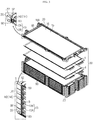
- FIG. 1 is an exploded perspective view of a battery module according to an embodiment of the present disclosure.
- a battery module 190 includes a battery stack 30, sealing members 70 and 90, cooling ducts 110, 130, 150, and 170, and a circuit unit 180.
- the battery stack 30 includes battery cartridges 20 and battery cells 4 and 8 of FIG. 2 .
- the battery cartridges 20 are sequentially stacked in the battery stack 30.
- Each of the battery cartridges 20 includes air induction holes 12 and 14.
- the air induction holes 12 and 14 are externally opened, as shown in FIGS. 2 and 3 , towards two side portions by being located at edges of the battery cartridge 20.
- the air induction holes 12 and 14 communicate with air paths (not shown) provided inside the battery cartridge 20, through opening holes H1 and H2.
- the battery cells 4 and 8 are located between the battery cartridges 20.
- the two battery cells 4 and 8 are mounted between the two adjacent battery cartridges 20 as shown in FIG. 2 , and the two battery cells 4 and 8 are in contact face-to-face between the battery cartridges 20.
- the sealing members 70 and 90 are located between the battery stack 30 and the cooling ducts 110, 130, 150, and 170.
- the sealing members 70 and 90 are distinguished into first sealing members 70 and second sealing members 90.
- the first sealing members 70 are located between the battery stack 30 and the first left and right cooling ducts 110 and 150 of the battery stack 30 in an arrangement order in a direction indicated by an arrow D.
- the second sealing members 90 are located between the battery stack 30 and the second left and right cooling ducts 130 and 170 of the battery stack 30 in the arrangement order in the direction indicated by the arrow D.
- the first and second sealing members 70 and 90 are configured to block direct inflow of air from outside of the cooling ducts 110, 130, 150, and 170 to spaces between the battery stack 30 and the cooling ducts 110, 130, 150, and 170.
- the first and second sealing members 70 and 90 are formed of one of glue, rubber, silicon, and poly urethane.
- the cooling ducts 110, 130, 150, and 170 may contact the battery cartridges 20 by being located at two side portions of the battery stack 30.
- the cooling ducts 110, 130, 150, and 170 are opened towards combining regions of the battery cartridges 20.
- the cooling ducts 110, 130, 150, and 170 respectively include air access holes 105, 125, 148, and 168 opened in a stacked direction of the battery cartridges 20 around the uppermost battery cartridge 20 from among the battery cartridges 20.
- the cooling ducts 110, 130, 150, and 170 are each thicker by a certain thickness T at a lower portion than an upper portion.
- the cooling ducts 110, 130, 150, and 170 are able to uniformly control a flow rate of air in an up-and-down direction according to a thickness difference between the lower portion and the upper portion, while sucking or discharging air through the air access holes 105, 125, 148, and 168.
- the cooling ducts 110, 130, 150, and 170 include pairs of connector boards P located along edges of regions opened towards the battery stack 30, and accommodation boards M protruding from the connector boards P and facing face-to-face with partial regions of side surfaces of the battery stack 30.
- some cooling ducts 150 and 170 from among the cooling ducts 110, 130, 150, and 170 include blast fans 144 and 164.
- the cooling ducts 110 and 130 suck air through the air access holes 105 and 125 from the outside, the air reaches the cooling ducts 150 and 170 from the cooling ducts 110 and 130 through the air induction holes 12 and 14 and air paths of the battery cartridges 20, and the cooling ducts 150 and 170 discharge the air from the inside to the outside through the air access holes 148 and 148.
- the circuit unit 180 is located at a front end of the battery stack 30 to be electrically connected to an electrode leads 2 of FIG. 2 of the battery cells 4 and 8.
- the circuit unit 180 is configured to sense a voltage of the battery cell 4 or 8 through the electrode leads 2 of the battery cells 4 and 8 in the battery cartridges 20, and output a sensing signal to the outside.
- FIG. 2 is an enlarged exploded perspective view of battery stack and a first sealing member of the battery module of FIG. 1 .
- the battery cartridges 20 accommodate the two battery cells 4 and 8 between the two battery cartridges 20, by using two battery cartridges 20 as one unit.
- the battery cartridges 20 have first grooves G1 on parts of side walls of the battery stack 30. In other words, the first grooves G1 are located on two facing side surfaces of the battery cartridge 20.
- the first groove G1 is recessed by a certain depth into the battery cartridge 20 from the side surface of the battery cartridge 20.
- the first groove G1 is vertically opened and has left and right internal walls IW1 parallel to the stacked direction of the battery cartridges 20.
- the first grooves G1 communicate with each other along the stacked direction of the battery cartridges 20, and accommodate the first sealing member 70 between the internal walls IW1 and the bottoms in the battery cartridges 20.
- the battery cartridges 20 include a lower cooling fin 15 and an upper cooling fin 16 parallel to each other and spaced apart from each other by a certain interval at a lower portion and an upper portion of an outer frame 18. An edge of the lower cooling fin 15 and an edge of the upper cooling fin 16 are fixed to the outer frame 18 via an insert injection process or the like.
- the lower cooling fin 15 and the upper cooling fin 16 define an air path (not shown) forming a horizontal flow path of air in the battery cartridge 20.
- the air path communicates with the air induction holes 12 each located on two side surfaces of the battery cartridge 20.
- the air induction holes 12 protrude towards a side portion of the battery cartridge 20 from the bottom of the first groove G1.
- the air induction hole 12 has an opening hole H1 having a slit shape on the outer frame 18 of the battery cartridge 20 so as to expose the air path between the lower cooling fin 15 and the upper cooling fin 16 to the outside of the battery cartridge 20.
- the opening hole H1 is defined by a wall 11 having a rectangular shape protruding from the bottom of the first groove G1.
- the wall 11 has an incline forming a certain angle with respect to the bottom of the first groove G1, and includes a pair of base walls 11A spaced apart from each other by a height of the opening hole H1, and a flange 11B located parallel to the internal wall IW1 of the first groove G1 and connecting two end portions of the pair of base walls 11A.
- the first sealing member 70 is located, in the battery cartridges 20, between the internal walls IW1 of the first grooves G1 and the flanges 11B of the opening holes H1, on a bottom surface of the first groove G1 below the base wall 11A of the lowest battery cartridge 20, and on a bottom surface of the first groove G1 on the base wall 11A of the uppermost battery cartridge 20.
- the first sealing member 70 is located on boundaries B of the first grooves G1 so as to be located between contacting regions of the base walls 11A in the battery cartridges 20.
- the first sealing member 70 includes an outer sealing frame 45, sealing ribs 55, and middle sealing frames 65.
- the outer sealing frame 45 is located between the internal walls IW1 of the first grooves G1 and the walls 11 of the opening holes H1, on the bottom surface of the first groove G1 along a length direction of the wall 11 below the base wall 11A of the lowermost battery cartridge 20, and on the bottom surface of the first groove G1 along the length direction of the wall 11 on the base wall 11A of the uppermost battery cartridge 20.
- the outer sealing frame 45 passes the boundaries B of the battery cartridges 20 by being located, roughly in a quadrangular shape on bottoms of the first grooves G1, on the side surfaces of the battery cartridges 20.
- the sealing ribs 55 each protrude towards the internal walls IW1 of the first grooves G1 and the flanges 11B of the walls 11 from the outer sealing frame 45 around contacting regions of the flanges 11B.
- the sealing ribs 55 are approximately parallel to the boundaries B of the first grooves G1 on the side surfaces of the battery cartridges 20. According to an embodiment, the sealing ribs 55 protrude perpendicularly from the outer sealing frame 45 around the boundaries B of the adjacent first grooves G1.
- the middle sealing frames 65 are located in the boundaries B of the first grooves G1 to contact the outer sealing frame 45 and the sealing ribs 55 at the contacting regions of the flanges 11B.
- the middle sealing frame 65 is located along the boundary B of the battery cartridges 20 on a boundary surface S of the battery cartridges 20.
- the middle sealing frame 65 is located between the adjacent air induction holes 12. According to another embodiment, the middle sealing frame 65 is located along the boundary B of the adjacent air induction holes 12 to contact the corresponding sealing rib 55.
- FIG. 3 is an enlarged exploded perspective view of the battery stack and a second sealing member of the battery module of FIG. 1 .
- the battery cartridges 20 include second grooves G2 spaced apart from the first grooves G1 of FIG. 2 .
- the battery cartridges 20 include the second grooves G2 on the side walls of the battery stack 30.
- the second grooves G2 are located on two facing side surfaces of the battery cartridges 20.
- the second groove G2 is recessed by a certain depth into the battery cartridge 20 from the side surface of the battery cartridge 20.
- the second groove G2 is vertically opened and includes left and right internal walls IW2 parallel to the stacked direction of the battery cartridges 20.
- the second grooves G2 communicate with each other in the stacked direction of the battery cartridges 20, and accommodate the second sealing member 90 between the internal walls IW2 and bottoms in the battery cartridges 20.
- the battery cartridges 20 include the lower cooling fins 15 and the upper cooling fins 16 parallel to each other and spaced part from each other by a certain interval at the lower portion and the upper portion of an outer frame 18.
- the lower cooling fin 15 and the upper cooling fin 16 define the air path (not shown) forming the horizontal flow path of air in the battery cartridge 20.
- the air path communicates with the air induction holes 14 each located on two side surfaces of the battery cartridge 20.
- the air induction holes 14 protrude towards a side portion of the battery cartridge 20 from the bottom of the second groove G2.
- the air induction hole 14 has an opening hole H2 having a slit shape on the outer frame 18 of the battery cartridge 20 so as to expose the air path between the lower cooling fin 15 and the upper cooling fin 16 to the outside of the battery cartridge 20.
- the opening hole H2 is defined by a wall 13 having a rectangular shape protruding from the bottom of the first groove G1.
- the wall 13 has an incline forming a certain angle with respect to the bottom of the second groove G2, and includes a pair of base walls 13A spaced apart from each other by a height of the opening hole H2, and a pair of flanges 13B located parallel to the internal walls IW2 of the second groove G2 and connecting two end portions of the pair of base walls 13A.
- the second sealing member 90 is located, in the battery cartridges 20, between the internal walls IW2 of the second grooves G2 and the flanges 13B of the opening holes H2, on a bottom surface of the second groove G2 below the base wall 13A of the lowest battery cartridge 20, and on a bottom surface of the second groove G2 on the base wall 13A of the uppermost battery cartridge 20. Also, the first sealing member 90 is located on boundaries B of the second grooves G2 so as to be located between contacting regions of the base walls 13A in the battery cartridges 20.
- the second sealing member 90 includes an outer sealing frame 83, sealing ribs 86, and middle sealing frames 89.
- the outer sealing frame 83 is located between the internal walls IW2 of the second grooves G2 and the walls 13 of the opening holes H2, on the bottom surface of the second groove G2 along a length direction of the wall 13 below the base wall 13A of the lowermost battery cartridge 20, and on the bottom surface of the second groove G2 along the length direction of the wall 13 on the base wall 13A of the uppermost battery cartridge 20.
- the outer sealing frame 45 passes the boundaries B of the battery cartridges 20 by being located, roughly in a quadrangular shape on bottoms of the second grooves G2, on the side surfaces of the battery cartridges 20.
- the sealing ribs 86 each protrude towards the internal walls IW2 of the second grooves G2 and the flanges 13B of the walls 13 from the outer sealing frame 83 around contacting regions of the flanges 13B.
- the sealing ribs 86 are approximately parallel to the boundaries B of the second grooves G2 on the side surfaces of the battery cartridges 20. According to an embodiment, the sealing ribs 86 protrude perpendicularly from the outer sealing frame 83 around the boundaries B of the adjacent second grooves G2.
- the middle sealing frames 89 are located in the boundaries B of the second grooves G2 to contact the outer sealing frame 83 and the sealing ribs 86 at the contacting regions of the flanges 13B.
- the middle sealing frame 89 is located along the boundary B of the battery cartridges 20 on the boundary surface S of the battery cartridges 20.
- the middle sealing frame 89 is located between the adjacent air induction holes 14. According to another embodiment, the middle sealing frame 89 is located along the boundary B of the adjacent air induction holes 14 to contact the corresponding sealing rib 86.
- first and second sealing members 70 and 90 have been described with respect to the left side wall of the battery stack 30, but the first and second sealing members 70 and 90 may also be provided on the right side wall of the battery stack 30.
- the left and right side walls of the battery stack 30 have the same structure.
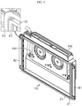
- FIG. 4 is an enlarged perspective view of a cooling duct of FIG. 1 .
- the cooling duct 150 is opened towards the battery cartridges 20 of FIG. 1 .
- the cooling duct 150 includes the blast fans 144 and the air access hole 148 above the blast fans 144.
- the blast fans 144 discharge air to the air access hole 148 of the cooling duct 150 by introducing the air that passed through the air access hole 105 of the cooling duct 110, and the air induction holes 12 and air paths of the battery cartridges 20 from the outside of the cooling duct 110 of FIG. 1 to the cooling duct 150.
- the cooling duct 150 may cover the first grooves G1 of the battery cartridges 20 by being located on the side surfaces of the battery cartridges 20.
- the cooling duct 150 includes a pair of connector boards P1 and P2 at an edge of the cooling duct 150.
- the connector boards P1 and P2 are matched to the outer sealing frame 45 of the first sealing member 70 of FIG. 2 , and protrude from the edge of the cooling duct 150. End portions of the connector boards PI and 2 roughly have a quadrangular shape.
- the cooling duct 150 includes a groove portion G3 between the connector boards PI and P2.
- the cooling duct 150 further includes accommodation boards M1 and M2 respectively located perpendicular to the connector boards P1 and P2 and extending from the connector boards P1 and p2 to the two side portions.
- each of the cooling ducts 110, 130, and 170 of FIG. 1 has the similar shape as the cooling duct 150.
- each of the cooling ducts 110, 130, and 170 includes the connector boards P1 and P2 and the accommodation boards M1 and M2.
- the cooling ducts 110 and 130 do not include a blast fan.
- FIG. 5 is a plan view of a combined shape of a battery stack, sealing members, and cooling ducts, which is taken along a line I-I' of FIG. 1 .
- the line I-I' passes between the battery cartridges of FIG. 1 .
- each of the cooling ducts 110 and 150 covers the first grooves G1 by contacting the first sealing member 70 through the connector boards PI and P2.
- Each of the cooling ducts 130 and 170 covers the second grooves G2 by contacting the second sealing member 90 through the connector boards PI and P2.
- cooling duct 110 contacts the outer sealing frame 45 of the first sealing member 70 through the connector boards P1 and P2 along the edges of the first grooves G1 in the battery cartridges 20.
- the cooling duct 110 is adhered to the side wall of the battery stack 30 of FIG. 2 while covering the first grooves G1 through a close contact of the connector boards P1 and P2 and the outer sealing frame 45.
- the groove portion G3 between the connector boards P1 and P2 is mostly filled by the outer sealing frame 45 of the first sealing member 70, and in detail, is also filled by the outer sealing frame 45 and the sealing ribs 55 around the boundary B of FIG. 2 of the battery cartridges 20.
- the cooling duct 110 is adhered on the side wall of the battery stack 20 at the left and right of the first grooves G1 through the accommodation boards M1 and M2.
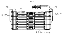
- FIG. 6 is a schematic view for describing an assembly method and operation mechanism of a battery stack based on a combined shape of a battery stack, sealing members, and cooling ducts in the direction indicated by the arrow D of FIG. 1 .
- the battery cartridges 20, the sealing members 70 and 90, and the cooling ducts 110, 130, 150, and 170 may be prepared as shown in FIG. 1 . Then, the battery cartridges 20 may be sequentially stacked on each other. At this time, the battery cells 4 and 8 may be inserted between the battery cartridges 20. The battery cells 4 and 8 and the battery cartridges 20 may form the battery stack 30.
- the sealing member 70 may be formed into the middle sealing frames 65 of FIGS. 2 and 3 between the battery cartridges 20, formed into the outer sealing frame 45 of FIG. 2 along the edges of the first grooves G1 of FIG. 2 in the battery cartridges 20, and formed into the sealing ribs 55 around the boundary B of FIG. 2 of the battery cartridges 20.
- the sealing member 90 may be formed into the middle sealing frames 89 of FIG. 3 between the battery cartridges 20, formed into the outer sealing frame 83 of FIG. 3 along the edges of the second grooves G2 of FIG. 3 in the battery cartridges 20, and formed into the sealing ribs 86 around the boundary B of FIG. 3 of the battery cartridges 20.
- the cooling ducts 110, 130, 150, and 170 may be adhered to the two side walls of the battery stack 30.
- the connector boards P1 and P2 of FIG. 4 of the cooling ducts 110, 130, 150, and 170 may closely contact the outer sealing frames 45 and 83 and the sealing ribs 55 and 86 of the sealing members 70 and 90.
- the accommodation boards M1 and M2 of FIG. 4 of the cooling ducts 110, 130, 150, and 170 may be fixed to the battery stack 30 by using a screw member SM of FIG. 5 .
- long bolts (not shown) may be fastened to the battery stack 30.
- the long bolts may tightly fix the battery cartridges 20 in a vertical direction by being inserted into long bolt fastening holes 18A of FIG. 2 or 3 of the outer frames 18 of FIG. 2 or 3 .
- the cooling ducts 110 and 130 may suck external air through the air access holes 105 and 125.
- the sealing members 70 and 90 seal the grooves G1 and G2 located on two side walls of the battery stack 30, together with the cooling ducts 110, 130, 150, and 170, the air may flow along flow lines F0, F1, F2, and F3 in the battery cartridges 20 and the cooling ducts 110, 130, 150, and 170.
- the flow line F0 displays flow of air introduced to the cooling ducts 110 and 130. Also, the flow lines F1 and F2 display flow of air inside each of the battery cartridges 20, and the flow line F3 display flow of air discharged from the cooling ducts 150 and 170.
- the air may uniformly and quickly cool the battery cells 4 and 8 provided between the battery cartridges 20 through the cooling ducts 110, 130, 150, and 170, and the air paths located inside the battery cartridges 20 such that the cooling ducts 110, 130, 150, and 170 communicate with each other.
Landscapes
- Chemical & Material Sciences (AREA)
- Chemical Kinetics & Catalysis (AREA)
- Electrochemistry (AREA)
- General Chemical & Material Sciences (AREA)
- Engineering & Computer Science (AREA)
- Manufacturing & Machinery (AREA)
- Secondary Cells (AREA)
- Battery Mounting, Suspending (AREA)
Abstract
Description
- The present disclosure relates to a battery module suitable for increasing cooling efficiency of cooled structures through a cooling structure by bringing the cooling structure into close contact with the cooled structures.
- The present application claims priority to Korean Patent Application No.
10-2015-0085237 filed on June 16, 2015 - Recently, in order to reduce air pollution caused by exhaust gases of vehicles, the vehicles are being manufactured based on studies for securing driving power by using an internal combustion engine and/or an electric motor. In this regard, the vehicles have been evolved in an order of a hybrid vehicle, a plug-in hybrid vehicle, and an electric vehicle. In this case, the hybrid vehicle and the plug-in hybrid vehicle include an internal combustion engine, an electric motor, and a battery pack, and the electric vehicle includes an electric motor and a battery pack without an internal combustion engine.
- In addition, the battery pack has been evolved together with the hybrid vehicle, the plug-in hybrid vehicle, and the electric vehicle. The battery pack is configured to be chargeable outside and/or inside of the electric vehicle. The battery pack includes a cooling structure and a battery module, and the cooling structure surrounds the battery module. The battery module includes battery accommodation structures (for example, cartridges) that are sequentially stacked on each other, and battery cells between the battery accommodation structures. The battery cells externally generate heat via repeated charging and discharging. At this time, the cooling structure cools the battery cells via a heat exchange, by exchanging heat with the battery cells by using external air while the battery module is driven.
- Accordingly, a shape of the cooling structure largely affects cooling effects of the battery cells per unit time. A lot of studies related to the shape of the cooling structure are being conducted. An example of the studies is
KR 10-2014-0141825 (published on December 11, 2014 - The cover members are located below and above the elastic pads to surround the elastic pads in a sandwich structure. The frame members have a shape of '[', and accommodates the elastic pads, the battery cells, and the cover members by being located along edges of the battery cells and cover members. Here, the elastic pads and the cover members fix the battery cells inside the frame members, and the cover members cools the battery cells via a heat exchange, by exchanging heat with external air.
- However, since the battery cells are surrounded by the elastic members, the cover members, and the frame members, heat of the battery cells are gradually accumulated between the elastic members, the cover members, and the frame members while the battery module is driven. The accumulated heat of the battery cells not only degrades electric characteristics of the battery cells, but also changes shapes of the elastic members, the cover members, and the frame members.
- The present disclosure is designed based on the background art described above, and is directed to providing a battery module suitable for adequately cooling battery cells through battery cartridges by including the battery cells between the battery cartridges that are sequentially stacked on each other.
- In one aspect of the present disclosure, there is provided a battery module including: a battery stack including: battery cartridges having grooves recessed from side surfaces of the battery cartridges to be opened vertically at the side surfaces, air induction holes protruding from bottoms of the grooves, and air paths communicating with opening holes of the air induction holes; and at least one battery cell alternately stacked with the battery cartridges; a sealing member including an outer sealing frame located along edges of the grooves of the battery stack, sealing ribs perpendicularly protruding from the outer sealing frame around boundaries of adjacent grooves, and middle sealing frames located between adjacent air induction holes; and a cooling duct including an air access hole covering the grooves and communicating with the air induction holes, and including a groove portion located along the outer sealing frame to accommodate the outer sealing frame.
- According to the present disclosure, the grooves may be located at two facing side surfaces of the battery cartridges.
- Preferably, the two grooves may be located each of two facing side surfaces of the battery cartridges.
- According to the present disclosure, the air induction holes may include rectangular walls defining the opening holes.
- Preferably, the rectangular walls may include pairs of base walls having inclines forming certain angles with the bottoms of the grooves and spaced apart from each other by heights of the opening holes, and pairs of flanges connecting two end portions of the pairs of base walls.
- According to the present disclosure, the battery cartridges may include the air paths between lower cooling fins and upper cooling fins spaced apart from each other at certain intervals, and edges of the lower cooling fins and edges of the upper cooling fins may be fixed to borders of the battery cartridges.
- According to the present disclosure, the outer sealing frame may be located, roughly in a quadrangular shape at the bottoms of the grooves, on the side surfaces of the battery cartridges, and pass boundaries of the battery cartridges.
- According to the present disclosure, the sealing ribs may be located roughly parallel to the boundaries of the grooves, on the side surfaces of the battery cartridges.
- According to the present disclosure, the middle sealing frames may be located along boundaries of the adjacent air induction holes to contact the corresponding sealing ribs.
- According to the present disclosure, the cooling duct may include a pair of connector boards defining the groove portion.
- Preferably, the cooling duct may be adhered to the battery cartridges through the pair of connector boards to cover the grooves.
- According to the present disclosure, the pair of connector boards may protrude from the cooling duct towards the grooves.
- Preferably, the cooling duct may further include accommodation boards respectively located perpendicular to the pair of connector boards and extending from the pair of connector boards to two side portions, and the accommodation boards may be fixed to side walls of the battery stack around the grooves.
- According to the present disclosure, a thickness of the cooling duct may gradually decrease from an uppermost battery cartridge to a lowermost battery cartridge when viewed from a stack direction of the battery cartridges.
- A battery module according to the present disclosure includes battery cartridges that are sequentially stacked on each other, battery cells between the battery cartridges, and cooling ducts located at two side portions of the battery cartridges, and since the battery module has an air path penetrating one side surface and another side surface of the battery cartridge, the battery module may effectively cool the battery cells through air flowing along the cooling ducts and the battery cartridges by communicating the cooling ducts and the battery cartridges.
- A battery module according to the present disclosure has a groove at a side surface of a battery cartridge facing a cooling duct, and includes a sealing member passing boundaries of battery cartridges at the groove and located between the battery cartridges, and accordingly, the battery module may maintain close contact of the battery cartridges and the cooling duct by bringing the cooling duct into contact with the sealing member.
- Since a battery module according to the present disclosure includes a sealing member along a stacked direction of battery cartridges, the battery module may cool battery cells inserted between the battery cartridges to an adequate temperature within a short period of time by concentrating air flowing along cooling ducts and the battery cartridges while the battery module is driven to air paths of the battery cartridges.
- Since a battery module according to the present disclosure includes a sealing member passing boundaries of battery cartridges between the battery cartridges and cooling duct, the battery module blocks external air directly flowing in through an edge of the cooling duct without passing through an air access hole of the cooling duct such that a cooling degree of battery cells per unit time is estimated.
- A battery module according to the present disclosure includes a groove at a side surface of each of battery cartridges, and adheres a cooling duct to the battery cartridges by a depth of the groove such that a shape of the battery module is entirely compact, and accordingly, an installation space of the battery module may be efficiently increased.
- The accompanying drawings illustrate a preferred embodiment of the present disclosure and together with the foregoing disclosure, serve to provide further understanding of the technical features of the present disclosure, and thus, the present disclosure is not construed as being limited to the drawing.
-
FIG. 1 is an exploded perspective view of a battery module according to an embodiment of the present disclosure. -
FIG. 2 is an enlarged exploded perspective view of battery stack and a first sealing member of the battery module ofFIG. 1 . -
FIG. 3 is an enlarged exploded perspective view of the battery stack and a second sealing member of the battery module ofFIG. 1 . -
FIG. 4 is an enlarged perspective view of a cooling duct ofFIG. 1 . -
FIG. 5 is a plan view of a combined shape of a battery stack, sealing members, and cooling ducts, which is taken along a line I-I' ofFIG. 1 . -
FIG. 6 is a schematic view for describing an assembly method and operation mechanism of a battery stack based on a combined shape of a battery stack, sealing members, and cooling ducts in a direction indicated by an arrow D ofFIG. 1 . - Hereinafter, preferred embodiments of the present disclosure will be described in detail with reference to the accompanying drawings. Prior to the description, it should be understood that the terms used in the specification and the appended claims should not be construed as limited to general and dictionary meanings, but interpreted based on the meanings and concepts corresponding to technical aspects of the present disclosure on the basis of the principle that the inventor is allowed to define terms appropriately for the best explanation. Therefore, the description proposed herein is just a preferable example for the purpose of illustrations only, not intended to limit the scope of the disclosure, so it should be understood that other equivalents and modifications could be made thereto without departing from the scope of the disclosure.
- In one or more embodiments described below, a battery cell denotes a lithium secondary battery. Here, the lithium secondary battery refers to a secondary battery in which lithium ions act as working ions during charging and discharging to induce an electrochemical reaction in a positive electrode and a negative electrode. However, it is obvious that the present disclosure is not limited by a type of battery.
-
FIG. 1 is an exploded perspective view of a battery module according to an embodiment of the present disclosure. - Referring to
FIG. 1 , abattery module 190 according to the present disclosure includes abattery stack 30, sealingmembers cooling ducts circuit unit 180. Thebattery stack 30 includesbattery cartridges 20 andbattery cells FIG. 2 . Thebattery cartridges 20 are sequentially stacked in thebattery stack 30. Each of thebattery cartridges 20 includes air induction holes 12 and 14. - Preferably, the air induction holes 12 and 14 are externally opened, as shown in
FIGS. 2 and3 , towards two side portions by being located at edges of thebattery cartridge 20. According to an embodiment, the air induction holes 12 and 14 communicate with air paths (not shown) provided inside thebattery cartridge 20, through opening holes H1 and H2. Thebattery cells battery cartridges 20. - For example, the two
battery cells adjacent battery cartridges 20 as shown inFIG. 2 , and the twobattery cells battery cartridges 20. The sealingmembers battery stack 30 and the coolingducts members first sealing members 70 and second sealingmembers 90. - The
first sealing members 70 are located between thebattery stack 30 and the first left andright cooling ducts battery stack 30 in an arrangement order in a direction indicated by an arrow D. Thesecond sealing members 90 are located between thebattery stack 30 and the second left andright cooling ducts battery stack 30 in the arrangement order in the direction indicated by the arrow D. - According to an embodiment, excluding a case in which the
cooling ducts second sealing members ducts battery stack 30 and the coolingducts - Preferably, the first and
second sealing members ducts battery cartridges 20 by being located at two side portions of thebattery stack 30. Preferably, the coolingducts battery cartridges 20. - According to an embodiment, the cooling
ducts battery cartridges 20 around theuppermost battery cartridge 20 from among thebattery cartridges 20. Here, the coolingducts - Accordingly, the cooling
ducts ducts battery stack 30, and accommodation boards M protruding from the connector boards P and facing face-to-face with partial regions of side surfaces of thebattery stack 30. - According to another embodiment, some cooling
ducts ducts blast fans blast fans ducts ducts ducts battery cartridges 20, and the coolingducts - The
circuit unit 180 is located at a front end of thebattery stack 30 to be electrically connected to an electrode leads 2 ofFIG. 2 of thebattery cells circuit unit 180 is configured to sense a voltage of thebattery cell battery cells battery cartridges 20, and output a sensing signal to the outside. -
FIG. 2 is an enlarged exploded perspective view of battery stack and a first sealing member of the battery module ofFIG. 1 . - Referring to
FIG. 2 , in thebattery stack 30, thebattery cartridges 20 accommodate the twobattery cells battery cartridges 20, by using twobattery cartridges 20 as one unit. Thebattery cartridges 20 have first grooves G1 on parts of side walls of thebattery stack 30. In other words, the first grooves G1 are located on two facing side surfaces of thebattery cartridge 20. - Preferably, the first groove G1 is recessed by a certain depth into the
battery cartridge 20 from the side surface of thebattery cartridge 20. According to an embodiment, the first groove G1 is vertically opened and has left and right internal walls IW1 parallel to the stacked direction of thebattery cartridges 20. - Here, the first grooves G1 communicate with each other along the stacked direction of the
battery cartridges 20, and accommodate the first sealingmember 70 between the internal walls IW1 and the bottoms in thebattery cartridges 20. Also, thebattery cartridges 20 include alower cooling fin 15 and anupper cooling fin 16 parallel to each other and spaced apart from each other by a certain interval at a lower portion and an upper portion of anouter frame 18. An edge of thelower cooling fin 15 and an edge of theupper cooling fin 16 are fixed to theouter frame 18 via an insert injection process or the like. - The
lower cooling fin 15 and theupper cooling fin 16 define an air path (not shown) forming a horizontal flow path of air in thebattery cartridge 20. The air path communicates with the air induction holes 12 each located on two side surfaces of thebattery cartridge 20. Preferably, the air induction holes 12 protrude towards a side portion of thebattery cartridge 20 from the bottom of the first groove G1. - According to an embodiment, the
air induction hole 12 has an opening hole H1 having a slit shape on theouter frame 18 of thebattery cartridge 20 so as to expose the air path between thelower cooling fin 15 and theupper cooling fin 16 to the outside of thebattery cartridge 20. The opening hole H1 is defined by awall 11 having a rectangular shape protruding from the bottom of the first groove G1. - The
wall 11 has an incline forming a certain angle with respect to the bottom of the first groove G1, and includes a pair ofbase walls 11A spaced apart from each other by a height of the opening hole H1, and aflange 11B located parallel to the internal wall IW1 of the first groove G1 and connecting two end portions of the pair ofbase walls 11A. - Meanwhile, the first sealing
member 70 is located, in thebattery cartridges 20, between the internal walls IW1 of the first grooves G1 and theflanges 11B of the opening holes H1, on a bottom surface of the first groove G1 below thebase wall 11A of thelowest battery cartridge 20, and on a bottom surface of the first groove G1 on thebase wall 11A of theuppermost battery cartridge 20. - Also, the first sealing
member 70 is located on boundaries B of the first grooves G1 so as to be located between contacting regions of thebase walls 11A in thebattery cartridges 20. In detail, the first sealingmember 70 includes anouter sealing frame 45, sealingribs 55, and middle sealing frames 65. - The
outer sealing frame 45 is located between the internal walls IW1 of the first grooves G1 and thewalls 11 of the opening holes H1, on the bottom surface of the first groove G1 along a length direction of thewall 11 below thebase wall 11A of thelowermost battery cartridge 20, and on the bottom surface of the first groove G1 along the length direction of thewall 11 on thebase wall 11A of theuppermost battery cartridge 20. - Preferably, the
outer sealing frame 45 passes the boundaries B of thebattery cartridges 20 by being located, roughly in a quadrangular shape on bottoms of the first grooves G1, on the side surfaces of thebattery cartridges 20. The sealingribs 55 each protrude towards the internal walls IW1 of the first grooves G1 and theflanges 11B of thewalls 11 from theouter sealing frame 45 around contacting regions of theflanges 11B. - Preferably, the sealing
ribs 55 are approximately parallel to the boundaries B of the first grooves G1 on the side surfaces of thebattery cartridges 20. According to an embodiment, the sealingribs 55 protrude perpendicularly from theouter sealing frame 45 around the boundaries B of the adjacent first grooves G1. - The middle sealing frames 65 are located in the boundaries B of the first grooves G1 to contact the
outer sealing frame 45 and the sealingribs 55 at the contacting regions of theflanges 11B. Preferably, themiddle sealing frame 65 is located along the boundary B of thebattery cartridges 20 on a boundary surface S of thebattery cartridges 20. - According to an embodiment, the
middle sealing frame 65 is located between the adjacent air induction holes 12. According to another embodiment, themiddle sealing frame 65 is located along the boundary B of the adjacent air induction holes 12 to contact the corresponding sealingrib 55. -
FIG. 3 is an enlarged exploded perspective view of the battery stack and a second sealing member of the battery module ofFIG. 1 . - Referring to
FIG. 3 , in thebattery stack 30, thebattery cartridges 20 include second grooves G2 spaced apart from the first grooves G1 ofFIG. 2 . Here, thebattery cartridges 20 include the second grooves G2 on the side walls of thebattery stack 30. In other words, the second grooves G2 are located on two facing side surfaces of thebattery cartridges 20. - Preferably, the second groove G2 is recessed by a certain depth into the
battery cartridge 20 from the side surface of thebattery cartridge 20. According to an embodiment, the second groove G2 is vertically opened and includes left and right internal walls IW2 parallel to the stacked direction of thebattery cartridges 20. - Here, the second grooves G2 communicate with each other in the stacked direction of the
battery cartridges 20, and accommodate the second sealingmember 90 between the internal walls IW2 and bottoms in thebattery cartridges 20. Also, thebattery cartridges 20 include thelower cooling fins 15 and theupper cooling fins 16 parallel to each other and spaced part from each other by a certain interval at the lower portion and the upper portion of anouter frame 18. - The
lower cooling fin 15 and theupper cooling fin 16 define the air path (not shown) forming the horizontal flow path of air in thebattery cartridge 20. The air path communicates with the air induction holes 14 each located on two side surfaces of thebattery cartridge 20. Preferably, the air induction holes 14 protrude towards a side portion of thebattery cartridge 20 from the bottom of the second groove G2. - According to an embodiment, the
air induction hole 14 has an opening hole H2 having a slit shape on theouter frame 18 of thebattery cartridge 20 so as to expose the air path between thelower cooling fin 15 and theupper cooling fin 16 to the outside of thebattery cartridge 20. The opening hole H2 is defined by awall 13 having a rectangular shape protruding from the bottom of the first groove G1. - The
wall 13 has an incline forming a certain angle with respect to the bottom of the second groove G2, and includes a pair ofbase walls 13A spaced apart from each other by a height of the opening hole H2, and a pair offlanges 13B located parallel to the internal walls IW2 of the second groove G2 and connecting two end portions of the pair ofbase walls 13A. - Meanwhile, the second sealing
member 90 is located, in thebattery cartridges 20, between the internal walls IW2 of the second grooves G2 and theflanges 13B of the opening holes H2, on a bottom surface of the second groove G2 below thebase wall 13A of thelowest battery cartridge 20, and on a bottom surface of the second groove G2 on thebase wall 13A of theuppermost battery cartridge 20. Also, the first sealingmember 90 is located on boundaries B of the second grooves G2 so as to be located between contacting regions of thebase walls 13A in thebattery cartridges 20. - In detail, the second sealing
member 90 includes anouter sealing frame 83, sealingribs 86, and middle sealing frames 89. Theouter sealing frame 83 is located between the internal walls IW2 of the second grooves G2 and thewalls 13 of the opening holes H2, on the bottom surface of the second groove G2 along a length direction of thewall 13 below thebase wall 13A of thelowermost battery cartridge 20, and on the bottom surface of the second groove G2 along the length direction of thewall 13 on thebase wall 13A of theuppermost battery cartridge 20. - Preferably, the
outer sealing frame 45 passes the boundaries B of thebattery cartridges 20 by being located, roughly in a quadrangular shape on bottoms of the second grooves G2, on the side surfaces of thebattery cartridges 20. The sealingribs 86 each protrude towards the internal walls IW2 of the second grooves G2 and theflanges 13B of thewalls 13 from theouter sealing frame 83 around contacting regions of theflanges 13B. - Preferably, the sealing
ribs 86 are approximately parallel to the boundaries B of the second grooves G2 on the side surfaces of thebattery cartridges 20. According to an embodiment, the sealingribs 86 protrude perpendicularly from theouter sealing frame 83 around the boundaries B of the adjacent second grooves G2. - The middle sealing frames 89 are located in the boundaries B of the second grooves G2 to contact the
outer sealing frame 83 and the sealingribs 86 at the contacting regions of theflanges 13B. Preferably, themiddle sealing frame 89 is located along the boundary B of thebattery cartridges 20 on the boundary surface S of thebattery cartridges 20. - According to an embodiment, the
middle sealing frame 89 is located between the adjacent air induction holes 14. According to another embodiment, themiddle sealing frame 89 is located along the boundary B of the adjacent air induction holes 14 to contact the corresponding sealingrib 86. - In
FIGS. 2 and3 , the first andsecond sealing members battery stack 30, but the first andsecond sealing members battery stack 30. Here, the left and right side walls of thebattery stack 30 have the same structure. -
FIG. 4 is an enlarged perspective view of a cooling duct ofFIG. 1 . - Referring to
FIG. 4 , the coolingduct 150 is opened towards thebattery cartridges 20 ofFIG. 1 . Also, the coolingduct 150 includes theblast fans 144 and theair access hole 148 above theblast fans 144. Theblast fans 144 discharge air to theair access hole 148 of the coolingduct 150 by introducing the air that passed through theair access hole 105 of the coolingduct 110, and the air induction holes 12 and air paths of thebattery cartridges 20 from the outside of the coolingduct 110 ofFIG. 1 to the coolingduct 150. - According to an embodiment, the cooling
duct 150 may cover the first grooves G1 of thebattery cartridges 20 by being located on the side surfaces of thebattery cartridges 20. According to another embodiment, the coolingduct 150 includes a pair of connector boards P1 and P2 at an edge of the coolingduct 150. The connector boards P1 and P2 are matched to theouter sealing frame 45 of the first sealingmember 70 ofFIG. 2 , and protrude from the edge of the coolingduct 150. End portions of the connector boards PI and 2 roughly have a quadrangular shape. - Here, the cooling
duct 150 includes a groove portion G3 between the connector boards PI and P2. According to another embodiment, the coolingduct 150 further includes accommodation boards M1 and M2 respectively located perpendicular to the connector boards P1 and P2 and extending from the connector boards P1 and p2 to the two side portions. Meanwhile, each of the coolingducts FIG. 1 has the similar shape as the coolingduct 150. In other words, each of the coolingducts ducts -
FIG. 5 is a plan view of a combined shape of a battery stack, sealing members, and cooling ducts, which is taken along a line I-I' ofFIG. 1 . Here, the line I-I' passes between the battery cartridges ofFIG. 1 . - Referring to
FIG. 5 , each of the coolingducts member 70 through the connector boards PI and P2. Each of the coolingducts member 90 through the connector boards PI and P2. - Here, since the combined shapes of the cooling
ducts battery cartridges 20 are similar to one another, only onecooling duct 110 from among the coolingducts duct 110 contacts theouter sealing frame 45 of the first sealingmember 70 through the connector boards P1 and P2 along the edges of the first grooves G1 in thebattery cartridges 20. - In detail, the cooling
duct 110 is adhered to the side wall of thebattery stack 30 ofFIG. 2 while covering the first grooves G1 through a close contact of the connector boards P1 and P2 and theouter sealing frame 45. Here, the groove portion G3 between the connector boards P1 and P2 is mostly filled by theouter sealing frame 45 of the first sealingmember 70, and in detail, is also filled by theouter sealing frame 45 and the sealingribs 55 around the boundary B ofFIG. 2 of thebattery cartridges 20. - Preferably, the cooling
duct 110 is adhered on the side wall of thebattery stack 20 at the left and right of the first grooves G1 through the accommodation boards M1 and M2. -
FIG. 6 is a schematic view for describing an assembly method and operation mechanism of a battery stack based on a combined shape of a battery stack, sealing members, and cooling ducts in the direction indicated by the arrow D ofFIG. 1 . - Referring to
FIG. 6 , thebattery cartridges 20, the sealingmembers ducts FIG. 1 . Then, thebattery cartridges 20 may be sequentially stacked on each other. At this time, thebattery cells battery cartridges 20. Thebattery cells battery cartridges 20 may form thebattery stack 30. - While and after forming the
battery stack 30, the sealingmember 70 may be formed into the middle sealing frames 65 ofFIGS. 2 and3 between thebattery cartridges 20, formed into theouter sealing frame 45 ofFIG. 2 along the edges of the first grooves G1 ofFIG. 2 in thebattery cartridges 20, and formed into the sealingribs 55 around the boundary B ofFIG. 2 of thebattery cartridges 20. - Also, the sealing
member 90 may be formed into the middle sealing frames 89 ofFIG. 3 between thebattery cartridges 20, formed into theouter sealing frame 83 ofFIG. 3 along the edges of the second grooves G2 ofFIG. 3 in thebattery cartridges 20, and formed into the sealingribs 86 around the boundary B ofFIG. 3 of thebattery cartridges 20. Next, the coolingducts battery stack 30. - Here, the connector boards P1 and P2 of
FIG. 4 of the coolingducts ribs members FIG. 4 of the coolingducts battery stack 30 by using a screw member SM ofFIG. 5 . - Then, long bolts (not shown) may be fastened to the
battery stack 30. The long bolts may tightly fix thebattery cartridges 20 in a vertical direction by being inserted into longbolt fastening holes 18A ofFIG. 2 or3 of theouter frames 18 ofFIG. 2 or3 . - According to the present disclosure, when the
blast fans ducts ducts members battery stack 30, together with the coolingducts battery cartridges 20 and the coolingducts - Here, the flow line F0 displays flow of air introduced to the cooling
ducts battery cartridges 20, and the flow line F3 display flow of air discharged from the coolingducts - Accordingly, the air may uniformly and quickly cool the
battery cells battery cartridges 20 through the coolingducts battery cartridges 20 such that the coolingducts - The scope of the present disclosure is indicated by the claims which will be described in the following rather than the detailed description of the disclosure, and it should be understood that the claims and all modifications or modified forms drawn from the concept of the claims are included in the scope of the present disclosure.
Claims (14)
- A battery module comprising:a battery stack comprising: battery cartridges having grooves recessed from side surfaces of the battery cartridges to be opened vertically at the side surfaces, air induction holes protruding from bottoms of the grooves, and air paths communicating with opening holes of the air induction holes; and at least one battery cell alternately stacked with the battery cartridges;a sealing member comprising an outer sealing frame located along edges of the grooves of the battery stack, sealing ribs perpendicularly protruding from the outer sealing frame around boundaries of adjacent grooves, and middle sealing frames located between adjacent air induction holes; anda cooling duct comprising an air access hole covering the grooves and communicating with the air induction holes, and comprising a groove portion located along the outer sealing frame to accommodate the outer sealing frame.
- The battery module of claim 1, wherein the grooves are located at two facing side surfaces of the battery cartridges.
- The battery module of claim 1, wherein the two grooves are located each of two facing side surfaces of the battery cartridges.
- The battery module of claim 1, wherein the air induction holes comprise rectangular walls defining the opening holes.
- The battery module of claim 4, wherein the rectangular walls comprise pairs of base walls having inclines forming certain angles with the bottoms of the grooves and spaced apart from each other by heights of the opening holes, and pairs of flanges connecting two end portions of the pairs of base walls.
- The battery module of claim 1, wherein the battery cartridges comprise the air paths between lower cooling fins and upper cooling fins spaced apart from each other at certain intervals, and
edges of the lower cooling fins and edges of the upper cooling fins are fixed to borders of the battery cartridges. - The battery module of claim 1, wherein the outer sealing frame is located, roughly in a quadrangular shape at the bottoms of the grooves, on the side surfaces of the battery cartridges, and passes boundaries of the battery cartridges.
- The battery module of claim 1, wherein the sealing ribs are located roughly parallel to the boundaries of the grooves, on the side surfaces of the battery cartridges.
- The battery module of claim 1, wherein the middle sealing frames are located along boundaries of the adjacent air induction holes to contact the corresponding sealing ribs.
- The battery module of claim 1, wherein the cooling duct comprises a pair of connector boards defining the groove portion.
- The battery module of claim 10, wherein the cooling duct is adhered to the battery cartridges through the pair of connector boards to cover the grooves.
- The battery module of claim 10, wherein the pair of connector boards protrude from the cooling duct towards the grooves.
- The battery module of claim 10, wherein the cooling duct further comprises accommodation boards respectively located perpendicular to the pair of connector boards and extending from the pair of connector boards to two side portions, and
the accommodation boards are fixed to side walls of the battery stack around the grooves. - The battery module of claim 1, wherein a thickness of the cooling duct gradually decreases from an uppermost battery cartridge to a lowermost battery cartridge when viewed from a stack direction of the battery cartridges.
Priority Applications (1)
| Application Number | Priority Date | Filing Date | Title |
|---|---|---|---|
| PL16811904T PL3312932T3 (en) | 2015-06-16 | 2016-06-14 | Battery module |
Applications Claiming Priority (2)
| Application Number | Priority Date | Filing Date | Title |
|---|---|---|---|
| KR1020150085237A KR101928369B1 (en) | 2015-06-16 | 2015-06-16 | Battery Module |
| PCT/KR2016/006311 WO2016204491A1 (en) | 2015-06-16 | 2016-06-14 | Battery module |
Publications (3)
| Publication Number | Publication Date |
|---|---|
| EP3312932A4 EP3312932A4 (en) | 2018-04-25 |
| EP3312932A1 true EP3312932A1 (en) | 2018-04-25 |
| EP3312932B1 EP3312932B1 (en) | 2019-06-12 |
Family
ID=57545768
Family Applications (1)
| Application Number | Title | Priority Date | Filing Date |
|---|---|---|---|
| EP16811904.8A Active EP3312932B1 (en) | 2015-06-16 | 2016-06-14 | Battery module |
Country Status (7)
| Country | Link |
|---|---|
| US (1) | US10608296B2 (en) |
| EP (1) | EP3312932B1 (en) |
| JP (1) | JP6486504B2 (en) |
| KR (1) | KR101928369B1 (en) |
| CN (1) | CN107710494B (en) |
| PL (1) | PL3312932T3 (en) |
| WO (1) | WO2016204491A1 (en) |
Cited By (1)
| Publication number | Priority date | Publication date | Assignee | Title |
|---|---|---|---|---|
| RU2833941C1 (en) * | 2022-12-02 | 2025-01-31 | Энертек Интернэшнл, Инк. | Battery cell assembly for secondary lithium battery with heat dissipation function |
Families Citing this family (2)
| Publication number | Priority date | Publication date | Assignee | Title |
|---|---|---|---|---|
| KR102311075B1 (en) * | 2018-04-09 | 2021-10-07 | 주식회사 엘지에너지솔루션 | Battery Pack Having Pack Housing |
| CN116885366A (en) * | 2023-05-11 | 2023-10-13 | 刘昭 | A battery pack unit and its application |
Family Cites Families (18)
| Publication number | Priority date | Publication date | Assignee | Title |
|---|---|---|---|---|
| JP4242665B2 (en) * | 2002-05-13 | 2009-03-25 | パナソニック株式会社 | Battery pack cooling device and secondary battery |
| JP3624903B2 (en) * | 2002-07-04 | 2005-03-02 | 日産自動車株式会社 | Module battery |
| KR100891079B1 (en) * | 2005-02-07 | 2009-03-30 | 주식회사 엘지화학 | Battery Cartridge Connection System for Battery Module |
| WO2006093010A1 (en) * | 2005-03-01 | 2006-09-08 | Nec Corporation | Casing for module and casing for battery pack |
| WO2006135008A1 (en) * | 2005-06-17 | 2006-12-21 | Nec Lamilion Energy, Ltd. | Electric device assembly and electric device with film outer covering |
| KR101212369B1 (en) * | 2006-01-05 | 2012-12-13 | 에스케이이노베이션 주식회사 | Cooling structure of lithium ion secondary battery system |
| US7875378B2 (en) | 2006-03-06 | 2011-01-25 | Lg Chem, Ltd. | Voltage sensing member and battery module employed with the same |
| KR100896131B1 (en) | 2006-05-22 | 2009-05-08 | 주식회사 엘지화학 | Medium and large battery module |
| DE102008057210B4 (en) | 2008-11-13 | 2023-05-04 | Vitesco Technologies GmbH | cell holder, energy storage cell, cell holder stack and multi-cell energy storage |
| JP5244931B2 (en) * | 2011-02-22 | 2013-07-24 | 日立ビークルエナジー株式会社 | Power storage module |
| US9634302B2 (en) | 2011-11-18 | 2017-04-25 | Hitachi Automotive Systems, Ltd. | Secondary battery module |
| KR101987778B1 (en) * | 2012-05-11 | 2019-06-11 | 에스케이이노베이션 주식회사 | Secondary battery module having through type cool channel |
| CN104364931B (en) * | 2012-05-31 | 2016-06-29 | 本田技研工业株式会社 | Power storage module and fixing structure of power storage module |
| US20140227567A1 (en) * | 2013-02-14 | 2014-08-14 | Samsung Sdi Co., Ltd. | Battery module |
| KR101826861B1 (en) | 2013-05-31 | 2018-02-08 | 주식회사 엘지화학 | Secondary Battery and Battery Module Having the Same |
| KR101588251B1 (en) * | 2013-06-11 | 2016-01-25 | 주식회사 엘지화학 | Battery Module Having Structure for Prevention of Coolant and Venting Gas Mixing |
| KR101615941B1 (en) | 2013-08-29 | 2016-04-27 | 주식회사 엘지화학 | Battery Module Having Structure for Prevention of Coolant and Venting Gas Mixing |
| JP5988954B2 (en) | 2013-11-25 | 2016-09-07 | 大塚ポリテック株式会社 | Seal structure for packing and battery module |
-
2015
- 2015-06-16 KR KR1020150085237A patent/KR101928369B1/en active Active
-
2016
- 2016-06-14 PL PL16811904T patent/PL3312932T3/en unknown
- 2016-06-14 WO PCT/KR2016/006311 patent/WO2016204491A1/en not_active Ceased
- 2016-06-14 EP EP16811904.8A patent/EP3312932B1/en active Active
- 2016-06-14 JP JP2017560521A patent/JP6486504B2/en active Active
- 2016-06-14 US US15/574,314 patent/US10608296B2/en active Active
- 2016-06-14 CN CN201680033001.3A patent/CN107710494B/en active Active
Cited By (1)
| Publication number | Priority date | Publication date | Assignee | Title |
|---|---|---|---|---|
| RU2833941C1 (en) * | 2022-12-02 | 2025-01-31 | Энертек Интернэшнл, Инк. | Battery cell assembly for secondary lithium battery with heat dissipation function |
Also Published As
| Publication number | Publication date |
|---|---|
| US10608296B2 (en) | 2020-03-31 |
| EP3312932A4 (en) | 2018-04-25 |
| CN107710494B (en) | 2020-09-15 |
| KR20160148322A (en) | 2016-12-26 |
| CN107710494A (en) | 2018-02-16 |
| KR101928369B1 (en) | 2018-12-12 |
| WO2016204491A1 (en) | 2016-12-22 |
| US20180138562A1 (en) | 2018-05-17 |
| JP6486504B2 (en) | 2019-03-20 |
| PL3312932T3 (en) | 2019-10-31 |
| JP2018520463A (en) | 2018-07-26 |
| EP3312932B1 (en) | 2019-06-12 |
Similar Documents
| Publication | Publication Date | Title |
|---|---|---|
| JP5644086B2 (en) | Battery module, power supply device, and vehicle including the same | |
| US10530020B2 (en) | Cartridge with mount frame having lead mounting board and lower and upper sliding boards and battery module having same | |
| KR101390224B1 (en) | Battery Pack Providing Improved Distribution Uniformity in Coolant | |
| KR100937897B1 (en) | Middle or large-sized battery pack of novel air cooling structure | |
| CN103378319B (en) | Battery module | |
| CN107112455B (en) | Battery pack module thermal management features for internal flow | |
| KR101776898B1 (en) | Battery Module | |
| JP2006128123A (en) | Battery module and battery module cooling device | |
| JP6380877B2 (en) | Battery pack | |
| JP2007042637A (en) | Battery module | |
| US10637111B2 (en) | Battery module having improved cooling duct sealing properties | |
| KR20160031718A (en) | Battery Module Comprising Cooling Structure having Minimized Bending of Coolant Channel | |
| CN115066789B (en) | Electric vehicle air-cooled battery pack | |
| CN109478701B (en) | Battery device and battery system | |
| CN106058366A (en) | Battery pack with excellent cooling efficiency | |
| KR20130054715A (en) | Battery pack case | |
| CN111180623A (en) | Battery Modules and Battery Packs | |
| KR100637468B1 (en) | Secondary battery module | |
| EP3312932B1 (en) | Battery module | |
| KR102076168B1 (en) | Battery module assembly | |
| KR101252215B1 (en) | Battery Pack | |
| HK1261720B (en) | Battery device and battery system |
Legal Events
| Date | Code | Title | Description |
|---|---|---|---|
| STAA | Information on the status of an ep patent application or granted ep patent |
Free format text: STATUS: THE INTERNATIONAL PUBLICATION HAS BEEN MADE |
|
| PUAI | Public reference made under article 153(3) epc to a published international application that has entered the european phase |
Free format text: ORIGINAL CODE: 0009012 |
|
| STAA | Information on the status of an ep patent application or granted ep patent |
Free format text: STATUS: REQUEST FOR EXAMINATION WAS MADE |
|
| 17P | Request for examination filed |
Effective date: 20171205 |
|
| A4 | Supplementary search report drawn up and despatched |
Effective date: 20180228 |
|
| AK | Designated contracting states |
Kind code of ref document: A1 Designated state(s): AL AT BE BG CH CY CZ DE DK EE ES FI FR GB GR HR HU IE IS IT LI LT LU LV MC MK MT NL NO PL PT RO RS SE SI SK SM TR |
|
| AX | Request for extension of the european patent |
Extension state: BA ME |
|
| STAA | Information on the status of an ep patent application or granted ep patent |
Free format text: STATUS: EXAMINATION IS IN PROGRESS |
|
| 17Q | First examination report despatched |
Effective date: 20180531 |
|
| DAV | Request for validation of the european patent (deleted) | ||
| DAX | Request for extension of the european patent (deleted) | ||
| REG | Reference to a national code |
Ref country code: DE Ref legal event code: R079 Ref document number: 602016015333 Country of ref document: DE Free format text: PREVIOUS MAIN CLASS: H01M0010655600 Ipc: H01M0010625000 |
|
| RIC1 | Information provided on ipc code assigned before grant |
Ipc: H01M 10/625 20140101AFI20181120BHEP Ipc: H01M 2/10 20060101ALI20181120BHEP Ipc: H01M 10/6556 20140101ALI20181120BHEP Ipc: H01M 10/6552 20140101ALI20181120BHEP Ipc: H01M 10/613 20140101ALI20181120BHEP |
|
| GRAP | Despatch of communication of intention to grant a patent |
Free format text: ORIGINAL CODE: EPIDOSNIGR1 |
|
| STAA | Information on the status of an ep patent application or granted ep patent |
Free format text: STATUS: GRANT OF PATENT IS INTENDED |
|
| INTG | Intention to grant announced |
Effective date: 20190218 |
|
| GRAS | Grant fee paid |
Free format text: ORIGINAL CODE: EPIDOSNIGR3 |
|
| GRAA | (expected) grant |
Free format text: ORIGINAL CODE: 0009210 |
|
| STAA | Information on the status of an ep patent application or granted ep patent |
Free format text: STATUS: THE PATENT HAS BEEN GRANTED |
|
| AK | Designated contracting states |
Kind code of ref document: B1 Designated state(s): AL AT BE BG CH CY CZ DE DK EE ES FI FR GB GR HR HU IE IS IT LI LT LU LV MC MK MT NL NO PL PT RO RS SE SI SK SM TR |
|
| REG | Reference to a national code |
Ref country code: GB Ref legal event code: FG4D |
|
| REG | Reference to a national code |
Ref country code: CH Ref legal event code: EP |
|
| REG | Reference to a national code |
Ref country code: AT Ref legal event code: REF Ref document number: 1143801 Country of ref document: AT Kind code of ref document: T Effective date: 20190615 |
|
| RAP2 | Party data changed (patent owner data changed or rights of a patent transferred) |
Owner name: LG CHEM, LTD. |
|
| REG | Reference to a national code |
Ref country code: DE Ref legal event code: R096 Ref document number: 602016015333 Country of ref document: DE |
|
| REG | Reference to a national code |
Ref country code: IE Ref legal event code: FG4D |
|
| REG | Reference to a national code |
Ref country code: NL Ref legal event code: MP Effective date: 20190612 |
|
| REG | Reference to a national code |
Ref country code: LT Ref legal event code: MG4D |
|
| PG25 | Lapsed in a contracting state [announced via postgrant information from national office to epo] |
Ref country code: AL Free format text: LAPSE BECAUSE OF FAILURE TO SUBMIT A TRANSLATION OF THE DESCRIPTION OR TO PAY THE FEE WITHIN THE PRESCRIBED TIME-LIMIT Effective date: 20190612 Ref country code: FI Free format text: LAPSE BECAUSE OF FAILURE TO SUBMIT A TRANSLATION OF THE DESCRIPTION OR TO PAY THE FEE WITHIN THE PRESCRIBED TIME-LIMIT Effective date: 20190612 Ref country code: LT Free format text: LAPSE BECAUSE OF FAILURE TO SUBMIT A TRANSLATION OF THE DESCRIPTION OR TO PAY THE FEE WITHIN THE PRESCRIBED TIME-LIMIT Effective date: 20190612 Ref country code: SE Free format text: LAPSE BECAUSE OF FAILURE TO SUBMIT A TRANSLATION OF THE DESCRIPTION OR TO PAY THE FEE WITHIN THE PRESCRIBED TIME-LIMIT Effective date: 20190612 Ref country code: HR Free format text: LAPSE BECAUSE OF FAILURE TO SUBMIT A TRANSLATION OF THE DESCRIPTION OR TO PAY THE FEE WITHIN THE PRESCRIBED TIME-LIMIT Effective date: 20190612 Ref country code: NO Free format text: LAPSE BECAUSE OF FAILURE TO SUBMIT A TRANSLATION OF THE DESCRIPTION OR TO PAY THE FEE WITHIN THE PRESCRIBED TIME-LIMIT Effective date: 20190912 |
|
| PG25 | Lapsed in a contracting state [announced via postgrant information from national office to epo] |
Ref country code: RS Free format text: LAPSE BECAUSE OF FAILURE TO SUBMIT A TRANSLATION OF THE DESCRIPTION OR TO PAY THE FEE WITHIN THE PRESCRIBED TIME-LIMIT Effective date: 20190612 Ref country code: LV Free format text: LAPSE BECAUSE OF FAILURE TO SUBMIT A TRANSLATION OF THE DESCRIPTION OR TO PAY THE FEE WITHIN THE PRESCRIBED TIME-LIMIT Effective date: 20190612 Ref country code: GR Free format text: LAPSE BECAUSE OF FAILURE TO SUBMIT A TRANSLATION OF THE DESCRIPTION OR TO PAY THE FEE WITHIN THE PRESCRIBED TIME-LIMIT Effective date: 20190913 Ref country code: BG Free format text: LAPSE BECAUSE OF FAILURE TO SUBMIT A TRANSLATION OF THE DESCRIPTION OR TO PAY THE FEE WITHIN THE PRESCRIBED TIME-LIMIT Effective date: 20190912 |
|
| REG | Reference to a national code |
Ref country code: AT Ref legal event code: MK05 Ref document number: 1143801 Country of ref document: AT Kind code of ref document: T Effective date: 20190612 |
|
| PG25 | Lapsed in a contracting state [announced via postgrant information from national office to epo] |
Ref country code: PT Free format text: LAPSE BECAUSE OF FAILURE TO SUBMIT A TRANSLATION OF THE DESCRIPTION OR TO PAY THE FEE WITHIN THE PRESCRIBED TIME-LIMIT Effective date: 20191014 Ref country code: AT Free format text: LAPSE BECAUSE OF FAILURE TO SUBMIT A TRANSLATION OF THE DESCRIPTION OR TO PAY THE FEE WITHIN THE PRESCRIBED TIME-LIMIT Effective date: 20190612 Ref country code: CZ Free format text: LAPSE BECAUSE OF FAILURE TO SUBMIT A TRANSLATION OF THE DESCRIPTION OR TO PAY THE FEE WITHIN THE PRESCRIBED TIME-LIMIT Effective date: 20190612 Ref country code: NL Free format text: LAPSE BECAUSE OF FAILURE TO SUBMIT A TRANSLATION OF THE DESCRIPTION OR TO PAY THE FEE WITHIN THE PRESCRIBED TIME-LIMIT Effective date: 20190612 Ref country code: RO Free format text: LAPSE BECAUSE OF FAILURE TO SUBMIT A TRANSLATION OF THE DESCRIPTION OR TO PAY THE FEE WITHIN THE PRESCRIBED TIME-LIMIT Effective date: 20190612 Ref country code: SK Free format text: LAPSE BECAUSE OF FAILURE TO SUBMIT A TRANSLATION OF THE DESCRIPTION OR TO PAY THE FEE WITHIN THE PRESCRIBED TIME-LIMIT Effective date: 20190612 Ref country code: EE Free format text: LAPSE BECAUSE OF FAILURE TO SUBMIT A TRANSLATION OF THE DESCRIPTION OR TO PAY THE FEE WITHIN THE PRESCRIBED TIME-LIMIT Effective date: 20190612 |
|
| REG | Reference to a national code |
Ref country code: CH Ref legal event code: PL |
|
| PG25 | Lapsed in a contracting state [announced via postgrant information from national office to epo] |
Ref country code: ES Free format text: LAPSE BECAUSE OF FAILURE TO SUBMIT A TRANSLATION OF THE DESCRIPTION OR TO PAY THE FEE WITHIN THE PRESCRIBED TIME-LIMIT Effective date: 20190612 Ref country code: IS Free format text: LAPSE BECAUSE OF FAILURE TO SUBMIT A TRANSLATION OF THE DESCRIPTION OR TO PAY THE FEE WITHIN THE PRESCRIBED TIME-LIMIT Effective date: 20191012 Ref country code: SM Free format text: LAPSE BECAUSE OF FAILURE TO SUBMIT A TRANSLATION OF THE DESCRIPTION OR TO PAY THE FEE WITHIN THE PRESCRIBED TIME-LIMIT Effective date: 20190612 Ref country code: IT Free format text: LAPSE BECAUSE OF FAILURE TO SUBMIT A TRANSLATION OF THE DESCRIPTION OR TO PAY THE FEE WITHIN THE PRESCRIBED TIME-LIMIT Effective date: 20190612 |
|
| REG | Reference to a national code |
Ref country code: DE Ref legal event code: R097 Ref document number: 602016015333 Country of ref document: DE |
|
| REG | Reference to a national code |
Ref country code: BE Ref legal event code: MM Effective date: 20190630 |
|
| PG25 | Lapsed in a contracting state [announced via postgrant information from national office to epo] |
Ref country code: MC Free format text: LAPSE BECAUSE OF FAILURE TO SUBMIT A TRANSLATION OF THE DESCRIPTION OR TO PAY THE FEE WITHIN THE PRESCRIBED TIME-LIMIT Effective date: 20190612 Ref country code: TR Free format text: LAPSE BECAUSE OF FAILURE TO SUBMIT A TRANSLATION OF THE DESCRIPTION OR TO PAY THE FEE WITHIN THE PRESCRIBED TIME-LIMIT Effective date: 20190612 |
|
| PLBE | No opposition filed within time limit |
Free format text: ORIGINAL CODE: 0009261 |
|
| STAA | Information on the status of an ep patent application or granted ep patent |
Free format text: STATUS: NO OPPOSITION FILED WITHIN TIME LIMIT |
|
| PG25 | Lapsed in a contracting state [announced via postgrant information from national office to epo] |
Ref country code: DK Free format text: LAPSE BECAUSE OF FAILURE TO SUBMIT A TRANSLATION OF THE DESCRIPTION OR TO PAY THE FEE WITHIN THE PRESCRIBED TIME-LIMIT Effective date: 20190612 Ref country code: IE Free format text: LAPSE BECAUSE OF NON-PAYMENT OF DUE FEES Effective date: 20190614 |
|
| 26N | No opposition filed |
Effective date: 20200313 |
|
| PG25 | Lapsed in a contracting state [announced via postgrant information from national office to epo] |
Ref country code: CH Free format text: LAPSE BECAUSE OF NON-PAYMENT OF DUE FEES Effective date: 20190630 Ref country code: LU Free format text: LAPSE BECAUSE OF NON-PAYMENT OF DUE FEES Effective date: 20190614 Ref country code: LI Free format text: LAPSE BECAUSE OF NON-PAYMENT OF DUE FEES Effective date: 20190630 Ref country code: IS Free format text: LAPSE BECAUSE OF FAILURE TO SUBMIT A TRANSLATION OF THE DESCRIPTION OR TO PAY THE FEE WITHIN THE PRESCRIBED TIME-LIMIT Effective date: 20200224 Ref country code: BE Free format text: LAPSE BECAUSE OF NON-PAYMENT OF DUE FEES Effective date: 20190630 Ref country code: SI Free format text: LAPSE BECAUSE OF FAILURE TO SUBMIT A TRANSLATION OF THE DESCRIPTION OR TO PAY THE FEE WITHIN THE PRESCRIBED TIME-LIMIT Effective date: 20190612 |
|
| PG2D | Information on lapse in contracting state deleted |
Ref country code: IS |
|
| PG25 | Lapsed in a contracting state [announced via postgrant information from national office to epo] |
Ref country code: CY Free format text: LAPSE BECAUSE OF FAILURE TO SUBMIT A TRANSLATION OF THE DESCRIPTION OR TO PAY THE FEE WITHIN THE PRESCRIBED TIME-LIMIT Effective date: 20190612 |
|
| PG25 | Lapsed in a contracting state [announced via postgrant information from national office to epo] |
Ref country code: MT Free format text: LAPSE BECAUSE OF FAILURE TO SUBMIT A TRANSLATION OF THE DESCRIPTION OR TO PAY THE FEE WITHIN THE PRESCRIBED TIME-LIMIT Effective date: 20190612 Ref country code: HU Free format text: LAPSE BECAUSE OF FAILURE TO SUBMIT A TRANSLATION OF THE DESCRIPTION OR TO PAY THE FEE WITHIN THE PRESCRIBED TIME-LIMIT; INVALID AB INITIO Effective date: 20160614 |
|
| PG25 | Lapsed in a contracting state [announced via postgrant information from national office to epo] |
Ref country code: MK Free format text: LAPSE BECAUSE OF FAILURE TO SUBMIT A TRANSLATION OF THE DESCRIPTION OR TO PAY THE FEE WITHIN THE PRESCRIBED TIME-LIMIT Effective date: 20190612 |
|
| P01 | Opt-out of the competence of the unified patent court (upc) registered |
Effective date: 20230512 |
|
| REG | Reference to a national code |
Ref country code: DE Ref legal event code: R081 Ref document number: 602016015333 Country of ref document: DE Owner name: LG ENERGY SOLUTION, LTD., KR Free format text: FORMER OWNER: LG CHEM, LTD., SEOUL, KR |
|
| REG | Reference to a national code |
Ref country code: GB Ref legal event code: 732E Free format text: REGISTERED BETWEEN 20230824 AND 20230831 |
|
| PGFP | Annual fee paid to national office [announced via postgrant information from national office to epo] |
Ref country code: PL Payment date: 20250521 Year of fee payment: 10 Ref country code: DE Payment date: 20250520 Year of fee payment: 10 |
|
| PGFP | Annual fee paid to national office [announced via postgrant information from national office to epo] |
Ref country code: GB Payment date: 20250520 Year of fee payment: 10 |
|
| PGFP | Annual fee paid to national office [announced via postgrant information from national office to epo] |
Ref country code: FR Payment date: 20250521 Year of fee payment: 10 |