EP3312931A1 - Battery module - Google Patents
Battery module Download PDFInfo
- Publication number
- EP3312931A1 EP3312931A1 EP17194880.5A EP17194880A EP3312931A1 EP 3312931 A1 EP3312931 A1 EP 3312931A1 EP 17194880 A EP17194880 A EP 17194880A EP 3312931 A1 EP3312931 A1 EP 3312931A1
- Authority
- EP
- European Patent Office
- Prior art keywords
- isolating plate
- battery module
- mono
- module according
- battery
- Prior art date
- Legal status (The legal status is an assumption and is not a legal conclusion. Google has not performed a legal analysis and makes no representation as to the accuracy of the status listed.)
- Granted
Links
Images


Classifications
-
- H—ELECTRICITY
- H01—ELECTRIC ELEMENTS
- H01M—PROCESSES OR MEANS, e.g. BATTERIES, FOR THE DIRECT CONVERSION OF CHEMICAL ENERGY INTO ELECTRICAL ENERGY
- H01M10/00—Secondary cells; Manufacture thereof
- H01M10/60—Heating or cooling; Temperature control
- H01M10/64—Heating or cooling; Temperature control characterised by the shape of the cells
- H01M10/647—Prismatic or flat cells, e.g. pouch cells
-
- H—ELECTRICITY
- H01—ELECTRIC ELEMENTS
- H01M—PROCESSES OR MEANS, e.g. BATTERIES, FOR THE DIRECT CONVERSION OF CHEMICAL ENERGY INTO ELECTRICAL ENERGY
- H01M10/00—Secondary cells; Manufacture thereof
- H01M10/60—Heating or cooling; Temperature control
- H01M10/61—Types of temperature control
- H01M10/613—Cooling or keeping cold
-
- H—ELECTRICITY
- H01—ELECTRIC ELEMENTS
- H01M—PROCESSES OR MEANS, e.g. BATTERIES, FOR THE DIRECT CONVERSION OF CHEMICAL ENERGY INTO ELECTRICAL ENERGY
- H01M10/00—Secondary cells; Manufacture thereof
- H01M10/04—Construction or manufacture in general
- H01M10/0413—Large-sized flat cells or batteries for motive or stationary systems with plate-like electrodes
-
- H—ELECTRICITY
- H01—ELECTRIC ELEMENTS
- H01M—PROCESSES OR MEANS, e.g. BATTERIES, FOR THE DIRECT CONVERSION OF CHEMICAL ENERGY INTO ELECTRICAL ENERGY
- H01M10/00—Secondary cells; Manufacture thereof
- H01M10/04—Construction or manufacture in general
- H01M10/0486—Frames for plates or membranes
-
- H—ELECTRICITY
- H01—ELECTRIC ELEMENTS
- H01M—PROCESSES OR MEANS, e.g. BATTERIES, FOR THE DIRECT CONVERSION OF CHEMICAL ENERGY INTO ELECTRICAL ENERGY
- H01M10/00—Secondary cells; Manufacture thereof
- H01M10/60—Heating or cooling; Temperature control
- H01M10/65—Means for temperature control structurally associated with the cells
- H01M10/655—Solid structures for heat exchange or heat conduction
- H01M10/6554—Rods or plates
-
- H—ELECTRICITY
- H01—ELECTRIC ELEMENTS
- H01M—PROCESSES OR MEANS, e.g. BATTERIES, FOR THE DIRECT CONVERSION OF CHEMICAL ENERGY INTO ELECTRICAL ENERGY
- H01M10/00—Secondary cells; Manufacture thereof
- H01M10/60—Heating or cooling; Temperature control
- H01M10/65—Means for temperature control structurally associated with the cells
- H01M10/658—Means for temperature control structurally associated with the cells by thermal insulation or shielding
-
- H—ELECTRICITY
- H01—ELECTRIC ELEMENTS
- H01M—PROCESSES OR MEANS, e.g. BATTERIES, FOR THE DIRECT CONVERSION OF CHEMICAL ENERGY INTO ELECTRICAL ENERGY
- H01M50/00—Constructional details or processes of manufacture of the non-active parts of electrochemical cells other than fuel cells, e.g. hybrid cells
- H01M50/20—Mountings; Secondary casings or frames; Racks, modules or packs; Suspension devices; Shock absorbers; Transport or carrying devices; Holders
- H01M50/204—Racks, modules or packs for multiple batteries or multiple cells
- H01M50/207—Racks, modules or packs for multiple batteries or multiple cells characterised by their shape
- H01M50/209—Racks, modules or packs for multiple batteries or multiple cells characterised by their shape adapted for prismatic or rectangular cells
-
- H—ELECTRICITY
- H01—ELECTRIC ELEMENTS
- H01M—PROCESSES OR MEANS, e.g. BATTERIES, FOR THE DIRECT CONVERSION OF CHEMICAL ENERGY INTO ELECTRICAL ENERGY
- H01M50/00—Constructional details or processes of manufacture of the non-active parts of electrochemical cells other than fuel cells, e.g. hybrid cells
- H01M50/20—Mountings; Secondary casings or frames; Racks, modules or packs; Suspension devices; Shock absorbers; Transport or carrying devices; Holders
- H01M50/218—Mountings; Secondary casings or frames; Racks, modules or packs; Suspension devices; Shock absorbers; Transport or carrying devices; Holders characterised by the material
- H01M50/22—Mountings; Secondary casings or frames; Racks, modules or packs; Suspension devices; Shock absorbers; Transport or carrying devices; Holders characterised by the material of the casings or racks
- H01M50/227—Organic material
-
- H—ELECTRICITY
- H01—ELECTRIC ELEMENTS
- H01M—PROCESSES OR MEANS, e.g. BATTERIES, FOR THE DIRECT CONVERSION OF CHEMICAL ENERGY INTO ELECTRICAL ENERGY
- H01M50/00—Constructional details or processes of manufacture of the non-active parts of electrochemical cells other than fuel cells, e.g. hybrid cells
- H01M50/20—Mountings; Secondary casings or frames; Racks, modules or packs; Suspension devices; Shock absorbers; Transport or carrying devices; Holders
- H01M50/262—Mountings; Secondary casings or frames; Racks, modules or packs; Suspension devices; Shock absorbers; Transport or carrying devices; Holders with fastening means, e.g. locks
- H01M50/264—Mountings; Secondary casings or frames; Racks, modules or packs; Suspension devices; Shock absorbers; Transport or carrying devices; Holders with fastening means, e.g. locks for cells or batteries, e.g. straps, tie rods or peripheral frames
-
- H—ELECTRICITY
- H01—ELECTRIC ELEMENTS
- H01M—PROCESSES OR MEANS, e.g. BATTERIES, FOR THE DIRECT CONVERSION OF CHEMICAL ENERGY INTO ELECTRICAL ENERGY
- H01M50/00—Constructional details or processes of manufacture of the non-active parts of electrochemical cells other than fuel cells, e.g. hybrid cells
- H01M50/20—Mountings; Secondary casings or frames; Racks, modules or packs; Suspension devices; Shock absorbers; Transport or carrying devices; Holders
- H01M50/289—Mountings; Secondary casings or frames; Racks, modules or packs; Suspension devices; Shock absorbers; Transport or carrying devices; Holders characterised by spacing elements or positioning means within frames, racks or packs
- H01M50/291—Mountings; Secondary casings or frames; Racks, modules or packs; Suspension devices; Shock absorbers; Transport or carrying devices; Holders characterised by spacing elements or positioning means within frames, racks or packs characterised by their shape
-
- Y—GENERAL TAGGING OF NEW TECHNOLOGICAL DEVELOPMENTS; GENERAL TAGGING OF CROSS-SECTIONAL TECHNOLOGIES SPANNING OVER SEVERAL SECTIONS OF THE IPC; TECHNICAL SUBJECTS COVERED BY FORMER USPC CROSS-REFERENCE ART COLLECTIONS [XRACs] AND DIGESTS
- Y02—TECHNOLOGIES OR APPLICATIONS FOR MITIGATION OR ADAPTATION AGAINST CLIMATE CHANGE
- Y02E—REDUCTION OF GREENHOUSE GAS [GHG] EMISSIONS, RELATED TO ENERGY GENERATION, TRANSMISSION OR DISTRIBUTION
- Y02E60/00—Enabling technologies; Technologies with a potential or indirect contribution to GHG emissions mitigation
- Y02E60/10—Energy storage using batteries
-
- Y—GENERAL TAGGING OF NEW TECHNOLOGICAL DEVELOPMENTS; GENERAL TAGGING OF CROSS-SECTIONAL TECHNOLOGIES SPANNING OVER SEVERAL SECTIONS OF THE IPC; TECHNICAL SUBJECTS COVERED BY FORMER USPC CROSS-REFERENCE ART COLLECTIONS [XRACs] AND DIGESTS
- Y02—TECHNOLOGIES OR APPLICATIONS FOR MITIGATION OR ADAPTATION AGAINST CLIMATE CHANGE
- Y02P—CLIMATE CHANGE MITIGATION TECHNOLOGIES IN THE PRODUCTION OR PROCESSING OF GOODS
- Y02P70/00—Climate change mitigation technologies in the production process for final industrial or consumer products
- Y02P70/50—Manufacturing or production processes characterised by the final manufactured product
Definitions
- the present invention relates to the field of battery, and particularly relates to a battery module.
- a side plate has a composite structure consisting of aluminum alloy and an insulating membrane, adjacent mono-batteries directly contact with each other or space apart from each other via a compact plate (such as rubber pad, insulating plastic).
- a temperature of the one mono-battery even reaches 500 °C, at this time, heat generated by the one mono-battery may be massively transferred to mono-batteries adjacent to the one mono-battery respectively via adjacent compact plates and the side plate of metal (such as aluminum alloy), therefore the mono-batteries adjacent to the one mono-battery are also runaway.
- using an aerogel blanket to space apart the adjacent mono-batteries will cost too much.
- an object of the present invention is to provide a battery module, in which a through-hole of each isolating plate can form air thermal resistance, thereby preventing heat generated by one runaway mono-battery from massively and quickly transferring to large surfaces of mono-batteries adjacent to the runaway mono-battery, so as to achieve the purpose of thermal isolation.
- the present invention provides a battery module, which comprises: a plurality of mono-batteries arranged along an arrangement direction; and a frame receiving and fixing the plurality of mono-batteries.
- the battery module further comprises a plurality of isolating plates, each isolating plate is interposed between two adjacent mono-batteries, each isolating plate is provided with a through hole penetrating along the arrangement direction.
- Each isolating plate is configured to be capable of self-foaming to make a volume of each isolating plate expanded when each isolating plate is heated and a temperature of each isolating plate is more than 200 °C.
- the present invention has following beneficial effects: in the battery module of the present invention, the through-hole of each isolating plate can form air thermal resistance, because air has a low thermal conductivity, therefore the isolating plate of the present invention can prevent heat generated by the runaway mono-battery from massively and quickly transferring to the large surfaces of the adjacent mono-batteries, so as to achieve the purpose of thermal isolation.
- each isolating plate can self-foam so as to develop pores in the inside of each isolating plate, meanwhile, the volume of each isolating plate is expanded, thereby further increasing the air thermal resistance, preventing heat generated by the runaway mono-battery from transferring to the large surfaces of the adjacent mono-batteries, and avoiding the battery module from being runaway.
- the battery module of the present invention is especially suitable for application in a power battery and an energy storage battery.
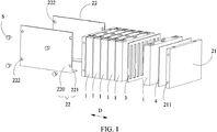
- a battery module comprises: a plurality of mono-batteries 1 arranged along an arrangement direction D; and a frame 2 receiving and fixing the plurality of mono-batteries 1.
- the battery module further comprises a plurality of isolating plates 3, each isolating plate 3 is interposed between two adjacent mono-batteries 1, each isolating plate 1 is provided with a through hole penetrating along the arrangement direction D.
- Each isolating plate 3 is configured to be capable of self-foaming to make a volume of each isolating plate 3 expanded when each isolating plate 3 is heated and a temperature of each isolating plate 3 is more than 200 °C.
- Each isolating plate 3 won't self-foam under normal use (the temperature of each isolating plate 3 is not more than 200 °C), structural integrity of each isolating plate 3 is maintained and an interval between the two adjacent mono-batteries 1 is maintained.
- the through hole of the isolating plate 3 can form air thermal resistance, thereby preventing heat generated by the runaway mono-battery 1 from massively and quickly transferring to large surfaces of the mono-batteries 1 adjacent to the runaway mono-battery 1, so as to achieve the purpose of thermal isolation.
- each isolating plate 3 can self-foam so as to develop pores in the inside of each isolating plate 3, meanwhile, the volume of each isolating plate 3 is expanded, thereby increasing the interval between the two adjacent mono-batteries 1, further increasing the air thermal resistance, preventing heat generated by the runaway mono-battery 1 from transferring to the large surfaces of the mono-batteries 1 adjacent to the runaway mono-battery 1, and avoiding the battery module from being runaway.
- a main component of each isolating plate 3 is thermosetting resin which is capable of self-foaming to make a volume thereof expanded when heated.
- a main component of the isolating plate 3 means that in all components of the isolating plate 3, besides the thermosetting resin which is capable of self-foaming to make the volume thereof expanded when heated is included, other materials, for example conventional resin, polymer, inorganic filler and the like, can also be included.
- the isolating plate 3 may also only be consisted of the thermosetting resin which is capable of self-foaming to make the volume thereof expanded when heated.
- thermosetting resin is one selected from a group consisting of bisphenol-A cyanate ester resin (BCE), complex cyanate ester resin of phenol novolac cyanate ester and bisphenol-A cyanate ester and allyl compound modified bismaleimide resin.
- BCE bisphenol-A cyanate ester resin
- complex cyanate ester resin of phenol novolac cyanate ester and bisphenol-A cyanate ester and allyl compound modified bismaleimide resin.
- the allyl compound may be allylphenol.
- the allyl compound may be 2,2'-diallylbisphenol A (DABPA).
- a compressive strength of each isolating plate 3 is larger than an expansion pressure of the mono-battery 1 adjacent to each isolating plate 3.
- the compressive strength of each isolating plate 3 is 20 MPa - 150 Mpa.
- the compressive strength of each isolating plate 3 is 20 MPa - 150 MPa, even if the mono-battery 1 adjacent to each isolating plate 3 is expanded, each isolating plate 3 won't be compressed, therefore the interval between the two adjacent mono-batteries 1 won't be decreased.
- the compressive strength of each isolating plate 3 is 50 MPa - 150 Mpa.
- the through hole may be provided as one or multiple in number.
- the through hole is provided as multiple in number.
- a shape of the through hole is not limited.
- the shape of the through hole is circular or rectangular.
- a total plane area of the through hole in each isolating plate 3 is 30% - 80% of a total plane area of each isolating plate 3.
- the proportion of the total plane area of the through hole in each isolating plate 3 is larger, heat transfer effect of each isolating plate 3 is worse, thermal isolation effect of each isolating plate 3 is better, but structural strength of each isolating plate 3 is also worse.
- the total plane area of the through hole in each isolating plate 3 is 60% - 70% of the total plane area of each isolating plate 3. It should be noted that, "a total plane area of each isolating plate 3" refers to the total plane area of each isolating plate 3 before the through hole is provided.
- a thickness of each isolating plate 3 is 0.5 mm - 5 mm.
- the thickness of each isolating plate 3 is 2 mm.
- each isolating plate 3 is the same as a large surface of the mono-battery 1 in both length and width.
- a porosity in the inside of each isolating plate 3 is close to 0, and generally is not more than 5%.
- the porosity in the inside of each isolating plate 3 is 10% - 90%.
- a porosity in the inside of each isolating plate 3 refers to the porosity in the inside of a solid portion (that is a portion of each isolating plate 3 except the through hole) of each self-foamed isolating plate 3.
- the frame 2 comprises: two end plates 21 respectively positioned at two ends of the plurality of the mono-batteries 1 along the arrangement direction D; and two side plates 22 respectively positioned at two sides of the plurality of the mono-batteries 1 and perpendicular to the two end plates 21, the two end plates 21 and the two side plates 22 are fixed together.
- each L-type side plate has a vertical portion 220 and a horizontal portion 221; the vertical portion 220 of each side plate 22 and the two end plates 21 are fixed together; the two horizontal portions 221 of the two L-type side plates are spaced apart from each other and contact and support the plurality of mono-batteries 1 and the two end plates 21 from below.
- the L-type side plate helps to form the air thermal resistance in a bottom surface of the battery module, so as to further prevent the heat of the runaway mono-battery 1 from massively and quickly transferring to the mono-batteries 1 adjacent to the runaway mono-battery 1 via the L-type side plate.
- sum of contact areas between the two horizontal portions 221 of the two L-type side plates and the bottom portion of each mono-battery 1 is 5% - 95% of the area of the bottom portion of each mono-battery 1.
- sum of contact areas between the two horizontal portions 221 of the two L-type side plates and the bottom portion of each mono-battery 1 is 40% of the area of the bottom portion of each mono-battery 1.
- the two vertical portions 220 of the two side plates 22 and the two end plates 21 are fixed together via bolts S and/or a structural adhesive.
- each side plate 22 is provided with a plurality of mounting holes 222; each end plate 21 is provided with a plurality of threaded holes 211 corresponding to positions of the plurality of mounting holes 222 of the two vertical portions 220 of the two side plates 22; each bolt S passes through the corresponding mounting hole 222 and is screwed into the corresponding threaded hole 211, therefore the two vertical portions 220 of the two side plates 22 and the two end plates 21 are fixed together.
- the number of the mounting holes 222 may be 4.
- a distance from the mounting hole 222 to a corresponding side edge of the side plate 22 is not less than 4 mm.
- the distance from the mounting hole 222 to the corresponding side edge of the side plate 22 is 5 mm - 10 mm.
- a thread depth of the threaded hole 211 is 3 mm - 30 mm.
- the thread depth of the threaded hole 211 is 5 mm - 10 mm.
- the structural adhesive is one or more selected from a group consisting of epoxy resin, acrylic acid and polyurethane.
- the structural adhesive is acrylic acid.
- a coating thickness of the structural adhesive is 0.2 mm - 2 mm.
- the coating thickness of the structural adhesive is 0.5 mm.
- a thickness of each side plate 22 is 1 mm - 5 mm.
- the thickness of each side plate 22 is 2 mm.
- a material of each of the two side plates 22 is fiber-reinforced thermosetting resin.
- the fiber in the fiber-reinforced thermosetting resin, is one or more selected from a group consisting of glass fiber, carbon fiber, ceramic fiber and Kevlar fiber.
- the fiber is glass fiber.
- the fiber in the fiber-reinforced thermosetting resin, is one or more selected from a group consisting of chopped fiber, fibrous mat and fibrous fabric.
- the fiber is fibrous fabric.
- the thermosetting resin is one or more selected from a group consisting of cyanate ester resin, epoxy resin, epoxy vinyl ester resin and unsaturated polyester resin.
- the thermosetting resin is epoxy vinyl ester resin.
- a thermal conductivity of the fiber-reinforced thermosetting resin is not more than 0.5 W/(mK).
- the battery module further comprises: two insulating plates 4 each provided between one end plate 21 and one mono-battery 1 adjacent to the one end plate 21.
- Length ⁇ width ⁇ thickness of each mono-battery was 150 mm ⁇ 100 mm ⁇ 2 mm, a nominal capacity of each mono-battery was 42 Ah, positive materials of each mono-battery were NCM, then the three mono-batteries were assembled as a 1P3S battery module, each isolating plate was made from allyl compound modified bismaleimide resin, and each isolating plate was provided with a plurality of penetrating through holes, a total plane area of the through holes in each isolating plate was 30% of a total plane area of each isolating plate. Nail penetration test was conducted on the battery module until a puncturing depth of the nail in the first mono-battery was 50% of a thickness of the first mono-battery.
- the highest temperature of the first mono-battery was 500 °C.
- the explosion-proof vent of the second mono-battery was not opened, the voltage remained stable, and the highest temperature was not more than 249.6 °C.
- the highest temperature of the third mono-battery was not more than 60 °C.
- Length ⁇ width ⁇ thickness of each mono-battery was 150 mm ⁇ 100 mm ⁇ 2 mm, a nominal capacity of each mono-battery was 42 Ah, positive materials of each mono-battery were NCM, then the three mono-batteries were assembled as a 1P3S battery module, each isolating plate was a compact plate made from silicone rubber (each isolating plate was not provided with the through hole penetrating along the up-down direction). Nail penetration test was conducted on the battery module until a puncturing depth of the nail in the first mono-battery was 50% of a thickness of the first mono-battery.
- the highest temperature of the first mono-battery was 550 °C.
- the explosion-proof vent of the second mono-battery was opened after 11 min, then the voltage was down to 0 V, and the highest temperature was 580.5 °C.
- the explosion-proof vent of the third mono-battery was opened after 22 min, then the voltage was down to 0 V, the highest temperature was 600.2 °C.
- Length ⁇ width ⁇ thickness of each mono-battery was 150 mm ⁇ 100 mm ⁇ 2 mm, a nominal capacity of each mono-battery was 42 Ah, positive materials of each mono-battery were NCM, then the three mono-batteries were assembled as a 1P3S battery module, each isolating plate was a compact plate made from allyl compound modified bismaleimide resin (each isolating plate was not provided with the through hole penetrating along the up-down direction). Nail penetration test was conducted on the battery module until a puncturing depth of the nail in the first mono-battery was 50% of a thickness of the first mono-battery.
- the highest temperature of the first mono-battery was 542.3 °C.
- the explosion-proof vent of the second mono-battery was opened after 19 min, then the voltage was down to 0 V, and the highest temperature was 561.1 °C.
- the explosion-proof vent of the third mono-battery was opened after 37 min, the voltage was down to 0 V, the highest temperature was 564.5 °C.
Landscapes
- Chemical & Material Sciences (AREA)
- Chemical Kinetics & Catalysis (AREA)
- Electrochemistry (AREA)
- General Chemical & Material Sciences (AREA)
- Engineering & Computer Science (AREA)
- Manufacturing & Machinery (AREA)
- Secondary Cells (AREA)
- Battery Mounting, Suspending (AREA)
Abstract
Description
- The present application claims priority to Chinese patent application No.
CN201610910232.X, filed on October 19, 2016 - The present invention relates to the field of battery, and particularly relates to a battery module.
- In existing structure of a battery module, a side plate has a composite structure consisting of aluminum alloy and an insulating membrane, adjacent mono-batteries directly contact with each other or space apart from each other via a compact plate (such as rubber pad, insulating plastic). When one mono-battery suffers thermal runaway, a temperature of the one mono-battery even reaches 500 °C, at this time, heat generated by the one mono-battery may be massively transferred to mono-batteries adjacent to the one mono-battery respectively via adjacent compact plates and the side plate of metal (such as aluminum alloy), therefore the mono-batteries adjacent to the one mono-battery are also runaway. However, using an aerogel blanket to space apart the adjacent mono-batteries will cost too much.
- In view of the problems existing in the background of the present invention, an object of the present invention is to provide a battery module, in which a through-hole of each isolating plate can form air thermal resistance, thereby preventing heat generated by one runaway mono-battery from massively and quickly transferring to large surfaces of mono-batteries adjacent to the runaway mono-battery, so as to achieve the purpose of thermal isolation.
- In order to achieve the above object, the present invention provides a battery module, which comprises: a plurality of mono-batteries arranged along an arrangement direction; and a frame receiving and fixing the plurality of mono-batteries. The battery module further comprises a plurality of isolating plates, each isolating plate is interposed between two adjacent mono-batteries, each isolating plate is provided with a through hole penetrating along the arrangement direction. Each isolating plate is configured to be capable of self-foaming to make a volume of each isolating plate expanded when each isolating plate is heated and a temperature of each isolating plate is more than 200 °C.
- Compared to the prior art, the present invention has following beneficial effects: in the battery module of the present invention, the through-hole of each isolating plate can form air thermal resistance, because air has a low thermal conductivity, therefore the isolating plate of the present invention can prevent heat generated by the runaway mono-battery from massively and quickly transferring to the large surfaces of the adjacent mono-batteries, so as to achieve the purpose of thermal isolation. At the same time, when the temperature rises and the temperature of each isolating plate is more than 200 °C, each isolating plate can self-foam so as to develop pores in the inside of each isolating plate, meanwhile, the volume of each isolating plate is expanded, thereby further increasing the air thermal resistance, preventing heat generated by the runaway mono-battery from transferring to the large surfaces of the adjacent mono-batteries, and avoiding the battery module from being runaway.
- The battery module of the present invention is especially suitable for application in a power battery and an energy storage battery.
-
-
FIG. 1 is an exploded view of a battery module of the present invention. -
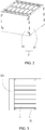
FIG. 2 is an assembled view of the battery module ofFIG. 1 . -
FIG. 3 is an assembled bottom view of the battery module ofFIG. 2 . -
FIG. 4 is an assembled top view of the battery module ofFIG. 2 . -
FIG. 5 is an assembled rear view of the battery module ofFIG. 2 . -
FIG. 6 is an assembled side view of the battery module ofFIG. 2 . - The reference numerals are as follows:
- 1 mono-battery
- 2 frame
- 21 end plate
- 211 threaded hole
- 22 side plate
- 220 vertical portion
- 221 horizontal portion
- 222 mounting hole
- 3 isolating plate
- 4 insulating plate
- S bolt
- D arrangement direction
- Hereinafter a battery module according to the present invention will be described in detail.
- Referring to
FIG. 1 to FIG. 6 , a battery module according to the present invention comprises: a plurality of mono-batteries 1 arranged along an arrangement direction D; and aframe 2 receiving and fixing the plurality of mono-batteries 1. The battery module further comprises a plurality ofisolating plates 3, eachisolating plate 3 is interposed between two adjacent mono-batteries 1, eachisolating plate 1 is provided with a through hole penetrating along the arrangement direction D. Eachisolating plate 3 is configured to be capable of self-foaming to make a volume of eachisolating plate 3 expanded when eachisolating plate 3 is heated and a temperature of eachisolating plate 3 is more than 200 °C. - Each
isolating plate 3 won't self-foam under normal use (the temperature of eachisolating plate 3 is not more than 200 °C), structural integrity of eachisolating plate 3 is maintained and an interval between the two adjacent mono-batteries 1 is maintained. When one mono-battery 1 is runaway and the temperature rises, because air has a low thermal conductivity, the through hole of the isolatingplate 3 can form air thermal resistance, thereby preventing heat generated by the runaway mono-battery 1 from massively and quickly transferring to large surfaces of the mono-batteries 1 adjacent to the runaway mono-battery 1, so as to achieve the purpose of thermal isolation. At the same time, when the temperature rises and the temperature of eachisolating plate 3 is more than 200 °C, eachisolating plate 3 can self-foam so as to develop pores in the inside of eachisolating plate 3, meanwhile, the volume of eachisolating plate 3 is expanded, thereby increasing the interval between the two adjacent mono-batteries 1, further increasing the air thermal resistance, preventing heat generated by the runaway mono-battery 1 from transferring to the large surfaces of the mono-batteries 1 adjacent to the runaway mono-battery 1, and avoiding the battery module from being runaway. - In the battery module according to the present invention, a main component of each
isolating plate 3 is thermosetting resin which is capable of self-foaming to make a volume thereof expanded when heated. It should be noted that, "a main component of theisolating plate 3" means that in all components of theisolating plate 3, besides the thermosetting resin which is capable of self-foaming to make the volume thereof expanded when heated is included, other materials, for example conventional resin, polymer, inorganic filler and the like, can also be included. Of course, theisolating plate 3 may also only be consisted of the thermosetting resin which is capable of self-foaming to make the volume thereof expanded when heated. - In the battery module according to the present invention, the thermosetting resin is one selected from a group consisting of bisphenol-A cyanate ester resin (BCE), complex cyanate ester resin of phenol novolac cyanate ester and bisphenol-A cyanate ester and allyl compound modified bismaleimide resin.
- In the battery module according to the present invention, the allyl compound may be allylphenol. Preferably, the allyl compound may be 2,2'-diallylbisphenol A (DABPA).
- In the battery module according to the present invention, a compressive strength of each
isolating plate 3 is larger than an expansion pressure of the mono-battery 1 adjacent to eachisolating plate 3. - In the battery module according to the present invention, the compressive strength of each
isolating plate 3 is 20 MPa - 150 Mpa. When the compressive strength of eachisolating plate 3 is 20 MPa - 150 MPa, even if the mono-battery 1 adjacent to eachisolating plate 3 is expanded, eachisolating plate 3 won't be compressed, therefore the interval between the two adjacent mono-batteries 1 won't be decreased. Preferably, the compressive strength of eachisolating plate 3 is 50 MPa - 150 Mpa. - In the battery module according to the present invention, the through hole may be provided as one or multiple in number. Preferably, the through hole is provided as multiple in number.
- In the battery module according to the present invention, a shape of the through hole is not limited. Preferably, the shape of the through hole is circular or rectangular.
- In the battery module according to the present invention, a total plane area of the through hole in each
isolating plate 3 is 30% - 80% of a total plane area of eachisolating plate 3. The proportion of the total plane area of the through hole in eachisolating plate 3 is larger, heat transfer effect of eachisolating plate 3 is worse, thermal isolation effect of eachisolating plate 3 is better, but structural strength of eachisolating plate 3 is also worse. Preferably, the total plane area of the through hole in eachisolating plate 3 is 60% - 70% of the total plane area of eachisolating plate 3. It should be noted that, "a total plane area of eachisolating plate 3" refers to the total plane area of eachisolating plate 3 before the through hole is provided. - In the battery module according to the present invention, a thickness of each
isolating plate 3 is 0.5 mm - 5 mm. Preferably, the thickness of eachisolating plate 3 is 2 mm. - In the battery module according to the present invention, each
isolating plate 3 is the same as a large surface of the mono-battery 1 in both length and width. - In the battery module according to the present invention, when the battery module is under normal use, due to restriction of inherent characteristics of a material of each isolating
plate 3, a porosity in the inside of each isolatingplate 3 is close to 0, and generally is not more than 5%. When each isolatingplate 3 is heated and the temperature of each isolatingplate 3 is more than 200 °C and each isolatingplate 3 has been self-foamed, the porosity in the inside of each isolatingplate 3 is 10% - 90%. It should be noted that, "a porosity in the inside of each isolatingplate 3" refers to the porosity in the inside of a solid portion (that is a portion of each isolatingplate 3 except the through hole) of each self-foamed isolatingplate 3. - In the battery module according to the present invention, referring to
FIG. 1 andFIG. 2 , theframe 2 comprises: twoend plates 21 respectively positioned at two ends of the plurality of the mono-batteries 1 along the arrangement direction D; and twoside plates 22 respectively positioned at two sides of the plurality of the mono-batteries 1 and perpendicular to the twoend plates 21, the twoend plates 21 and the twoside plates 22 are fixed together. - In the battery module according to the present invention, the two
side plates 22 each are a L-type side plate. Referring toFIG. 1 , each L-type side plate has avertical portion 220 and ahorizontal portion 221; thevertical portion 220 of eachside plate 22 and the twoend plates 21 are fixed together; the twohorizontal portions 221 of the two L-type side plates are spaced apart from each other and contact and support the plurality of mono-batteries 1 and the twoend plates 21 from below. The L-type side plate helps to form the air thermal resistance in a bottom surface of the battery module, so as to further prevent the heat of the runaway mono-battery 1 from massively and quickly transferring to the mono-batteries 1 adjacent to the runaway mono-battery 1 via the L-type side plate. - In the battery module according to the present invention, sum of contact areas between the two
horizontal portions 221 of the two L-type side plates and the bottom portion of each mono-battery 1 is 5% - 95% of the area of the bottom portion of each mono-battery 1. Preferably, sum of contact areas between the twohorizontal portions 221 of the two L-type side plates and the bottom portion of each mono-battery 1 is 40% of the area of the bottom portion of each mono-battery 1. - In the battery module according to the present invention, the two
vertical portions 220 of the twoside plates 22 and the twoend plates 21 are fixed together via bolts S and/or a structural adhesive. - In the battery module according to the present invention, the
vertical portion 220 of eachside plate 22 is provided with a plurality of mountingholes 222; eachend plate 21 is provided with a plurality of threadedholes 211 corresponding to positions of the plurality of mountingholes 222 of the twovertical portions 220 of the twoside plates 22; each bolt S passes through the corresponding mountinghole 222 and is screwed into the corresponding threadedhole 211, therefore the twovertical portions 220 of the twoside plates 22 and the twoend plates 21 are fixed together. Referring toFIG. 1 ,FIG. 2 andFIG. 5 , the number of the mountingholes 222 may be 4. - In the battery module according to the present invention, a distance from the mounting
hole 222 to a corresponding side edge of theside plate 22 is not less than 4 mm. Preferably, the distance from the mountinghole 222 to the corresponding side edge of theside plate 22 is 5 mm - 10 mm. - In the battery module according to the present invention, a thread depth of the threaded
hole 211 is 3 mm - 30 mm. Preferably, the thread depth of the threadedhole 211 is 5 mm - 10 mm. - In the battery module according to the present invention, the structural adhesive is one or more selected from a group consisting of epoxy resin, acrylic acid and polyurethane. Preferably, the structural adhesive is acrylic acid.
- In the battery module according to the present invention, a coating thickness of the structural adhesive is 0.2 mm - 2 mm. Preferably, the coating thickness of the structural adhesive is 0.5 mm.
- In the battery module according to the present invention, a thickness of each
side plate 22 is 1 mm - 5 mm. Preferably, the thickness of eachside plate 22 is 2 mm. - In the battery module according to the present invention, a material of each of the two
side plates 22 is fiber-reinforced thermosetting resin. - In the battery module according to the present invention, in the fiber-reinforced thermosetting resin, the fiber is one or more selected from a group consisting of glass fiber, carbon fiber, ceramic fiber and Kevlar fiber. Preferably, the fiber is glass fiber.
- In the battery module according to the present invention, in the fiber-reinforced thermosetting resin, the fiber is one or more selected from a group consisting of chopped fiber, fibrous mat and fibrous fabric. Preferably, the fiber is fibrous fabric.
- In the battery module according to the present invention, in the fiber-reinforced thermosetting resin, the thermosetting resin is one or more selected from a group consisting of cyanate ester resin, epoxy resin, epoxy vinyl ester resin and unsaturated polyester resin. Preferably, the thermosetting resin is epoxy vinyl ester resin.
- In the battery module according to the present invention, a thermal conductivity of the fiber-reinforced thermosetting resin is not more than 0.5 W/(mK).
- In the battery module according to the present invention, referring to
FIG. 1 , the battery module further comprises: two insulatingplates 4 each provided between oneend plate 21 and one mono-battery 1 adjacent to the oneend plate 21. - Length × width × thickness of each mono-battery was 150 mm × 100 mm × 2 mm, a nominal capacity of each mono-battery was 42 Ah, positive materials of each mono-battery were NCM, then the three mono-batteries were assembled as a 1P3S battery module, each isolating plate was made from allyl compound modified bismaleimide resin, and each isolating plate was provided with a plurality of penetrating through holes, a total plane area of the through holes in each isolating plate was 30% of a total plane area of each isolating plate. Nail penetration test was conducted on the battery module until a puncturing depth of the nail in the first mono-battery was 50% of a thickness of the first mono-battery.
- The highest temperature of the first mono-battery was 500 °C.
- The explosion-proof vent of the second mono-battery was not opened, the voltage remained stable, and the highest temperature was not more than 249.6 °C.
- The highest temperature of the third mono-battery was not more than 60 °C.
- Length × width × thickness of each mono-battery was 150 mm × 100 mm × 2 mm, a nominal capacity of each mono-battery was 42 Ah, positive materials of each mono-battery were NCM, then the three mono-batteries were assembled as a 1P3S battery module, each isolating plate was a compact plate made from silicone rubber (each isolating plate was not provided with the through hole penetrating along the up-down direction). Nail penetration test was conducted on the battery module until a puncturing depth of the nail in the first mono-battery was 50% of a thickness of the first mono-battery.
- The highest temperature of the first mono-battery was 550 °C.
- The explosion-proof vent of the second mono-battery was opened after 11 min, then the voltage was down to 0 V, and the highest temperature was 580.5 °C.
- The explosion-proof vent of the third mono-battery was opened after 22 min, then the voltage was down to 0 V, the highest temperature was 600.2 °C.
- Length × width × thickness of each mono-battery was 150 mm × 100 mm × 2 mm, a nominal capacity of each mono-battery was 42 Ah, positive materials of each mono-battery were NCM, then the three mono-batteries were assembled as a 1P3S battery module, each isolating plate was a compact plate made from allyl compound modified bismaleimide resin (each isolating plate was not provided with the through hole penetrating along the up-down direction). Nail penetration test was conducted on the battery module until a puncturing depth of the nail in the first mono-battery was 50% of a thickness of the first mono-battery.
- The highest temperature of the first mono-battery was 542.3 °C.
- The explosion-proof vent of the second mono-battery was opened after 19 min, then the voltage was down to 0 V, and the highest temperature was 561.1 °C.
- The explosion-proof vent of the third mono-battery was opened after 37 min, the voltage was down to 0 V, the highest temperature was 564.5 °C.
Claims (13)
- A battery module, comprising:a plurality of mono-batteries arranged along an arrangement direction; anda frame receiving and fixing the plurality of mono-batteries;whereinthe battery module further comprises a plurality of isolating plates, each isolating plate is interposed between two adjacent mono-batteries, each isolating plate is provided with a through hole penetrating along the arrangement direction;each isolating plate is configured to be capable of self-foaming to make a volume of each isolating plate expanded when each isolating plate is heated and a temperature of each isolating plate is more than 200 °C.
- The battery module according to Claim 1, wherein a main component of each isolating plate is thermosetting resin which is capable of self-foaming to make a volume thereof expanded when heated.
- The battery module according to Claim 2, wherein the thermosetting resin is one selected from a group consisting of bisphenol-A cyanate ester resin, complex cyanate ester resin of phenol novolac cyanate ester and bisphenol-A cyanate ester and allyl compound modified bismaleimide resin.
- The battery module according to Claim 3, wherein the allyl compound is 2,2'-diallylbisphenol A.
- The battery module according to Claim 1, wherein a compressive strength of each isolating plate is larger than an expansion pressure of the mono-battery adjacent to each isolating plate.
- The battery module according to Claim 1, wherein a compressive strength of each isolating plate is 20 MPa - 150 Mpa.
- The battery module according to Claim 6, wherein the compressive strength of each isolating plate is 50 MPa - 150 Mpa.
- The battery module according to Claim 1, wherein the through hole is provided as one or multiple in number.
- The battery module according to Claim 8, wherein the through hole is provided as multiple in number.
- The battery module according to Claim 1, wherein a total plane area of the through hole in each isolating plate is 30% - 80% of a total plane area of each isolating plate.
- The battery module according to Claim 10, wherein the total plane area of the through hole in each isolating plate is 60% - 70% of the total plane area of each isolating plate.
- The battery module according to Claim 1, wherein when each isolating plate is heated and the temperature of each isolating plate is more than 200 °C and each isolating plate has been self-foamed, a porosity in the inside of each isolating plate is 10% - 90%.
- The battery module according to Claim 1, wherein the frame comprises:two end plates respectively positioned at two ends of the plurality of the mono-batteries along the arrangement direction; andtwo side plates respectively positioned at two sides of the plurality of the mono-batteries and perpendicular to the two end plates, the two end plates and the two side plates are fixed together;the two side plates each are a L-type side plate;each L-type side plate has a vertical portion and a horizontal portion;the vertical portion of each side plate and the two end plates are fixed together;the two horizontal portions of the two L-type side plates are spaced apart from each other and contact and support the plurality of mono-batteries and the two end plates from below.
Priority Applications (1)
| Application Number | Priority Date | Filing Date | Title |
|---|---|---|---|
| PL17194880T PL3312931T3 (en) | 2016-10-19 | 2017-10-05 | Battery module |
Applications Claiming Priority (1)
| Application Number | Priority Date | Filing Date | Title |
|---|---|---|---|
| CN201610910232.XA CN107968168B (en) | 2016-10-19 | 2016-10-19 | Battery module |
Publications (2)
| Publication Number | Publication Date |
|---|---|
| EP3312931A1 true EP3312931A1 (en) | 2018-04-25 |
| EP3312931B1 EP3312931B1 (en) | 2020-04-29 |
Family
ID=60021964
Family Applications (1)
| Application Number | Title | Priority Date | Filing Date |
|---|---|---|---|
| EP17194880.5A Active EP3312931B1 (en) | 2016-10-19 | 2017-10-05 | Battery module |
Country Status (4)
| Country | Link |
|---|---|
| US (1) | US10686171B2 (en) |
| EP (1) | EP3312931B1 (en) |
| CN (1) | CN107968168B (en) |
| PL (1) | PL3312931T3 (en) |
Cited By (2)
| Publication number | Priority date | Publication date | Assignee | Title |
|---|---|---|---|---|
| CN112154552A (en) * | 2019-03-25 | 2020-12-29 | 株式会社Lg化学 | Battery module, battery rack including battery module, and energy storage system |
| WO2021233838A1 (en) | 2020-05-19 | 2021-11-25 | Basf Se | Metal polymer laminate structure |
Families Citing this family (19)
| Publication number | Priority date | Publication date | Assignee | Title |
|---|---|---|---|---|
| KR102716343B1 (en) * | 2018-05-25 | 2024-10-14 | 주식회사 엘지에너지솔루션 | Battery housing and battery module including the same |
| KR102585988B1 (en) * | 2018-06-20 | 2023-10-05 | 주식회사 엘지에너지솔루션 | Battery module, battery pack comprising the battery module and vehicle comprising the battery pack |
| CN109004111A (en) * | 2018-08-08 | 2018-12-14 | 威艾能源(惠州)有限公司 | A kind of battery pack for preventing thermal failure from spreading |
| CN110265591B (en) | 2018-08-31 | 2020-01-24 | 宁德时代新能源科技股份有限公司 | battery module |
| WO2020077333A1 (en) | 2018-10-12 | 2020-04-16 | Ppg Industries Ohio, Inc. | Compositions containing thermally conductive fillers |
| CN209344217U (en) * | 2019-02-27 | 2019-09-03 | 宁德时代新能源科技股份有限公司 | Battery modules and battery pack |
| CN110190221B (en) * | 2019-05-14 | 2020-09-04 | 宁德时代新能源科技股份有限公司 | Battery Modules and Battery Packs |
| CN211017166U (en) * | 2019-11-15 | 2020-07-14 | 宁德时代新能源科技股份有限公司 | Separator panels, battery modules, battery packs and devices |
| KR102932319B1 (en) * | 2020-02-27 | 2026-02-26 | 주식회사 엘지에너지솔루션 | Battery Pack, Battery Rack Comprising The Same, And Power Storage System |
| CN111584979A (en) * | 2020-06-22 | 2020-08-25 | 昆山宝创新能源科技有限公司 | Battery module |
| CN111584791A (en) * | 2020-06-22 | 2020-08-25 | 昆山宝创新能源科技有限公司 | Battery module |
| CN111834575A (en) * | 2020-07-31 | 2020-10-27 | 昆山宝创新能源科技有限公司 | Battery module and its flame retardant heat shield |
| CN112151918B (en) * | 2020-09-24 | 2022-05-06 | 合肥国轩高科动力能源有限公司 | A kind of thermal insulation film and its preparation method and application |
| DE102021113419A1 (en) * | 2021-05-25 | 2022-12-01 | Lisa Dräxlmaier GmbH | BATTERY MODULE FOR AN ELECTRIC VEHICLE TRACTION BATTERY |
| JP7361069B2 (en) * | 2021-05-28 | 2023-10-13 | プライムプラネットエナジー&ソリューションズ株式会社 | An assembled battery spacer and an assembled battery equipped with the assembled battery spacer |
| CN114335866A (en) * | 2021-12-22 | 2022-04-12 | 重庆长安新能源汽车科技有限公司 | Battery module for preventing thermal runaway propagation |
| EP4287359A1 (en) | 2022-05-30 | 2023-12-06 | Newfrey LLC | Thermal fin for a battery apparatus and battery module comprising thermal fins |
| DE212024000310U1 (en) * | 2024-06-28 | 2026-02-03 | Contemporary Amperex Technology Co., Limited | Battery and power-consuming device |
| GB2642878A (en) * | 2024-07-24 | 2026-01-28 | Mercedes Benz Group Ag | A battery module for an electrical energy storage device of a motor vehicle, an electrical energy storage device and a method |
Citations (7)
| Publication number | Priority date | Publication date | Assignee | Title |
|---|---|---|---|---|
| US20100136385A1 (en) * | 2009-07-17 | 2010-06-03 | Tesla Motors, Inc. | Method and apparatus for maintaining cell wall integrity during thermal runaway using an outer layer of intumescent material |
| US20120316313A1 (en) * | 2011-06-07 | 2012-12-13 | Todd Emrick | Halogen-free flame retarding materials based on bisphenol triazole resins and polymers |
| DE202013001662U1 (en) * | 2012-02-20 | 2013-03-07 | Graftech International Holdings Inc. | Composite heat spreader and this comprehensive battery module |
| DE102013200546A1 (en) * | 2013-01-16 | 2014-07-17 | Hilti Aktiengesellschaft | Accumulator for a hand tool and method for producing a rechargeable battery for a hand tool |
| US20150221914A1 (en) * | 2014-02-03 | 2015-08-06 | Pyrophobic Systems, Ltd. | Intumescent Battery Housing |
| DE102015206182A1 (en) * | 2014-05-06 | 2015-11-12 | Robert Bosch Gmbh | Isolating contiguous lithium-ion batteries by complete encapsulation / pouring of the container in a device |
| JP2016046163A (en) * | 2014-08-25 | 2016-04-04 | 三菱重工業株式会社 | Battery module and module cover |
Family Cites Families (13)
| Publication number | Priority date | Publication date | Assignee | Title |
|---|---|---|---|---|
| JP2009021223A (en) * | 2007-06-11 | 2009-01-29 | Panasonic Corp | Battery pack and battery-equipped equipment |
| JP5326480B2 (en) * | 2008-10-14 | 2013-10-30 | トヨタ自動車株式会社 | Power storage device |
| CN102117945A (en) | 2009-12-31 | 2011-07-06 | 财团法人工业技术研究院 | Heat dissipation and thermal runaway diffusion protection structure in battery system |
| JP2011175743A (en) * | 2010-02-23 | 2011-09-08 | Sanyo Electric Co Ltd | Power source apparatus, and vehicle equipped with the same |
| EP2555276A1 (en) * | 2010-03-30 | 2013-02-06 | Panasonic Corporation | Battery pack |
| CN102796283B (en) * | 2012-09-05 | 2014-01-01 | 苏州大学 | A kind of composite intumescent flame retardant and preparation method thereof |
| CN102838779B (en) * | 2012-09-18 | 2014-02-26 | 苏州大学 | A kind of composite expansion flame retardant modified thermosetting resin and preparation method thereof |
| JPWO2014132649A1 (en) * | 2013-02-27 | 2017-02-02 | 三洋電機株式会社 | Battery module |
| EP2961787A1 (en) | 2013-02-28 | 2016-01-06 | Basf Se | Polyamines and method for the production thereof |
| CN203932256U (en) | 2013-12-17 | 2014-11-05 | 天津力神电池股份有限公司 | The battery modules that possesses forced heat radiation function |
| CN104852087B (en) | 2015-04-15 | 2017-03-01 | 宁德时代新能源科技股份有限公司 | Electrolyte additive and lithium ion battery using same |
| CN204809283U (en) * | 2015-07-08 | 2015-11-25 | 宁德时代新能源科技有限公司 | Battery module |
| CN106099184A (en) | 2016-06-28 | 2016-11-09 | 宁德新能源科技有限公司 | A kind of electrolyte and use the lithium ion battery of this electrolyte |
-
2016
- 2016-10-19 CN CN201610910232.XA patent/CN107968168B/en active Active
-
2017
- 2017-10-05 EP EP17194880.5A patent/EP3312931B1/en active Active
- 2017-10-05 PL PL17194880T patent/PL3312931T3/en unknown
- 2017-10-11 US US15/730,489 patent/US10686171B2/en active Active
Patent Citations (8)
| Publication number | Priority date | Publication date | Assignee | Title |
|---|---|---|---|---|
| US20100136385A1 (en) * | 2009-07-17 | 2010-06-03 | Tesla Motors, Inc. | Method and apparatus for maintaining cell wall integrity during thermal runaway using an outer layer of intumescent material |
| US20120316313A1 (en) * | 2011-06-07 | 2012-12-13 | Todd Emrick | Halogen-free flame retarding materials based on bisphenol triazole resins and polymers |
| DE202013001662U1 (en) * | 2012-02-20 | 2013-03-07 | Graftech International Holdings Inc. | Composite heat spreader and this comprehensive battery module |
| DE102013200546A1 (en) * | 2013-01-16 | 2014-07-17 | Hilti Aktiengesellschaft | Accumulator for a hand tool and method for producing a rechargeable battery for a hand tool |
| EP2946425A1 (en) * | 2013-01-16 | 2015-11-25 | Hilti Aktiengesellschaft | Accumulator provided with fire-retardant properties for a handheld power tool, and method for producing same |
| US20150221914A1 (en) * | 2014-02-03 | 2015-08-06 | Pyrophobic Systems, Ltd. | Intumescent Battery Housing |
| DE102015206182A1 (en) * | 2014-05-06 | 2015-11-12 | Robert Bosch Gmbh | Isolating contiguous lithium-ion batteries by complete encapsulation / pouring of the container in a device |
| JP2016046163A (en) * | 2014-08-25 | 2016-04-04 | 三菱重工業株式会社 | Battery module and module cover |
Cited By (3)
| Publication number | Priority date | Publication date | Assignee | Title |
|---|---|---|---|---|
| CN112154552A (en) * | 2019-03-25 | 2020-12-29 | 株式会社Lg化学 | Battery module, battery rack including battery module, and energy storage system |
| US11942617B2 (en) | 2019-03-25 | 2024-03-26 | Lg Energy Solution, Ltd. | Battery module, and battery rack and energy storage system including the same |
| WO2021233838A1 (en) | 2020-05-19 | 2021-11-25 | Basf Se | Metal polymer laminate structure |
Also Published As
| Publication number | Publication date |
|---|---|
| US20180108888A1 (en) | 2018-04-19 |
| US10686171B2 (en) | 2020-06-16 |
| PL3312931T3 (en) | 2020-11-02 |
| CN107968168A (en) | 2018-04-27 |
| EP3312931B1 (en) | 2020-04-29 |
| CN107968168B (en) | 2020-09-11 |
Similar Documents
| Publication | Publication Date | Title |
|---|---|---|
| EP3312931B1 (en) | Battery module | |
| CN104763100B (en) | Big plate of shelter with radar invisible and bulletproof function and preparation method thereof | |
| US10086581B2 (en) | Carbon fiber composite material | |
| CN205828488U (en) | Battery end plate and battery module | |
| JP6571000B2 (en) | Thermally conductive composite and method for producing the same | |
| WO2023231957A1 (en) | Battery protection bottom plate, composite protection structure for battery pack, and vehicle | |
| US7752955B2 (en) | Methods and systems for fabrication of composite armor laminates by preform stitching | |
| US20180260003A1 (en) | Electronic device housing | |
| CN104763099B (en) | Big plate of shelter with radar invisible function and preparation method thereof | |
| US20040009728A1 (en) | Composite material, formed product and prepreg | |
| CN217788608U (en) | A battery protection bottom plate, battery pack composite protection structure and vehicle | |
| US12237525B2 (en) | Battery or electrochemical cell fixture | |
| KR101379323B1 (en) | End plate for redox flow battery | |
| CN109049865A (en) | A kind of Three-dimensional Heat-transfer channel composite material and preparation method | |
| KR20200043682A (en) | Composite material for battery pack case | |
| CN103587159A (en) | Honeycomb sandwich panel and making method thereof | |
| CN105882014B (en) | A kind of environmental protection combination S MC plate | |
| JP2006130734A (en) | Honeycomb sandwich panel and its manufacturing method | |
| CN205159445U (en) | Lithium ion battery and including this lithium ion battery's car | |
| JP2018187830A (en) | Damping material | |
| CN207638006U (en) | 3 D electromagnetic Meta Materials | |
| CN201152338Y (en) | FRP reinforced rubber vibration isolator | |
| CN213401419U (en) | Battery with a battery cell | |
| CN108963139B (en) | Combined side plate of battery module and battery module | |
| CN203567287U (en) | Honeycomb sandwich panel |
Legal Events
| Date | Code | Title | Description |
|---|---|---|---|
| PUAI | Public reference made under article 153(3) epc to a published international application that has entered the european phase |
Free format text: ORIGINAL CODE: 0009012 |
|
| STAA | Information on the status of an ep patent application or granted ep patent |
Free format text: STATUS: REQUEST FOR EXAMINATION WAS MADE |
|
| 17P | Request for examination filed |
Effective date: 20171005 |
|
| AK | Designated contracting states |
Kind code of ref document: A1 Designated state(s): AL AT BE BG CH CY CZ DE DK EE ES FI FR GB GR HR HU IE IS IT LI LT LU LV MC MK MT NL NO PL PT RO RS SE SI SK SM TR |
|
| AX | Request for extension of the european patent |
Extension state: BA ME |
|
| STAA | Information on the status of an ep patent application or granted ep patent |
Free format text: STATUS: EXAMINATION IS IN PROGRESS |
|
| 17Q | First examination report despatched |
Effective date: 20190227 |
|
| RIC1 | Information provided on ipc code assigned before grant |
Ipc: H01M 2/10 20060101ALN20191007BHEP Ipc: H01M 10/658 20140101ALI20191007BHEP Ipc: H01M 10/647 20140101AFI20191007BHEP |
|
| GRAP | Despatch of communication of intention to grant a patent |
Free format text: ORIGINAL CODE: EPIDOSNIGR1 |
|
| STAA | Information on the status of an ep patent application or granted ep patent |
Free format text: STATUS: GRANT OF PATENT IS INTENDED |
|
| INTG | Intention to grant announced |
Effective date: 20191118 |
|
| GRAS | Grant fee paid |
Free format text: ORIGINAL CODE: EPIDOSNIGR3 |
|
| GRAA | (expected) grant |
Free format text: ORIGINAL CODE: 0009210 |
|
| STAA | Information on the status of an ep patent application or granted ep patent |
Free format text: STATUS: THE PATENT HAS BEEN GRANTED |
|
| AK | Designated contracting states |
Kind code of ref document: B1 Designated state(s): AL AT BE BG CH CY CZ DE DK EE ES FI FR GB GR HR HU IE IS IT LI LT LU LV MC MK MT NL NO PL PT RO RS SE SI SK SM TR |
|
| REG | Reference to a national code |
Ref country code: GB Ref legal event code: FG4D |
|
| REG | Reference to a national code |
Ref country code: CH Ref legal event code: EP |
|
| REG | Reference to a national code |
Ref country code: AT Ref legal event code: REF Ref document number: 1264676 Country of ref document: AT Kind code of ref document: T Effective date: 20200515 |
|
| REG | Reference to a national code |
Ref country code: DE Ref legal event code: R096 Ref document number: 602017015580 Country of ref document: DE |
|
| REG | Reference to a national code |
Ref country code: IE Ref legal event code: FG4D |
|
| REG | Reference to a national code |
Ref country code: NL Ref legal event code: FP |
|
| REG | Reference to a national code |
Ref country code: LT Ref legal event code: MG4D |
|
| PG25 | Lapsed in a contracting state [announced via postgrant information from national office to epo] |
Ref country code: GR Free format text: LAPSE BECAUSE OF FAILURE TO SUBMIT A TRANSLATION OF THE DESCRIPTION OR TO PAY THE FEE WITHIN THE PRESCRIBED TIME-LIMIT Effective date: 20200730 Ref country code: LT Free format text: LAPSE BECAUSE OF FAILURE TO SUBMIT A TRANSLATION OF THE DESCRIPTION OR TO PAY THE FEE WITHIN THE PRESCRIBED TIME-LIMIT Effective date: 20200429 Ref country code: FI Free format text: LAPSE BECAUSE OF FAILURE TO SUBMIT A TRANSLATION OF THE DESCRIPTION OR TO PAY THE FEE WITHIN THE PRESCRIBED TIME-LIMIT Effective date: 20200429 Ref country code: NO Free format text: LAPSE BECAUSE OF FAILURE TO SUBMIT A TRANSLATION OF THE DESCRIPTION OR TO PAY THE FEE WITHIN THE PRESCRIBED TIME-LIMIT Effective date: 20200729 Ref country code: IS Free format text: LAPSE BECAUSE OF FAILURE TO SUBMIT A TRANSLATION OF THE DESCRIPTION OR TO PAY THE FEE WITHIN THE PRESCRIBED TIME-LIMIT Effective date: 20200829 Ref country code: SE Free format text: LAPSE BECAUSE OF FAILURE TO SUBMIT A TRANSLATION OF THE DESCRIPTION OR TO PAY THE FEE WITHIN THE PRESCRIBED TIME-LIMIT Effective date: 20200429 Ref country code: PT Free format text: LAPSE BECAUSE OF FAILURE TO SUBMIT A TRANSLATION OF THE DESCRIPTION OR TO PAY THE FEE WITHIN THE PRESCRIBED TIME-LIMIT Effective date: 20200831 |
|
| REG | Reference to a national code |
Ref country code: AT Ref legal event code: MK05 Ref document number: 1264676 Country of ref document: AT Kind code of ref document: T Effective date: 20200429 |
|
| PG25 | Lapsed in a contracting state [announced via postgrant information from national office to epo] |
Ref country code: HR Free format text: LAPSE BECAUSE OF FAILURE TO SUBMIT A TRANSLATION OF THE DESCRIPTION OR TO PAY THE FEE WITHIN THE PRESCRIBED TIME-LIMIT Effective date: 20200429 Ref country code: LV Free format text: LAPSE BECAUSE OF FAILURE TO SUBMIT A TRANSLATION OF THE DESCRIPTION OR TO PAY THE FEE WITHIN THE PRESCRIBED TIME-LIMIT Effective date: 20200429 Ref country code: BG Free format text: LAPSE BECAUSE OF FAILURE TO SUBMIT A TRANSLATION OF THE DESCRIPTION OR TO PAY THE FEE WITHIN THE PRESCRIBED TIME-LIMIT Effective date: 20200729 Ref country code: RS Free format text: LAPSE BECAUSE OF FAILURE TO SUBMIT A TRANSLATION OF THE DESCRIPTION OR TO PAY THE FEE WITHIN THE PRESCRIBED TIME-LIMIT Effective date: 20200429 |
|
| PG25 | Lapsed in a contracting state [announced via postgrant information from national office to epo] |
Ref country code: AL Free format text: LAPSE BECAUSE OF FAILURE TO SUBMIT A TRANSLATION OF THE DESCRIPTION OR TO PAY THE FEE WITHIN THE PRESCRIBED TIME-LIMIT Effective date: 20200429 |
|
| PG25 | Lapsed in a contracting state [announced via postgrant information from national office to epo] |
Ref country code: EE Free format text: LAPSE BECAUSE OF FAILURE TO SUBMIT A TRANSLATION OF THE DESCRIPTION OR TO PAY THE FEE WITHIN THE PRESCRIBED TIME-LIMIT Effective date: 20200429 Ref country code: SM Free format text: LAPSE BECAUSE OF FAILURE TO SUBMIT A TRANSLATION OF THE DESCRIPTION OR TO PAY THE FEE WITHIN THE PRESCRIBED TIME-LIMIT Effective date: 20200429 Ref country code: CZ Free format text: LAPSE BECAUSE OF FAILURE TO SUBMIT A TRANSLATION OF THE DESCRIPTION OR TO PAY THE FEE WITHIN THE PRESCRIBED TIME-LIMIT Effective date: 20200429 Ref country code: RO Free format text: LAPSE BECAUSE OF FAILURE TO SUBMIT A TRANSLATION OF THE DESCRIPTION OR TO PAY THE FEE WITHIN THE PRESCRIBED TIME-LIMIT Effective date: 20200429 Ref country code: ES Free format text: LAPSE BECAUSE OF FAILURE TO SUBMIT A TRANSLATION OF THE DESCRIPTION OR TO PAY THE FEE WITHIN THE PRESCRIBED TIME-LIMIT Effective date: 20200429 Ref country code: AT Free format text: LAPSE BECAUSE OF FAILURE TO SUBMIT A TRANSLATION OF THE DESCRIPTION OR TO PAY THE FEE WITHIN THE PRESCRIBED TIME-LIMIT Effective date: 20200429 Ref country code: DK Free format text: LAPSE BECAUSE OF FAILURE TO SUBMIT A TRANSLATION OF THE DESCRIPTION OR TO PAY THE FEE WITHIN THE PRESCRIBED TIME-LIMIT Effective date: 20200429 |
|
| REG | Reference to a national code |
Ref country code: DE Ref legal event code: R097 Ref document number: 602017015580 Country of ref document: DE |
|
| PG25 | Lapsed in a contracting state [announced via postgrant information from national office to epo] |
Ref country code: SK Free format text: LAPSE BECAUSE OF FAILURE TO SUBMIT A TRANSLATION OF THE DESCRIPTION OR TO PAY THE FEE WITHIN THE PRESCRIBED TIME-LIMIT Effective date: 20200429 |
|
| PLBE | No opposition filed within time limit |
Free format text: ORIGINAL CODE: 0009261 |
|
| STAA | Information on the status of an ep patent application or granted ep patent |
Free format text: STATUS: NO OPPOSITION FILED WITHIN TIME LIMIT |
|
| 26N | No opposition filed |
Effective date: 20210201 |
|
| PG25 | Lapsed in a contracting state [announced via postgrant information from national office to epo] |
Ref country code: SI Free format text: LAPSE BECAUSE OF FAILURE TO SUBMIT A TRANSLATION OF THE DESCRIPTION OR TO PAY THE FEE WITHIN THE PRESCRIBED TIME-LIMIT Effective date: 20200429 |
|
| REG | Reference to a national code |
Ref country code: CH Ref legal event code: PL |
|
| PG25 | Lapsed in a contracting state [announced via postgrant information from national office to epo] |
Ref country code: LU Free format text: LAPSE BECAUSE OF NON-PAYMENT OF DUE FEES Effective date: 20201005 Ref country code: MC Free format text: LAPSE BECAUSE OF FAILURE TO SUBMIT A TRANSLATION OF THE DESCRIPTION OR TO PAY THE FEE WITHIN THE PRESCRIBED TIME-LIMIT Effective date: 20200429 |
|
| REG | Reference to a national code |
Ref country code: BE Ref legal event code: MM Effective date: 20201031 |
|
| PG25 | Lapsed in a contracting state [announced via postgrant information from national office to epo] |
Ref country code: CH Free format text: LAPSE BECAUSE OF NON-PAYMENT OF DUE FEES Effective date: 20201031 Ref country code: BE Free format text: LAPSE BECAUSE OF NON-PAYMENT OF DUE FEES Effective date: 20201031 Ref country code: LI Free format text: LAPSE BECAUSE OF NON-PAYMENT OF DUE FEES Effective date: 20201031 |
|
| PG25 | Lapsed in a contracting state [announced via postgrant information from national office to epo] |
Ref country code: IE Free format text: LAPSE BECAUSE OF NON-PAYMENT OF DUE FEES Effective date: 20201005 |
|
| PG25 | Lapsed in a contracting state [announced via postgrant information from national office to epo] |
Ref country code: TR Free format text: LAPSE BECAUSE OF FAILURE TO SUBMIT A TRANSLATION OF THE DESCRIPTION OR TO PAY THE FEE WITHIN THE PRESCRIBED TIME-LIMIT Effective date: 20200429 Ref country code: MT Free format text: LAPSE BECAUSE OF FAILURE TO SUBMIT A TRANSLATION OF THE DESCRIPTION OR TO PAY THE FEE WITHIN THE PRESCRIBED TIME-LIMIT Effective date: 20200429 Ref country code: CY Free format text: LAPSE BECAUSE OF FAILURE TO SUBMIT A TRANSLATION OF THE DESCRIPTION OR TO PAY THE FEE WITHIN THE PRESCRIBED TIME-LIMIT Effective date: 20200429 |
|
| PG25 | Lapsed in a contracting state [announced via postgrant information from national office to epo] |
Ref country code: MK Free format text: LAPSE BECAUSE OF FAILURE TO SUBMIT A TRANSLATION OF THE DESCRIPTION OR TO PAY THE FEE WITHIN THE PRESCRIBED TIME-LIMIT Effective date: 20200429 |
|
| P01 | Opt-out of the competence of the unified patent court (upc) registered |
Effective date: 20230516 |
|
| REG | Reference to a national code |
Ref country code: DE Ref legal event code: R082 Ref document number: 602017015580 Country of ref document: DE Ref country code: DE Ref legal event code: R081 Ref document number: 602017015580 Country of ref document: DE Owner name: CONTEMPORARY AMPEREX TECHNOLOGY (HONG KONG) LT, HK Free format text: FORMER OWNER: CONTEMPORARY AMPEREX TECHNOLOGY CO., LIMITED, CITY FUJIAN, JIAOCHENG DISTRICT NINGDE, CN |
|
| REG | Reference to a national code |
Ref country code: NL Ref legal event code: PD Owner name: CONTEMPORARY AMPEREX TECHNOLOGY (HONG KONG) LIMITED; CN Free format text: DETAILS ASSIGNMENT: CHANGE OF OWNER(S), ASSIGNMENT; FORMER OWNER NAME: CONTEMPORARY AMPEREX TECHNOLOGY CO., LIMITED Effective date: 20240819 Ref country code: GB Ref legal event code: 732E Free format text: REGISTERED BETWEEN 20240801 AND 20240807 |
|
| PGFP | Annual fee paid to national office [announced via postgrant information from national office to epo] |
Ref country code: NL Payment date: 20250814 Year of fee payment: 9 |
|
| PGFP | Annual fee paid to national office [announced via postgrant information from national office to epo] |
Ref country code: PL Payment date: 20250714 Year of fee payment: 9 Ref country code: IT Payment date: 20250922 Year of fee payment: 9 |
|
| PGFP | Annual fee paid to national office [announced via postgrant information from national office to epo] |
Ref country code: GB Payment date: 20250814 Year of fee payment: 9 |
|
| PGFP | Annual fee paid to national office [announced via postgrant information from national office to epo] |
Ref country code: FR Payment date: 20250808 Year of fee payment: 9 |
|
| PGFP | Annual fee paid to national office [announced via postgrant information from national office to epo] |
Ref country code: DE Payment date: 20250813 Year of fee payment: 9 |