EP3312924A1 - Flange assembly for use with a solid oxide fuel cell system - Google Patents
Flange assembly for use with a solid oxide fuel cell system Download PDFInfo
- Publication number
- EP3312924A1 EP3312924A1 EP17194596.7A EP17194596A EP3312924A1 EP 3312924 A1 EP3312924 A1 EP 3312924A1 EP 17194596 A EP17194596 A EP 17194596A EP 3312924 A1 EP3312924 A1 EP 3312924A1
- Authority
- EP
- European Patent Office
- Prior art keywords
- flange
- sofc
- cylindrical surface
- flange assembly
- dielectric element
- Prior art date
- Legal status (The legal status is an assumption and is not a legal conclusion. Google has not performed a legal analysis and makes no representation as to the accuracy of the status listed.)
- Granted
Links
Images




Classifications
-
- H—ELECTRICITY
- H01—ELECTRIC ELEMENTS
- H01M—PROCESSES OR MEANS, e.g. BATTERIES, FOR THE DIRECT CONVERSION OF CHEMICAL ENERGY INTO ELECTRICAL ENERGY
- H01M8/00—Fuel cells; Manufacture thereof
- H01M8/04—Auxiliary arrangements, e.g. for control of pressure or for circulation of fluids
- H01M8/04082—Arrangements for control of reactant parameters, e.g. pressure or concentration
- H01M8/04201—Reactant storage and supply, e.g. means for feeding, pipes
-
- H—ELECTRICITY
- H01—ELECTRIC ELEMENTS
- H01M—PROCESSES OR MEANS, e.g. BATTERIES, FOR THE DIRECT CONVERSION OF CHEMICAL ENERGY INTO ELECTRICAL ENERGY
- H01M8/00—Fuel cells; Manufacture thereof
- H01M8/24—Grouping of fuel cells, e.g. stacking of fuel cells
- H01M8/2465—Details of groupings of fuel cells
- H01M8/2484—Details of groupings of fuel cells characterised by external manifolds
- H01M8/2485—Arrangements for sealing external manifolds; Arrangements for mounting external manifolds around a stack
-
- H—ELECTRICITY
- H01—ELECTRIC ELEMENTS
- H01M—PROCESSES OR MEANS, e.g. BATTERIES, FOR THE DIRECT CONVERSION OF CHEMICAL ENERGY INTO ELECTRICAL ENERGY
- H01M8/00—Fuel cells; Manufacture thereof
- H01M8/24—Grouping of fuel cells, e.g. stacking of fuel cells
- H01M8/2465—Details of groupings of fuel cells
-
- F—MECHANICAL ENGINEERING; LIGHTING; HEATING; WEAPONS; BLASTING
- F16—ENGINEERING ELEMENTS AND UNITS; GENERAL MEASURES FOR PRODUCING AND MAINTAINING EFFECTIVE FUNCTIONING OF MACHINES OR INSTALLATIONS; THERMAL INSULATION IN GENERAL
- F16L—PIPES; JOINTS OR FITTINGS FOR PIPES; SUPPORTS FOR PIPES, CABLES OR PROTECTIVE TUBING; MEANS FOR THERMAL INSULATION IN GENERAL
- F16L25/00—Construction or details of pipe joints not provided for in, or of interest apart from, groups F16L13/00 - F16L23/00
- F16L25/0072—Joints for pipes of dissimilar materials
-
- F—MECHANICAL ENGINEERING; LIGHTING; HEATING; WEAPONS; BLASTING
- F16—ENGINEERING ELEMENTS AND UNITS; GENERAL MEASURES FOR PRODUCING AND MAINTAINING EFFECTIVE FUNCTIONING OF MACHINES OR INSTALLATIONS; THERMAL INSULATION IN GENERAL
- F16L—PIPES; JOINTS OR FITTINGS FOR PIPES; SUPPORTS FOR PIPES, CABLES OR PROTECTIVE TUBING; MEANS FOR THERMAL INSULATION IN GENERAL
- F16L25/00—Construction or details of pipe joints not provided for in, or of interest apart from, groups F16L13/00 - F16L23/00
- F16L25/02—Construction or details of pipe joints not provided for in, or of interest apart from, groups F16L13/00 - F16L23/00 specially adapted for electrically insulating the two pipe ends of the joint from each other
- F16L25/026—Construction or details of pipe joints not provided for in, or of interest apart from, groups F16L13/00 - F16L23/00 specially adapted for electrically insulating the two pipe ends of the joint from each other for flanged joints
-
- F—MECHANICAL ENGINEERING; LIGHTING; HEATING; WEAPONS; BLASTING
- F16—ENGINEERING ELEMENTS AND UNITS; GENERAL MEASURES FOR PRODUCING AND MAINTAINING EFFECTIVE FUNCTIONING OF MACHINES OR INSTALLATIONS; THERMAL INSULATION IN GENERAL
- F16L—PIPES; JOINTS OR FITTINGS FOR PIPES; SUPPORTS FOR PIPES, CABLES OR PROTECTIVE TUBING; MEANS FOR THERMAL INSULATION IN GENERAL
- F16L55/00—Devices or appurtenances for use in, or in connection with, pipes or pipe systems
- F16L55/24—Preventing accumulation of dirt or other matter in pipes, e.g. by traps, by strainers
-
- H—ELECTRICITY
- H01—ELECTRIC ELEMENTS
- H01M—PROCESSES OR MEANS, e.g. BATTERIES, FOR THE DIRECT CONVERSION OF CHEMICAL ENERGY INTO ELECTRICAL ENERGY
- H01M8/00—Fuel cells; Manufacture thereof
- H01M8/04—Auxiliary arrangements, e.g. for control of pressure or for circulation of fluids
- H01M8/04082—Arrangements for control of reactant parameters, e.g. pressure or concentration
- H01M8/04089—Arrangements for control of reactant parameters, e.g. pressure or concentration of gaseous reactants
-
- H—ELECTRICITY
- H01—ELECTRIC ELEMENTS
- H01M—PROCESSES OR MEANS, e.g. BATTERIES, FOR THE DIRECT CONVERSION OF CHEMICAL ENERGY INTO ELECTRICAL ENERGY
- H01M8/00—Fuel cells; Manufacture thereof
- H01M8/06—Combination of fuel cells with means for production of reactants or for treatment of residues
- H01M8/0606—Combination of fuel cells with means for production of reactants or for treatment of residues with means for production of gaseous reactants
- H01M8/0612—Combination of fuel cells with means for production of reactants or for treatment of residues with means for production of gaseous reactants from carbon-containing material
- H01M8/0625—Combination of fuel cells with means for production of reactants or for treatment of residues with means for production of gaseous reactants from carbon-containing material in a modular combined reactor/fuel cell structure
-
- H—ELECTRICITY
- H01—ELECTRIC ELEMENTS
- H01M—PROCESSES OR MEANS, e.g. BATTERIES, FOR THE DIRECT CONVERSION OF CHEMICAL ENERGY INTO ELECTRICAL ENERGY
- H01M8/00—Fuel cells; Manufacture thereof
- H01M8/06—Combination of fuel cells with means for production of reactants or for treatment of residues
- H01M8/0662—Treatment of gaseous reactants or gaseous residues, e.g. cleaning
-
- H—ELECTRICITY
- H01—ELECTRIC ELEMENTS
- H01M—PROCESSES OR MEANS, e.g. BATTERIES, FOR THE DIRECT CONVERSION OF CHEMICAL ENERGY INTO ELECTRICAL ENERGY
- H01M8/00—Fuel cells; Manufacture thereof
- H01M8/24—Grouping of fuel cells, e.g. stacking of fuel cells
- H01M8/241—Grouping of fuel cells, e.g. stacking of fuel cells with solid or matrix-supported electrolytes
- H01M8/2425—High-temperature cells with solid electrolytes
-
- H—ELECTRICITY
- H01—ELECTRIC ELEMENTS
- H01M—PROCESSES OR MEANS, e.g. BATTERIES, FOR THE DIRECT CONVERSION OF CHEMICAL ENERGY INTO ELECTRICAL ENERGY
- H01M8/00—Fuel cells; Manufacture thereof
- H01M8/24—Grouping of fuel cells, e.g. stacking of fuel cells
- H01M8/241—Grouping of fuel cells, e.g. stacking of fuel cells with solid or matrix-supported electrolytes
- H01M8/2425—High-temperature cells with solid electrolytes
- H01M8/243—Grouping of unit cells of tubular or cylindrical configuration
-
- H—ELECTRICITY
- H01—ELECTRIC ELEMENTS
- H01M—PROCESSES OR MEANS, e.g. BATTERIES, FOR THE DIRECT CONVERSION OF CHEMICAL ENERGY INTO ELECTRICAL ENERGY
- H01M8/00—Fuel cells; Manufacture thereof
- H01M8/24—Grouping of fuel cells, e.g. stacking of fuel cells
- H01M8/2465—Details of groupings of fuel cells
- H01M8/2484—Details of groupings of fuel cells characterised by external manifolds
-
- H—ELECTRICITY
- H01—ELECTRIC ELEMENTS
- H01M—PROCESSES OR MEANS, e.g. BATTERIES, FOR THE DIRECT CONVERSION OF CHEMICAL ENERGY INTO ELECTRICAL ENERGY
- H01M8/00—Fuel cells; Manufacture thereof
- H01M8/10—Fuel cells with solid electrolytes
- H01M8/12—Fuel cells with solid electrolytes operating at high temperature, e.g. with stabilised ZrO2 electrolyte
- H01M2008/1293—Fuel cells with solid oxide electrolytes
-
- H—ELECTRICITY
- H01—ELECTRIC ELEMENTS
- H01M—PROCESSES OR MEANS, e.g. BATTERIES, FOR THE DIRECT CONVERSION OF CHEMICAL ENERGY INTO ELECTRICAL ENERGY
- H01M2250/00—Fuel cells for particular applications; Specific features of fuel cell system
- H01M2250/10—Fuel cells in stationary systems, e.g. emergency power source in plant
-
- Y—GENERAL TAGGING OF NEW TECHNOLOGICAL DEVELOPMENTS; GENERAL TAGGING OF CROSS-SECTIONAL TECHNOLOGIES SPANNING OVER SEVERAL SECTIONS OF THE IPC; TECHNICAL SUBJECTS COVERED BY FORMER USPC CROSS-REFERENCE ART COLLECTIONS [XRACs] AND DIGESTS
- Y02—TECHNOLOGIES OR APPLICATIONS FOR MITIGATION OR ADAPTATION AGAINST CLIMATE CHANGE
- Y02B—CLIMATE CHANGE MITIGATION TECHNOLOGIES RELATED TO BUILDINGS, e.g. HOUSING, HOUSE APPLIANCES OR RELATED END-USER APPLICATIONS
- Y02B90/00—Enabling technologies or technologies with a potential or indirect contribution to GHG emissions mitigation
- Y02B90/10—Applications of fuel cells in buildings
-
- Y—GENERAL TAGGING OF NEW TECHNOLOGICAL DEVELOPMENTS; GENERAL TAGGING OF CROSS-SECTIONAL TECHNOLOGIES SPANNING OVER SEVERAL SECTIONS OF THE IPC; TECHNICAL SUBJECTS COVERED BY FORMER USPC CROSS-REFERENCE ART COLLECTIONS [XRACs] AND DIGESTS
- Y02—TECHNOLOGIES OR APPLICATIONS FOR MITIGATION OR ADAPTATION AGAINST CLIMATE CHANGE
- Y02E—REDUCTION OF GREENHOUSE GAS [GHG] EMISSIONS, RELATED TO ENERGY GENERATION, TRANSMISSION OR DISTRIBUTION
- Y02E60/00—Enabling technologies; Technologies with a potential or indirect contribution to GHG emissions mitigation
- Y02E60/30—Hydrogen technology
- Y02E60/50—Fuel cells
Definitions
- the subject matter disclosed herein relates to fuel cell systems and, more particularly, to a flange assembly for use with a solid oxide fuel cell (SOFC) system.
- SOFC solid oxide fuel cell
- Fuel cells are electrochemical energy conversion devices that have demonstrated a potential for relatively high efficiency and low pollution in power generation. Certain fuel cells, such as SOFCs, operate in large-scale power systems that provide electricity to satisfy industrial and municipal needs.
- Many known SOFC systems include a plurality of electrically interconnected SOFCs. More particularly, many known SOFC systems include a plurality of electrically interconnected SOFC "stacks," which, in turn, include a plurality of electrically interconnected SOFCs.
- a supply of fuel and air is delivered to each SOFC stack by way of one or more fuel and/or air pipes originating from an associated balance of plant (BOP) subsystem.
- BOP balance of plant
- BOP subsystems in known SOFC systems are electrically grounded, while the plurality of SOFC stacks operate at voltage (e.g., approximately 1000 volts).
- the plurality of known SOFC stacks further operate at a temperature in the range of approximately 600-800 degrees Celsius, while BOP subsystems operate at temperatures that are significantly lower.
- some known SOFC systems separate SOFC stacks from associated BOP subsystems using a dielectric material or insulator placed between each SOFC stack and its BOP mounting plate.
- Other known systems separate SOFC stacks using a dielectric material integrated with BOP pipes coupled to the SOFC stack.
- Conventional insulation mechanisms may, however, break down, fracture, or otherwise degrade after prolonged exposure to the electrical variations that occur between SOFC stacks and the BOP.
- a flange assembly for use with a SOFC system.
- the flange assembly includes a first flange, a second flange, and a dielectric element coupled between the first flange and the second flange.
- the dielectric element includes an outer cylindrical surface and an inner cylindrical surface.
- the inner cylindrical surface defines a cylindrical region having a circumference.
- the inner cylindrical surface also defines a channel that extends radially about the circumference of the cylindrical region.
- a SOFC system in another aspect, includes a SOFC stack, a first fluid conduit extending from said SOFC stack, a BOP subsystem, a second fluid conduit extending from said BOP subsystem, and a flange assembly coupled between the first fluid conduit and the second fluid conduit.
- the flange assembly includes a first flange, a second flange, and a dielectric element coupled between the first flange and the second flange.
- the dielectric element includes an outer cylindrical surface and an inner cylindrical surface.
- the inner cylindrical surface defines a cylindrical region having a circumference.
- the inner cylindrical surface also defines a channel that extends radially about the circumference of the cylindrical region.
- a SOFC system in yet another aspect, includes a plurality of SOFC stacks, a BOP subsystem, and a plurality of flange assemblies. Each flange assembly is coupled between one of the plurality of SOFC stacks and the BOP subsystem. Each flange assembly includes a first flange, a second flange, and a dielectric element coupled between the first flange and the second flange.
- the dielectric element includes an outer cylindrical surface and an inner cylindrical surface.
- the inner cylindrical surface defines a cylindrical region having a circumference.
- the inner cylindrical surface also defines a channel that extends radially about the circumference of the cylindrical region.
- Approximating language may be applied to modify any quantitative representation that could permissibly vary without resulting in a change in the basic function to which it is related. Accordingly, a value modified by a term or terms, such as “about” and “substantially”, are not to be limited to the precise value specified. In at least some instances, the approximating language may correspond to the precision of an instrument for measuring the value.
- range limitations may be combined and/or interchanged, such ranges are identified and include all the sub-ranges contained therein unless context or language indicates otherwise.
- Embodiments of the present disclosure relate to a flange assembly for use with a SOFC system.
- the flange assembly is coupled between a BOP subsystem and a plurality of SOFC stacks.
- the flange assembly electrically insulates the plurality of SOFC stacks from the BOP subsystem.
- the flange assembly includes a dielectric element that is coupled between two flanges.
- the dielectric element which is cylindrical, has an interior trough or channel that interrupts or perturbs gas flow within the dielectric element during operation of the SOFC system to prevent the formation of a uniform or continuous layer of electrically conductive coke (or carbon) within the dielectric element.
- the dielectric element is thus designed to provide an electrical barrier that does not degrade, due to coking, over the course of time.
- FIG. 1 is a perspective view of an exemplary SOFC system 100.
- SOFC system 100 includes a plurality of SOFC stacks, such as SOFC stacks 102, 104, and 106.
- Each SOFC stack 102-106 includes a plurality of interconnected SOFCs.
- SOFCs in a SOFC stack are, for example, electrically and mechanically interconnected.
- SOFC system 100 further includes a BOP subsystem 101.
- BOP subsystem 101 supplies fuel and air to each of SOFC stacks 102-106.
- a first plurality of fluid conduits 114, 116, 118, and 120 are coupled at one end to BOP subsystem 101 and at another end to one of a plurality of flange assemblies 122, 124, 126, or 128.
- a second plurality of fluid conduits 130, 132, 134, and 136 are, likewise, coupled at one end to one of SOFC stacks 102-106 and at another end to one of flange assemblies 122-128.
- each flange assembly 122-128 is coupled between one of SOFC stacks 102-106 and BOP subsystem 101, or more particularly, between fluid conduits 114-120 and fluid conduits 130-136.
- Each flange assembly 122-128 therefore separates BOP subsystem 101 from SOFC stacks 102-106. Accordingly, as described in greater detail below, flange assemblies 122-128 facilitate electrical separation or insulation between BOP subsystem 101 and SOFC stacks 102-106.
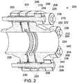
- FIG. 2 is a cross-sectional view of an exemplary flange assembly 200 that is used with SOFC system 100 (shown in FIG. 1 ).
- flange assembly 200 includes a first flange 202, a dielectric element 204, and a second flange 206.
- first flange such as first flange 202
- second flange such as second flange 206
- First flange 202 and second flange 206 correspond to standard flanges in accordance with American Society of Mechanical Engineers (ASME) flange standards but could be any flange similar to an ASME flange.
- Dielectric element 204 is fabricated or manufactured from, without limitation, any suitable dielectric material, such as any suitable ceramic material, including, for example, any composition of aluminum oxide (or "alumina").
- Dielectric element 204 is coupled between first flange 202 and second flange 206.
- dielectric element 204 is coupled between first flange 202 and second flange 206 by a plurality of fasteners or bolts, such as bolts 208, 210, 212, 214, and 216.
- Bolts 208-216 extend through a plurality of bolt holes, which are drilled, cast, 3D-printed, stamped, or made by any other suitable forming process in each of first flange 202, dielectric element 204, and second flange 206.
- Bolts 208-216 include head portions 250, 252, 254, 256, 258, and 260.
- Dielectric element 204 thus facilitates electrical insulation between first flange 202 and second flange 206. More particularly, dielectric element 204 electrically isolates or separates fluid conduits 114-120 extending from BOP subsystem 101 from fluid conduits 130-136 extending from each SOFC stack 102-106. Introduction of dielectric element 204 between flanges 202 and 206 further facilitates the use of standard ASME flanges in the construction of flange assembly 200, which reduces cost and complexity and facilitates electrical separation of system components by flange assembly 200.
- a conductive surface coating 203 is applied to dielectric element 204.
- conductive surface coating 203 is one or more of, and without limitation, painted, sprayed, baked, sputtered, filmed, foiled, meshed, and pasted onto all or a part of the surface of dielectric element 204.
- each of bolts 208, 210, 212, 214, and 216 extends through a shoulder washer, such as a shoulder washer 218, 220, 222, 224, and 226.
- Each shoulder washer 218-226 partially or completely extends about each bolt 208-216.
- each shoulder washer 218-226 partially or completely covers or surrounds each bolt 208-216.
- each shoulder washer 218-226 is fabricated or manufactured from, without limitation, a dielectric material.
- each shoulder washer 218-226 is fabricated or manufactured from, without limitation, any suitable dielectric material, such as any suitable ceramic material, including, for example, any composition of aluminum oxide.
- a washer is inserted between a bolt and a shoulder washer.
- a washer 234 is inserted between bolt 208 and shoulder washer 218.
- a washer 236 is inserted between bolt 210 and shoulder washer 220, a washer 238 is inserted between bolt 212 and shoulder washer 222, a washer 240 is inserted between bolt 214 and shoulder washer 224, and a washer 242 is inserted between bolt 216 and shoulder washer 226.
- Washers 234-242 comprise any suitable type of washer, such as, for example, and without limitation, metal or ceramic washers.
- an elastic insulation sheet such as a sheet of mica, is inserted between any of a washer 234-242 and respective shoulder washer 218-226. The application of such an insulation sheet minimizes uneven stress applied to ceramic shoulder washers 218-226, which may otherwise cause ceramic chip-off.
- each shoulder washer 218, 220, 222, 224, and 226 includes a conductive surface coating 219, 221, 223, 225, and 227, respectively, which is one or more of, and without limitation, painted, sprayed, baked, sputtered, filmed, foiled, meshed, and pasted onto a surface (e.g., an outer or exterior surface) of each shoulder washer 218-226.
- conductive coating 219-227 is applied to part of various surfaces of shoulder washers 218-226 (as described below with reference to FIG. 6 ).
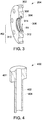
- FIG. 3 is a cross-sectional view of an exemplary dielectric element 204 of flange assembly 200 (shown in FIG. 2 ).
- dielectric element 204 includes an outer cylindrical surface 302 and an inner cylindrical surface 304.
- Inner cylindrical surface 304 defines a cylindrical region 306 through which an air or fuel gas is transferred.
- Outer cylindrical surface 302 has a radius R2.
- inner cylindrical surface 304 further defines a channel 308.
- Channel 308 extends radially about circumference, C, of inner cylindrical surface 304.
- inner cylindrical surface 304 includes a first radial wall 310 and a second radial wall 312. The first radial wall 310 is axially separated from the second radial wall 312 by a distance D.
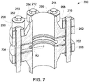
- FIG. 7 is a cross-sectional view of an alternative flange assembly 700 that is used with SOFC system 100 (shown in FIG. 1 ).
- flange assembly 700 is identical to flange assembly 200, except that flange assembly 700 includes a truncated dielectric element 702.
- truncated dielectric element 702 includes an outer cylindrical surface 704 that has a radius R3. Radius R3 is less than radius R2 of outer cylindrical surface 302 of dielectric element 204.
- truncated dielectric element 702 does not include bolt holes, because a plurality of bolts, such as bolts 208-216, extend between first flange 202 and second flange 206 without making contact with truncated dielectric element 702.
- FIG. 4 is a cross-sectional view of an exemplary shoulder washer 400 of flange assembly 200 (shown in FIG. 2 ).
- Shoulder washer 400 includes a cylindrical sleeve 402, which receives or accepts one of a plurality of bolts 208-216.
- Shoulder washer 400 further includes a shoulder portion 401 that is integrally formed with the sleeve 402 and which also receives or accepts one of bolts 208-216.
- Shoulder washer 400 further includes an exterior or outer surface 404, which is coated, as described above, with a conductive substance.
- the conductive substance is one or more of, and without limitation, painted, sprayed, baked, sputtered, filmed, foiled, meshed, and pasted onto the outer surface 404.
- FIG. 8 is a cross-sectional view of an alternative shoulder washer 800.
- Shoulder washer 800 is used with flange assembly 200 as well as flange assembly 700.
- Shoulder washer 800 thus includes a cylindrical sleeve 802, which receives or accepts one of bolts 208-216.
- Shoulder washer 800 further includes a shoulder portion 804.
- Cylindrical sleeve 802 extends through an interior cylindrical passage 806 defined by a cylindrical surface 808 within shoulder portion 804.
- cylindrical sleeve 802 does not extend to an outer collar 810 of shoulder portion 804. Rather, cylindrical sleeve 802 is seated within shoulder portion 804, such that an end 812 of cylindrical sleeve 802 rests below the level of outer collar 810.
- Shoulder portion 804 thus bears the whole load of one of bolts 208-216 when one of bolts 208-216 is inserted through shoulder washer 800 and isolates a head portion, such as one of head portions 250-258, of each bolt 208-216 from flange assembly 200 or 700.
- Such a construction provides a more robust shoulder washer 800 and allows for improved assembly tolerances.
- shoulder portion 804 and cylindrical sleeve 802 are separate pieces that are coupled together.
- shoulder portion and cylindrical sleeve 802 are integrally formed.
- Shoulder washer 800 is coated, fully or partially, like shoulder washer 400, with a conductive substance.
- FIG. 6 is a cross-sectional view of flange assembly 200.
- a first conductive surface coating 602 is applied to shoulder washer 400 at a first surface location 604.
- a second conductive surface coating 606 is applied to shoulder washer 400 at a second surface location 608.
- First conductive surface coating 602 equalizes the electrical potential between one of bolts 208-216 and first surface location 604.
- Second conductive surface coating 606 equalizes the electrical potential between flange assembly 200 and second surface location 608.
- Conductive surface coating 203 applied to dielectric element 204 acts to prevent or reduce electrical arcing or corona discharge, which may, absent conductive surface coating 203, occur between dielectric element 204 and one or both of first and second flanges 202 and 206 and/or between dielectric element 204 and other portions of flange assembly 200.
- locations 228, 230, and 232 within flange assembly 200 in which electrical arcing and/or corona discharge may occur are shown. Such locations may include small gaps between flange assembly 200 components, which may encourage the concentration of electrical charge.
- the various conductive surface coatings described herein function to more evenly distribute floating electrical charges over the surfaces of various flange assembly components, such as dielectric element 204 and shoulder washers 218-226, thereby reducing the concentration of electrical potential at corners and edges within flange assembly 200 (and consequently, the development of electrical arc and corona discharge potential in those locations).
- FIG. 5 is a cross-sectional view of flange assembly 200 in which a gas flow path is illustrated. Accordingly, during operation, a gas 501 (e.g., a gaseous air or fuel or air/fuel mixture) flows into flange assembly 200 from a first fluid conduit 502 (which is, e.g., coupled, at a distal end thereof, to BOP subsystem 101).
- a gas 501 e.g., a gaseous air or fuel or air/fuel mixture
- first fluid conduit 502 which is, e.g., coupled, at a distal end thereof, to BOP subsystem 101.
- conductive or non-conductive particles or contaminants such as coke, rust, sulfur, nickel, and metal shavings trapped or flowing within gas 501 impinge upon and collect within channel 308. More particularly, particles impinge upon second radial wall 312 of dielectric element 204, such that particles accumulate, if at all, on second radial wall 312, leaving first radial wall 310 free, or substantially free, of particle accumulation. Channel 308 thus inhibits the development of coke, and other particle, formation uniformly or evenly over cylindrical inner surface 304 of dielectric element 204.
- channel 308 induces a gap, break, or interruption in the formation of an otherwise continuous (or substantially continuous) coke layer between first flange 202 and second flange 206.
- gas 501 continues past channel 308 to exit flange assembly 200 at second fluid conduit 504, which delivers gas 501 flowing therein to one of SOFC stacks 102-106.
- Dielectric element 204 thus electrically isolates, or separates, first flange 202 from second flange 206.
- Channel 308 further acts to maintain the electrical separation between flanges 202 and 206, because channel 308 disrupts coke and other particle deposition such that a continuous (and conductive) layer of deposits is prevented by channel 308 from forming between first flange 202 and second flange 206.
- electrical currents are prevented (or discouraged) from creeping or arcing between first flange 202 and second flange 206.
- Embodiments of the SOFC system facilitate fuel and air transfer between a BOP subsystem and a plurality of SOFC stacks.
- a plurality of flange assemblies disposed between the BOP subsystem and each SOFC stack act to electrically insulate the plurality of SOFC stacks from the BOP subsystem.
- a channel within an interior portion of each flange assembly disrupts gas flow within each flange assembly to interrupt coke formation and to preserve electrical isolation between the BOP subsystem and each SOFC stack.
- Exemplary technical effects of the flange assembly described herein include, for example: (a) electrically insulating a BOP subsystem from a SOFC stack or from a plurality of SOFC stacks; (b) reducing or eliminating arcing and/or corona discharge between flange assembly components; and (c) disrupting coke and other particle accumulation within the flange assembly to maintain electrical separation between flange components.
- Exemplary embodiments of a SOFC system and related components are described above in detail.
- the system is not limited to the specific embodiments described herein, but rather, components of systems and/or steps of the methods may be utilized independently and separately from other components and/or steps described herein.
- the configuration of components described herein may also be used in combination with other processes, and is not limited to practice with the systems and related methods as described herein. Rather, the exemplary embodiment can be implemented and utilized in connection with many applications where compressing a fluid is desired.
Landscapes
- Engineering & Computer Science (AREA)
- Life Sciences & Earth Sciences (AREA)
- Manufacturing & Machinery (AREA)
- Sustainable Development (AREA)
- Sustainable Energy (AREA)
- Chemical & Material Sciences (AREA)
- Chemical Kinetics & Catalysis (AREA)
- Electrochemistry (AREA)
- General Chemical & Material Sciences (AREA)
- General Engineering & Computer Science (AREA)
- Mechanical Engineering (AREA)
- Fuel Cell (AREA)
Abstract
Description
- The subject matter disclosed herein relates to fuel cell systems and, more particularly, to a flange assembly for use with a solid oxide fuel cell (SOFC) system.
- Fuel cells are electrochemical energy conversion devices that have demonstrated a potential for relatively high efficiency and low pollution in power generation. Certain fuel cells, such as SOFCs, operate in large-scale power systems that provide electricity to satisfy industrial and municipal needs.
- Many known SOFC systems include a plurality of electrically interconnected SOFCs. More particularly, many known SOFC systems include a plurality of electrically interconnected SOFC "stacks," which, in turn, include a plurality of electrically interconnected SOFCs. During operation, a supply of fuel and air is delivered to each SOFC stack by way of one or more fuel and/or air pipes originating from an associated balance of plant (BOP) subsystem.
- Typically, BOP subsystems in known SOFC systems are electrically grounded, while the plurality of SOFC stacks operate at voltage (e.g., approximately 1000 volts). The plurality of known SOFC stacks further operate at a temperature in the range of approximately 600-800 degrees Celsius, while BOP subsystems operate at temperatures that are significantly lower.
- To electrically insulate SOFC systems from associated BOP subsystems, some known SOFC systems separate SOFC stacks from associated BOP subsystems using a dielectric material or insulator placed between each SOFC stack and its BOP mounting plate. Other known systems separate SOFC stacks using a dielectric material integrated with BOP pipes coupled to the SOFC stack.
- Conventional insulation mechanisms may, however, break down, fracture, or otherwise degrade after prolonged exposure to the electrical variations that occur between SOFC stacks and the BOP.
- In one aspect, a flange assembly for use with a SOFC system is provided. The flange assembly includes a first flange, a second flange, and a dielectric element coupled between the first flange and the second flange. The dielectric element includes an outer cylindrical surface and an inner cylindrical surface. The inner cylindrical surface defines a cylindrical region having a circumference. The inner cylindrical surface also defines a channel that extends radially about the circumference of the cylindrical region.
- In another aspect, a SOFC system is provided. The SOFC system includes a SOFC stack, a first fluid conduit extending from said SOFC stack, a BOP subsystem, a second fluid conduit extending from said BOP subsystem, and a flange assembly coupled between the first fluid conduit and the second fluid conduit. The flange assembly includes a first flange, a second flange, and a dielectric element coupled between the first flange and the second flange. The dielectric element includes an outer cylindrical surface and an inner cylindrical surface. The inner cylindrical surface defines a cylindrical region having a circumference. The inner cylindrical surface also defines a channel that extends radially about the circumference of the cylindrical region.
- In yet another aspect, a SOFC system is provided. The SOFC system includes a plurality of SOFC stacks, a BOP subsystem, and a plurality of flange assemblies. Each flange assembly is coupled between one of the plurality of SOFC stacks and the BOP subsystem. Each flange assembly includes a first flange, a second flange, and a dielectric element coupled between the first flange and the second flange. The dielectric element includes an outer cylindrical surface and an inner cylindrical surface. The inner cylindrical surface defines a cylindrical region having a circumference. The inner cylindrical surface also defines a channel that extends radially about the circumference of the cylindrical region.
- Various features, aspects, and advantages of the present disclosure will become better understood when the following detailed description is read with reference to the accompanying drawings in which like characters represent like parts throughout the drawings, wherein:
-
FIG. 1 is a perspective view of an exemplary SOFC system; -
FIG. 2 is a cross-sectional view of an exemplary flange assembly that may be used with the SOFC system shown inFIG. 1 ; -
FIG. 3 is a cross-sectional view of an exemplary dielectric element of the flange assembly shown inFIG. 2 ; -
FIG. 4 is a cross-sectional view of an exemplary shoulder washer of the flange assembly shown inFIG. 2 ; -
FIG. 5 is a cross-sectional view of the flange assembly shown inFIG. 2 in which a gas flow path is illustrated; -
FIG. 6 is a cross-sectional view of the flange assembly shown inFIG. 2 , in which a plurality of conductive surface coatings are applied; -
FIG. 7 is a cross-sectional view of an alternative flange assembly that is used with the SOFC system shown inFIG. 1 ; and -
FIG. 8 is a cross-sectional view of an alternative shoulder washer that is used with the flange assembly shown inFIG. 2 as well as the flange assembly shown inFIG. 7 . - Unless otherwise indicated, the drawings provided herein are meant to illustrate features of embodiments of the disclosure. These features are believed to be applicable in a wide variety of systems comprising one or more embodiments of the disclosure. As such, the drawings are not meant to include all conventional features known by those of ordinary skill in the art to be required for the practice of the embodiments disclosed herein.
- In the following specification and the claims, reference will be made to a number of terms, which shall be defined to have the following meanings.
- The singular forms "a", "an", and "the" include plural references unless the context clearly dictates otherwise.
- "Optional" or "optionally" means that the subsequently described event or circumstance may or may not occur, and that the description includes instances where the event occurs and instances where it does not.
- Approximating language, as used herein throughout the specification and claims, may be applied to modify any quantitative representation that could permissibly vary without resulting in a change in the basic function to which it is related. Accordingly, a value modified by a term or terms, such as "about" and "substantially", are not to be limited to the precise value specified. In at least some instances, the approximating language may correspond to the precision of an instrument for measuring the value. Here and throughout the specification and claims, range limitations may be combined and/or interchanged, such ranges are identified and include all the sub-ranges contained therein unless context or language indicates otherwise.
- Embodiments of the present disclosure relate to a flange assembly for use with a SOFC system. In the exemplary embodiment, the flange assembly is coupled between a BOP subsystem and a plurality of SOFC stacks. The flange assembly electrically insulates the plurality of SOFC stacks from the BOP subsystem. More particularly, the flange assembly includes a dielectric element that is coupled between two flanges. The dielectric element, which is cylindrical, has an interior trough or channel that interrupts or perturbs gas flow within the dielectric element during operation of the SOFC system to prevent the formation of a uniform or continuous layer of electrically conductive coke (or carbon) within the dielectric element. The dielectric element is thus designed to provide an electrical barrier that does not degrade, due to coking, over the course of time.
-
FIG. 1 is a perspective view of anexemplary SOFC system 100. SOFCsystem 100 includes a plurality of SOFC stacks, such as SOFC stacks 102, 104, and 106. Each SOFC stack 102-106 includes a plurality of interconnected SOFCs. SOFCs in a SOFC stack are, for example, electrically and mechanically interconnected. - In the exemplary embodiment, SOFC
system 100 further includes a BOP subsystem 101. As described in greater detail below, BOP subsystem 101 supplies fuel and air to each of SOFC stacks 102-106. To this end, a first plurality offluid conduits flange assemblies fluid conduits - Each flange assembly 122-128 therefore separates BOP subsystem 101 from SOFC stacks 102-106. Accordingly, as described in greater detail below, flange assemblies 122-128 facilitate electrical separation or insulation between BOP subsystem 101 and SOFC stacks 102-106.
-
FIG. 2 is a cross-sectional view of anexemplary flange assembly 200 that is used with SOFC system 100 (shown inFIG. 1 ). In the exemplary embodiment,flange assembly 200 includes afirst flange 202, adielectric element 204, and asecond flange 206. Briefly, and with returning reference toFIG. 1 , each of fluid conduits 114-120 is coupled at one end to a first flange, such asfirst flange 202, and each of fluid conduits 130-136 is coupled at one end to a second flange, such assecond flange 206. -
First flange 202 andsecond flange 206 correspond to standard flanges in accordance with American Society of Mechanical Engineers (ASME) flange standards but could be any flange similar to an ASME flange.Dielectric element 204 is fabricated or manufactured from, without limitation, any suitable dielectric material, such as any suitable ceramic material, including, for example, any composition of aluminum oxide (or "alumina"). -
Dielectric element 204 is coupled betweenfirst flange 202 andsecond flange 206. In particular,dielectric element 204 is coupled betweenfirst flange 202 andsecond flange 206 by a plurality of fasteners or bolts, such asbolts first flange 202,dielectric element 204, andsecond flange 206. Bolts 208-216 includehead portions -
Dielectric element 204 thus facilitates electrical insulation betweenfirst flange 202 andsecond flange 206. More particularly,dielectric element 204 electrically isolates or separates fluid conduits 114-120 extending from BOP subsystem 101 from fluid conduits 130-136 extending from each SOFC stack 102-106. Introduction ofdielectric element 204 betweenflanges flange assembly 200, which reduces cost and complexity and facilitates electrical separation of system components byflange assembly 200. - Further, in the exemplary embodiment, a
conductive surface coating 203 is applied todielectric element 204. In the exemplary embodiment,conductive surface coating 203 is one or more of, and without limitation, painted, sprayed, baked, sputtered, filmed, foiled, meshed, and pasted onto all or a part of the surface ofdielectric element 204. - In the exemplary embodiment, each of
bolts shoulder washer - In the exemplary embodiment, a washer is inserted between a bolt and a shoulder washer. For example, a
washer 234 is inserted betweenbolt 208 andshoulder washer 218. Likewise, awasher 236 is inserted betweenbolt 210 andshoulder washer 220, awasher 238 is inserted betweenbolt 212 andshoulder washer 222, awasher 240 is inserted betweenbolt 214 andshoulder washer 224, and awasher 242 is inserted betweenbolt 216 andshoulder washer 226. Washers 234-242 comprise any suitable type of washer, such as, for example, and without limitation, metal or ceramic washers. In an embodiment, an elastic insulation sheet, such as a sheet of mica, is inserted between any of a washer 234-242 and respective shoulder washer 218-226. The application of such an insulation sheet minimizes uneven stress applied to ceramic shoulder washers 218-226, which may otherwise cause ceramic chip-off. - Further, in the exemplary embodiment, each
shoulder washer FIG. 6 ). -
FIG. 3 is a cross-sectional view of an exemplarydielectric element 204 of flange assembly 200 (shown inFIG. 2 ). In the exemplary embodiment,dielectric element 204 includes an outercylindrical surface 302 and an innercylindrical surface 304. Innercylindrical surface 304 defines acylindrical region 306 through which an air or fuel gas is transferred. Outercylindrical surface 302 has a radius R2. Likewise,cylindrical region 306 has a radius R1 and a circumference C, which is defined by the formula C = 2πR1. - In the exemplary embodiment, inner
cylindrical surface 304 further defines achannel 308.Channel 308 extends radially about circumference, C, of innercylindrical surface 304. More particularly, innercylindrical surface 304 includes a firstradial wall 310 and a secondradial wall 312. The firstradial wall 310 is axially separated from the secondradial wall 312 by a distance D. -
FIG. 7 is a cross-sectional view of analternative flange assembly 700 that is used with SOFC system 100 (shown inFIG. 1 ). In some embodiments,flange assembly 700 is identical toflange assembly 200, except thatflange assembly 700 includes a truncateddielectric element 702. Specifically, truncateddielectric element 702 includes an outercylindrical surface 704 that has a radius R3. Radius R3 is less than radius R2 of outercylindrical surface 302 ofdielectric element 204. In addition, unlikedielectric element 204, truncateddielectric element 702 does not include bolt holes, because a plurality of bolts, such as bolts 208-216, extend betweenfirst flange 202 andsecond flange 206 without making contact with truncateddielectric element 702. -
FIG. 4 is a cross-sectional view of anexemplary shoulder washer 400 of flange assembly 200 (shown inFIG. 2 ).Shoulder washer 400 includes acylindrical sleeve 402, which receives or accepts one of a plurality of bolts 208-216.Shoulder washer 400 further includes ashoulder portion 401 that is integrally formed with thesleeve 402 and which also receives or accepts one of bolts 208-216.Shoulder washer 400 further includes an exterior orouter surface 404, which is coated, as described above, with a conductive substance. The conductive substance is one or more of, and without limitation, painted, sprayed, baked, sputtered, filmed, foiled, meshed, and pasted onto theouter surface 404. -
FIG. 8 is a cross-sectional view of analternative shoulder washer 800.Shoulder washer 800 is used withflange assembly 200 as well asflange assembly 700.Shoulder washer 800 thus includes acylindrical sleeve 802, which receives or accepts one of bolts 208-216.Shoulder washer 800 further includes ashoulder portion 804.Cylindrical sleeve 802 extends through an interiorcylindrical passage 806 defined by acylindrical surface 808 withinshoulder portion 804. However,cylindrical sleeve 802 does not extend to anouter collar 810 ofshoulder portion 804. Rather,cylindrical sleeve 802 is seated withinshoulder portion 804, such that anend 812 ofcylindrical sleeve 802 rests below the level ofouter collar 810.Shoulder portion 804 thus bears the whole load of one of bolts 208-216 when one of bolts 208-216 is inserted throughshoulder washer 800 and isolates a head portion, such as one of head portions 250-258, of each bolt 208-216 fromflange assembly robust shoulder washer 800 and allows for improved assembly tolerances. - Further, in an alternate embodiment,
shoulder portion 804 andcylindrical sleeve 802 are separate pieces that are coupled together. However, in the exemplary embodiment, shoulder portion andcylindrical sleeve 802 are integrally formed.Shoulder washer 800 is coated, fully or partially, likeshoulder washer 400, with a conductive substance. -
FIG. 6 is a cross-sectional view offlange assembly 200. As shown, in the exemplary embodiment, a firstconductive surface coating 602 is applied toshoulder washer 400 at afirst surface location 604. Similarly, a secondconductive surface coating 606 is applied toshoulder washer 400 at asecond surface location 608. Firstconductive surface coating 602 equalizes the electrical potential between one of bolts 208-216 andfirst surface location 604. Secondconductive surface coating 606 equalizes the electrical potential betweenflange assembly 200 andsecond surface location 608. -
Conductive surface coating 203 applied todielectric element 204 acts to prevent or reduce electrical arcing or corona discharge, which may, absentconductive surface coating 203, occur betweendielectric element 204 and one or both of first andsecond flanges dielectric element 204 and other portions offlange assembly 200. - For example, and with returning reference to
FIG. 2 ,several locations flange assembly 200 in which electrical arcing and/or corona discharge may occur are shown. Such locations may include small gaps betweenflange assembly 200 components, which may encourage the concentration of electrical charge. The various conductive surface coatings described herein function to more evenly distribute floating electrical charges over the surfaces of various flange assembly components, such asdielectric element 204 and shoulder washers 218-226, thereby reducing the concentration of electrical potential at corners and edges within flange assembly 200 (and consequently, the development of electrical arc and corona discharge potential in those locations). -
FIG. 5 is a cross-sectional view offlange assembly 200 in which a gas flow path is illustrated. Accordingly, during operation, a gas 501 (e.g., a gaseous air or fuel or air/fuel mixture) flows intoflange assembly 200 from a first fluid conduit 502 (which is, e.g., coupled, at a distal end thereof, to BOP subsystem 101). - As
gas 501 travels throughflange assembly 200, conductive or non-conductive particles or contaminants, such as coke, rust, sulfur, nickel, and metal shavings trapped or flowing withingas 501 impinge upon and collect withinchannel 308. More particularly, particles impinge upon secondradial wall 312 ofdielectric element 204, such that particles accumulate, if at all, on secondradial wall 312, leaving firstradial wall 310 free, or substantially free, of particle accumulation.Channel 308 thus inhibits the development of coke, and other particle, formation uniformly or evenly over cylindricalinner surface 304 ofdielectric element 204. Rather, although coke may, for example, develop and accumulate withindielectric element 204,channel 308 induces a gap, break, or interruption in the formation of an otherwise continuous (or substantially continuous) coke layer betweenfirst flange 202 andsecond flange 206. In the exemplary embodiment,gas 501 continuespast channel 308 to exitflange assembly 200 at secondfluid conduit 504, which deliversgas 501 flowing therein to one of SOFC stacks 102-106. -
Dielectric element 204 thus electrically isolates, or separates,first flange 202 fromsecond flange 206.Channel 308 further acts to maintain the electrical separation betweenflanges channel 308 disrupts coke and other particle deposition such that a continuous (and conductive) layer of deposits is prevented bychannel 308 from forming betweenfirst flange 202 andsecond flange 206. For example, as a result of the break in coke accumulation accomplished bychannel 308, electrical currents are prevented (or discouraged) from creeping or arcing betweenfirst flange 202 andsecond flange 206. - Embodiments of the SOFC system, as described above, facilitate fuel and air transfer between a BOP subsystem and a plurality of SOFC stacks. A plurality of flange assemblies disposed between the BOP subsystem and each SOFC stack act to electrically insulate the plurality of SOFC stacks from the BOP subsystem. Moreover, a channel within an interior portion of each flange assembly disrupts gas flow within each flange assembly to interrupt coke formation and to preserve electrical isolation between the BOP subsystem and each SOFC stack.
- Exemplary technical effects of the flange assembly described herein include, for example: (a) electrically insulating a BOP subsystem from a SOFC stack or from a plurality of SOFC stacks; (b) reducing or eliminating arcing and/or corona discharge between flange assembly components; and (c) disrupting coke and other particle accumulation within the flange assembly to maintain electrical separation between flange components.
- Exemplary embodiments of a SOFC system and related components are described above in detail. The system is not limited to the specific embodiments described herein, but rather, components of systems and/or steps of the methods may be utilized independently and separately from other components and/or steps described herein. For example, the configuration of components described herein may also be used in combination with other processes, and is not limited to practice with the systems and related methods as described herein. Rather, the exemplary embodiment can be implemented and utilized in connection with many applications where compressing a fluid is desired.
- Although specific features of various embodiments of the present disclosure may be shown in some drawings and not in others, this is for convenience only. In accordance with the principles of the present disclosure, any feature of a drawing may be referenced and/or claimed in combination with any feature of any other drawing.
- This written description uses examples to disclose the embodiments of the present disclosure, including the preferred mode, and also to enable any person skilled in the art to practice the disclosure, including making and using any devices or systems and performing any incorporated methods. The patentable scope of the embodiments described herein is defined by the claims, and may include other examples that occur to those skilled in the art. Such other examples are intended to be within the scope of the claims if they have structural elements that do not differ from the literal language of the claims, or if they include equivalent structural elements with insubstantial differences from the literal language of the claims.
- Various aspects and embodiments of the present invention are defined by the following numbered clauses:
- 1. A flange assembly for use with a solid oxide fuel cell (SOFC) system, said flange assembly comprising:
- a first flange;
- a second flange; and
- a dielectric element coupled between said first flange and said second flange, said dielectric element comprising an outer cylindrical surface and an inner cylindrical surface, said inner cylindrical surface defining a cylindrical region having a circumference, said inner cylindrical surface further defining a channel that extends radially about the circumference of the cylindrical region.
- 2. The flange assembly of
clause 1 further comprising at least one bolt and at least one dielectric shoulder washer, said at least one bolt coupling said first flange to said second flange, said at least one dielectric shoulder washer at least partially extending about said at least one bolt. - 3. The flange assembly of any preceding clause, wherein said dielectric shoulder washer comprises a conductive surface coating.
- 4. The flange assembly of any preceding clause, wherein said dielectric element comprises a conductive surface coating.
- 5. The flange assembly of any preceding clause, wherein said outer cylindrical surface comprises a conductive surface coating.
- 6. The flange assembly of any preceding clause, wherein the channel is configured to induce a flow perturbation within said cylindrical region.
- 7. The flange assembly of any preceding clause, wherein the channel is defined by a first radial wall and a second radial wall, said first radial wall axially separated from said second radial wall.
- 8. A solid oxide fuel cell (SOFC) system, the SOFC system comprising:
- a SOFC stack comprising a plurality of interconnected SOFCs;
- a first fluid conduit extending from said SOFC stack;
- a balance of plant (BOP) subsystem;
- a second fluid conduit extending from said BOP subsystem; and
- a flange assembly coupled between said first fluid conduit and said second fluid conduit, said flange assembly comprising:
- a first flange;
- a second flange; and
- a dielectric element coupled between said first flange and said second flange, said dielectric element comprising an outer cylindrical surface and an inner cylindrical surface, said inner cylindrical surface defining a cylindrical region having a circumference, said inner cylindrical surface further defining a channel that extends radially about the circumference of the cylindrical region.
- 9. The SOFC system of any preceding clause further comprising at least one bolt and at least one dielectric shoulder washer, said at least one bolt coupling said first flange to said second flange, said at least one dielectric shoulder washer at least partially extending about said at least one bolt.
- 10. The SOFC system of any preceding clause, wherein said dielectric shoulder washer comprises a conductive surface coating.
- 11. The SOFC system of any preceding clause, wherein said dielectric element comprises a conductive surface coating.
- 12. The SOFC system of any preceding clause, wherein said outer cylindrical surface comprises a conductive surface coating.
- 13. The SOFC system of any preceding clause, wherein the channel is defined by a first radial wall and a second radial wall, said first radial wall axially separated from said second radial wall.
- 14. A solid oxide fuel cell (SOFC) system, said SOFC system comprising:
- a plurality of SOFC stacks, each SOFC stack of said plurality of SOFC stacks comprising a plurality of interconnected SOFCs;
- a balance of plant (BOP) subsystem; and
- a plurality of flange assemblies, each flange assembly of said plurality of flange assemblies coupled between one of said plurality of SOFC stacks and said BOP subsystem, each flange assembly of said plurality of flange assemblies comprising:.
- a first flange;
- a second flange; and
- a dielectric element coupled between said first flange and said second flange, said dielectric element comprising an outer cylindrical surface and an inner cylindrical surface, said inner cylindrical surface defining a cylindrical region having a circumference, said inner cylindrical surface further defining a channel that extends radially about the circumference of the cylindrical region
- 15. The SOFC system of any preceding clause, wherein the channel is configured to induce a flow perturbation within said cylindrical region.
- 16. The SOFC system of any preceding clause further comprising at least one bolt and at least one dielectric shoulder washer, said at least one bolt coupling said first flange to said second flange, said at least one dielectric shoulder washer at least partially extending about said at least one bolt.
- 17. The SOFC system of any preceding clause, wherein said dielectric shoulder washer comprises a conductive surface coating.
- 18. The SOFC system of any preceding clause, wherein said outer cylindrical surface comprises a conductive surface coating.
- 19. The SOFC system of any preceding clause, wherein the channel is defined by a first radial wall and a second radial wall, said first radial wall axially separated from said second radial wall.
- 20. The SOFC system of any preceding clause, wherein the channel is configured to induce a flow perturbation within said cylindrical region.
Claims (15)
- A flange assembly (200) for use with a solid oxide fuel cell (SOFC) system (100), said flange assembly (200) comprising:a first flange (202);a second flange (206); anda dielectric element (204) coupled between said first flange (202) and said second flange (206), said dielectric element (204) comprising an outer cylindrical surface (302) and an inner cylindrical surface (304), said inner cylindrical surface (304) defining a cylindrical region (306) having a circumference, said inner cylindrical surface (304) further defining a channel (308) that extends radially about the circumference of the cylindrical region (306).
- The flange assembly (200) of claim 1 further comprising at least one bolt (208) and at least one dielectric shoulder washer (218), said at least one bolt (208) coupling said first flange (202) to said second flange (206), said at least one dielectric shoulder washer (218) at least partially extending about said at least one bolt (208).
- The flange assembly (200) of claim 2, wherein said dielectric shoulder washer (218) comprises a conductive surface coating (219).
- The flange assembly (200) of any preceding claim, wherein said dielectric element (204) comprises a conductive surface coating (203).
- The flange assembly (200) of any preceding claim, wherein said outer cylindrical surface (302) comprises a conductive surface coating (203).
- The flange assembly (100) of any preceding claim, wherein the channel (308) is configured to induce a flow perturbation within said cylindrical region (306).
- The flange assembly (200) of any preceding claim, wherein the channel (308) is defined by a first radial wall (310) and a second radial wall (312), said first radial wall (310) axially separated from said second radial wall (312).
- A solid oxide fuel cell (SOFC) system (100), the SOFC system (100) comprising:a SOFC stack (102);a first fluid conduit (130) extending from said SOFC stack (102);a balance of plant (BOP) subsystem (101);a second fluid conduit (114) extending from said BOP subsystem (101); anda flange assembly (122) coupled between said first fluid conduit (130) and said second fluid conduit (114), said flange assembly (122) comprising:a first flange (202);a second flange (206); anda dielectric element (204) coupled between said first flange (202) and said second flange (206), said dielectric element (204) comprising an outer cylindrical surface (302) and an inner cylindrical surface (304), said inner cylindrical surface (304) defining a cylindrical region (306) having a circumference, said inner cylindrical surface (304) further defining a channel (308) that extends radially about the circumference of the cylindrical region (306).
- The SOFC system (100) of claim 8 further comprising at least one bolt (208) and at least one dielectric shoulder washer (218), said at least one bolt (208) coupling said first flange (202) to said second flange (206), said at least one dielectric shoulder washer (218) at least partially extending about said at least one bolt (208).
- The SOFC system (100) of claim 9, wherein said dielectric shoulder washer (218) comprises a conductive surface coating (219).
- The SOFC system (100) of any of claims 8 to 10, wherein said dielectric element (204) comprises a conductive surface coating (203).
- The SOFC system (100) of any of claims to 11, wherein said outer cylindrical surface (302) comprises a conductive surface coating (203).
- The SOFC system (100) of any of claims 8 to 12, wherein the channel (308) is defined by a first radial wall (310) and a second radial wall (312), said first radial wall (310) axially separated from said second radial wall (312).
- A solid oxide fuel cell (SOFC) system (100), said SOFC system (100) comprising:a plurality of SOFC stacks (102, 104, 106);a balance of plant (BOP) subsystem (101); anda plurality of flange assemblies (122, 124, 126), each flange assembly (122, 124, 126) of said plurality of flange assemblies (122, 124, 126) coupled between one of said plurality of SOFC stacks (102, 104, 106) and said BOP subsystem (101), each flange assembly (122, 124, 126) of said plurality of flange assemblies (122, 124, 126) comprising:.a first flange (202);a second flange (206); anda dielectric element (204) coupled between said first flange (202) and said second flange (206), said dielectric element (204) comprising an outer cylindrical surface (302) and an inner cylindrical surface (304), said inner cylindrical surface (304) defining a cylindrical region (306) having a circumference, said inner cylindrical surface (304) further defining a channel (308) that extends radially about the circumference of the cylindrical region (306).
- The SOFC system (100) of claim 14, wherein the channel (308) is configured to induce a flow perturbation within said cylindrical region (306).
Applications Claiming Priority (1)
| Application Number | Priority Date | Filing Date | Title |
|---|---|---|---|
| US15/331,421 US10283804B2 (en) | 2016-10-21 | 2016-10-21 | Flange assembly for use with a solid oxide fuel cell system |
Publications (2)
| Publication Number | Publication Date |
|---|---|
| EP3312924A1 true EP3312924A1 (en) | 2018-04-25 |
| EP3312924B1 EP3312924B1 (en) | 2019-06-12 |
Family
ID=60019755
Family Applications (1)
| Application Number | Title | Priority Date | Filing Date |
|---|---|---|---|
| EP17194596.7A Active EP3312924B1 (en) | 2016-10-21 | 2017-10-03 | Flange assembly for use with a solid oxide fuel cell system |
Country Status (4)
| Country | Link |
|---|---|
| US (1) | US10283804B2 (en) |
| EP (1) | EP3312924B1 (en) |
| KR (1) | KR102465096B1 (en) |
| CN (1) | CN107978781B (en) |
Families Citing this family (2)
| Publication number | Priority date | Publication date | Assignee | Title |
|---|---|---|---|---|
| US10355294B2 (en) | 2017-03-28 | 2019-07-16 | General Electric Company | System and method for solid oxide fuel cells with staged fuel supply |
| CN113611904A (en) * | 2021-08-27 | 2021-11-05 | 华能国际电力股份有限公司 | An insulating sealing device and a fuel cell stack |
Citations (5)
| Publication number | Priority date | Publication date | Assignee | Title |
|---|---|---|---|---|
| US1592175A (en) * | 1924-07-10 | 1926-07-13 | U G I Contracting Company | Electric insulation for metal pipes |
| EP0930452A1 (en) * | 1998-01-16 | 1999-07-21 | Daiso Corporation | Gasket |
| JP2001317670A (en) * | 2000-05-02 | 2001-11-16 | Ishikawajima Harima Heavy Ind Co Ltd | Fuel cell piping electrical insulation fittings |
| US20050058872A1 (en) * | 2003-09-12 | 2005-03-17 | Blanchet Scott C. | Connection assembly for promoting electrical isolation |
| CN2856674Y (en) * | 2005-12-10 | 2007-01-10 | 张桂意 | Flange sealing device for oil field pipeline valve |
Family Cites Families (21)
| Publication number | Priority date | Publication date | Assignee | Title |
|---|---|---|---|---|
| US4467018A (en) | 1981-07-31 | 1984-08-21 | Electric Power Research Institute | Manifold dielectric barrier for a fuel cell electrical power generation system |
| AU2003243867B2 (en) | 2002-06-21 | 2008-09-18 | Versa Power Systems, Ltd. | Fuel cell insulating heat exchanger |
| US20040038109A1 (en) | 2002-08-22 | 2004-02-26 | Bernacki John E. | Apparatus for electrically insulating bipolar plates in fuel cell stack |
| US6964825B2 (en) | 2003-07-25 | 2005-11-15 | Fuelcell Energy, Inc. | Compliant manifold gasket |
| US7524573B2 (en) | 2004-02-23 | 2009-04-28 | Kabushiki Kaisha Toshiba | Fuel cell having inner and outer periphery seal members |
| US7276304B2 (en) | 2004-12-23 | 2007-10-02 | Fuelcell Energy, Inc. | Fuel cell system including a unit for electrical isolation of a fuel cell stack from a manifold assembly and method therefor |
| US20060188769A1 (en) | 2005-02-24 | 2006-08-24 | Gencell Corporation | Method and apparatus for dielectric isolation of fuel cells |
| CN101292374B (en) | 2005-08-17 | 2011-03-09 | Utc电力公司 | Solid-oxide fuel cell stack for portable power generation |
| CN101098015B (en) * | 2006-06-27 | 2010-05-12 | 中国电子科技集团公司第十八研究所 | Fuel cell stack import and export device |
| US8962210B2 (en) | 2008-06-06 | 2015-02-24 | Fuelcell Energy, Inc. | Modular fuel cell stack assembly including anode gas oxidizer and integrated external manifolds for use in fuel cell stack modules |
| US8968958B2 (en) * | 2008-07-08 | 2015-03-03 | Bloom Energy Corporation | Voltage lead jumper connected fuel cell columns |
| US8691470B2 (en) | 2008-11-12 | 2014-04-08 | Bloom Energy Corporation | Seal compositions, methods, and structures for planar solid oxide fuel cells |
| US8623569B2 (en) | 2008-12-09 | 2014-01-07 | Bloom Energy Corporation | Fuel cell seals |
| US8383283B2 (en) | 2009-04-15 | 2013-02-26 | Fuelcell Energy, Inc. | Fuel cell with electrical short circuit prevention means |
| US9005837B2 (en) | 2009-10-29 | 2015-04-14 | Fuelcell Energy, Inc. | Gasket for fuel cell system manifold seal |
| JP5684664B2 (en) | 2011-07-13 | 2015-03-18 | 本田技研工業株式会社 | Fuel cell stack |
| JP5806956B2 (en) | 2012-03-02 | 2015-11-10 | 本田技研工業株式会社 | Fuel cell stack |
| US8921001B2 (en) * | 2012-11-28 | 2014-12-30 | Bloom Energy Corporation | Hermetic high temperature dielectric conduit assemblies |
| US8968509B2 (en) | 2013-05-09 | 2015-03-03 | Bloom Energy Corporation | Methods and devices for printing seals for fuel cell stacks |
| US10109867B2 (en) * | 2013-06-26 | 2018-10-23 | Upstart Power, Inc. | Solid oxide fuel cell with flexible fuel rod support structure |
| US9090514B2 (en) | 2013-09-05 | 2015-07-28 | Fuelcell Energy, Inc. | High temperature expandable refractory |
-
2016
- 2016-10-21 US US15/331,421 patent/US10283804B2/en active Active
-
2017
- 2017-10-03 EP EP17194596.7A patent/EP3312924B1/en active Active
- 2017-10-19 KR KR1020170135888A patent/KR102465096B1/en active Active
- 2017-10-20 CN CN201710990785.5A patent/CN107978781B/en active Active
Patent Citations (5)
| Publication number | Priority date | Publication date | Assignee | Title |
|---|---|---|---|---|
| US1592175A (en) * | 1924-07-10 | 1926-07-13 | U G I Contracting Company | Electric insulation for metal pipes |
| EP0930452A1 (en) * | 1998-01-16 | 1999-07-21 | Daiso Corporation | Gasket |
| JP2001317670A (en) * | 2000-05-02 | 2001-11-16 | Ishikawajima Harima Heavy Ind Co Ltd | Fuel cell piping electrical insulation fittings |
| US20050058872A1 (en) * | 2003-09-12 | 2005-03-17 | Blanchet Scott C. | Connection assembly for promoting electrical isolation |
| CN2856674Y (en) * | 2005-12-10 | 2007-01-10 | 张桂意 | Flange sealing device for oil field pipeline valve |
Also Published As
| Publication number | Publication date |
|---|---|
| CN107978781B (en) | 2022-03-11 |
| US20180115011A1 (en) | 2018-04-26 |
| EP3312924B1 (en) | 2019-06-12 |
| KR20180044206A (en) | 2018-05-02 |
| KR102465096B1 (en) | 2022-11-08 |
| CN107978781A (en) | 2018-05-01 |
| US10283804B2 (en) | 2019-05-07 |
Similar Documents
| Publication | Publication Date | Title |
|---|---|---|
| US7374835B2 (en) | Fuel cell element | |
| EP3312924B1 (en) | Flange assembly for use with a solid oxide fuel cell system | |
| US8350181B2 (en) | Gas distribution ring assembly for plasma spray system | |
| US4225323A (en) | Ionization effected removal of alkali composition from a hot gas | |
| KR101895773B1 (en) | Corona igniter having improved gap control | |
| EP3098919B1 (en) | Gas-insulated electric apparatus | |
| CN110316390B (en) | Aircraft fuel tank isolator | |
| CN114607576B (en) | A hybrid wall Hall thruster | |
| US20180309152A1 (en) | Fuel battery stack | |
| EP1706891A2 (en) | Connection assembly for promoting electrical isolation | |
| US11715835B2 (en) | Interconnector plate for a fuel cell, and fuel cell system for an aircraft | |
| Wang et al. | The distributing characteristics of sediment deposited on pin-type grading electrodes in inner cooling circuit of HV converter valve | |
| EP3945613A1 (en) | Fuel cell and fuel cell system for an aircraft | |
| CN110641740B (en) | A micro-cathode arc thruster | |
| US8518163B2 (en) | Electrostatic filtering device using optimized emissive sites | |
| US20190078204A1 (en) | Tubular electrostatic device | |
| CN100522340C (en) | Plasma reactor | |
| Okubo et al. | Electric field distribution with dynamic charge activity in composite insulation systems under HVDC and DC-polarity reversal conditions | |
| EP2251088A3 (en) | Electrostatic separator and heating system | |
| US10436166B2 (en) | Method for optimising combustion in combustion devices and device for performing the method | |
| CN223956565U (en) | Ion source extraction device | |
| US20210339174A1 (en) | Electric filter | |
| US2900321A (en) | Electric arc reactor | |
| EP2322281B1 (en) | Heating assembly for biomass with an electrostatic separator | |
| WO2025231064A1 (en) | Fluid port with dielectrics |
Legal Events
| Date | Code | Title | Description |
|---|---|---|---|
| PUAI | Public reference made under article 153(3) epc to a published international application that has entered the european phase |
Free format text: ORIGINAL CODE: 0009012 |
|
| STAA | Information on the status of an ep patent application or granted ep patent |
Free format text: STATUS: THE APPLICATION HAS BEEN PUBLISHED |
|
| AK | Designated contracting states |
Kind code of ref document: A1 Designated state(s): AL AT BE BG CH CY CZ DE DK EE ES FI FR GB GR HR HU IE IS IT LI LT LU LV MC MK MT NL NO PL PT RO RS SE SI SK SM TR |
|
| AX | Request for extension of the european patent |
Extension state: BA ME |
|
| STAA | Information on the status of an ep patent application or granted ep patent |
Free format text: STATUS: REQUEST FOR EXAMINATION WAS MADE |
|
| 17P | Request for examination filed |
Effective date: 20181025 |
|
| RBV | Designated contracting states (corrected) |
Designated state(s): AL AT BE BG CH CY CZ DE DK EE ES FI FR GB GR HR HU IE IS IT LI LT LU LV MC MK MT NL NO PL PT RO RS SE SI SK SM TR |
|
| RIC1 | Information provided on ipc code assigned before grant |
Ipc: F16L 25/00 20060101ALI20181219BHEP Ipc: F16L 55/24 20060101ALI20181219BHEP Ipc: H01M 8/124 20160101ALN20181219BHEP Ipc: F16L 25/02 20060101ALI20181219BHEP Ipc: H01M 8/0662 20160101ALI20181219BHEP Ipc: H01M 8/2485 20160101AFI20181219BHEP |
|
| GRAP | Despatch of communication of intention to grant a patent |
Free format text: ORIGINAL CODE: EPIDOSNIGR1 |
|
| STAA | Information on the status of an ep patent application or granted ep patent |
Free format text: STATUS: GRANT OF PATENT IS INTENDED |
|
| INTG | Intention to grant announced |
Effective date: 20190204 |
|
| RIN1 | Information on inventor provided before grant (corrected) |
Inventor name: KRAHN, JOHN Inventor name: HICKEY, DARREN BAWDEN Inventor name: TAN, DANIEL QI Inventor name: HAO, LIWEI Inventor name: BROWN, KEITH GARRETTE Inventor name: GAVEL, KEVIN JOSEPH Inventor name: CHEN, QIN Inventor name: ZHANG, LILI |
|
| GRAS | Grant fee paid |
Free format text: ORIGINAL CODE: EPIDOSNIGR3 |
|
| GRAA | (expected) grant |
Free format text: ORIGINAL CODE: 0009210 |
|
| STAA | Information on the status of an ep patent application or granted ep patent |
Free format text: STATUS: THE PATENT HAS BEEN GRANTED |
|
| AK | Designated contracting states |
Kind code of ref document: B1 Designated state(s): AL AT BE BG CH CY CZ DE DK EE ES FI FR GB GR HR HU IE IS IT LI LT LU LV MC MK MT NL NO PL PT RO RS SE SI SK SM TR |
|
| REG | Reference to a national code |
Ref country code: GB Ref legal event code: FG4D |
|
| REG | Reference to a national code |
Ref country code: CH Ref legal event code: EP |
|
| REG | Reference to a national code |
Ref country code: AT Ref legal event code: REF Ref document number: 1143792 Country of ref document: AT Kind code of ref document: T Effective date: 20190615 |
|
| REG | Reference to a national code |
Ref country code: DE Ref legal event code: R096 Ref document number: 602017004462 Country of ref document: DE |
|
| REG | Reference to a national code |
Ref country code: IE Ref legal event code: FG4D |
|
| REG | Reference to a national code |
Ref country code: DE Ref legal event code: R081 Ref document number: 602017004462 Country of ref document: DE Owner name: CUMMINS ENTERPRISE LLC, INDIANAPOLIS, US Free format text: FORMER OWNER: GENERAL ELECTRIC CO., SCHENECTADY, N.Y., US |
|
| REG | Reference to a national code |
Ref country code: NL Ref legal event code: MP Effective date: 20190612 |
|
| REG | Reference to a national code |
Ref country code: LT Ref legal event code: MG4D |
|
| PG25 | Lapsed in a contracting state [announced via postgrant information from national office to epo] |
Ref country code: NO Free format text: LAPSE BECAUSE OF FAILURE TO SUBMIT A TRANSLATION OF THE DESCRIPTION OR TO PAY THE FEE WITHIN THE PRESCRIBED TIME-LIMIT Effective date: 20190912 Ref country code: LT Free format text: LAPSE BECAUSE OF FAILURE TO SUBMIT A TRANSLATION OF THE DESCRIPTION OR TO PAY THE FEE WITHIN THE PRESCRIBED TIME-LIMIT Effective date: 20190612 Ref country code: HR Free format text: LAPSE BECAUSE OF FAILURE TO SUBMIT A TRANSLATION OF THE DESCRIPTION OR TO PAY THE FEE WITHIN THE PRESCRIBED TIME-LIMIT Effective date: 20190612 Ref country code: SE Free format text: LAPSE BECAUSE OF FAILURE TO SUBMIT A TRANSLATION OF THE DESCRIPTION OR TO PAY THE FEE WITHIN THE PRESCRIBED TIME-LIMIT Effective date: 20190612 Ref country code: FI Free format text: LAPSE BECAUSE OF FAILURE TO SUBMIT A TRANSLATION OF THE DESCRIPTION OR TO PAY THE FEE WITHIN THE PRESCRIBED TIME-LIMIT Effective date: 20190612 Ref country code: AL Free format text: LAPSE BECAUSE OF FAILURE TO SUBMIT A TRANSLATION OF THE DESCRIPTION OR TO PAY THE FEE WITHIN THE PRESCRIBED TIME-LIMIT Effective date: 20190612 |
|
| RAP2 | Party data changed (patent owner data changed or rights of a patent transferred) |
Owner name: CUMMINS ENTERPRISE LLC |
|
| PG25 | Lapsed in a contracting state [announced via postgrant information from national office to epo] |
Ref country code: GR Free format text: LAPSE BECAUSE OF FAILURE TO SUBMIT A TRANSLATION OF THE DESCRIPTION OR TO PAY THE FEE WITHIN THE PRESCRIBED TIME-LIMIT Effective date: 20190913 Ref country code: LV Free format text: LAPSE BECAUSE OF FAILURE TO SUBMIT A TRANSLATION OF THE DESCRIPTION OR TO PAY THE FEE WITHIN THE PRESCRIBED TIME-LIMIT Effective date: 20190612 Ref country code: RS Free format text: LAPSE BECAUSE OF FAILURE TO SUBMIT A TRANSLATION OF THE DESCRIPTION OR TO PAY THE FEE WITHIN THE PRESCRIBED TIME-LIMIT Effective date: 20190612 Ref country code: BG Free format text: LAPSE BECAUSE OF FAILURE TO SUBMIT A TRANSLATION OF THE DESCRIPTION OR TO PAY THE FEE WITHIN THE PRESCRIBED TIME-LIMIT Effective date: 20190912 |
|
| REG | Reference to a national code |
Ref country code: AT Ref legal event code: MK05 Ref document number: 1143792 Country of ref document: AT Kind code of ref document: T Effective date: 20190612 |
|
| PG25 | Lapsed in a contracting state [announced via postgrant information from national office to epo] |
Ref country code: RO Free format text: LAPSE BECAUSE OF FAILURE TO SUBMIT A TRANSLATION OF THE DESCRIPTION OR TO PAY THE FEE WITHIN THE PRESCRIBED TIME-LIMIT Effective date: 20190612 Ref country code: SK Free format text: LAPSE BECAUSE OF FAILURE TO SUBMIT A TRANSLATION OF THE DESCRIPTION OR TO PAY THE FEE WITHIN THE PRESCRIBED TIME-LIMIT Effective date: 20190612 Ref country code: NL Free format text: LAPSE BECAUSE OF FAILURE TO SUBMIT A TRANSLATION OF THE DESCRIPTION OR TO PAY THE FEE WITHIN THE PRESCRIBED TIME-LIMIT Effective date: 20190612 Ref country code: CZ Free format text: LAPSE BECAUSE OF FAILURE TO SUBMIT A TRANSLATION OF THE DESCRIPTION OR TO PAY THE FEE WITHIN THE PRESCRIBED TIME-LIMIT Effective date: 20190612 Ref country code: PT Free format text: LAPSE BECAUSE OF FAILURE TO SUBMIT A TRANSLATION OF THE DESCRIPTION OR TO PAY THE FEE WITHIN THE PRESCRIBED TIME-LIMIT Effective date: 20191014 Ref country code: EE Free format text: LAPSE BECAUSE OF FAILURE TO SUBMIT A TRANSLATION OF THE DESCRIPTION OR TO PAY THE FEE WITHIN THE PRESCRIBED TIME-LIMIT Effective date: 20190612 Ref country code: AT Free format text: LAPSE BECAUSE OF FAILURE TO SUBMIT A TRANSLATION OF THE DESCRIPTION OR TO PAY THE FEE WITHIN THE PRESCRIBED TIME-LIMIT Effective date: 20190612 |
|
| PG25 | Lapsed in a contracting state [announced via postgrant information from national office to epo] |
Ref country code: SM Free format text: LAPSE BECAUSE OF FAILURE TO SUBMIT A TRANSLATION OF THE DESCRIPTION OR TO PAY THE FEE WITHIN THE PRESCRIBED TIME-LIMIT Effective date: 20190612 Ref country code: IS Free format text: LAPSE BECAUSE OF FAILURE TO SUBMIT A TRANSLATION OF THE DESCRIPTION OR TO PAY THE FEE WITHIN THE PRESCRIBED TIME-LIMIT Effective date: 20191012 Ref country code: IT Free format text: LAPSE BECAUSE OF FAILURE TO SUBMIT A TRANSLATION OF THE DESCRIPTION OR TO PAY THE FEE WITHIN THE PRESCRIBED TIME-LIMIT Effective date: 20190612 Ref country code: ES Free format text: LAPSE BECAUSE OF FAILURE TO SUBMIT A TRANSLATION OF THE DESCRIPTION OR TO PAY THE FEE WITHIN THE PRESCRIBED TIME-LIMIT Effective date: 20190612 |
|
| REG | Reference to a national code |
Ref country code: DE Ref legal event code: R097 Ref document number: 602017004462 Country of ref document: DE |
|
| PG25 | Lapsed in a contracting state [announced via postgrant information from national office to epo] |
Ref country code: TR Free format text: LAPSE BECAUSE OF FAILURE TO SUBMIT A TRANSLATION OF THE DESCRIPTION OR TO PAY THE FEE WITHIN THE PRESCRIBED TIME-LIMIT Effective date: 20190612 |
|
| PLBE | No opposition filed within time limit |
Free format text: ORIGINAL CODE: 0009261 |
|
| STAA | Information on the status of an ep patent application or granted ep patent |
Free format text: STATUS: NO OPPOSITION FILED WITHIN TIME LIMIT |
|
| PG25 | Lapsed in a contracting state [announced via postgrant information from national office to epo] |
Ref country code: PL Free format text: LAPSE BECAUSE OF FAILURE TO SUBMIT A TRANSLATION OF THE DESCRIPTION OR TO PAY THE FEE WITHIN THE PRESCRIBED TIME-LIMIT Effective date: 20190612 Ref country code: DK Free format text: LAPSE BECAUSE OF FAILURE TO SUBMIT A TRANSLATION OF THE DESCRIPTION OR TO PAY THE FEE WITHIN THE PRESCRIBED TIME-LIMIT Effective date: 20190612 |
|
| 26N | No opposition filed |
Effective date: 20200313 |
|
| PG25 | Lapsed in a contracting state [announced via postgrant information from national office to epo] |
Ref country code: MC Free format text: LAPSE BECAUSE OF FAILURE TO SUBMIT A TRANSLATION OF THE DESCRIPTION OR TO PAY THE FEE WITHIN THE PRESCRIBED TIME-LIMIT Effective date: 20190612 Ref country code: IS Free format text: LAPSE BECAUSE OF FAILURE TO SUBMIT A TRANSLATION OF THE DESCRIPTION OR TO PAY THE FEE WITHIN THE PRESCRIBED TIME-LIMIT Effective date: 20200224 Ref country code: SI Free format text: LAPSE BECAUSE OF FAILURE TO SUBMIT A TRANSLATION OF THE DESCRIPTION OR TO PAY THE FEE WITHIN THE PRESCRIBED TIME-LIMIT Effective date: 20190612 |
|
| PG2D | Information on lapse in contracting state deleted |
Ref country code: IS |
|
| PG25 | Lapsed in a contracting state [announced via postgrant information from national office to epo] |
Ref country code: LU Free format text: LAPSE BECAUSE OF NON-PAYMENT OF DUE FEES Effective date: 20191003 |
|
| REG | Reference to a national code |
Ref country code: BE Ref legal event code: MM Effective date: 20191031 |
|
| PG25 | Lapsed in a contracting state [announced via postgrant information from national office to epo] |
Ref country code: BE Free format text: LAPSE BECAUSE OF NON-PAYMENT OF DUE FEES Effective date: 20191031 |
|
| PG25 | Lapsed in a contracting state [announced via postgrant information from national office to epo] |
Ref country code: IE Free format text: LAPSE BECAUSE OF NON-PAYMENT OF DUE FEES Effective date: 20191003 |
|
| PG25 | Lapsed in a contracting state [announced via postgrant information from national office to epo] |
Ref country code: CY Free format text: LAPSE BECAUSE OF FAILURE TO SUBMIT A TRANSLATION OF THE DESCRIPTION OR TO PAY THE FEE WITHIN THE PRESCRIBED TIME-LIMIT Effective date: 20190612 |
|
| REG | Reference to a national code |
Ref country code: CH Ref legal event code: PL |
|
| PG25 | Lapsed in a contracting state [announced via postgrant information from national office to epo] |
Ref country code: CH Free format text: LAPSE BECAUSE OF FAILURE TO SUBMIT A TRANSLATION OF THE DESCRIPTION OR TO PAY THE FEE WITHIN THE PRESCRIBED TIME-LIMIT Effective date: 20201031 Ref country code: LI Free format text: LAPSE BECAUSE OF FAILURE TO SUBMIT A TRANSLATION OF THE DESCRIPTION OR TO PAY THE FEE WITHIN THE PRESCRIBED TIME-LIMIT Effective date: 20201031 |
|
| PG25 | Lapsed in a contracting state [announced via postgrant information from national office to epo] |
Ref country code: MT Free format text: LAPSE BECAUSE OF FAILURE TO SUBMIT A TRANSLATION OF THE DESCRIPTION OR TO PAY THE FEE WITHIN THE PRESCRIBED TIME-LIMIT Effective date: 20190612 Ref country code: HU Free format text: LAPSE BECAUSE OF FAILURE TO SUBMIT A TRANSLATION OF THE DESCRIPTION OR TO PAY THE FEE WITHIN THE PRESCRIBED TIME-LIMIT; INVALID AB INITIO Effective date: 20171003 |
|
| PG25 | Lapsed in a contracting state [announced via postgrant information from national office to epo] |
Ref country code: MK Free format text: LAPSE BECAUSE OF FAILURE TO SUBMIT A TRANSLATION OF THE DESCRIPTION OR TO PAY THE FEE WITHIN THE PRESCRIBED TIME-LIMIT Effective date: 20190612 |
|
| P01 | Opt-out of the competence of the unified patent court (upc) registered |
Free format text: CASE NUMBER: UPC_APP_118302/2023 Effective date: 20230510 |
|
| REG | Reference to a national code |
Ref country code: DE Ref legal event code: R081 Ref document number: 602017004462 Country of ref document: DE Owner name: GE VERNOVA INFRASTRUCTURE TECHNOLOGY LLC, US Free format text: FORMER OWNER: CUMMINS ENTERPRISE LLC, INDIANAPOLIS, IN, US Ref country code: DE Ref legal event code: R082 Ref document number: 602017004462 Country of ref document: DE Representative=s name: DENNEMEYER & ASSOCIATES RECHTSANWALTSGESELLSCH, DE |
|
| REG | Reference to a national code |
Ref country code: GB Ref legal event code: 732E Free format text: REGISTERED BETWEEN 20250724 AND 20250730 |
|
| PGFP | Annual fee paid to national office [announced via postgrant information from national office to epo] |
Ref country code: GB Payment date: 20250923 Year of fee payment: 9 |
|
| PGFP | Annual fee paid to national office [announced via postgrant information from national office to epo] |
Ref country code: FR Payment date: 20250923 Year of fee payment: 9 |
|
| PGFP | Annual fee paid to national office [announced via postgrant information from national office to epo] |
Ref country code: DE Payment date: 20250923 Year of fee payment: 9 |