EP3312849A1 - Method for manufacturing a flat conductor assembly - Google Patents
Method for manufacturing a flat conductor assembly Download PDFInfo
- Publication number
- EP3312849A1 EP3312849A1 EP17196281.4A EP17196281A EP3312849A1 EP 3312849 A1 EP3312849 A1 EP 3312849A1 EP 17196281 A EP17196281 A EP 17196281A EP 3312849 A1 EP3312849 A1 EP 3312849A1
- Authority
- EP
- European Patent Office
- Prior art keywords
- flat conductor
- conductor rail
- layer
- insulating layer
- rail
- Prior art date
- Legal status (The legal status is an assumption and is not a legal conclusion. Google has not performed a legal analysis and makes no representation as to the accuracy of the status listed.)
- Withdrawn
Links
Images


Classifications
-
- H—ELECTRICITY
- H01—ELECTRIC ELEMENTS
- H01B—CABLES; CONDUCTORS; INSULATORS; SELECTION OF MATERIALS FOR THEIR CONDUCTIVE, INSULATING OR DIELECTRIC PROPERTIES
- H01B13/00—Apparatus or processes specially adapted for manufacturing conductors or cables
- H01B13/06—Insulating conductors or cables
- H01B13/18—Applying discontinuous insulation, e.g. discs, beads
-
- B—PERFORMING OPERATIONS; TRANSPORTING
- B60—VEHICLES IN GENERAL
- B60R—VEHICLES, VEHICLE FITTINGS, OR VEHICLE PARTS, NOT OTHERWISE PROVIDED FOR
- B60R16/00—Electric or fluid circuits specially adapted for vehicles and not otherwise provided for; Arrangement of elements of electric or fluid circuits specially adapted for vehicles and not otherwise provided for
- B60R16/02—Electric or fluid circuits specially adapted for vehicles and not otherwise provided for; Arrangement of elements of electric or fluid circuits specially adapted for vehicles and not otherwise provided for electric constitutive elements
- B60R16/03—Electric or fluid circuits specially adapted for vehicles and not otherwise provided for; Arrangement of elements of electric or fluid circuits specially adapted for vehicles and not otherwise provided for electric constitutive elements for supply of electrical power to vehicle subsystems or for
-
- H—ELECTRICITY
- H01—ELECTRIC ELEMENTS
- H01B—CABLES; CONDUCTORS; INSULATORS; SELECTION OF MATERIALS FOR THEIR CONDUCTIVE, INSULATING OR DIELECTRIC PROPERTIES
- H01B7/00—Insulated conductors or cables characterised by their form
- H01B7/0009—Details relating to the conductive cores
- H01B7/0018—Strip or foil conductors
-
- H—ELECTRICITY
- H01—ELECTRIC ELEMENTS
- H01B—CABLES; CONDUCTORS; INSULATORS; SELECTION OF MATERIALS FOR THEIR CONDUCTIVE, INSULATING OR DIELECTRIC PROPERTIES
- H01B7/00—Insulated conductors or cables characterised by their form
- H01B7/08—Flat or ribbon cables
- H01B7/0823—Parallel wires, incorporated in a flat insulating profile
Definitions
- the invention relates to a method for producing a flat conductor arrangement.
- ground studs usually always follows the path of the lowest electrical resistance.
- bonding such as bonding, riveting, welding, and the like.
- This undirected mass return builds up an electromagnetic field that can negatively affect vehicle occupants and on-board electronics.
- flat conductor rails in particular made of aluminum, the installation space and the conductor weight for the electrical mass return can be greatly reduced.
- Such flat conductor rails are often laid along a floor group contour from a back room to an engine compartment of a vehicle.
- a multi-layered flat conductor structure as a central electrical supply and ground return eliminates the formation of an electromagnetic field independent of the used body materials.
- Such flat conductor arrangements in vehicles also achieve improved vehicle system stability.
- non-adhesive insulating materials are often used to insulate such aluminum flat core cores.
- These insulation materials often have relatively high internal mechanical stresses due to their processing, geometric arrangement and temperature changes, which may have a material shrinkage of over 20 mm over a length of 3,000 mm. Mechanical stresses can also arise in the transverse direction so that the insulation materials used break during temperature cycling tests or thermal shock tests. Due to relative movements between flat conductor rails and the insulating plastics used for insulation, v.a. Due to changes in temperature and length, it can lead to cutting effects and thus to insulation material fractures.
- a cohesive connection of the insulation plastic with the flat conductor rail would eliminate material shrinkage and optimal thermal shock resistance of the entire component, ie the coated with the insulating plastic flat conductor rail cause.
- this would entail a much more expensive and expensive stripping process, in order to solve an optimally adhering insulation of the flat conductor core, so the flat conductor rail again.
- milling off the insulating layer from the flat conductor core could cause chip formation.
- a complex cleaning process would be required. For example, in the case of a surface ablation of an insulation, a thermal change of the metal surface may occur, wherein, in addition, undefined degradation residues of the insulation may cause undesired interactions.
- an electrically conductive flat conductor rail is provided.
- This electrically conductive flat conductor rail serves as a flat conductor core of the flat conductor arrangement to be produced.
- At least one contacting region is predetermined on a flat conductor surface of the provided flat conductor rail.
- the at least one contacting area serves for contacting cables or also other conductors on the flat conductor rail.
- the flat conductor rail is a band-shaped rail made of an electrically conductive material.
- the dimensions of the flat conductor rail in the width direction and length direction are large in relation to the thickness, ie the height of the flat conductor rail.
- the said flat sides extend in the longitudinal and transverse direction of the flat conductor rail and have a substantially larger surface than respective side surfaces of the flat conductor rail, which extend in the longitudinal and vertical direction of the flat conductor.
- the flat sides also have a much larger surface than respective end faces of the flat conductor rail, which extend in the transverse and vertical direction of the flat conductor rail.
- a separating layer is applied to a partial region of the flat conductor surface comprising the contacting region.
- the separating layer has the property that a given insulating material in the contacting region adheres more strongly to the separating layer than to the flat conductor surface or at least prevents adhesion to the flat conductor surface due to the presence of the separating layer.
- an insulating material having insulating layer is made on the flat conductor rail, so after it has been provided with the release layer.
- the insulation layer is preferably produced in such a way that a connection, particularly preferably a cohesive connection, is formed between the insulation layer and the flat conductor surface and between the insulation layer and the separation layer.
- the at least one predetermined contact area serves to connect a contact element, such as a screw lug, a Mixiersteckzunge, a bolt, a cable lug or the like.
- a contact element such as a screw lug, a Mixiersteckzunge, a bolt, a cable lug or the like.
- an electrical conductor can also be electrically conductively connected to the flat conductor rail at the contacting region.
- the resulting connection between the insulating material and the flat conductor rail can basically be positive, non-positive or cohesive.
- a physical bond which is achieved by a microscopic or macroscopic toothing of the respective surfaces of the materials, ie between the flat conductor rail and the insulating material, or by shrinking the insulation layer on the flat conductor rail.
- the material bond is a chemical bond between the respective materials, ie between the flat conductor rail and the insulation material.
- Cohesive connections are all compounds in which the connection partners are held together by atomic or molecular forces. They are at the same time non-detachable connections, which can be separated mainly only by destruction of the connecting means.
- the solution according to the invention therefore consists in that a separating substance in the form of the separating layer is selectively applied to the flat conductor rail, in particular when self-adhesive or adhesive insulating material is used.
- a conventional and simplified stripping can subsequently be carried out.
- an optimum connection of the insulation material to the flat conductor rail and thus a long-term stable and temperature change resistant insulation layer is ensured.
- Surface regions of the flat conductor rail, which are to be exposed again for subsequent contact, are therefore provided with the separating layer, which connects in the production of the insulating layer with the insulating material.
- the release layer is applied selectively adhering to the points of the flat conductor rail to be stripped later.
- the separating layer connects to it, so that on the flat conductor surface, after a Removal of the insulation layer, a contact surface sufficient, further workable surface is available.
- the insulating layer can be removed without leaving any residue together with the separating layer from the flat conductor surface.
- a uniform and standardized semi-finished product can be produced by a regular, cyclic and recurrent release agent application, in which a stripping of the insulation layer can be carried out individually as required.
- the flat conductor rail serving as a flat conductor core can be produced, for example, in the form of an aluminum flat conductor core, that is to say of aluminum.
- aluminum material it is possible to use all customary extruded materials or rolled strips having a purity of at least 99.5% or higher. This ensures sufficient electrical conductivity with adjustable material hardness.
- Such aluminum conductor cores may, for example, have thicknesses of 0.5 to 5.0 mm, preferably 1.0 to 3.0 mm.
- the aluminum core widths range from 5 to 60 mm, preferably from 15 to 60 mm.
- thermoplastics or thermoplastic elastomers with sufficient electrical insulation properties and flexibility can be used as insulation material.
- polyolefins PP copolymers, PE, etc.
- polyamides PA 12, etc.
- PVC polyvinyl chloride
- TPE polyvinyl ethylene
- 0.15 to 3.5 mm preferably 0.3 to 1.5 mm, are sufficient as insulation layer thicknesses or wall thicknesses of the insulation layer.
- At respective narrow longitudinal sides of the flat conductor rails preferably 0.5 to 2.0 mm wall thickness can be applied.
- the layer thickness of the insulation layer may also have the task of compensating for a curvature of the flat conductor rail caused by a rolled strip cutting process transversely to the main alignment axis or a burr formation and to ensure a sufficient dielectric strength. Furthermore, an off-center position of the flat conductor rail serving as a flat conductor core during the production of the insulating layer can be intercepted with a sufficient insulation layer thickness or geometry.
- the flat conductor rail can have a wide variety of cross-sectional geometries or profile shapes and thereby have a variety of width and height ratios.
- aluminum is used as the material for the flat conductor rail, these may be rolled sheets, rolled strips, extruded profiles, kneading or casting materials or even films.
- the production of a flat conductor arrangement which at least one electrically conductive flat conductor rail and this at least partially enclosing insulating layer comprises allows.
- the flat conductor arrangements produced in this way can be used for targeted electrical supply and / or mass recirculation in vehicles with poorly or non-electrically conductive bodies, for example made of CFRP.
- an improvement of the electromagnetic compatibility in the vehicle can be realized without additional shielding.
- a conventional wiring harness assembly with flexible supply lines is possible, especially without external B + lines with body openings and sealing systems.
- the serving as an electrical supply and / or ground strap flat conductor assembly can be contacted at any point, so it is "multidrop" capable.
- flat conductor arrangements when aluminum is used as the material for the flat conductor rail, a particularly high degree of lightweight construction can be achieved in the manufactured flat conductor arrangement.
- Such flat conductor arrangements also have a reduced installation height in comparison to the conventional, round supply or neutral conductor.
- flat conductor arrangements produced in this way have a higher current carrying capacity than stranded conductors with the same cross-sectional area.
- using such flat conductor arrangements in a multilayer flat conductor structure an increased on-board network stability and elimination of electromagnetic fields can be achieved.
- a starter-generator battery rail and a vehicle interior supply rail (also terminal 30) can be decoupled from each other.
- the flat conductor arrangements produced in this way can be used both in 12 V, 48 V and high-voltage vehicle electrical systems.
- an advantageous embodiment of the invention provides that before the production of the insulating layer, the flat conductor surface is treated such that a cohesive connection between the insulating layer and the flat conductor rail is favored.
- the Flat conductor surface treated electrochemically, chemically or physically.
- the flat conductor surface is treated electrochemically, for example.
- An electrochemical treatment can be carried out, for example, by an anodic oxidation, for example by means of an anodization process.
- at a temperature in the production of the insulating layer can be promoted by a chemical reaction of the insulating material to the flat conductor surface of the flat conductor rail.
- other, chemical or physical surface treatments or a favorable combination of materials with regard to the insulation material used and the flat conductor rail material may favor a cohesive connection between the insulation material and the flat conductor rail.
- the release layer is applied in the form of a liquid or pasty release agent.
- the release agent can be particularly easily dosed and applied in the form of the release layer.
- the release agent is applied by means of at least one of the following methods: spray application, wherein an area surrounding the portion of the flat conductor surface is masked or wetted only locally limited; Pad printing; Roller application; Screen printing; Inkjet printing.
- spray application wherein an area surrounding the portion of the flat conductor surface is masked or wetted only locally limited
- Pad printing wherein an area surrounding the portion of the flat conductor surface is masked or wetted only locally limited
- Pad printing a roller application
- Screen printing Screen printing
- Inkjet printing Inkjet printing
- the separating layer is an adhesive tape.
- a liquid or pasty release agent can therefore also an adhesive tape or adhesive tape attached which also causes a localized separating effect between the insulating layer and the flat conductor surface.
- adhesive tapes or adhesive tapes as a release layer.
- the adhesive tapes or adhesive tapes used have the property that respective adhesives remain completely adhering to the adhesive tape or adhesive tape during removal and thus leave no residue on the flat conductor surface of the flat conductor rail. As a result, a particularly reliable electrical contacting can be ensured at the contacting region or the contacting regions.
- the separating layer comprises material components which are also located in the insulating material.
- a further advantageous embodiment of the invention provides that the insulating material is at least partially transparent and the separating layer has a different color than the insulating material and as the flat conductor rail.
- the arranged below the insulating layer contacting region is marked on the insulating layer.
- the contacting region arranged below the insulating layer that is to say the region provided with the separating layer
- the insulating layer is produced by the flat conductor rail provided with the separating layer is conveyed through an extrusion tool, by means of which the insulating layer is extruded on the outside of the flat conductor rail.
- the release layer is adhesively attached to the flat conductor rail before the extrusion process in such a way that it withstands the shear forces occurring during the extrusion, ie without the applied release layer being blurred during the extrusion or otherwise being removed from its original position on the flat conductor surface.
- the insulation layer is produced by inserting the provided with the separation layer flat conductor rail in an injection mold and then the insulating layer is molded on the outside of the flat conductor rail.
- injection molding it is also possible to completely cover the flat conductor rail, if required, with the insulating layer.
- Injection molding like extrusion, is particularly well-suited for large quantities to produce the insulation layer on the flat conductor rail in a cost-effective and reliable manner.
- Other alternatives for applying the insulation layer are the spray application or the coating via a dip.
- a further advantageous embodiment of the invention provides that the application of the release layer is integrated in a manufacturing process of the flat conductor rail or in a manufacturing process of the insulating layer.
- a flat conductor rail 1 is shown in a schematic perspective view in FIG Fig. 1 shown.
- the flat conductor rail may be made of aluminum, for example.
- the flat conductor rail serves as a so-called flat conductor core for electrical Supply or mass return in motor vehicles. It is still necessary that the flat conductor rail 1 is provided with an insulating layer, not shown here.
- At different points of a flat conductor surface 2 of the flat conductor rail 1 justify ists Berline 3 are given.
- These contacting areas 3 are used when using the flat conductor rail 1 as points at which, for example, cables or other electrical conductors are contacted on the flat conductor rail 1. Therefore, it is important that as far as possible only the bare metallic, electrically conductive material of the flat conductor rail 1 is present at these contacting regions 3.
- a release agent is applied to the respective contacting regions 3 to form respective separation layers 4 on the contacting regions 3.
- the separating layers 4 can also be applied somewhat larger than the actual contacting areas 3.
- These separating layers 4, including the separating agent used, have the property that a specific insulating material adheres more strongly to the separating layers 4 than to the flat conductor surface 2.
- the separating layers 4 can be applied, for example, by means of the punches 5 or a roll 11 shown schematically here. If the separating layers 4 are applied in the form of a liquid or pasty release agent, the following processes can be used, for example: a spray application, whereby the respective surrounding areas of the contacting regions 3 are preferably masked or the spray application locally limited, pad printing, roll application, screen printing or even inkjet printing , The release agent and thus also the release layers 4, can be applied sequentially, regularly, irregularly or selectively selectively on the flat conductor surface 2.
- the flat conductor rail 1 has relatively large, unspecified here flat sides on which the release layers 4 are applied.
- the flat conductor rail 1 is therefore very flat in the case shown here in contrast to its length and width. In that case it may be sufficient for the release layers 4 to be applied only to the flat relatively large flat sides.
- FIG. 2 another possible geometric embodiment of the flat conductor rail 1 is shown in a perspective view.
- respective narrow longitudinal sides 6 are slightly higher in the embodiment of the flat conductor rail 1 shown here than in the one shown in FIG Fig. 1 shown embodiment.
- the separating layers 4 are applied to the contacting regions 3 both on the flat relatively large flat sides and on the slightly smaller narrow longitudinal sides 6 in terms of area.
- the stripping of the insulation material to be applied later at the contact regions 3 is facilitated.
- the separating means is applied at least partially peripherally around the flat conductor rail 1.
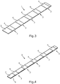
- a further possible embodiment for applying the release layers 4 at the respective contacting regions 3 is shown.
- the flat conductor rail 1 is in turn designed to be particularly flat, so that the separating layers 4 only have to be applied to the respective flat sides.
- the separating layers 4 have been band-shaped and regularly recurrently applied.
- FIG. 4 another possible embodiment for attaching the separating layers 4 is shown in a schematic perspective view.
- the flat conductor rail 1 is geometrically again as in FIG Fig. 2 is therefore somewhat thicker than the one in the Fig. 1 and 3 shown embodiments.
- the separating layers 4 have in turn been applied in strip form at regular intervals one behind the other in the longitudinal direction of the flat conductor rail 1. Since the flat conductor rail 1 in the embodiment shown here again is relatively solid, that is, formed with a certain material thickness, it makes sense again here that the separating layers 4 are circumferentially applied to the flat conductor rail 1, ie also on the narrow longitudinal sides 6.
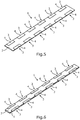
- separating layers 4 have in turn been regularly applied, wherein these have been applied in each case in lateral longitudinal areas on respective flat sides of the flat conductor rail 1.
- a further possible embodiment for the arrangement of the separating layers 4 is shown on the flat conductor rail 1.
- the flat conductor rail 1 is again as in the Fig. 2 and 4 massive and not quite as flat as in the embodiments of Fig. 1 . 3 and 5 educated.
- the separating layers 4 are in turn mounted in the longitudinal direction one behind the other in regular spacing on the flat conductor rail 1.
- the separating layers 4 comprise the respective narrow longitudinal sides 6 of the flat conductor rail 1 in the manner of a clamp.
- Fig. 7 is a schematic perspective view of a flat conductor arrangement 7 is shown, which the in Fig. 6 shown, unspecified here flat conductor rail 1 and this sheathing insulating layer 8 comprises. After like in Fig. 6 indicated the separation layers 4 have been applied to the contact areas 3, the flat conductor assembly 7 is stripped by respective sections 9 of the previously prepared insulation layer 8 are again removed from the flat conductor rail 1.
- markers 10 are produced on the insulating layer 8 at the locations under which the contact areas 3 are located, ie exactly where previously the separating layers 4 have been applied.
- the markers 10 can be lasered or printed, for example.
- the insulating layer 8 such a material is selected, which is at least partially transparent, wherein the separating layers 4 in the case then have a different color than the flat conductor rail 1 and the insulating material 8.
- the Separating layers 4 through the at least partially transparent insulation layer 8 shine through.
- the insulating layer 8 can be produced, for example, by passing the flat conductor rail 1 provided with the separating layers 4 through an extrusion tool, not shown here, by means of which the insulating layer 8 is extruded onto the flat conductor rail 1 on the outer circumference.
- the flat conductor rail 1 provided with the separating layers 4 it is also possible, for example, for the flat conductor rail 1 provided with the separating layers 4 to be inserted into an injection molding tool, likewise not shown here, by means of which insulation layer 8 is subsequently injected.
- the separating layers 4 By providing the separating layers 4, it can be ensured that the insulating layer 8 can be removed from the flat conductor rail 1 in a particularly simple manner and, in particular, without residue, at the contact regions 3.
- the respective ones Separating layers 4 are applied to the flat conductor rail 1 in such a way that they adhere to it, but adhere more strongly to this than to the flat conductor surface 2 of the flat conductor rail 1 after the production of the insulation layer 8.
- the insulating layer 8 can form a material connection with the flat conductor rail 1.
- the insulating material of the insulating layer 8 is made of thermoplastic or thermoplastic elastomers having a sufficient electrical insulating property and flexibility.
- the insulating layer 8 may be formed of polyolefins (PP copolymers, PE, etc.), polyamides (PA 12, etc.), PVC, TPE or crosslinking PE.
- the flat conductor rail 1 is made of aluminum, for example a rolled sheet, a rolled strip, an extruded profile, kneading or casting material or even of a film.
- an electrically conductive core material for the flat conductor arrangement 7 other common electrically conductive materials or alloys, for example copper or brass can be used in addition to aluminum.
Abstract
Die Erfindung betrifft ein Verfahren zum Herstellen einer Flachleiteranordnung (7), mit den Schritten: Bereitstellen einer elektrisch leitenden Flachleiterschiene (1); Vorgeben von zumindest einem Kontaktierungsbereich an der Flachleiteroberfläche (2) der Flachleiterschiene (1); Auftragen einer Trennschicht (4) an einem den Kontaktierungsbereich (3) umfassenden Teilbereich der Flachleiteroberfläche (2), wobei die Trennschicht (4) die Eigenschaft hat, stärker an einem vorgegebenen Isolationsmaterial einer Isolationsschicht (8) als an der Flachleiteroberfläche (2) anzuhaften; Herstellen der das Isolationsmaterial aufweisenden Isolationsschicht (8) an der Flachleiterschiene (1), nachdem diese mit der Trennschicht (4) versehen worden ist; Entfernen eines am Kontaktierungsbereich (3) der Flachleiterschiene (1) hergestellten Abschnitts (9) der Isolationsschicht (8) mitsamt der darunterliegenden Trennschicht (4).

Description
Die Erfindung betrifft ein Verfahren zum Herstellen einer Flachleiteranordnung.The invention relates to a method for producing a flat conductor arrangement.
Durch die vermehrte Anwendung unterschiedlicher Materialkombinationen in Fahrzeugkarosserien bis hin zur kompletten CFK-Karosserie (zum Beispiel bei Monocoques) wird zukünftig die elektrische Masserückführung bei Kraftfahrzeugen stark beeinträchtigt bzw. sogar unfunktionell. Hierdurch wäre zum Teil die Masserückführung durch den Einsatz vermehrter sogenannter Litzenleiter notwendig und eine Gewichtserhöhung des Bordnetzes bzw. des Kabelbaumes zu erwarten.Due to the increased use of different material combinations in vehicle bodies up to the complete CFRP body (for example in monocoques), the electrical mass feedback in motor vehicles will be severely impaired or even unfunctional in the future. In this way, the mass recirculation through the use of increased so-called stranded conductors would be necessary in part and an increase in weight of the electrical system or the wiring harness to be expected.
Der über sogenannte Massebolzen eingeleitete elektrische Masserückstrom folgt üblicherweise immer dem Weg des geringsten elektrischen Widerstandes. Durch die Verwendung unterschiedlicher Karosseriematerialien und Verbindungstechniken, wie zum Beispiel Kleben, Nieten, Schweißen und dergleichen, entsteht ein undefinierter bzw. ungerichteter elektrischer Masserückstrom von Verbrauchern zu einer Fahrzeugbatterie. Dieser ungerichtete Masserückstrom baut ein elektromagnetisches Feld auf, welches sich negativ auf Fahrzeuginsassen und die Bordelektronik auswirken kann.The electrical earth return current introduced via so-called ground studs usually always follows the path of the lowest electrical resistance. Through the use of different body materials and bonding techniques, such as bonding, riveting, welding, and the like, an undefined electrical ground leakage current from consumers to a vehicle battery is created. This undirected mass return builds up an electromagnetic field that can negatively affect vehicle occupants and on-board electronics.
Durch die Anwendung sogenannter Flachleiterschienen, insbesondere aus Aluminium, können der Einbauraum und das Leitergewicht für die elektrische Masserückführung stark reduziert werden. Derartige Flachleiterschienen werden häufig entlang einer Bodengruppenkontur von einem Hinterraum bis zu einem Motorraum eines Fahrzeugs verlegt. Insbesondere eine mehrlagige Flachleiterstruktur als zentrale elektrische Versorgung und Masserückführung eliminiert das Ausbilden eines elektromagnetischen Feldes unabhängig von den eingesetzten Karosseriewerkstoffen. Durch derartige Flachleiteranordnungen in Fahrzeugen wird zudem eine verbesserte Bordnetzstabilität erreicht.By using so-called flat conductor rails, in particular made of aluminum, the installation space and the conductor weight for the electrical mass return can be greatly reduced. Such flat conductor rails are often laid along a floor group contour from a back room to an engine compartment of a vehicle. In particular, a multi-layered flat conductor structure as a central electrical supply and ground return eliminates the formation of an electromagnetic field independent of the used body materials. Such flat conductor arrangements in vehicles also achieve improved vehicle system stability.
Um eine effektive gegenseitige Auslöschung von elektromagnetischen Feldern von zwei benachbarten Flachleiterschienen zu ermöglichen, ist eine möglichst nahe und flächige Positionierung der beiden Flachleiterschienen zueinander erforderlich. Im Gegensatz zu Flachleiter-Versorgungsleitungen, die hauptsächlich im Unterbodenbereich und teilweise auch im Interieurbereich ohne eine zweite, masserückführende Schiene, meist mit relativ starken PVC-Isolationsstärken von über 2,5 mm eingesetzt werden, benötigen derartige mehrschichtige Flachleiterschienen relativ geringe Isolationswandstärken.In order to enable an effective mutual extinction of electromagnetic fields of two adjacent flat conductor rails, the closest possible and planar positioning of the two flat conductor rails to each other is required. In contrast to flat conductor supply lines, which are mainly used in the underbody area and partly also in the interior without a second, masserückführende rail, usually with relatively strong PVC insulation thicknesses of about 2.5 mm, such multi-layer flat conductor rails require relatively low insulation wall thicknesses.
Um eine besonders einfache und kostengünstige Abisolierbarkeit bei Aluminiumflachleiterkernen, also bei Flachleiterschienen aus Aluminium, zu ermöglichen, werden häufig nicht anhaftende Isolationsmaterialien zum Isolieren solcher Aluminiumflachleiterkerne verwendet. Diese Isolationsmaterialien weisen durch ihre Verarbeitung, geometrische Anordnung und Temperaturwechsel jedoch häufig relativ hohe innere mechanische Spannungen auf, die einen Materialschrumpf von über 20 mm über eine Länge von 3.000 mm aufweisen können. Auch in Querrichtung können mechanische Spannungen entstehen, so dass bei Temperaturwechseltests oder Temperaturschocktests die verwendeten Isolationsmaterialien reißen. Aufgrund von Relativbewegungen zwischen Flachleiterschienen und den zur Isolierung eingesetzten Isolationskunststoffen, v.a. durch Temperaturwechsel-Längenveränderungen, kann es zu Schnitteffekten und damit zu Isolationsmaterialbrüchen kommen.In order to enable a particularly simple and cost-effective strippability in aluminum flat core cores, so in flat conductor rails made of aluminum, non-adhesive insulating materials are often used to insulate such aluminum flat core cores. These insulation materials, however, often have relatively high internal mechanical stresses due to their processing, geometric arrangement and temperature changes, which may have a material shrinkage of over 20 mm over a length of 3,000 mm. Mechanical stresses can also arise in the transverse direction so that the insulation materials used break during temperature cycling tests or thermal shock tests. Due to relative movements between flat conductor rails and the insulating plastics used for insulation, v.a. Due to changes in temperature and length, it can lead to cutting effects and thus to insulation material fractures.
Eine stoffschlüssige Verbindung des Isolationskunststoffes mit der Flachleiterschiene würde einen Materialschrumpf eliminieren und eine optimale Temperaturwechselbeständigkeit des Gesamtbauteils, also der mit dem Isolationskunststoff beschichteten Flachleiterschiene, bewirken. Jedoch würde dies ein wesentlich aufwändigeres und teureres Abisolierungsverfahren nach sich ziehen, um eine optimal anhaftende Isolation von dem Flachleiterkern, also der Flachleiterschiene, wieder zu lösen. Beispielsweise könnte ein Abfräsen der Isolationsschicht vom Flachleiterkern eine Spanbildung hervorrufen. Um einen Kurzschluss durch einen verbleibenden Metallspan zu vermeiden, wäre ein aufwändiges Reinigungsverfahren erforderlich. Bei einem flächigen Ablasern einer Isolation kann beispielsweise eine thermische Veränderung der Metalloberfläche auftreten, wobei zudem undefinierte Degradationsreste der Isolation unerwünschte Wechselwirkungen verursachen können.A cohesive connection of the insulation plastic with the flat conductor rail would eliminate material shrinkage and optimal thermal shock resistance of the entire component, ie the coated with the insulating plastic flat conductor rail cause. However, this would entail a much more expensive and expensive stripping process, in order to solve an optimally adhering insulation of the flat conductor core, so the flat conductor rail again. For example, milling off the insulating layer from the flat conductor core could cause chip formation. To avoid a short circuit through a remaining metal chip, a complex cleaning process would be required. For example, in the case of a surface ablation of an insulation, a thermal change of the metal surface may occur, wherein, in addition, undefined degradation residues of the insulation may cause undesired interactions.
Es ist daher die Aufgabe der vorliegenden Erfindung, ein Verfahren zum Herstellen einer Flachleiteranordnung, welche zumindest eine elektrisch leitende Flachleiterschiene und eine diese zumindest teilweise ummantelnde Isolationsschicht aufweist, bereitzustellen, mittels welchem gleichzeitig eine besonders stabile Verbindung zwischen der Isolationsschicht und der Flachleiterschiene und eine besonders einfache lokale Abisolierbarkeit der Isolationsschicht ermöglicht wird.It is therefore the object of the present invention to provide a method for producing a flat conductor arrangement, which has at least one electrically conductive flat conductor rail and an insulating layer which at least partially encloses the same, by means of which a particularly stable connection between the insulation layer and the flat conductor rail and a particularly simple connection local strippability of the insulation layer is made possible.
Diese Aufgabe wird durch ein Verfahren zum Herstellen einer Flachleiteranordnung mit den Merkmalen des Patentanspruchs 1 gelöst. Vorteilhafte Ausgestaltungen mit zweckmäßigen und nicht-trivialen Weiterbildungen der Erfindung sind in den abhängigen Ansprüchen angegeben.This object is achieved by a method for producing a flat conductor arrangement having the features of
Bei dem erfindungsgemäßen Verfahren zum Herstellen einer Flachleiteranordnung wird eine elektrisch leitende Flachleiterschiene bereitgestellt. Diese elektrisch leitende Flachleiterschiene dient als Flachleiterkern der herzustellenden Flachleiteranordnung. Es wird zumindest ein Kontaktierungsbereich an einer Flachleiteroberfläche der bereitgestellten Flachleiterschiene vorgegeben. Bei der Verwendung der Flachleiteranordnung, insbesondere zur elektrischen Masserückführung in Kraftfahrzeugen, dient der zumindest eine Kontaktierungsbereich zum Kontaktieren von Kabeln oder auch anderen Leitern an der Flachleiterschiene.In the method according to the invention for producing a flat conductor arrangement, an electrically conductive flat conductor rail is provided. This electrically conductive flat conductor rail serves as a flat conductor core of the flat conductor arrangement to be produced. At least one contacting region is predetermined on a flat conductor surface of the provided flat conductor rail. When using the flat conductor arrangement, in particular for electrical mass feedback in motor vehicles, the at least one contacting area serves for contacting cables or also other conductors on the flat conductor rail.
Bei der Flachleiterschiene handelt es sich um eine bandförmige Schiene aus einem stromleitenden Material. Die Abmaße der Flachleiterschiene in Breitenrichtung und Längenrichtung sind dabei groß im Verhältnis zur Dicke, also der Höhe, der Flachleiterschiene. Die besagten Flachseiten erstrecken sich in Längs- und Querrichtung der Flachleiterschiene und weisen eine wesentlich größere Oberfläche als jeweilige Seitenflächen der Flachleiterschiene auf, die sich in Längs- und Hochrichtung der Flachleiter erstrecken. Die Flachseiten weisen zudem auch eine wesentlich größere Oberfläche als jeweilige Stirnflächen der Flachleiterschiene auf, die sich in Quer- und Hochrichtung der Flachleiterschiene erstrecken.The flat conductor rail is a band-shaped rail made of an electrically conductive material. The dimensions of the flat conductor rail in the width direction and length direction are large in relation to the thickness, ie the height of the flat conductor rail. The said flat sides extend in the longitudinal and transverse direction of the flat conductor rail and have a substantially larger surface than respective side surfaces of the flat conductor rail, which extend in the longitudinal and vertical direction of the flat conductor. The flat sides also have a much larger surface than respective end faces of the flat conductor rail, which extend in the transverse and vertical direction of the flat conductor rail.
An einem den Kontaktierungsbereich umfassenden Teilbereich der Flachleiteroberfläche wird anschließend eine Trennschicht aufgetragen. Die Trennschicht hat dabei die Eigenschaft, dass ein vorgegebenes Isolationsmaterial im Kontaktierungsbereich stärker an der Trennschicht als an der Flachleiteroberfläche anhaftet oder zumindest eine Anhaftung an die Flachleiteroberfläche durch die Anwesenheit der Trennschicht unterbunden wird. Anschließend wird eine das Isolationsmaterial aufweisende Isolationsschicht an der Flachleiterschiene hergestellt, also nachdem diese mit der Trennschicht versehen worden ist. Das Herstellen der Isolationsschicht erfolgt dabei vorzugsweise derart, dass eine Verbindung, besonders bevorzugt eine stoffschlüssige Verbindung, zwischen der Isolationsschicht und der Flachleiteroberfläche sowie zwischen der Isolationsschicht und der Trennschicht ausgebildet wird. Schließlich wird ein am Kontaktierungsbereich der Flachleiterschiene hergestellter Abschnitt der Isolationsschicht mitsamt der darunterliegenden Trennschicht entfernt.Subsequently, a separating layer is applied to a partial region of the flat conductor surface comprising the contacting region. In this case, the separating layer has the property that a given insulating material in the contacting region adheres more strongly to the separating layer than to the flat conductor surface or at least prevents adhesion to the flat conductor surface due to the presence of the separating layer. Subsequently, an insulating material having insulating layer is made on the flat conductor rail, so after it has been provided with the release layer. In this case, the insulation layer is preferably produced in such a way that a connection, particularly preferably a cohesive connection, is formed between the insulation layer and the flat conductor surface and between the insulation layer and the separation layer. Finally, a section of the insulating layer produced on the contacting region of the flat conductor rail, together with the separating layer underneath, is removed.
Der zumindest eine vorgegebene Kontaktierungsbereich dient zur Anbindung eines Kontaktelements, wie beispielsweise einer Schraublasche, einer Kontaktiersteckzunge, eines Schraubbolzens, einem Kabelschuh oder dergleichen. Alternativ kann an dem Kontaktierungsbereich auch direkt ein elektrischer Leiter mit der Flachleiterschiene elektrisch leitend verbunden werden.The at least one predetermined contact area serves to connect a contact element, such as a screw lug, a Kontaktiersteckzunge, a bolt, a cable lug or the like. Alternatively, an electrical conductor can also be electrically conductively connected to the flat conductor rail at the contacting region.
Die entstehende Verbindung zwischen dem Isolationsmaterial und der Flachleiterschiene kann grundsätzlich formschlüssig, kraftschlüssig oder stoffschlüssig sein. Bei den ersten beiden Mechanismen handelt es sich um eine physikalische Bindung, welche durch eine mikroskopische oder makroskopische Verzahnung der jeweiligen Oberflächen der Werkstoffe, also zwischen der Flachleiterschiene und dem Isolationsmaterial, oder durch ein Aufschrumpfen der Isolationsschicht auf die Flachleiterschiene erzielt wird. Der Stoffschluss hingegen ist eine chemische Bindung zwischen den jeweiligen Werkstoffen, also zwischen der Flachleiterschiene und dem Isolationsmaterial. Stoffschlüssige Verbindungen werden alle Verbindungen genannt, bei denen die Verbindungspartner durch atomare oder molekulare Kräfte zusammengehalten werden. Sie sind gleichzeitig nicht lösbare Verbindungen, die sich hauptsächlich nur durch Zerstörung der Verbindungsmittel trennen lassen.The resulting connection between the insulating material and the flat conductor rail can basically be positive, non-positive or cohesive. In the first two mechanisms is a physical bond, which is achieved by a microscopic or macroscopic toothing of the respective surfaces of the materials, ie between the flat conductor rail and the insulating material, or by shrinking the insulation layer on the flat conductor rail. The material bond, however, is a chemical bond between the respective materials, ie between the flat conductor rail and the insulation material. Cohesive connections are all compounds in which the connection partners are held together by atomic or molecular forces. They are at the same time non-detachable connections, which can be separated mainly only by destruction of the connecting means.
Die erfindungsgemäße Lösung besteht also darin, dass insbesondere bei einer Verwendung von selbst- bzw. anhaftendem Isolationsmaterial selektiv auf der Flachleiterschiene ein trennender Stoff in Form der Trennschicht aufgetragen wird. In den mit der Trennschicht beaufschlagten Bereichen kann nachfolgend eine konventionelle und vereinfachte Abisolation durchgeführt werden. Hingegen wird in den anderen Bereichen der Flachleiterschiene eine optimale Verbindung des Isolationsmaterials mit der Flachleiterschiene und damit eine langzeitbeständige und temperaturwechselbeständige Isolationsschicht gewährleistet. Oberflächenbereiche der Flachleiterschiene, die für eine nachfolgende Kontaktierung wieder freigelegt werden sollen, werden also mit der Trennschicht versehen, welche sich bei der Herstellung der Isolationsschicht mit dem Isolationsmaterial verbindet. Dadurch wird eine stoffschlüssige Verbindung zwischen dem Isolationsmaterial und der Flachleiterschiene an diesen Stellen verhindert. Die Trennschicht wird dabei selektiv auf die später abzuisolierenden Stellen der Flachleiterschiene anhaftend aufgetragen. Die Trennschicht verbindet sich bei der Herstellung der Isolationsschicht mit dieser, so dass an der Flachleiteroberfläche, nach einem Entfernen der Isolationsschicht, eine für eine Kontaktierung ausreichende, weiter bearbeitbare Oberfläche zur Verfügung steht. Vorzugsweise kann die Isolationsschicht dabei rückstandslos mitsamt der Trennschicht von der Flachleiteroberfläche entfernt werden.The solution according to the invention therefore consists in that a separating substance in the form of the separating layer is selectively applied to the flat conductor rail, in particular when self-adhesive or adhesive insulating material is used. In the regions applied with the separating layer, a conventional and simplified stripping can subsequently be carried out. By contrast, in the other areas of the flat conductor rail, an optimum connection of the insulation material to the flat conductor rail and thus a long-term stable and temperature change resistant insulation layer is ensured. Surface regions of the flat conductor rail, which are to be exposed again for subsequent contact, are therefore provided with the separating layer, which connects in the production of the insulating layer with the insulating material. As a result, a cohesive connection between the insulating material and the flat conductor rail is prevented at these points. The release layer is applied selectively adhering to the points of the flat conductor rail to be stripped later. In the production of the insulating layer, the separating layer connects to it, so that on the flat conductor surface, after a Removal of the insulation layer, a contact surface sufficient, further workable surface is available. Preferably, the insulating layer can be removed without leaving any residue together with the separating layer from the flat conductor surface.
Insbesondere kann durch einen regelmäßigen, getakteten und wiederkehrenden Trennmittelauftrag ein einheitliches und standardisiertes Halbzeug hergestellt werden, bei welchem eine Abisolation der Isolationsschicht je nach Erfordernis individuell durchgeführt werden kann.In particular, a uniform and standardized semi-finished product can be produced by a regular, cyclic and recurrent release agent application, in which a stripping of the insulation layer can be carried out individually as required.
Die als Flachleiterkern dienende Flachleiterschiene kann beispielsweise in Form eines Aluminiumflachleiterkerns, also aus Aluminium, hergestellt sein. Als Aluminiummaterial können alle üblichen Strangpressmaterialien oder Walzbänder mit einer Reinheit von mindestens 99,5% oder höher eingesetzt werden. Hierdurch wird eine ausreichende elektrische Leitfähigkeit bei einstellbarer Materialhärte gewährleistet. Derartige Aluminiumleiterkerne können beispielsweise Stärken von 0,5 bis 5,0 mm, vorzugsweise von 1,0 bis 3,0 mm aufweisen. Die Aluminiumkernbreiten reichen von 5 bis 60 mm, vorzugsweise von 15 bis 60 mm.The flat conductor rail serving as a flat conductor core can be produced, for example, in the form of an aluminum flat conductor core, that is to say of aluminum. As aluminum material, it is possible to use all customary extruded materials or rolled strips having a purity of at least 99.5% or higher. This ensures sufficient electrical conductivity with adjustable material hardness. Such aluminum conductor cores may, for example, have thicknesses of 0.5 to 5.0 mm, preferably 1.0 to 3.0 mm. The aluminum core widths range from 5 to 60 mm, preferably from 15 to 60 mm.
Bei dünnen Aluminiumflachleiterkernen, ganz allgemein bei dünnen Flachleiterschienen, kann eine Beaufschlagung mit der Trennschicht auf den jeweiligen Flachseiten, also allen besonders großen Oberflächenbereichen, ausreichen. Sind hingegen die Flachleiterschienen etwas dicker, kann es auch vorgesehen sein, dass an den schmalen Längsseiten ebenfalls die Trennschicht selektiv aufgetragen wird.In the case of thin aluminum flat conductor cores, more generally in the case of thin flat conductor rails, exposure to the separating layer on the respective flat sides, ie all particularly large surface areas, may suffice. If, on the other hand, the flat conductor rails are somewhat thicker, it can also be provided that the separating layer is also selectively applied to the narrow longitudinal sides.
Als Isolationsmaterial können grundsätzlich alle Thermoplaste oder thermoplastischen Elastomere mit ausreichender elektrischer Isolationseigenschaft und Flexibilität verwendet werden. Insbesondere sind Polyolefine (PP-Copolymere, PE, etc.), Polyamide (PA 12, etc.), PVC, TPE oder vernetzendes PE einsetzbar.In principle, all thermoplastics or thermoplastic elastomers with sufficient electrical insulation properties and flexibility can be used as insulation material. In particular, polyolefins (PP copolymers, PE, etc.), polyamides (PA 12, etc.), PVC, TPE or crosslinking PE can be used.
Als Isolationsschichtstärken bzw. -wandstärken der Isolationsschicht sind je nach Kunststofftyp und Verarbeitungstechnik 0,15 bis 3,5 mm, bevorzugt 0,3 bis 1,5 mm ausreichend. An jeweiligen schmalen Längsseiten der Flachleiterschienen können bevorzugt 0,5 bis 2,0 mm Wandstärke Anwendung finden.Depending on the type of plastic and processing technology, 0.15 to 3.5 mm, preferably 0.3 to 1.5 mm, are sufficient as insulation layer thicknesses or wall thicknesses of the insulation layer. At respective narrow longitudinal sides of the flat conductor rails preferably 0.5 to 2.0 mm wall thickness can be applied.
Eigene Messungen an 60 x 1 mm Aluminiumwalzbändern mit nur 0,3 mm PP-Isolation mit Überständen an den schmalen Längsseiten der Flachleiterschiene weisen eine gemessene Durchschlagsfestigkeit von 16 KV auf. Somit können die dargestellten Flachleiteranordnungen neben dem Bereich von 12 V und 48 V auch im Hochvoltbereich angewendet werden.Own measurements on 60 x 1 mm aluminum strip with only 0.3 mm PP insulation with protrusions on the narrow longitudinal sides of the flat conductor rail have a measured dielectric strength of 16 KV. Thus, in addition to the range of 12 V and 48 V, the illustrated flat conductor arrangements can also be used in the high-voltage range.
Die Schichtstärke der Isolationsschicht kann weiterhin die Aufgabe haben, eine durch einen Walzband-Schnittprozess verursachte Wölbung der Flachleiterschiene quer zur Hauptausrichtungsachse oder eine Gratbildung auszugleichen und eine ausreichende Durchschlagsfestigkeit zu gewährleisten. Ferner kann auch eine außermittige Lage der als Flachleiterkern dienenden Flachleiterschiene während der Herstellung der Isolationsschicht mit einer ausreichenden Isolationsschichtstärkeoder -geometrie abgefangen werden.The layer thickness of the insulation layer may also have the task of compensating for a curvature of the flat conductor rail caused by a rolled strip cutting process transversely to the main alignment axis or a burr formation and to ensure a sufficient dielectric strength. Furthermore, an off-center position of the flat conductor rail serving as a flat conductor core during the production of the insulating layer can be intercepted with a sufficient insulation layer thickness or geometry.
Aufgrund des Leichtbaugedankens ist Aluminium als stromleitendes Kernmaterial für die Flachleiterschiene zu bevorzugen. Jedoch können auch weitere gängige elektrisch leitende Materialien bzw. Legierungen, wie zum Beispiel Kupfer oder Messing anstelle von Aluminium verwendet werden. Die Flachleiterschiene kann dabei unterschiedlichste Querschnittsgeometrien beziehungsweise Profilformen aufweisen und dabei verschiedenste Breiten- als auch Höhenverhältnisse aufweisen. Insbesondere wenn Aluminium als Material für die Flachleiterschiene eingesetzt wird, kann es sich dabei um Walzbleche, Walzbänder, Strangpressprofile, Knet- oder Gießmaterialien oder auch um Folien handeln.Due to the lightweight design, aluminum is to be preferred as the current-conducting core material for the flat conductor rail. However, other common electrically conductive materials or alloys, such as copper or brass instead of aluminum can be used. The flat conductor rail can have a wide variety of cross-sectional geometries or profile shapes and thereby have a variety of width and height ratios. In particular, if aluminum is used as the material for the flat conductor rail, these may be rolled sheets, rolled strips, extruded profiles, kneading or casting materials or even films.
Mittels des erfindungsgemäßen Verfahrens wird also die Herstellung einer Flachleiteranordnung, welche zumindest eine elektrisch leitende Flachleiterschiene und eine diese zumindest teilweise ummantelnde Isolationsschicht umfasst, ermöglicht. Die derart hergestellten Flachleiteranordnungen können zur gezielten elektrischen Versorgung und/oder Masserückführung in Fahrzeugen mit schlecht oder nicht elektrisch leitenden Karosserien, beispielsweise aus CFK, eingesetzt werden. Beim Einsatz derartiger Flachleiteranordnungen kann eine Verbesserung der elektromagnetischen Verträglichkeit im Fahrzeug ohne eine zusätzliche Schirmung realisiert werden. Auch ist eine konventionelle Kabelbaummontage mit flexiblen Versorgungsleitungen möglich, insbesondere ohne externe B+-Leitungen mit Karosseriedurchbrüchen und Abdichtungssystemen. Die als elektrisches Versorgungs- und/oder Masseband dienende Flachleiteranordnung kann an jeder Stelle kontaktiert werden, ist also "multidrop"-fähig. Insbesondere wenn Aluminium als Material für die Flachleiterschiene verwendet wird, kann ein besonders hoher Leichtbaugrad bei der hergestellten Flachleiteranordnung erzielt werden. Derartige Flachleiteranordnungen weisen zudem eine reduzierte Einbauhöhe im Vergleich zu den konventionellen, runden Versorgungs- oder Masselitzenleitern auf. Ferner weisen derartig hergestellte Flachleiteranordnungen eine höhere Stromtragfähigkeit als Litzenleiter mit gleicher Querschnittsfläche auf. Unter Verwendung derartiger Flachleiteranordnungen bei einer Mehrschichtflachleiterstruktur ist zudem eine erhöhte Bordnetzstabilität und Eliminierung von elektromagnetischen Feldern erzielbar. Darüber hinaus können eine Starter-Generator-Batterieschiene und eine Fahrzeuginnenraum-Versorgungsschiene (auch Klemme 30) voneinander entkoppelt werden. Die derart hergestellten Flachleiteranordnungen sind sowohl in 12 V-, 48 V-und Hochvolt-Bordnetzen einsetzbar.By means of the method according to the invention, therefore, the production of a flat conductor arrangement, which at least one electrically conductive flat conductor rail and this at least partially enclosing insulating layer comprises allows. The flat conductor arrangements produced in this way can be used for targeted electrical supply and / or mass recirculation in vehicles with poorly or non-electrically conductive bodies, for example made of CFRP. When using such flat conductor arrangements, an improvement of the electromagnetic compatibility in the vehicle can be realized without additional shielding. Also, a conventional wiring harness assembly with flexible supply lines is possible, especially without external B + lines with body openings and sealing systems. The serving as an electrical supply and / or ground strap flat conductor assembly can be contacted at any point, so it is "multidrop" capable. In particular, when aluminum is used as the material for the flat conductor rail, a particularly high degree of lightweight construction can be achieved in the manufactured flat conductor arrangement. Such flat conductor arrangements also have a reduced installation height in comparison to the conventional, round supply or neutral conductor. Furthermore, flat conductor arrangements produced in this way have a higher current carrying capacity than stranded conductors with the same cross-sectional area. In addition, using such flat conductor arrangements in a multilayer flat conductor structure, an increased on-board network stability and elimination of electromagnetic fields can be achieved. In addition, a starter-generator battery rail and a vehicle interior supply rail (also terminal 30) can be decoupled from each other. The flat conductor arrangements produced in this way can be used both in 12 V, 48 V and high-voltage vehicle electrical systems.
Die Verwendung der mittels des erfindungsgemäßen Verfahrens hergestellten Flachleiteranordnungen ist nicht nur auf den Automobilbereich beschränkt.The use of the flat conductor arrangements produced by means of the method according to the invention is not limited to the automotive sector.
Eine vorteilhafte Ausführung der Erfindung sieht vor, dass vor dem Herstellen der Isolationsschicht die Flachleiteroberfläche derart behandelt wird, dass eine stoffschlüssige Verbindung zwischen der Isolationsschicht und der Flachleiterschiene begünstigt wird. Vorzugsweise wird dafür die Flachleiteroberfläche elektrochemisch, chemisch oder physikalisch behandelt. Für eine optimale stoffschlüssige Verbindung zwischen dem Isolationsmaterial und dem Flachleiterschienenmaterial wird also vorzugsweise die Flachleiteroberfläche beispielsweise elektrochemisch behandelt. Eine elektrochemische Behandlung kann zum Beispiel durch eine anodische Oxidation, beispielsweise mittels eines Eloxalverfahrens, erfolgen. Insbesondere bei einem Temperatureintrag bei der Herstellung der Isolationsschicht kann dadurch eine chemische Reaktion des Isolationsmaterials an der Flachleiteroberfläche der Flachleiterschiene begünstigt werden. Aber auch anderweitige, chemische oder physikalische Oberflächenbehandlungen bzw. eine günstige Materialkombination im Hinblick auf den eingesetzten Isolationswerkstoff und den Flachleiterschienenwerkstoff können eine stoffschlüssige Verbindung zwischen dem Isolationsmaterial und der Flachleiterschiene begünstigen.An advantageous embodiment of the invention provides that before the production of the insulating layer, the flat conductor surface is treated such that a cohesive connection between the insulating layer and the flat conductor rail is favored. Preferably, for the Flat conductor surface treated electrochemically, chemically or physically. For an optimal cohesive connection between the insulating material and the flat conductor rail material, therefore, preferably the flat conductor surface is treated electrochemically, for example. An electrochemical treatment can be carried out, for example, by an anodic oxidation, for example by means of an anodization process. In particular, at a temperature in the production of the insulating layer can be promoted by a chemical reaction of the insulating material to the flat conductor surface of the flat conductor rail. But also other, chemical or physical surface treatments or a favorable combination of materials with regard to the insulation material used and the flat conductor rail material may favor a cohesive connection between the insulation material and the flat conductor rail.
Gemäß einer weiteren vorteilhaften Ausführungsform der Erfindung ist es vorgesehen, dass die Trennschicht in Form eines flüssigen oder pastösen Trennmittels aufgetragen wird. In flüssiger oder pastöser Form kann das Trennmittel besonders einfach dosiert und in Form der Trennschicht aufgetragen werden.According to a further advantageous embodiment of the invention, it is provided that the release layer is applied in the form of a liquid or pasty release agent. In liquid or pasty form, the release agent can be particularly easily dosed and applied in the form of the release layer.
In weiterer vorteilhafter Ausgestaltung der Erfindung ist es vorgesehen, dass das Trennmittel mittels zumindest einem der folgenden Verfahren aufgetragen wird: Sprühauftrag, wobei ein den Teilbereich umgebender Bereich der Flachleiteroberfläche maskiert oder nur lokal begrenzt benetzt wird; Tampondruck; Rollenauftrag; Siebdruck; Inkjetdruck. Je nachdem, an welchen Stellen und wie großflächig die Trennschicht aufgetragen werden soll, kann bei Verwendung eines flüssigen oder pastösen Trennmittels einer der zuvor genannten Verfahren ausgewählt werden, um ein optimales Ergebnis zu erzielen.In a further advantageous embodiment of the invention, it is provided that the release agent is applied by means of at least one of the following methods: spray application, wherein an area surrounding the portion of the flat conductor surface is masked or wetted only locally limited; Pad printing; Roller application; Screen printing; Inkjet printing. Depending on where and how large area the release layer is to be applied, one of the aforementioned methods can be selected when using a liquid or pasty release agent in order to achieve an optimum result.
Gemäß einer alternativen vorteilhaften Ausführungsform der Erfindung ist es vorgesehen, dass die Trennschicht ein Klebeband ist. Anstelle eines flüssigen oder pastösen Trennmittels kann also auch ein Klebeband oder ein Haftband angebracht werden, welches ebenfalls eine lokal begrenzte trennende Wirkung zwischen der Isolationsschicht und der Flachleiteroberfläche bewirkt. Insbesondere bei Kleinserien kann es vorteilhaft sein, Klebebänder bzw. Haftbänder als Trennschicht zu verwenden. Die eingesetzten Klebebänder oder Haftbänder haben dabei die Eigenschaft, dass jeweilige Klebestoffe beim Abziehen vollständig am Klebeband bzw. Haftband anhaften bleiben und so keine Rückstände an der Flachleiteroberfläche der Flachleiterschiene hinterlassen. Dadurch kann eine besonders zuverlässige elektrische Kontaktierung an dem Kontaktierungsbereich oder den Kontaktierungsbereichen sichergestellt werden.According to an alternative advantageous embodiment of the invention, it is provided that the separating layer is an adhesive tape. Instead of a liquid or pasty release agent can therefore also an adhesive tape or adhesive tape attached which also causes a localized separating effect between the insulating layer and the flat conductor surface. In particular, for small batches it may be advantageous to use adhesive tapes or adhesive tapes as a release layer. The adhesive tapes or adhesive tapes used have the property that respective adhesives remain completely adhering to the adhesive tape or adhesive tape during removal and thus leave no residue on the flat conductor surface of the flat conductor rail. As a result, a particularly reliable electrical contacting can be ensured at the contacting region or the contacting regions.
In weiterer vorteilhafter Ausgestaltung der Erfindung ist es vorgesehen, dass die Trennschicht Materialbestandteile umfasst, welche sich ebenfalls in dem Isolationsmaterial befinden. Dadurch wird eine Materialaffinität zwischen der Trennschicht und dem Isolationsmaterial sichergestellt, was die Verbindung, insbesondere die stoffschlüssige Verbindung, zwischen der Trennschicht und dem Isolationsmaterial begünstigt. Dies wiederum vereinfacht das rückstandslose lokale Abisolieren der Isolationsschicht.In a further advantageous embodiment of the invention, it is provided that the separating layer comprises material components which are also located in the insulating material. As a result, a material affinity between the separating layer and the insulating material is ensured, which favors the connection, in particular the cohesive connection, between the separating layer and the insulating material. This in turn simplifies the residue-free local stripping of the insulation layer.
Eine weitere vorteilhafte Ausführungsform der Erfindung sieht vor, dass das Isolationsmaterial zumindest teiltransparent ist und die Trennschicht eine andere Farbe als das Isolationsmaterial und als die Flachleiterschiene aufweist. Nach der Herstellung der Isolationsschicht kann dadurch auf besonders einfache Weise erkannt werden, wo die Trennschicht aufgetragen worden ist. Dies erleichtert das gezielte Entfernen der Isolationsschicht an den Stellen, welche beim Gebrauch der Flachleiteranordnung dann als Kontaktierungsbereich dienen sollen.A further advantageous embodiment of the invention provides that the insulating material is at least partially transparent and the separating layer has a different color than the insulating material and as the flat conductor rail. After the production of the insulating layer can be recognized in a particularly simple manner, where the release layer has been applied. This facilitates the targeted removal of the insulating layer at the locations which are then intended to serve as the contact area when using the flat conductor arrangement.
Alternativ oder zusätzlich ist es auch möglich, dass der unterhalb der Isolationsschicht angeordnete Kontaktierungsbereich auf der Isolationsschicht markiert wird. Zur Markierung des unterhalb der Isolationsschicht angeordneten Kontaktierungsbereichs, also des mit der Trennschicht versehenen Bereichs, können beispielsweise Laser oder Drucker verwendet werden. Diese Markierung sollte insbesondere mit dem jeweiligen Auftragsprozess der Trennschicht und dem dabei gegebenenfalls noch eingesetzten maskierenden Verfahren synchronisiert werden, um bei einer gezielten Entfernung der Isolationsschicht den mit der Trennschicht versehenen Bereich auch sicher treffen zu können.Alternatively or additionally, it is also possible that the arranged below the insulating layer contacting region is marked on the insulating layer. In order to mark the contacting region arranged below the insulating layer, that is to say the region provided with the separating layer, it is possible, for example, to use lasers or printers. This mark should be synchronized in particular with the respective application process of the separation layer and the thereby still possibly used masking process, in order to be able to hit the area provided with the separation layer safely even with a targeted removal of the insulation layer.
Gemäß einer weiteren vorteilhaften Ausführungsform der Erfindung ist es vorgesehen, dass die Isolationsschicht hergestellt wird, indem die mit der Trennschicht versehene Flachleiterschiene durch ein Extrusionswerkzeug hindurch befördert wird, mittels welchem die Isolationsschicht außenseitig auf die Flachleiterschiene extrudiert wird. Im Extrusionsprozess erfolgt durch Temperatur- und Druckeintrag eine physikalische Verbindung oder sogar eine chemische Reaktion zwischen dem Isolationswerkstoff und der Flachleiterschiene und zwar dort, wo die Trennschicht nicht aufgebracht worden ist. Die Trennschicht wird dabei vor dem Extrusionsprozess derart anhaftend an der Flachleiterschiene angebracht, dass sie die bei der Extrusion auftretenden Scherkräfte übersteht, also ohne dass die aufgetragene Trennschicht während der Extrusion verwischt oder anderweitig von ihrer ursprünglichen Position an der Flachleiteroberfläche entfernt wird. Durch das Extrudieren kann die Isolationsschicht besonders einfach und schnell an der Flachleiterschiene angebracht werden, insbesondere wenn die gesamte Flachleiterschiene von der Isolationsschicht ummantelt werden soll.According to a further advantageous embodiment of the invention, it is provided that the insulating layer is produced by the flat conductor rail provided with the separating layer is conveyed through an extrusion tool, by means of which the insulating layer is extruded on the outside of the flat conductor rail. In the extrusion process by temperature and pressure entry takes place a physical connection or even a chemical reaction between the insulating material and the flat conductor rail and that where the release layer has not been applied. The release layer is adhesively attached to the flat conductor rail before the extrusion process in such a way that it withstands the shear forces occurring during the extrusion, ie without the applied release layer being blurred during the extrusion or otherwise being removed from its original position on the flat conductor surface. By extruding the insulation layer can be particularly easily and quickly attached to the flat conductor rail, especially if the entire flat conductor rail to be covered by the insulation layer.
Gemäß einer alternativen vorteilhaften Ausführungsform der Erfindung ist es vorgesehen, dass die Isolationsschicht hergestellt wird, indem die mit der Trennschicht versehene Flachleiterschiene in ein Spritzgießwerkzeug eingelegt und anschließend die Isolationsschicht außenseitig auf die Flachleiterschiene angespritzt wird. Durch Spritzguss ist es ebenfalls möglich, die Flachleiterschiene, sofern denn erforderlich, vollständig mit der Isolationsschicht zu ummanteln. Spritzguss ist dabei ebenfalls wie die Extrusion besonders gut bei hohen Stückzahlen dazu geeignet, kostengünstig und prozesssicher die Isolationsschicht an der Flachleiterschiene herzustellen. Weitere Alternativen zum Auftragen der Isolationsschicht sind der Sprühauftrag oder die Beschichtung über ein Tauchbad.According to an alternative advantageous embodiment of the invention, it is provided that the insulation layer is produced by inserting the provided with the separation layer flat conductor rail in an injection mold and then the insulating layer is molded on the outside of the flat conductor rail. By injection molding, it is also possible to completely cover the flat conductor rail, if required, with the insulating layer. Injection molding, like extrusion, is particularly well-suited for large quantities to produce the insulation layer on the flat conductor rail in a cost-effective and reliable manner. Other alternatives for applying the insulation layer are the spray application or the coating via a dip.
Eine weitere vorteilhafte Ausführungsform der Erfindung sieht vor, dass das Auftragen der Trennschicht in einen Herstellprozess der Flachleiterschiene oder in einen Herstellprozess der Isolationsschicht integriert wird. Diese Integration des Auftragens der Trennschicht, entweder in den Herstellprozess der Flachleiterschiene selbst oder in den Herstellprozess der Isolationsschicht, bringt eine relativ geringe bis vernachlässigbare Kostenerhöhung mit sich, bewirkt im Nachgang aber eine wesentliche Erleichterung bei der lokalen Abisolation der Isolationsschicht.A further advantageous embodiment of the invention provides that the application of the release layer is integrated in a manufacturing process of the flat conductor rail or in a manufacturing process of the insulating layer. This integration of the application of the release layer, either in the manufacturing process of the flat conductor rail itself or in the manufacturing process of the insulation layer, brings a relatively small to negligible cost increase, but subsequently causes a substantial relief in the local stripping of the insulation layer.
Weitere Vorteile, Merkmale und Einzelheiten der Erfindung ergeben sich aus der nachfolgenden Beschreibung bevorzugter Ausführungsbeispiele sowie anhand der Zeichnungen. Die vorstehenden in der Beschreibung genannten Merkmale und Merkmalskombinationen sowie die nachfolgend in der Figurenbeschreibung genannten Merkmale und Merkmalskombinationen sind dabei nicht nur in Alleinstellung sondern auch in Kombination untereinander verwendbar, ohne den Rahmen der Erfindung zu verlassen.Further advantages, features and details of the invention will become apparent from the following description of preferred embodiments and from the drawings. The above features and feature combinations mentioned in the description as well as the features and feature combinations mentioned below in the description of the figures can be used not only alone but also in combination with one another, without departing from the scope of the invention.
Die Zeichnung zeigt in:
- Fig. 1
- eine erste Ausführungsform eines Verfahrensschritts zum Aufbringen eines Trennmittels an einer elektrisch leitenden Flachleiterschiene, wobei das Trennmittel nur an jeweils gegenüberliegenden Flachseiten der Flachleiterschiene aufgetragen wird;
- Fig. 2
- eine zweite Ausführungsform des Verfahrensschritts zum Aufbringen des Trennmittels, wobei das Trennmittel zusätzlich auch noch an jeweiligen schmalen Längsseiten der nun etwas dicker ausgeführten Flachleiterschiene aufgetragen wird;
- Fig. 3
- eine dritte Ausführungsform des Verfahrensschritts zum Aufbringen des Trennmittels, wobei das Trennmittel in Form von in Haupterstreckungsrichtung der Flachleiterschiene regelmäßig beabstandeten Querstreifen auf jeweiligen Flachseiten der Flachleiterschiene aufgetragen worden ist;
- Fig. 4
- eine vierte Ausführungsform des Verfahrensschritts zum Aufbringen des Trennmittels, wobei das Trennmittel wiederum regelmäßig in Haupterstreckungsrichtung beabstandet, allerdings in Form von abschnittsweisen Ummantelungen an der Flachleiterschiene angebracht worden ist;
- Fig. 5
- eine fünfte Ausführungsform des Verfahrensschritts zum Aufbringen des Trennmittels, wobei dieses in Haupterstreckungsrichtung regelmäßig voneinander beabstandet an jeweiligen Seitenbereichen der Flachseiten der Flachleiterschiene angebracht worden ist;
- Fig. 6
- eine sechste Ausführungsform des Verfahrensschritts zum Aufbringen des Trennmittels, wobei die Flachleiterschiene klammerartig an ihren jeweiligen schmalen Längsseiten mit dem Trennmitteln beaufschlagt worden ist; und in
- Fig. 7
- eine Perspektivansicht einer Flachleiteranordnung, welche gemäß der sechsten Ausführungsform mit dem Trennmittel beaufschlagt worden ist, wobei danach eine Isolationsschicht auf der Flachleiterschiene aufgebracht und anschließend an den mit den Trennschichten versehenen Bereichen die Isolationsschicht wieder abisoliert worden ist.
- Fig. 1
- a first embodiment of a method step for applying a release agent to an electrically conductive flat conductor rail, wherein the release agent is applied only to each opposite flat sides of the flat conductor rail;
- Fig. 2
- a second embodiment of the method step for applying the release agent, wherein the release agent is additionally also applied to respective narrow longitudinal sides of the now slightly thicker flat conductor rail;
- Fig. 3
- a third embodiment of the method step for applying the release agent, wherein the release agent in the form of in Main extension direction of the flat conductor rail regularly spaced transverse strips has been applied to respective flat sides of the flat conductor rail;
- Fig. 4
- a fourth embodiment of the method step for applying the release agent, wherein the release agent in turn regularly spaced in the main extension direction, but has been attached in the form of sectional sheaths on the flat conductor rail;
- Fig. 5
- a fifth embodiment of the method step for applying the release agent, which has been arranged in the main extension direction regularly spaced from each other at respective side regions of the flat sides of the flat conductor rail;
- Fig. 6
- a sixth embodiment of the method step for applying the release agent, wherein the flat conductor rail has been clamped on their respective narrow longitudinal sides with the release means; and in
- Fig. 7
- a perspective view of a flat conductor arrangement, which has been acted upon in accordance with the sixth embodiment, the release agent, after which an insulating layer has been applied to the flat conductor rail and then the insulation layer has been stripped again at the areas provided with the separating layers.
In den Figuren werden gleiche oder funktionsgleiche Elemente mit den gleichen Bezugszeichen versehen.In the figures, identical or functionally identical elements are provided with the same reference numerals.
Eine Flachleiterschiene 1 ist in einer schematischen Perspektivansicht in
Um eine besonders leichte Abisolierung der hier nicht dargestellten Isolationsschicht zu ermöglichen, wird an den jeweiligen Kontaktierungsbereichen 3 ein Trennmittel unter Ausbildung jeweiliger Trennschichten 4 auf den Kontaktierungsbereichen 3 aufgetragen. Die Trennschichten 4 können auch etwas großflächiger als die eigentlichen Kontaktierungsbereiche 3 aufgetragen werden. Diese Trennschichten 4, also auch das verwendete Trennmittel, haben die Eigenschaft, dass ein bestimmtes Isolationsmaterial stärker an den Trennschichten 4 als an der Flachleiteroberfläche 2 anhaftet.In order to allow a particularly easy stripping of the insulation layer, not shown here, a release agent is applied to the respective contacting
Die Trennschichten 4 können beispielsweise mittels der hier schematisch dargestellten Stempel 5 oder einer Rolle 11 aufgetragen werden. Sofern die Trennschichten 4 in Form eines flüssigen oder pastösen Trennmittels aufgetragen werden, können beispielsweise folgende Verfahren verwendet werden: ein Sprühauftrag, wobei die jeweiligen Umgebungsbereiche der Kontaktierungsbereiche 3 dabei vorzugsweise maskiert werden oder der Sprühauftrag lokal begrenzt ist, Tampondruck, Rollenauftrag, Siebdruck oder auch Inkjetdruck. Das Trennmittel und somit auch die Trennschichten 4, können sequenziell, regelmäßig, unregelmäßig oder gezielt selektiv auf der Flachleiteroberfläche 2 aufgetragen werden.The separating layers 4 can be applied, for example, by means of the
Die in
In
In
In
In
In
In
Um die gezielte Entfernung der Abschnitte 9 zu erleichtern, werden nach der Herstellung der Isolationsschicht 8 jeweilige Markierungen 10 auf der Isolationsschicht 8 an den Stellen hergestellt, unter welchen sich die Kontaktbereiche 3 befinden, also genau dort, wo zuvor die Trennschichten 4 aufgebracht worden sind. Die Markierungen 10 können beispielsweise aufgelasert oder aufgedruckt werden.In order to facilitate the targeted removal of the
Alternativ oder zusätzlich ist es auch möglich, dass für die Isolationsschicht 8 ein derartiges Material gewählt wird, welches zumindest teilweise transparent ist, wobei die Trennschichten 4 in dem Fall dann noch eine andere Farbe aufweisen als die Flachleiterschiene 1 und das Isolationsmaterial 8. Dadurch können die Trennschichten 4 durch die zumindest teilweise transparente Isolationsschicht 8 hindurchscheinen. Infolgedessen ist es auch einfach erkennbar, wo die Abschnitte 9 zum Abisolieren zu entfernen sind.Alternatively or additionally, it is also possible that for the insulating
Die Isolationsschicht 8 kann beispielsweise dadurch hergestellt werden, dass die mit den Trennschichten 4 versehene Flachleiterschiene 1 durch ein nicht hier gezeigtes Extrusionswerkzeug hindurchgeführt wird, mittels welchem die Isolationsschicht 8 außenumfangseitig auf die Flachleiterschiene 1 aufextrudiert wird. Alternativ ist es beispielsweise auch möglich, dass die mit den Trennschichten 4 versehene Flachleiterschiene 1 in ein hier ebenfalls nicht dargestelltes Spritzgießwerkzeug eingelegt wird, mittels welchem anschließend Isolationsschicht 8 angespritzt wird.The insulating
Diese Herstellungsarten gelten gleichermaßen auch für die weiteren in den
Durch das Vorsehen der Trennschichten 4 kann sichergestellt werden, dass an den Kontaktbereichen 3 die Isolationsschicht 8 besonders einfach und insbesondere rückstandsfrei von der Flachleiterschiene 1 entfernt werden kann. Die jeweiligen Trennschichten 4 werden derart auf die Flachleiterschiene 1 aufgetragen, dass sie an dieser anhaften, jedoch nach dem Herstellen der Isolationsschicht 8 stärker an dieser als an der Flachleiteroberfläche 2 der Flachleiterschiene 1 anhaften.By providing the separating layers 4, it can be ensured that the insulating
In den übrigen Bereichen der Flachleiteroberfläche 2, also dort, wo die Trennschichten 4 nicht aufgetragen sind, kann die Isolationsschicht 8 eine stoffschlüssige Verbindung mit der Flachleiterschiene 1 eingehen. Vorzugsweise besteht das Isolationsmaterial der Isolationsschicht 8 aus Thermoplasten oder thermoplastischen Elastomeren mit einer ausreichenden elektrischen Isolationseigenschaft und Flexibilität. Beispielsweise kann die Isolationsschicht 8 aus Polyolefinen (PP-Copolymere, PE, etc.), Polyamiden (PA 12, etc.), PVC, TPE oder vernetzendem PE ausgebildet sein. Insbesondere die Anwesenheit chemisch reaktiver Gruppen im Isolationsmaterial der Isolationsschicht 8, wie beispielsweise Maleinsäureanhydrid oder Polyurethangruppen, ermöglichen eine sehr gute stoffschlüssige Anbindung zur Flachleiteroberfläche.In the other regions of the
Besonders vorteilhaft ist es zudem, wenn die Flachleiterschiene 1 aus Aluminium hergestellt ist, beispielsweise aus einem Walzblech, einem Walzband, einem Strangpressprofil, aus Knet- oder Gießmaterial oder sogar aus einer Folie. Als stromleitendes Kernmaterial für die Flachleiteranordnung 7 können neben Aluminium aber auch andere gängige elektrisch leitende Materialien bzw. Legierungen, beispielsweise Kupfer oder Messing eingesetzt werden.It is also particularly advantageous if the
Neben den dargestellten Varianten der Flachleiterschiene 1 können auch weitere unterschiedlichste Querschnittsgeometrien bzw. Profilformen in der beschriebenen Weise mit den Trennschichten 4 versehen und anschließend mit der Isolationsschicht 8 überzogen werden, um anschließend im Bereich der zuvor aufgetragenen Trennschichten 4 die Abschnitte 9 der Isolationsschicht 8 zu entfernen.In addition to the illustrated variants of the
- 11
- FlachleiterschieneFlat conductor rail
- 22
- FlachleiteroberflächeFlat conductor surface
- 33
- Kontaktierungsbereichcontacting
- 44
- TrennschichtInterface
- 55
- Stempelstamp
- 66
- schmale Längsseitenarrow longitudinal side
- 77
- FlachleiteranordnungFlat conductor arrangement
- 88th
- Isolationsschichtinsulation layer
- 99
- Abschnittsection
- 1010
- Markierungmark
- 1111
- Rollerole
Claims (13)
dadurch gekennzeichnet, dass vor dem Herstellen der Isolationsschicht (8) die Flachleiteroberfläche (2) derart behandelt wird, dass eine stoffschlüssige Verbindung zwischen der Isolationsschicht (8) und der Flachleiterschiene (2) begünstigt wird.Method according to claim 1,
characterized in that before the production of the insulating layer (8), the flat conductor surface (2) is treated such that a cohesive connection between the insulating layer (8) and the flat conductor rail (2) is favored.
dadurch gekennzeichnet, dass die Flachleiteroberfläche (2) elektrochemisch, chemisch oder physikalisch behandelt wird.Method according to claim 2,
characterized in that the flat conductor surface (2) is treated electrochemically, chemically or physically.
dadurch gekennzeichnet, dass die Trennschicht (4) in Form eines flüssigen oder pastösen Trennmittels aufgetragen wird.Method according to one of the preceding claims,
characterized in that the release layer (4) is applied in the form of a liquid or pasty release agent.
dadurch gekennzeichnet, dass das Trennmittel mittels zumindest einem der folgenden Verfahren aufgetragen wird:
characterized in that the release agent is applied by at least one of the following methods:
dadurch gekennzeichnet, dass die Trennschicht (4) ein Klebeband oder Haftband ist.Method according to one of claims 1 to 3,
characterized in that the separating layer (4) is an adhesive tape or adhesive tape.
dadurch gekennzeichnet, dass die Trennschicht (4) Materialbestandteile umfasst, welche sich ebenfalls in dem Isolationsmaterial der Isolationsschicht (8) befinden.Method according to one of the preceding claims,
characterized in that the separating layer (4) comprises material components which are likewise located in the insulating material of the insulating layer (8).
dadurch gekennzeichnet, dass das Isolationsmaterial zumindest teiltransparent ist und die Trennschicht (4) eine andere Farbe als das Isolationsmaterial und als die Flachleiterschiene (2) aufweist.Method according to one of the preceding claims,
characterized in that the insulating material is at least partially transparent and the separating layer (4) has a different color than the insulating material and as the flat conductor rail (2).
dadurch gekennzeichnet, dass der unterhalb der Isolationsschicht (8) angeordnete Kontaktierungsbereich (3) auf der Isolationsschicht (8) markiert wird.Method according to one of the preceding claims,
characterized in that the below the insulating layer (8) arranged contacting region (3) on the insulating layer (8) is marked.
dadurch gekennzeichnet, dass die Isolationsschicht (8) hergestellt wird, indem die mit der Trennschicht (4) versehende Flachleiterschiene (2) durch ein Extrusionswerkzeug hindurchbefördert wird, mittels welchem die Isolationsschicht (8) außenseitig auf die Flachleiterschiene (2) extrudiert wird.Method according to one of the preceding claims,
characterized in that the insulating layer (8) is produced by the with the release layer (4) providing flat conductor rail (2) is conveyed through an extrusion die, by means of which the insulating layer (8) on the outside of the flat conductor rail (2) is extruded.
dadurch gekennzeichnet, dass die Isolationsschicht (8) hergestellt wird, indem die mit der Trennschicht (4) versehende Flachleiterschiene (2) in ein Spritzgießwerkzeug eingelegt und anschließend die Isolationsschicht (8) außenseitig auf die Flachleitschiene angespritzt wird.Method according to one of claims 1 to 9,
characterized in that the insulating layer (8) is produced by the with the release layer (4) Providing flat conductor rail (2) inserted into an injection mold and then the insulating layer (8) is molded on the outside of the flat guide rail.
dadurch gekennzeichnet, dass das Auftragen der Trennschicht (4) in einen Herstellprozess der Flachleiterschiene (1) oder in einen Herstellprozess der Isolationsschicht (8) integriert wird.Method according to one of the preceding claims,
characterized in that the application of the separating layer (4) is integrated into a production process of the flat conductor rail (1) or into a manufacturing process of the insulating layer (8).
dadurch gekennzeichnet, dass am Kontaktierungsbereich (3) der Flachleiterschiene (1) nach Entfernung des Abschnitts (9) der Isolationsschicht (8) das Anbringen eines Kontaktierungselements in Form einer Schraublasche, einer Steckzunge, eines Schraubbolzens oder eines Litzenleiters erfolgt.Method according to one of the preceding claims,
characterized in that at the contacting region (3) of the flat conductor rail (1) after removal of the portion (9) of the insulating layer (8) attaching a contacting element in the form of a Schraublasche, a tongue, a bolt or a stranded conductor takes place.
Applications Claiming Priority (1)
| Application Number | Priority Date | Filing Date | Title |
|---|---|---|---|
| DE102016119829.3A DE102016119829A1 (en) | 2016-10-18 | 2016-10-18 | METHOD FOR MANUFACTURING A FLAT LEADER ARRANGEMENT |
Publications (1)
| Publication Number | Publication Date |
|---|---|
| EP3312849A1 true EP3312849A1 (en) | 2018-04-25 |
Family
ID=60244836
Family Applications (1)
| Application Number | Title | Priority Date | Filing Date |
|---|---|---|---|
| EP17196281.4A Withdrawn EP3312849A1 (en) | 2016-10-18 | 2017-10-13 | Method for manufacturing a flat conductor assembly |
Country Status (2)
| Country | Link |
|---|---|
| EP (1) | EP3312849A1 (en) |
| DE (1) | DE102016119829A1 (en) |
Citations (4)
| Publication number | Priority date | Publication date | Assignee | Title |
|---|---|---|---|---|
| US3159555A (en) * | 1961-08-11 | 1964-12-01 | Fed Pacific Electric Co | Method of making bus bars |
| GB1086823A (en) * | 1964-02-26 | 1967-10-11 | Sumitomo Electric Industries | Improvements in or relating to insulated conductors |
| US3547718A (en) * | 1967-05-18 | 1970-12-15 | Rogers Corp | Method of making flat flexible electrical cables |
| DE102014119720A1 (en) * | 2014-12-30 | 2016-06-30 | Lisa Dräxlmaier GmbH | Insulated flat conductor and flat conductor composite |
-
2016
- 2016-10-18 DE DE102016119829.3A patent/DE102016119829A1/en active Pending
-
2017
- 2017-10-13 EP EP17196281.4A patent/EP3312849A1/en not_active Withdrawn
Patent Citations (4)
| Publication number | Priority date | Publication date | Assignee | Title |
|---|---|---|---|---|
| US3159555A (en) * | 1961-08-11 | 1964-12-01 | Fed Pacific Electric Co | Method of making bus bars |
| GB1086823A (en) * | 1964-02-26 | 1967-10-11 | Sumitomo Electric Industries | Improvements in or relating to insulated conductors |
| US3547718A (en) * | 1967-05-18 | 1970-12-15 | Rogers Corp | Method of making flat flexible electrical cables |
| DE102014119720A1 (en) * | 2014-12-30 | 2016-06-30 | Lisa Dräxlmaier GmbH | Insulated flat conductor and flat conductor composite |
Also Published As
| Publication number | Publication date |
|---|---|
| DE102016119829A1 (en) | 2018-04-19 |
Similar Documents
| Publication | Publication Date | Title |
|---|---|---|
| EP1517597B1 (en) | Method for producing a moulded component comprising an integrated conductor strip and moulded component | |
| EP0960038B1 (en) | Manufacture of a wiring loom | |
| AT510914A1 (en) | MEDICAL ELECTRODE WITH PRINTED INTRODUCTION | |
| EP1160075A2 (en) | Halogen-free composite film, process for its manufacture and its use | |
| DE112018004669T5 (en) | SOLDER-FREE FLEXIBLE CONNECTOR WITH HIGH PERFORMANCE FOR PRINTED PATHWAYS | |
| DE10207589A1 (en) | Method for producing a conductor track on a carrier component and carrier component | |
| EP1649725A1 (en) | Method for electrically insulating an electrical functional element and device with functional elements, insulated in such a way | |
| DE10014108A1 (en) | Automotive electrical connector for flexible printed circuits has flexible PCB wrapped around rigid card which is inserted along guide channel into cavity in back plane where it contacts second flexible PCB | |
| DE102014119720A1 (en) | Insulated flat conductor and flat conductor composite | |
| EP3002828B1 (en) | Sealing assembly and method for sealing the junction between electrical conductors | |
| DE2014959B2 (en) | WIRING HARNESS, IN PARTICULAR FOR USE IN AUTOMOTIVE VEHICLES, AND THE METHOD FOR MANUFACTURING IT | |
| EP3312848A1 (en) | Method for manufacturing a flat conductor assembly | |
| EP3312849A1 (en) | Method for manufacturing a flat conductor assembly | |
| DE102013016073B4 (en) | Device for signal transmission in a vehicle | |
| DE102016121948B4 (en) | Method of manufacturing a flat conductor device | |
| DE102017209519A1 (en) | Electronic component and method for its production | |
| DE102008058287B4 (en) | Electronic module with a sealing element and method for manufacturing the module | |
| DE102016114944A1 (en) | Electrical flat conductor arrangement and manufacturing method for such | |
| WO2013060511A1 (en) | Sensor arrangement with mechanical prestress | |
| EP0982805B1 (en) | Electrical connecting device | |
| DE102011077188B4 (en) | Electrical component and method of contacting an electrical component | |
| DE102016210774B3 (en) | Motor vehicle functional part with integrated antenna and method for mounting the functional part to a carrier part of the motor vehicle | |
| DE102006021560B4 (en) | Overmoulded ribbon cable with hot stamped circuit | |
| DE102013020258A1 (en) | Method and tool for producing a fiber composite component and fiber composite component | |
| DE102007014501A1 (en) | Method for producing an electrically conductive track on a plastic component |
Legal Events
| Date | Code | Title | Description |
|---|---|---|---|
| PUAI | Public reference made under article 153(3) epc to a published international application that has entered the european phase |
Free format text: ORIGINAL CODE: 0009012 |
|
| STAA | Information on the status of an ep patent application or granted ep patent |
Free format text: STATUS: THE APPLICATION HAS BEEN PUBLISHED |
|
| AK | Designated contracting states |
Kind code of ref document: A1 Designated state(s): AL AT BE BG CH CY CZ DE DK EE ES FI FR GB GR HR HU IE IS IT LI LT LU LV MC MK MT NL NO PL PT RO RS SE SI SK SM TR |
|
| AX | Request for extension of the european patent |
Extension state: BA ME |
|
| STAA | Information on the status of an ep patent application or granted ep patent |
Free format text: STATUS: REQUEST FOR EXAMINATION WAS MADE |
|
| 17P | Request for examination filed |
Effective date: 20181025 |
|
| RBV | Designated contracting states (corrected) |
Designated state(s): AL AT BE BG CH CY CZ DE DK EE ES FI FR GB GR HR HU IE IS IT LI LT LU LV MC MK MT NL NO PL PT RO RS SE SI SK SM TR |
|
| STAA | Information on the status of an ep patent application or granted ep patent |
Free format text: STATUS: REQUEST FOR EXAMINATION WAS MADE |
|
| STAA | Information on the status of an ep patent application or granted ep patent |
Free format text: STATUS: THE APPLICATION IS DEEMED TO BE WITHDRAWN |
|
| 18D | Application deemed to be withdrawn |
Effective date: 20210501 |