EP3312746A1 - System and method for simulating an operation of a gas turbine engine on an engine simulator in communication with a fadec - Google Patents
System and method for simulating an operation of a gas turbine engine on an engine simulator in communication with a fadec Download PDFInfo
- Publication number
- EP3312746A1 EP3312746A1 EP17197013.0A EP17197013A EP3312746A1 EP 3312746 A1 EP3312746 A1 EP 3312746A1 EP 17197013 A EP17197013 A EP 17197013A EP 3312746 A1 EP3312746 A1 EP 3312746A1
- Authority
- EP
- European Patent Office
- Prior art keywords
- engine
- jacobian
- fadec
- rolling
- state
- Prior art date
- Legal status (The legal status is an assumption and is not a legal conclusion. Google has not performed a legal analysis and makes no representation as to the accuracy of the status listed.)
- Withdrawn
Links
Images


Classifications
-
- G—PHYSICS
- G05—CONTROLLING; REGULATING
- G05B—CONTROL OR REGULATING SYSTEMS IN GENERAL; FUNCTIONAL ELEMENTS OF SUCH SYSTEMS; MONITORING OR TESTING ARRANGEMENTS FOR SUCH SYSTEMS OR ELEMENTS
- G05B13/00—Adaptive control systems, i.e. systems automatically adjusting themselves to have a performance which is optimum according to some preassigned criterion
- G05B13/02—Adaptive control systems, i.e. systems automatically adjusting themselves to have a performance which is optimum according to some preassigned criterion electric
- G05B13/04—Adaptive control systems, i.e. systems automatically adjusting themselves to have a performance which is optimum according to some preassigned criterion electric involving the use of models or simulators
-
- F—MECHANICAL ENGINEERING; LIGHTING; HEATING; WEAPONS; BLASTING
- F02—COMBUSTION ENGINES; HOT-GAS OR COMBUSTION-PRODUCT ENGINE PLANTS
- F02C—GAS-TURBINE PLANTS; AIR INTAKES FOR JET-PROPULSION PLANTS; CONTROLLING FUEL SUPPLY IN AIR-BREATHING JET-PROPULSION PLANTS
- F02C9/00—Controlling gas-turbine plants; Controlling fuel supply in air- breathing jet-propulsion plants
-
- G—PHYSICS
- G06—COMPUTING OR CALCULATING; COUNTING
- G06F—ELECTRIC DIGITAL DATA PROCESSING
- G06F30/00—Computer-aided design [CAD]
- G06F30/10—Geometric CAD
- G06F30/15—Vehicle, aircraft or watercraft design
-
- G—PHYSICS
- G06—COMPUTING OR CALCULATING; COUNTING
- G06F—ELECTRIC DIGITAL DATA PROCESSING
- G06F30/00—Computer-aided design [CAD]
- G06F30/20—Design optimisation, verification or simulation
-
- F—MECHANICAL ENGINEERING; LIGHTING; HEATING; WEAPONS; BLASTING
- F05—INDEXING SCHEMES RELATING TO ENGINES OR PUMPS IN VARIOUS SUBCLASSES OF CLASSES F01-F04
- F05D—INDEXING SCHEME FOR ASPECTS RELATING TO NON-POSITIVE-DISPLACEMENT MACHINES OR ENGINES, GAS-TURBINES OR JET-PROPULSION PLANTS
- F05D2270/00—Control
- F05D2270/40—Type of control system
- F05D2270/44—Type of control system active, predictive, or anticipative
-
- G—PHYSICS
- G06—COMPUTING OR CALCULATING; COUNTING
- G06F—ELECTRIC DIGITAL DATA PROCESSING
- G06F2111/00—Details relating to CAD techniques
- G06F2111/06—Multi-objective optimisation, e.g. Pareto optimisation using simulated annealing [SA], ant colony algorithms or genetic algorithms [GA]
-
- G—PHYSICS
- G06—COMPUTING OR CALCULATING; COUNTING
- G06F—ELECTRIC DIGITAL DATA PROCESSING
- G06F2111/00—Details relating to CAD techniques
- G06F2111/10—Numerical modelling
Definitions
- Exemplary embodiments pertain to the art of simulating gas turbine engine states for design and testing of engine controls.
- the simulator defines in a Jacobian matrix 110 engine parameters which, in an actual engine, define the engine state as measured by engine sensors. Minimizing the time required for the simulator to resolve the matrix for further processing is important. Innovations to date, such as reducible balance simulations, have narrowed the gap for running aero/thermo simulations in real time. There remains, however, a need for reducible balance simulations that more efficiently utilize the computing fidelity of a Jacobian matrix.
- a system for simulating an operation of a gas turbine engine having a computing system and a FADEC in electronic communication therewith, and the computer system simulating an engine state.
- the FADEC is configured to sense the simulated engine state from the computing system; determine a difference between the sensed state and a predetermined engine state; and output engine control commands intended for achieving the predetermined state; and
- the computing system is further configured to: sense the FADEC output; utilize the output in an mxm Jacobian Block, having m active balances; and perform a reduced balance simulation, wherein: fewer than m columns of the Block are analyzed, the analysis of each column defining a Rolling Jacobian Pass; and output from the Rolling Jacobian Passes is utilized in the Block, to define an updated simulated engine state.
- the number of Rolling Jacobian Passes completed in a delta time DT depends upon: the relative influence of each Rolling Jacobian Pass; and the number of Rolling Jacobian Passes the simulator is capable of completing in the delta time DT.
- the system is configured to perform a maximum of n iteration passes per delta time DT, and a number of iteration passes required for completing the full Block generation is greater than n.
- the maximum number of Rolling Jacobian Passes is r.
- the relative influence of each Rolling Jacobian Pass is determined empirically.
- the number of Rolling Jacobian Passes which can be completed in a delta time DT is determined empirically.
- the sensed simulated engine state identifies engine temperatures, pressures, and air and fuel flow rates.
- the FADEC is configured to control engine control surfaces, and air and fuel flow rates.
- the FADEC applies control laws to the engine after applying the control laws to the simulated engine.
- the FADEC is configured to change engine parameters after applying the engine parameters to the simulated engine.
- the FADEC is simulated.
- the FADEC and engine are both simulated.
- the method includes a step of simulating, in the computing system, an engine state.
- the FADEC performs: a step of sensing the simulated engine state from the computing system; a step of determining the difference between the sensed state and a predetermined engine state; and a step of outputting engine control commands intended for achieving the predetermined state.
- the engine simulator performs: a step of receiving the FADEC output, a step of utilizing the output in an mxm Jacobian Block, having m active balances; and a step of performing a reduced balance simulation.
- the reduced balance simulation includes a step of analyzing fewer than m columns of the Block, the analysis of each column defining a Rolling Jacobian Pass; a step of utilizing output from the Rolling Jacobian Passes in the Jacobian Block, to define an updated simulated engine state; and a step of communicating the updated simulated engine state to the FADEC.
- the number of Rolling Jacobian Passes completed in a delta time DT depends upon: the relative influence of each Rolling Jacobian Pass; and the number of Rolling Jacobian Passes the simulator is capable of completing in the delta time DT.
- the system performs a maximum of n iteration passes per delta time DT, and the number of iteration passes required for completing the full Block generation is greater than n.
- the maximum number of Rolling Jacobian Passes is r.
- the relative influence of each Rolling Jacobian Pass is determined empirically.
- the number of Rolling Jacobian Passes which can be completed in a delta time DT is determined empirically.
- the simulated sensed state defines engine temperatures, pressures, air and fuel flow rates.
- the FADEC controls engine control surfaces, and air and fuel flow rates.
- the FADEC applies control laws to the engine after applying the control laws to the simulated engine.
- the FADEC is simulated.
- the FADEC and engine are both simulated.
- FIG. 1 schematically illustrates a gas turbine engine 20.
- the gas turbine engine 20 is disclosed herein as a two-spool turbofan that generally incorporates a fan section 22, a compressor section 24, a combustor section 26 and a turbine section 28.
- Alternative engines might include an augmentor section (not shown) among other systems or features.
- the fan section 22 drives air along a bypass flow path B in a bypass duct, while the compressor section 24 drives air along a core flow path C for compression and communication into the combustor section 26 then expansion through the turbine section 28.
- the exemplary engine 20 generally includes a low speed spool 30 and a high speed spool 32 mounted for rotation about an engine central longitudinal axis A relative to an engine static structure 36 via several bearing systems 38. It should be understood that various bearing systems 38 at various locations may alternatively or additionally be provided and the location of bearing systems 38 may be varied as appropriate to the application.
- the low speed spool 30 generally includes an inner shaft 40 that interconnects a fan 42, a low pressure compressor 44 and a low pressure turbine 46.
- the inner shaft 40 is connected to the fan 42 through a speed change mechanism, which in exemplary gas turbine engine 20 is illustrated as a geared architecture 48 to drive the fan 42 at a lower speed than the low speed spool 30.
- the high speed spool 32 includes an outer shaft 50 that interconnects a high pressure compressor 52 and high pressure turbine 54.
- a combustor 56 is arranged in exemplary gas turbine 20 between the high pressure compressor 52 and the high pressure turbine 54.
- An engine static structure 36 is arranged generally between the high pressure turbine 54 and the low pressure turbine 46.
- the engine static structure 36 further supports bearing systems 38 in the turbine section 28.
- the inner shaft 40 and the outer shaft 50 are concentric and rotate via bearing systems 38 about the engine central longitudinal axis A which is collinear with their longitudinal axes.
- each of the positions of the fan section 22, compressor section 24, combustor section 26, turbine section 28, and fan drive gear system 48 may be varied.
- gear system 48 may be located aft of combustor section 26 or even aft of turbine section 28, and fan section 22 may be positioned forward or aft of the location of gear system 48.
- the engine 20 in one example is a high-bypass geared aircraft engine.
- the engine 20 bypass ratio is greater than about six (6), with an example embodiment being greater than about ten (10)
- the geared architecture 48 is an epicyclic gear train, such as a planetary gear system or other gear system, with a gear reduction ratio of greater than about 2.3
- the low pressure turbine 46 has a pressure ratio that is greater than about five.
- the engine 20 bypass ratio is greater than about ten (10:1)
- the fan diameter is significantly larger than that of the low pressure compressor 44
- the low pressure turbine 46 has a pressure ratio that is greater than about five 5:1.
- Low pressure turbine 46 pressure ratio is pressure measured prior to inlet of low pressure turbine 46 as related to the pressure at the outlet of the low pressure turbine 46 prior to an exhaust nozzle.
- the geared architecture 48 may be an epicycle gear train, such as a planetary gear system or other gear system, with a gear reduction ratio of greater than about 2.3:1. It should be understood, however, that the above parameters are only exemplary of one embodiment of a geared architecture engine and that the present disclosure is applicable to other gas turbine engines including direct drive turbofans.
- the fan section 22 of the engine 20 is designed for a particular flight condition - typically cruise at about 0.8 Mach and about 35,000 feet (about 10,700 meters).
- the flight condition of 0.8 Mach and 35,000 ft (10,700 m), with the engine at its best fuel consumption - also known as "bucket cruise Thrust Specific Fuel Consumption ('TSFC')" - is the industry standard parameter of Ibm of fuel being burned divided by lbf of thrust the engine produces at that minimum point.
- “Low fan pressure ratio” is the pressure ratio across the fan blade alone, without a Fan Exit Guide Vane (“FEGV”) system.
- the low fan pressure ratio as disclosed herein according to one non-limiting embodiment is less than about 1.45.
- Low corrected fan tip speed is the actual fan tip speed in ft/sec divided by an industry standard temperature correction of [(Tram °R)/(518.7 °R)] 0.5 .
- the "Low corrected fan tip speed” as disclosed herein according to one non-limiting embodiment is less than about 1150 ft/second (about 350 m/sec).
- Engine simulations are used in at least three scenarios, illustrated in Figs. 2A - 2C .
- a first scenario, illustrated in Fig. 2A is testing an actual Full Authority Digital Engine (or electronics) Control (FADEC) 102 with a simulated engine programed into a connected computer 104.
- the connection could be, e.g., direct, i.e., wired, via the internet 106, etc.
- An example of an engine which may be simulated is engine 20 provided in Fig. 1 , illustrating related art and disclosed in detail below.
- a second scenario, illustrated in Fig. 2B is simulating both a FADEC 108 and an engine 104, which is helpful when designing the FADEC. Though illustrated separately, the simulations may be on a same computer system.
- a third scenario, illustrated in Fig. 2C is embedding the FADEC 102 with simulation software, run during flight and utilizing conditions sensed from the engine 20 to predict outcomes and implement changes in the configuration of the engine 20.
- the simulator defines in the Jacobian matrix 110 the measured state, including combustion chamber temperatures, pressures, air and fluid flow rates, fuel/air mixture ratio in the combustor, and the fuel pump shaft speed, discharge flow-rate and the like.
- the state is defined by a Jacobian matrix, that is, an mxm array of numerical values, where m is the number of active balances. Responsive to such measurements, the FADEC applies control laws.
- control laws executed by the FADEC define the configuration of the engine to achieve a desired state which may differ from the measured engine state.
- the control laws define the inlet area nozzle configuration for a variable area fan nozzle, the vane geometry in the controllable stages, air and flow rates the fuel/air mixture in the combustor, the air stability bleeds, etc.
- the FADEC sampling rate can be on the order of 10 milliseconds.
- Interest in greater control fidelity of the engine state by the FADEC results in an increased complexity of each iteration pass p.
- Such increased complexity places upward pressure on the simulator processing time when attempting to complete the required iteration passes p. This further minimizes the potential of completing the required iteration passes p during n iterations.
- Figure 4 illustrates a technique for performing reduced balance simulations according to an embodiment.
- the technique is applied when the simulator cannot solve a full mxm Jacobian Block ("Block") 110 by the maximum of n iterations which the system can complete in a delta time DT, i.e., at the FADEC sampling rate.
- the reduced Jacobian Matrix from the Block 110 with one or more columns 111, 112, 114, 116, 118, is analyzed during each delta time DT, and a complete Jacobian generation occurs in at most m + 1 delta time DT. Completing a pass of a column during a delta time DT is referred to as a "Rolling Jacobian Pass".
- each of the one or more completed Rolling Jacobian Passes that is, the results of each analyzed column, is fed to the Block 110, and the updated Block 110 is sampled by the FADEC.
- the FADEC analyzes the data as the current state of the engine environment (pressures, temperatures, etc) and compares the data with a predetermined state.
- the FADEC determines needed configuration modifications (e.g., change to the control surfaces, air and fuel flow rates), based on control laws, in an effort to achieve the predetermined state.
- the FADEC then outputs control data for adjusting the engine control surfaces to meet the needed configuration.
- the arrangement of the order of Rolling Jacobian Passes in the sequential delta times DTs (x, x+1%) depends on: (i) the relative influence of each Rolling Jacobian Pass; and (ii) the number of Rolling Jacobian Passes which can be completed in a delta time DT, limited by a maximum of n iterations during the DT which the system can process. These parameters may be determined empirically. All Rolling Jacobian Passes are completed before the system restarts the analysis of the Block 110, that is, to re-execute the first Rolling Jacobian Pass.
- a 4x4 Block it may be empirically determined that: (i) column 2 has the most significant influencers; (ii) all iterations p of column 2 can be completed within n iterations, i.e., in a delta time DT; (iii) column 1 has the next most significant influencers; (iv) all iterations p of columns 1 and 3 are capable of being completed in n iterations, i.e., in a delta time DT; and (iv) all iterations p of columns 1 and 4 will take more than n iterations and thus are not capable of being completed in a delta time DT. With these parameters identified, the system performs the following sequence of Rolling Jacobian Passes: Delta Time Columns 1 Column 2 2 Column 1, followed by Column 3 3 Column 4
- each Rolling Jacobian Pass updates at least one column of the Block in a delta time DT.
- the minimum number of Rolling Jacobian Passes per delta time DT is 1 and the maximum is m.
- the FADEC samples the state of the simulated engine by analyzing the Block, as a whole. Such sampling occurs even though less than the entire Block has been updated per delta time DT. This is in accordance with the analysis utilizing a reduced balance simulation.
- the FADEC is configured to change engine parameters in an effort to achieve the predetermined state.
- the maximum number of Rolling Jacobian Passes which can be completed in a delta time DT is m, which would occur where all Rolling Jacobian Passes can be completed in a set of n iterations.
- the maximum number of delta times DT to complete all Rolling Jacobian Passes in a Block is m, i.e., when the simulator is capable of completing, with n iterations in a delta time DT, a single Rolling Jacobian Pass.
- the maximum number of Rolling Jacobian Passes is r.
- a system for simulating an operation of a gas turbine engine, having a computing system and a FADEC in electronic communication therewith, and the computer system simulating an engine state.
- the FADEC senses the simulated engine state from the computing system; determines a difference between the sensed state and a predetermined engine state; and outputs engine control commands intended to achieve the predetermined state; and
- the computing system senses the FADEC output; utilizes the output in an mxm Jacobian Block, having m active balances; and performs a reduced balance simulation, wherein: fewer than m columns of the Block are analyzed, the analysis of each column defining a Rolling Jacobian Pass; output from the Rolling Jacobian Passes is integrated into the Block, to define an updated simulated engine state; and the updated state is communicated to the FADEC.
- the number of Rolling Jacobian Passes completed in a delta time DT depends upon: the relative influence of each Rolling Jacobian Pass; and the number of Rolling Jacobian Passes the simulator is capable of completing in the delta time DT.
- the system performs a maximum of n iteration passes per delta time DT, and the number of iteration passes required for completing the full Block generation is greater than n.
- the relative influence of each Rolling Jacobian Pass is, e.g., determined empirically.
- the number of Rolling Jacobian Passes which can be completed in a delta time DT is, e.g., also determined empirically.
- the simulated sensed state defines engine temperatures, pressures, air and fuel flow rates, and other such variables typically measured for defining the engine state.
- the FADEC controls engine control surfaces, air and fuel flow rate, and other controllable parameters to influence the engine state.
- the FADEC applies control laws to the engine after applying the control laws to the simulated engine.
- the FADEC is connected to an actual engine.
- the FADEC runs a simulation to determine the probable outcome of applying the control laws. If success is not optimal, a determination may be made by the FADEC or staff engineer to change the course of action.
- the FADEC is simulated.
- a real and simulated FADEC may be provided and connected to a real or simulated engine. Expected output from the simulated FADEC may be compared with that of the real FADEC to gauge the accuracy and precision of the designed version before production.
- both the engine and FADEC are simulated, e.g., during a design phase, and no actual FADEC or actual engine is utilized.
- a method for simulating an operation of a gas turbine engine on a computer system in communication with or as part of a FADEC.
- the method includes step 102 of simulating, in the computing system, an engine state.
- the FADEC performing: step 104 of sensing the simulated engine state from the computing system; step 106 of determining how the sensed state differs from a predetermined engine state; and step 108 of outputting engine control commands intended for achieving the predetermined state.
- the computing system performs step 110 of receiving the FADEC output; step 112 of utilizing the output in an mxm Jacobian Block, having m active balances; and step 114 of performing a reduced balance simulation.
- the reduced balance simulation includes step 116 of analyzing fewer than m columns of the Block, the analysis of each column defining a Rolling Jacobian Pass; step 118 of utilizing output from the Rolling Jacobian Passes in the Jacobian Block, to define an updated simulated engine state; and step 120 of communicating the updated simulated engine state to the FADEC.
- Step 122 provides for repeating the reduced balanced simulation steps until all m Rolling Jacobian passes have been completed. Thereafter, the reduced balance analysis cycles back to the first selected column for which the Rolling Jacobian was completed, and the analysis continues through the cycle.
- the FADEC is sensing the simulated engine state and applies control laws to achieve desired modifications. It can be appreciated that the Jacobian Block is effectively a living matrix in that parameters are constantly changing during the analysis cycle. The changes in any one column are directly analyzed by the simulator at the next iterative pass that touches upon that column.
- the number of Rolling Jacobian Passes completed in a delta time DT depends upon: the relative influence of each Rolling Jacobian Pass; and the number of Rolling Jacobian Passes the simulator is capable of completing in the delta time DT.
- the system performs a maximum of n iteration passes per delta time DT, and the number of iteration passes required for completing the full Block generation is greater than n.
- the relative influence of each Rolling Jacobian Pass is determined empirically.
- the number of Rolling Jacobian Passes which can be completed in a delta time DT is also determined empirically.
- the simulated sensed state defines, e.g., engine temperatures, pressures.
- the FADEC controls engine control surfaces, and air and fuel flow rates. Specifically, the FADEC applies control laws to the engine after applying the control laws to the simulated engine.
- the FADEC is simulated.
- the FADEC and engine are both simulated.
Landscapes
- Engineering & Computer Science (AREA)
- Physics & Mathematics (AREA)
- Theoretical Computer Science (AREA)
- Geometry (AREA)
- General Physics & Mathematics (AREA)
- General Engineering & Computer Science (AREA)
- Evolutionary Computation (AREA)
- Computer Hardware Design (AREA)
- Automation & Control Theory (AREA)
- Combustion & Propulsion (AREA)
- Chemical & Material Sciences (AREA)
- Computational Mathematics (AREA)
- Aviation & Aerospace Engineering (AREA)
- Mathematical Analysis (AREA)
- Mathematical Optimization (AREA)
- Pure & Applied Mathematics (AREA)
- Mechanical Engineering (AREA)
- Health & Medical Sciences (AREA)
- Artificial Intelligence (AREA)
- Computer Vision & Pattern Recognition (AREA)
- Medical Informatics (AREA)
- Software Systems (AREA)
- Feedback Control In General (AREA)
Abstract
A system for simulating an operation of a gas turbine engine includes a computing system and a FADEC in electronic communication therewith, the computer system simulating an engine state. In each delta time (where the delta time is the FADEC sampling rate), (1) the FADEC: senses (104) the simulated engine state from the computing system; determines (106) a difference between the sensed state and a predetermined engine state; and outputs (108) engine control commands intended for achieving the predetermined state; and (2) the computing system: receives (110) the FADEC output; utilizes (112) the output in an mxm Jacobian Block, having m active balances; and performs (114) a reduced balance simulation, wherein: fewer than m columns of the Block are analyzed, the analysis (116) of each column defining a Rolling Jacobian Pass; output from the Rolling Jacobian Passes is integrated (118) into the Block, to define an updated simulated engine state; and the updated state is communicated (120) to the FADEC.
Description
- Exemplary embodiments pertain to the art of simulating gas turbine engine states for design and testing of engine controls.
- Within known computerized engine simulators, as illustrated in
Figure 3 , the simulator defines in a Jacobianmatrix 110 engine parameters which, in an actual engine, define the engine state as measured by engine sensors. Minimizing the time required for the simulator to resolve the matrix for further processing is important. Innovations to date, such as reducible balance simulations, have narrowed the gap for running aero/thermo simulations in real time. There remains, however, a need for reducible balance simulations that more efficiently utilize the computing fidelity of a Jacobian matrix. - Disclosed is a system for simulating an operation of a gas turbine engine, having a computing system and a FADEC in electronic communication therewith, and the computer system simulating an engine state. In each delta time DT, being the FADEC sampling rate (1) the FADEC is configured to sense the simulated engine state from the computing system; determine a difference between the sensed state and a predetermined engine state; and output engine control commands intended for achieving the predetermined state; and (2) the computing system is further configured to: sense the FADEC output; utilize the output in an mxm Jacobian Block, having m active balances; and perform a reduced balance simulation, wherein: fewer than m columns of the Block are analyzed, the analysis of each column defining a Rolling Jacobian Pass; and output from the Rolling Jacobian Passes is utilized in the Block, to define an updated simulated engine state.
- Preferably, according to the system, the number of Rolling Jacobian Passes completed in a delta time DT depends upon: the relative influence of each Rolling Jacobian Pass; and the number of Rolling Jacobian Passes the simulator is capable of completing in the delta time DT.
- Preferably, according to the system, the system is configured to perform a maximum of n iteration passes per delta time DT, and a number of iteration passes required for completing the full Block generation is greater than n.
- Preferably, for an r x r Jacobian Block, the maximum number of Rolling Jacobian Passes is r.
- Preferably, according to the system, the relative influence of each Rolling Jacobian Pass is determined empirically.
- Preferably, according to the system, the number of Rolling Jacobian Passes which can be completed in a delta time DT is determined empirically.
- Preferably, according to the system, the sensed simulated engine state identifies engine temperatures, pressures, and air and fuel flow rates.
- Preferably, according to the system, the FADEC is configured to control engine control surfaces, and air and fuel flow rates.
- Preferably, according to the system, the FADEC applies control laws to the engine after applying the control laws to the simulated engine.
- Preferably, according to the system, the FADEC is configured to change engine parameters after applying the engine parameters to the simulated engine.
- Preferably, according to the system, the FADEC is simulated.
- Preferably, according to the system, the FADEC and engine are both simulated.
- Further disclosed is a method for simulating an operation of a gas turbine engine on an engine simulator in communication with a FADEC. The method includes a step of simulating, in the computing system, an engine state. In each delta time DT, being the FADEC sampling rate, the FADEC performs: a step of sensing the simulated engine state from the computing system; a step of determining the difference between the sensed state and a predetermined engine state; and a step of outputting engine control commands intended for achieving the predetermined state. In each delta time DT, the engine simulator performs: a step of receiving the FADEC output, a step of utilizing the output in an mxm Jacobian Block, having m active balances; and a step of performing a reduced balance simulation. The reduced balance simulation includes a step of analyzing fewer than m columns of the Block, the analysis of each column defining a Rolling Jacobian Pass; a step of utilizing output from the Rolling Jacobian Passes in the Jacobian Block, to define an updated simulated engine state; and a step of communicating the updated simulated engine state to the FADEC.
- Preferably, according to the method, the number of Rolling Jacobian Passes completed in a delta time DT depends upon: the relative influence of each Rolling Jacobian Pass; and the number of Rolling Jacobian Passes the simulator is capable of completing in the delta time DT.
- Preferably, according to the method, the system performs a maximum of n iteration passes per delta time DT, and the number of iteration passes required for completing the full Block generation is greater than n.
- Preferably, for an r x r Jacobian Block, the maximum number of Rolling Jacobian Passes is r.
- Preferably, according to the method, the relative influence of each Rolling Jacobian Pass is determined empirically.
- Preferably, according to the method, the number of Rolling Jacobian Passes which can be completed in a delta time DT is determined empirically.
- Preferably, according to the method, the simulated sensed state defines engine temperatures, pressures, air and fuel flow rates.
- Preferably, according to the method, the FADEC controls engine control surfaces, and air and fuel flow rates.
- Preferably, according to the method, the FADEC applies control laws to the engine after applying the control laws to the simulated engine.
- Preferably, according to the method, the FADEC is simulated.
- Preferably, according to the method, the FADEC and engine are both simulated.
- The following descriptions should not be considered limiting in any way. With reference to the accompanying drawings, like elements are numbered alike:
-
FIG. 1 is cross section of a disclosed gas turbine engine; -
FIGS. 2A, 2B and 2C illustrate various technical ecosystems for implementing the disclosed embodiments; -
FIG. 3 is an illustration of a state of processing Block (full) Jacobian updates; -
FIG. 4 is an illustration of a Rolling Jacobian Pass according to the disclosed embodiments; and -
FIG. 5 illustrates a method of implementing the disclosed embodiments. - A detailed description of one or more embodiments of the disclosed apparatus and method are presented herein by way of exemplification and not limitation with reference to the Figures.
-
FIG. 1 schematically illustrates agas turbine engine 20. Thegas turbine engine 20 is disclosed herein as a two-spool turbofan that generally incorporates afan section 22, acompressor section 24, acombustor section 26 and aturbine section 28. Alternative engines might include an augmentor section (not shown) among other systems or features. Thefan section 22 drives air along a bypass flow path B in a bypass duct, while thecompressor section 24 drives air along a core flow path C for compression and communication into thecombustor section 26 then expansion through theturbine section 28. Although depicted as a two-spool turbofan gas turbine engine in the disclosed non-limiting embodiment, it should be understood that the concepts described herein are not limited to use with two-spool turbofans as the teachings may be applied to other types of turbine engines including three-spool architectures. - The
exemplary engine 20 generally includes alow speed spool 30 and ahigh speed spool 32 mounted for rotation about an engine central longitudinal axis A relative to an enginestatic structure 36 viaseveral bearing systems 38. It should be understood thatvarious bearing systems 38 at various locations may alternatively or additionally be provided and the location ofbearing systems 38 may be varied as appropriate to the application. - The
low speed spool 30 generally includes aninner shaft 40 that interconnects afan 42, alow pressure compressor 44 and alow pressure turbine 46. Theinner shaft 40 is connected to thefan 42 through a speed change mechanism, which in exemplarygas turbine engine 20 is illustrated as a gearedarchitecture 48 to drive thefan 42 at a lower speed than thelow speed spool 30. Thehigh speed spool 32 includes anouter shaft 50 that interconnects ahigh pressure compressor 52 andhigh pressure turbine 54. Acombustor 56 is arranged inexemplary gas turbine 20 between thehigh pressure compressor 52 and thehigh pressure turbine 54. An enginestatic structure 36 is arranged generally between thehigh pressure turbine 54 and thelow pressure turbine 46. The enginestatic structure 36 further supports bearingsystems 38 in theturbine section 28. Theinner shaft 40 and theouter shaft 50 are concentric and rotate viabearing systems 38 about the engine central longitudinal axis A which is collinear with their longitudinal axes. - The core airflow is compressed by the
low pressure compressor 44 then thehigh pressure compressor 52, mixed and burned with fuel in thecombustor 56, then expanded over thehigh pressure turbine 54 andlow pressure turbine 46. Theturbines low speed spool 30 andhigh speed spool 32 in response to the expansion. It will be appreciated that each of the positions of thefan section 22,compressor section 24,combustor section 26,turbine section 28, and fandrive gear system 48 may be varied. For example,gear system 48 may be located aft ofcombustor section 26 or even aft ofturbine section 28, andfan section 22 may be positioned forward or aft of the location ofgear system 48. - The
engine 20 in one example is a high-bypass geared aircraft engine. In a further example, theengine 20 bypass ratio is greater than about six (6), with an example embodiment being greater than about ten (10), the gearedarchitecture 48 is an epicyclic gear train, such as a planetary gear system or other gear system, with a gear reduction ratio of greater than about 2.3 and thelow pressure turbine 46 has a pressure ratio that is greater than about five. In one disclosed embodiment, theengine 20 bypass ratio is greater than about ten (10:1), the fan diameter is significantly larger than that of thelow pressure compressor 44, and thelow pressure turbine 46 has a pressure ratio that is greater than about five 5:1.Low pressure turbine 46 pressure ratio is pressure measured prior to inlet oflow pressure turbine 46 as related to the pressure at the outlet of thelow pressure turbine 46 prior to an exhaust nozzle. The gearedarchitecture 48 may be an epicycle gear train, such as a planetary gear system or other gear system, with a gear reduction ratio of greater than about 2.3:1. It should be understood, however, that the above parameters are only exemplary of one embodiment of a geared architecture engine and that the present disclosure is applicable to other gas turbine engines including direct drive turbofans. - A significant amount of thrust is provided by the bypass flow B due to the high bypass ratio. The
fan section 22 of theengine 20 is designed for a particular flight condition - typically cruise at about 0.8 Mach and about 35,000 feet (about 10,700 meters). The flight condition of 0.8 Mach and 35,000 ft (10,700 m), with the engine at its best fuel consumption - also known as "bucket cruise Thrust Specific Fuel Consumption ('TSFC')" - is the industry standard parameter of Ibm of fuel being burned divided by lbf of thrust the engine produces at that minimum point. "Low fan pressure ratio" is the pressure ratio across the fan blade alone, without a Fan Exit Guide Vane ("FEGV") system. The low fan pressure ratio as disclosed herein according to one non-limiting embodiment is less than about 1.45. "Low corrected fan tip speed" is the actual fan tip speed in ft/sec divided by an industry standard temperature correction of [(Tram °R)/(518.7 °R)]0.5. The "Low corrected fan tip speed" as disclosed herein according to one non-limiting embodiment is less than about 1150 ft/second (about 350 m/sec). - Engine simulations are used in at least three scenarios, illustrated in
Figs. 2A - 2C . A first scenario, illustrated inFig. 2A , is testing an actual Full Authority Digital Engine (or electronics) Control (FADEC) 102 with a simulated engine programed into aconnected computer 104. The connection could be, e.g., direct, i.e., wired, via theinternet 106, etc. An example of an engine which may be simulated isengine 20 provided inFig. 1 , illustrating related art and disclosed in detail below. - A second scenario, illustrated in
Fig. 2B , is simulating both aFADEC 108 and anengine 104, which is helpful when designing the FADEC. Though illustrated separately, the simulations may be on a same computer system. A third scenario, illustrated inFig. 2C , is embedding theFADEC 102 with simulation software, run during flight and utilizing conditions sensed from theengine 20 to predict outcomes and implement changes in the configuration of theengine 20. - As provided in
Figure 3 , for each simulated engine, the simulator defines in theJacobian matrix 110 the measured state, including combustion chamber temperatures, pressures, air and fluid flow rates, fuel/air mixture ratio in the combustor, and the fuel pump shaft speed, discharge flow-rate and the like. Specifically, the state is defined by a Jacobian matrix, that is, an mxm array of numerical values, where m is the number of active balances. Responsive to such measurements, the FADEC applies control laws. - The control laws executed by the FADEC define the configuration of the engine to achieve a desired state which may differ from the measured engine state. For example, the control laws define the inlet area nozzle configuration for a variable area fan nozzle, the vane geometry in the controllable stages, air and flow rates the fuel/air mixture in the combustor, the air stability bleeds, etc.
- Iteratively solving for full mxm Jacobian Block, J, is processor and time intensive. Analyzing the Jacobian Block requires the processor to make several iterative passes "p", where p is an integer greater than zero. In a delta time "DT", a real time window in which the simulator has to complete the analysis between FADEC samplings, the number of iterative passes p the simulator is capable of making is a maximum of "n", also an integer greater than zero. The number of required passes p to fully analyze the Block, however, may be greater than n.
- At the time of this writing, the FADEC sampling rate can be on the order of 10 milliseconds. Interest in greater control fidelity of the engine state by the FADEC results in an increased complexity of each iteration pass p. Such increased complexity places upward pressure on the simulator processing time when attempting to complete the required iteration passes p. This further minimizes the potential of completing the required iteration passes p during n iterations.
-
Figure 4 illustrates a technique for performing reduced balance simulations according to an embodiment. The technique is applied when the simulator cannot solve a full mxm Jacobian Block ("Block") 110 by the maximum of n iterations which the system can complete in a delta time DT, i.e., at the FADEC sampling rate. The reduced Jacobian Matrix from theBlock 110, with one ormore columns - During each delta time DT, each of the one or more completed Rolling Jacobian Passes, that is, the results of each analyzed column, is fed to the
Block 110, and the updatedBlock 110 is sampled by the FADEC. The FADEC analyzes the data as the current state of the engine environment (pressures, temperatures, etc) and compares the data with a predetermined state. The FADEC determines needed configuration modifications (e.g., change to the control surfaces, air and fuel flow rates), based on control laws, in an effort to achieve the predetermined state. The FADEC then outputs control data for adjusting the engine control surfaces to meet the needed configuration. - The arrangement of the order of Rolling Jacobian Passes in the sequential delta times DTs (x, x+1...) depends on: (i) the relative influence of each Rolling Jacobian Pass; and (ii) the number of Rolling Jacobian Passes which can be completed in a delta time DT, limited by a maximum of n iterations during the DT which the system can process. These parameters may be determined empirically. All Rolling Jacobian Passes are completed before the system restarts the analysis of the
Block 110, that is, to re-execute the first Rolling Jacobian Pass. - For example, in a 4x4 Block, it may be empirically determined that: (i)
column 2 has the most significant influencers; (ii) all iterations p ofcolumn 2 can be completed within n iterations, i.e., in a delta time DT; (iii)column 1 has the next most significant influencers; (iv) all iterations p ofcolumns columns 1 and 4 will take more than n iterations and thus are not capable of being completed in a delta time DT. With these parameters identified, the system performs the following sequence of Rolling Jacobian Passes:Delta Time Columns 1 Column 22 Column 1, followed byColumn 33 Column 4 - Once all three delta times DTs have been completed the Rolling Jacobian analysis starts again. That is, each Rolling Jacobian Pass updates at least one column of the Block in a delta time DT. The minimum number of Rolling Jacobian Passes per delta time DT is 1 and the maximum is m.
- During each delta time DT, the FADEC samples the state of the simulated engine by analyzing the Block, as a whole. Such sampling occurs even though less than the entire Block has been updated per delta time DT. This is in accordance with the analysis utilizing a reduced balance simulation.
- The FADEC is configured to change engine parameters in an effort to achieve the predetermined state. As can be appreciated, the maximum number of Rolling Jacobian Passes which can be completed in a delta time DT is m, which would occur where all Rolling Jacobian Passes can be completed in a set of n iterations. On the other hand, the maximum number of delta times DT to complete all Rolling Jacobian Passes in a Block is m, i.e., when the simulator is capable of completing, with n iterations in a delta time DT, a single Rolling Jacobian Pass. Additionally, for an r x r Jacobian Block, the maximum number of Rolling Jacobian Passes is r. In other words, according to an embodiment, in a time phased rolling update to the Jacobian Block, only a portion of the full Jacobian Block is updated during each delta time DT. This partial Jacobian Block is sufficient because the delta time DT is small, and the values of the updated Block are very close in value to the full mxm Jacobian Block.
- As indicated, a system is disclosed for simulating an operation of a gas turbine engine, having a computing system and a FADEC in electronic communication therewith, and the computer system simulating an engine state. In each delta time, being the FADEC sampling rate, (1) the FADEC: senses the simulated engine state from the computing system; determines a difference between the sensed state and a predetermined engine state; and outputs engine control commands intended to achieve the predetermined state; and (2) the computing system: senses the FADEC output; utilizes the output in an mxm Jacobian Block, having m active balances; and performs a reduced balance simulation, wherein: fewer than m columns of the Block are analyzed, the analysis of each column defining a Rolling Jacobian Pass; output from the Rolling Jacobian Passes is integrated into the Block, to define an updated simulated engine state; and the updated state is communicated to the FADEC.
- The number of Rolling Jacobian Passes completed in a delta time DT depends upon: the relative influence of each Rolling Jacobian Pass; and the number of Rolling Jacobian Passes the simulator is capable of completing in the delta time DT. The system performs a maximum of n iteration passes per delta time DT, and the number of iteration passes required for completing the full Block generation is greater than n. The relative influence of each Rolling Jacobian Pass is, e.g., determined empirically. The number of Rolling Jacobian Passes which can be completed in a delta time DT is, e.g., also determined empirically.
- The simulated sensed state defines engine temperatures, pressures, air and fuel flow rates, and other such variables typically measured for defining the engine state. The FADEC controls engine control surfaces, air and fuel flow rate, and other controllable parameters to influence the engine state.
- In one embodiment, the FADEC applies control laws to the engine after applying the control laws to the simulated engine. In this embodiment, the FADEC is connected to an actual engine. In flight, prior to making a decision to apply a specific set of control law parameters, the FADEC runs a simulation to determine the probable outcome of applying the control laws. If success is not optimal, a determination may be made by the FADEC or staff engineer to change the course of action.
- According to one embodiment, the FADEC is simulated. For example, in a test environment for designing a FADEC, a real and simulated FADEC may be provided and connected to a real or simulated engine. Expected output from the simulated FADEC may be compared with that of the real FADEC to gauge the accuracy and precision of the designed version before production. Alternatively, both the engine and FADEC are simulated, e.g., during a design phase, and no actual FADEC or actual engine is utilized.
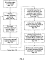
- In addition, a method is disclosed and illustrated in
Fig. 5 for simulating an operation of a gas turbine engine on a computer system in communication with or as part of a FADEC. The method includesstep 102 of simulating, in the computing system, an engine state. In each delta time DT, being the FADEC sampling rate, the FADEC performing: step 104 of sensing the simulated engine state from the computing system; step 106 of determining how the sensed state differs from a predetermined engine state; and step 108 of outputting engine control commands intended for achieving the predetermined state. - In each delta time DT, the computing system performs
step 110 of receiving the FADEC output; step 112 of utilizing the output in an mxm Jacobian Block, having m active balances; and step 114 of performing a reduced balance simulation. The reduced balance simulation includesstep 116 of analyzing fewer than m columns of the Block, the analysis of each column defining a Rolling Jacobian Pass; step 118 of utilizing output from the Rolling Jacobian Passes in the Jacobian Block, to define an updated simulated engine state; and step 120 of communicating the updated simulated engine state to the FADEC. - Step 122 provides for repeating the reduced balanced simulation steps until all m Rolling Jacobian passes have been completed. Thereafter, the reduced balance analysis cycles back to the first selected column for which the Rolling Jacobian was completed, and the analysis continues through the cycle. The FADEC is sensing the simulated engine state and applies control laws to achieve desired modifications. It can be appreciated that the Jacobian Block is effectively a living matrix in that parameters are constantly changing during the analysis cycle. The changes in any one column are directly analyzed by the simulator at the next iterative pass that touches upon that column.
- According to the disclosed method, the number of Rolling Jacobian Passes completed in a delta time DT depends upon: the relative influence of each Rolling Jacobian Pass; and the number of Rolling Jacobian Passes the simulator is capable of completing in the delta time DT. The system performs a maximum of n iteration passes per delta time DT, and the number of iteration passes required for completing the full Block generation is greater than n.
- Further, according to the method, the relative influence of each Rolling Jacobian Pass is determined empirically. The number of Rolling Jacobian Passes which can be completed in a delta time DT is also determined empirically. The simulated sensed state defines, e.g., engine temperatures, pressures. In addition, The FADEC controls engine control surfaces, and air and fuel flow rates. Specifically, the FADEC applies control laws to the engine after applying the control laws to the simulated engine.
- According to an embodiment of the method, the FADEC is simulated. Alternatively, the FADEC and engine are both simulated.
- The benefits of the different embodiments performed by the method are the same as those of the apparatus for simulating an operation of a gas turbine engine, disclosed above.
- The term "about" is intended to include the degree of error associated with measurement of the particular quantity based upon the equipment available at the time of filing the application. For example, "about" can include a range of ± 8% or 5%, or 2% of a given value.
- The terminology used herein is for the purpose of describing particular embodiments only and is not intended to be limiting of the present disclosure. As used herein, the singular forms "a", "an" and "the" are intended to include the plural forms as well, unless the context clearly indicates otherwise. It will be further understood that the terms "comprises" and/or "comprising", when used in this specification, specify the presence of stated features, integers, steps, operations, elements, and/or components, but do not preclude the presence or addition of one or more other features, integers, steps, operations, element components, and/or groups thereof.
- While the present disclosure has been described with reference to an exemplary embodiment or embodiments, it will be understood by those skilled in the art that various changes may be made and equivalents may be substituted for elements thereof without departing from the scope of the present disclosure. In addition, many modifications may be made to adapt a particular situation or material to the teachings of the present disclosure without departing from the essential scope thereof. Therefore, it is intended that the present disclosure not be limited to the particular embodiment disclosed as the best mode contemplated for carrying out this present disclosure, but that the present disclosure will include all embodiments falling within the scope of the claims.
Claims (11)
- A method for simulating an operation of a gas turbine engine on an engine simulator in communication with a FADEC, the method comprising:simulating, in the computing system, an engine state;wherein in each delta time (DT):(1) the FADEC performs:sensing the simulated engine state from the computing system;determining a difference between the sensed state and a predetermined engine state;outputting engine control commands intended for achieving the predetermined state; and(2) the engine simulator performing:receiving the FADEC output;utilizing the output in an mxm Jacobian Block, having m active balances; andperforming a reduced balance simulation, including:analyzing fewer than m columns of the Block, the analysis of each column defining a Rolling Jacobian Pass; andutilizing output from the Rolling Jacobian Passes in the Block, to define an updated simulated engine state.
- The method of claim 1, where the number of Rolling Jacobian Passes completed in a delta time DT depends upon:the relative influence of each Rolling Jacobian Pass; andthe number of Rolling Jacobian Passes the simulator is capable of completing in the delta time DT.
- The method of claim 2, wherein the system performs a maximum of n iteration passes per delta time DT, and the number of iteration passes required for completing the full Block generation is greater than n.
- The method of any preceding claim, wherein for an r x r Jacobian Block, the maximum number of Rolling Jacobian Passes is r.
- The method of claim 2 or any claim dependent thereon, where the relative influence of each Rolling Jacobian Pass is determined empirically.
- The method of claim 3 or any claim dependent thereon, where the number of Rolling Jacobian Passes which can be completed in a delta time DT is determined empirically.
- The method of any preceding claim, where the simulated sensed state defines engine temperatures, pressures, air and fuel flow rates.
- The method of any preceding claim, where the FADEC controls engine control surfaces, air and fuel flow rates.
- The method of any preceding claim, where the FADEC is simulated.
- A system for carrying out the method of any preceding claim, comprising:a computing system and a FADEC in electronic communication therewith, the computer system is configured to simulate an engine state;wherein, in each delta time (DT):(1) the FADEC is configured to:sense the simulated engine state from the computing system;determine a difference between the sensed state and a predetermined engine state; andoutput engine control commands for achieving the predetermined state;(2) the computing system is further configured to:receive the FADEC output;utilize the output in an mxm Jacobian Block, having m active balances; and perform a reduced balance simulation, wherein:fewer than m columns of the Block are analyzed, the analysis of each column defining a Rolling Jacobian Pass; andoutput from the Rolling Jacobian Passes is utilized in the Block, to define an updated simulated engine state.
- A gas turbine engine including the system of claim 10, where the FADEC is configured to change engine parameters after applying the engine parameters to the simulated engine.
Applications Claiming Priority (1)
| Application Number | Priority Date | Filing Date | Title |
|---|---|---|---|
| US15/296,859 US20180107176A1 (en) | 2016-10-18 | 2016-10-18 | System and method for simulating an operation of a gas turbine engine |
Publications (1)
| Publication Number | Publication Date |
|---|---|
| EP3312746A1 true EP3312746A1 (en) | 2018-04-25 |
Family
ID=60190578
Family Applications (1)
| Application Number | Title | Priority Date | Filing Date |
|---|---|---|---|
| EP17197013.0A Withdrawn EP3312746A1 (en) | 2016-10-18 | 2017-10-18 | System and method for simulating an operation of a gas turbine engine on an engine simulator in communication with a fadec |
Country Status (2)
| Country | Link |
|---|---|
| US (1) | US20180107176A1 (en) |
| EP (1) | EP3312746A1 (en) |
Cited By (1)
| Publication number | Priority date | Publication date | Assignee | Title |
|---|---|---|---|---|
| CN110296000A (en) * | 2019-04-30 | 2019-10-01 | 哈尔滨工程大学 | One inter-species SAPMAC method gas turbine steady operation line planing method |
Families Citing this family (5)
| Publication number | Priority date | Publication date | Assignee | Title |
|---|---|---|---|---|
| US20180216466A1 (en) * | 2016-10-14 | 2018-08-02 | Pw Power Systems, Inc. | Methods and systems for rotating component balancing |
| CN109918839B (en) * | 2019-03-27 | 2020-06-09 | 南京航空航天大学 | Modeling method and infrared radiation prediction method for turbofan engine with pilot nozzle |
| CN110513198B (en) * | 2019-08-13 | 2021-07-06 | 大连理工大学 | Active fault-tolerant control method for turbofan engine control system |
| CN110929397B (en) * | 2019-11-20 | 2023-06-30 | 中国人民解放军海军工程大学 | Extrapolation method of low speed characteristic line of gas turbine based on zero speed characteristic line |
| US11333082B2 (en) * | 2020-06-12 | 2022-05-17 | General Electric Company | Systems and methods for determination of gas turbine fuel split for head end temperature control |
-
2016
- 2016-10-18 US US15/296,859 patent/US20180107176A1/en not_active Abandoned
-
2017
- 2017-10-18 EP EP17197013.0A patent/EP3312746A1/en not_active Withdrawn
Non-Patent Citations (3)
| Title |
|---|
| DE LEÓN F ET AL: "Iterative solvers in the Newton power flow problem: preconditioners, inexact solutions, and partial Jacobian updates", IEE PROCEEDINGS: GENERATION, TRANSMISSION AND DISTRIBUT, INSTITUTION OF ELECTRICAL ENGINEERS, GB, vol. 149, no. 4, 15 July 2002 (2002-07-15), pages 479 - 484, XP006018445, ISSN: 1350-2360, DOI: 10.1049/IP-GTD:20020172 * |
| LEITNER J ET AL: "A full authority helicopter adaptive neuro-controller", AEROSPACE CONFERENCE, 1998 IEEE SNOWMASS AT ASPEN, CO, USA 21-28 MARCH 1998, NEW YORK, NY, USA,IEEE, US, vol. 2, 21 March 1998 (1998-03-21), pages 117 - 126, XP010287123, ISBN: 978-0-7803-4311-5, DOI: 10.1109/AERO.1998.687902 * |
| NJAKA C E ET AL: "Towards an advanced nonlinear rotorcraft flight control system design", DIGITAL AVIONICS SYSTEMS CONFERENCE, 1994. 13TH DASC., AIAA/IEEE PHOENIX, AZ, USA 30 OCT.-3 NOV. 1, NEW YORK, NY, USA,IEEE, 30 October 1994 (1994-10-30), pages 190 - 197, XP010127139, ISBN: 978-0-7803-2425-1, DOI: 10.1109/DASC.1994.369483 * |
Cited By (1)
| Publication number | Priority date | Publication date | Assignee | Title |
|---|---|---|---|---|
| CN110296000A (en) * | 2019-04-30 | 2019-10-01 | 哈尔滨工程大学 | One inter-species SAPMAC method gas turbine steady operation line planing method |
Also Published As
| Publication number | Publication date |
|---|---|
| US20180107176A1 (en) | 2018-04-19 |
Similar Documents
| Publication | Publication Date | Title |
|---|---|---|
| EP3312746A1 (en) | System and method for simulating an operation of a gas turbine engine on an engine simulator in communication with a fadec | |
| US20250320832A1 (en) | Machine learned aero-thermodynamic engine inlet condition synthesis | |
| US10788399B2 (en) | Apparatus for evaluating turbine engine system stability | |
| US11568099B2 (en) | System and process for designing internal components for a gas turbine engine | |
| EP4249884B1 (en) | Method and apparatus for thrust determination in an aircraft engine | |
| EP3819805B1 (en) | Parametric component design process | |
| EP3664022B1 (en) | Intelligent learning device for part state detection and identification | |
| EP3141725B1 (en) | Control system and method of controlling a variable area gas turbine engine | |
| Wolters et al. | Engine performance simulation of the integrated V2527-Engine Fan | |
| EP3988775B1 (en) | Methods and systems for determining a synthesized engine parameter | |
| Visser et al. | A generic approach for gas turbine adaptive modeling | |
| Visser et al. | TERTS: A generic real-time gas turbine simulation environment | |
| Nocture et al. | Study of high pressure compressor performances in windmilling conditions by three complementary approaches: experiment, LBM and 1D modeling | |
| SZUCH | Models for Jet Engine Systems Part I Techniques for Jet Engine Systems Modeling | |
| Villarreal-Valderrama et al. | Applicability of correlational data-mining to small-scale turbojet performance map generation | |
| EP4474616B1 (en) | A method and system for optimizing the assembly of rotating hardware in gas turbine engines using artificial neural networks | |
| EP4524386A1 (en) | Built-in test of actively controlled fuel nozzles | |
| Evans et al. | Accounting for Uncontrolled Variations in Low-Speed Turbine Experiments | |
| Röell | Test-cell & On-wing Turbofan Performance Comparison at KLM Engine Services | |
| Bauer et al. | Fully automated model based performance analysis procedure for online and offline applications | |
| Curry et al. | Propulsion directorate/control and engine health management (CEHM): Real-time turbofan engine simulation | |
| Alihosseini et al. | Design and Developement of a Microjet Engine Indoor Test Cell | |
| Covert | Gas Turbine Engine Performance Determination | |
| KOOI et al. | Application of electronically scanned pressure measurement system for engine simulation tests in the German-Dutch Wind Tunnel |
Legal Events
| Date | Code | Title | Description |
|---|---|---|---|
| PUAI | Public reference made under article 153(3) epc to a published international application that has entered the european phase |
Free format text: ORIGINAL CODE: 0009012 |
|
| STAA | Information on the status of an ep patent application or granted ep patent |
Free format text: STATUS: THE APPLICATION HAS BEEN PUBLISHED |
|
| AK | Designated contracting states |
Kind code of ref document: A1 Designated state(s): AL AT BE BG CH CY CZ DE DK EE ES FI FR GB GR HR HU IE IS IT LI LT LU LV MC MK MT NL NO PL PT RO RS SE SI SK SM TR |
|
| AX | Request for extension of the european patent |
Extension state: BA ME |
|
| STAA | Information on the status of an ep patent application or granted ep patent |
Free format text: STATUS: THE APPLICATION IS DEEMED TO BE WITHDRAWN |
|
| 18D | Application deemed to be withdrawn |
Effective date: 20181026 |