EP3312529A1 - Heat exchanger, magnetic heat-pump device, and method for manufacturing heat exchanger - Google Patents
Heat exchanger, magnetic heat-pump device, and method for manufacturing heat exchanger Download PDFInfo
- Publication number
- EP3312529A1 EP3312529A1 EP16811768.7A EP16811768A EP3312529A1 EP 3312529 A1 EP3312529 A1 EP 3312529A1 EP 16811768 A EP16811768 A EP 16811768A EP 3312529 A1 EP3312529 A1 EP 3312529A1
- Authority
- EP
- European Patent Office
- Prior art keywords
- heat exchanger
- assembly
- wires
- twisting
- cover layer
- Prior art date
- Legal status (The legal status is an assumption and is not a legal conclusion. Google has not performed a legal analysis and makes no representation as to the accuracy of the status listed.)
- Granted
Links
Images





Classifications
-
- F—MECHANICAL ENGINEERING; LIGHTING; HEATING; WEAPONS; BLASTING
- F25—REFRIGERATION OR COOLING; COMBINED HEATING AND REFRIGERATION SYSTEMS; HEAT PUMP SYSTEMS; MANUFACTURE OR STORAGE OF ICE; LIQUEFACTION SOLIDIFICATION OF GASES
- F25B—REFRIGERATION MACHINES, PLANTS OR SYSTEMS; COMBINED HEATING AND REFRIGERATION SYSTEMS; HEAT PUMP SYSTEMS
- F25B21/00—Machines, plants or systems, using electric or magnetic effects
-
- B—PERFORMING OPERATIONS; TRANSPORTING
- B29—WORKING OF PLASTICS; WORKING OF SUBSTANCES IN A PLASTIC STATE IN GENERAL
- B29C—SHAPING OR JOINING OF PLASTICS; SHAPING OF MATERIAL IN A PLASTIC STATE, NOT OTHERWISE PROVIDED FOR; AFTER-TREATMENT OF THE SHAPED PRODUCTS, e.g. REPAIRING
- B29C48/00—Extrusion moulding, i.e. expressing the moulding material through a die or nozzle which imparts the desired form; Apparatus therefor
- B29C48/15—Extrusion moulding, i.e. expressing the moulding material through a die or nozzle which imparts the desired form; Apparatus therefor incorporating preformed parts or layers, e.g. extrusion moulding around inserts
- B29C48/151—Coating hollow articles
-
- C—CHEMISTRY; METALLURGY
- C09—DYES; PAINTS; POLISHES; NATURAL RESINS; ADHESIVES; COMPOSITIONS NOT OTHERWISE PROVIDED FOR; APPLICATIONS OF MATERIALS NOT OTHERWISE PROVIDED FOR
- C09D—COATING COMPOSITIONS, e.g. PAINTS, VARNISHES OR LACQUERS; FILLING PASTES; CHEMICAL PAINT OR INK REMOVERS; INKS; CORRECTING FLUIDS; WOODSTAINS; PASTES OR SOLIDS FOR COLOURING OR PRINTING; USE OF MATERIALS THEREFOR
- C09D119/00—Coating compositions based on rubbers, not provided for in groups C09D107/00 - C09D117/00
-
- C—CHEMISTRY; METALLURGY
- C09—DYES; PAINTS; POLISHES; NATURAL RESINS; ADHESIVES; COMPOSITIONS NOT OTHERWISE PROVIDED FOR; APPLICATIONS OF MATERIALS NOT OTHERWISE PROVIDED FOR
- C09D—COATING COMPOSITIONS, e.g. PAINTS, VARNISHES OR LACQUERS; FILLING PASTES; CHEMICAL PAINT OR INK REMOVERS; INKS; CORRECTING FLUIDS; WOODSTAINS; PASTES OR SOLIDS FOR COLOURING OR PRINTING; USE OF MATERIALS THEREFOR
- C09D123/00—Coating compositions based on homopolymers or copolymers of unsaturated aliphatic hydrocarbons having only one carbon-to-carbon double bond; Coating compositions based on derivatives of such polymers
- C09D123/02—Coating compositions based on homopolymers or copolymers of unsaturated aliphatic hydrocarbons having only one carbon-to-carbon double bond; Coating compositions based on derivatives of such polymers not modified by chemical after-treatment
- C09D123/04—Homopolymers or copolymers of ethene
- C09D123/06—Polyethylene
-
- C—CHEMISTRY; METALLURGY
- C09—DYES; PAINTS; POLISHES; NATURAL RESINS; ADHESIVES; COMPOSITIONS NOT OTHERWISE PROVIDED FOR; APPLICATIONS OF MATERIALS NOT OTHERWISE PROVIDED FOR
- C09D—COATING COMPOSITIONS, e.g. PAINTS, VARNISHES OR LACQUERS; FILLING PASTES; CHEMICAL PAINT OR INK REMOVERS; INKS; CORRECTING FLUIDS; WOODSTAINS; PASTES OR SOLIDS FOR COLOURING OR PRINTING; USE OF MATERIALS THEREFOR
- C09D127/00—Coating compositions based on homopolymers or copolymers of compounds having one or more unsaturated aliphatic radicals, each having only one carbon-to-carbon double bond, and at least one being terminated by a halogen; Coating compositions based on derivatives of such polymers
- C09D127/02—Coating compositions based on homopolymers or copolymers of compounds having one or more unsaturated aliphatic radicals, each having only one carbon-to-carbon double bond, and at least one being terminated by a halogen; Coating compositions based on derivatives of such polymers not modified by chemical after-treatment
- C09D127/04—Coating compositions based on homopolymers or copolymers of compounds having one or more unsaturated aliphatic radicals, each having only one carbon-to-carbon double bond, and at least one being terminated by a halogen; Coating compositions based on derivatives of such polymers not modified by chemical after-treatment containing chlorine atoms
- C09D127/06—Homopolymers or copolymers of vinyl chloride
-
- C—CHEMISTRY; METALLURGY
- C09—DYES; PAINTS; POLISHES; NATURAL RESINS; ADHESIVES; COMPOSITIONS NOT OTHERWISE PROVIDED FOR; APPLICATIONS OF MATERIALS NOT OTHERWISE PROVIDED FOR
- C09D—COATING COMPOSITIONS, e.g. PAINTS, VARNISHES OR LACQUERS; FILLING PASTES; CHEMICAL PAINT OR INK REMOVERS; INKS; CORRECTING FLUIDS; WOODSTAINS; PASTES OR SOLIDS FOR COLOURING OR PRINTING; USE OF MATERIALS THEREFOR
- C09D127/00—Coating compositions based on homopolymers or copolymers of compounds having one or more unsaturated aliphatic radicals, each having only one carbon-to-carbon double bond, and at least one being terminated by a halogen; Coating compositions based on derivatives of such polymers
- C09D127/02—Coating compositions based on homopolymers or copolymers of compounds having one or more unsaturated aliphatic radicals, each having only one carbon-to-carbon double bond, and at least one being terminated by a halogen; Coating compositions based on derivatives of such polymers not modified by chemical after-treatment
- C09D127/12—Coating compositions based on homopolymers or copolymers of compounds having one or more unsaturated aliphatic radicals, each having only one carbon-to-carbon double bond, and at least one being terminated by a halogen; Coating compositions based on derivatives of such polymers not modified by chemical after-treatment containing fluorine atoms
-
- F—MECHANICAL ENGINEERING; LIGHTING; HEATING; WEAPONS; BLASTING
- F25—REFRIGERATION OR COOLING; COMBINED HEATING AND REFRIGERATION SYSTEMS; HEAT PUMP SYSTEMS; MANUFACTURE OR STORAGE OF ICE; LIQUEFACTION SOLIDIFICATION OF GASES
- F25B—REFRIGERATION MACHINES, PLANTS OR SYSTEMS; COMBINED HEATING AND REFRIGERATION SYSTEMS; HEAT PUMP SYSTEMS
- F25B41/00—Fluid-circulation arrangements
- F25B41/40—Fluid line arrangements
-
- F—MECHANICAL ENGINEERING; LIGHTING; HEATING; WEAPONS; BLASTING
- F28—HEAT EXCHANGE IN GENERAL
- F28F—DETAILS OF HEAT-EXCHANGE AND HEAT-TRANSFER APPARATUS, OF GENERAL APPLICATION
- F28F1/00—Tubular elements; Assemblies of tubular elements
- F28F1/10—Tubular elements and assemblies thereof with means for increasing heat-transfer area, e.g. with fins, with projections, with recesses
- F28F1/40—Tubular elements and assemblies thereof with means for increasing heat-transfer area, e.g. with fins, with projections, with recesses the means being only inside the tubular element
- F28F1/405—Tubular elements and assemblies thereof with means for increasing heat-transfer area, e.g. with fins, with projections, with recesses the means being only inside the tubular element and being formed of wires
-
- F—MECHANICAL ENGINEERING; LIGHTING; HEATING; WEAPONS; BLASTING
- F28—HEAT EXCHANGE IN GENERAL
- F28F—DETAILS OF HEAT-EXCHANGE AND HEAT-TRANSFER APPARATUS, OF GENERAL APPLICATION
- F28F21/00—Constructions of heat-exchange apparatus characterised by the selection of particular materials
-
- B—PERFORMING OPERATIONS; TRANSPORTING
- B29—WORKING OF PLASTICS; WORKING OF SUBSTANCES IN A PLASTIC STATE IN GENERAL
- B29L—INDEXING SCHEME ASSOCIATED WITH SUBCLASS B29C, RELATING TO PARTICULAR ARTICLES
- B29L2031/00—Other particular articles
- B29L2031/18—Heat-exchangers or parts thereof
-
- F—MECHANICAL ENGINEERING; LIGHTING; HEATING; WEAPONS; BLASTING
- F25—REFRIGERATION OR COOLING; COMBINED HEATING AND REFRIGERATION SYSTEMS; HEAT PUMP SYSTEMS; MANUFACTURE OR STORAGE OF ICE; LIQUEFACTION SOLIDIFICATION OF GASES
- F25B—REFRIGERATION MACHINES, PLANTS OR SYSTEMS; COMBINED HEATING AND REFRIGERATION SYSTEMS; HEAT PUMP SYSTEMS
- F25B2321/00—Details of machines, plants or systems, using electric or magnetic effects
- F25B2321/002—Details of machines, plants or systems, using electric or magnetic effects by using magneto-caloric effects
-
- F—MECHANICAL ENGINEERING; LIGHTING; HEATING; WEAPONS; BLASTING
- F25—REFRIGERATION OR COOLING; COMBINED HEATING AND REFRIGERATION SYSTEMS; HEAT PUMP SYSTEMS; MANUFACTURE OR STORAGE OF ICE; LIQUEFACTION SOLIDIFICATION OF GASES
- F25B—REFRIGERATION MACHINES, PLANTS OR SYSTEMS; COMBINED HEATING AND REFRIGERATION SYSTEMS; HEAT PUMP SYSTEMS
- F25B2321/00—Details of machines, plants or systems, using electric or magnetic effects
- F25B2321/002—Details of machines, plants or systems, using electric or magnetic effects by using magneto-caloric effects
- F25B2321/0021—Details of machines, plants or systems, using electric or magnetic effects by using magneto-caloric effects with a static fixed magnet
-
- F—MECHANICAL ENGINEERING; LIGHTING; HEATING; WEAPONS; BLASTING
- F28—HEAT EXCHANGE IN GENERAL
- F28F—DETAILS OF HEAT-EXCHANGE AND HEAT-TRANSFER APPARATUS, OF GENERAL APPLICATION
- F28F2255/00—Heat exchanger elements made of materials having special features or resulting from particular manufacturing processes
- F28F2255/16—Heat exchanger elements made of materials having special features or resulting from particular manufacturing processes extruded
-
- Y—GENERAL TAGGING OF NEW TECHNOLOGICAL DEVELOPMENTS; GENERAL TAGGING OF CROSS-SECTIONAL TECHNOLOGIES SPANNING OVER SEVERAL SECTIONS OF THE IPC; TECHNICAL SUBJECTS COVERED BY FORMER USPC CROSS-REFERENCE ART COLLECTIONS [XRACs] AND DIGESTS
- Y02—TECHNOLOGIES OR APPLICATIONS FOR MITIGATION OR ADAPTATION AGAINST CLIMATE CHANGE
- Y02B—CLIMATE CHANGE MITIGATION TECHNOLOGIES RELATED TO BUILDINGS, e.g. HOUSING, HOUSE APPLIANCES OR RELATED END-USER APPLICATIONS
- Y02B30/00—Energy efficient heating, ventilation or air conditioning [HVAC]
Definitions
- the present invention relates to a heat exchanger to be used in a magnetic heat pump device using a magnetocaloric effect, a magnetic heat pump device including the heat exchanger, and a manufacturing method of the heat exchanger.
- a heat exchanger including: an assembly obtained by overlapping a plurality of columnar magnetic bodies in a direction intersecting its longitudinal direction; and a cylindrical casing having the assembly inserted thereinto (for example, see Patent Document 1).
- Patent Document 1 JP 2013-64588 A
- Problems to be solved by the present invention include providing a heat exchanger capable of improving a heat exchange efficiency, a magnetic heat pump device including the heat exchanger, and a manufacturing method of the heat exchanger.
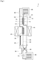
- Figs. 1 and 2 are diagrams showing an overall configuration of a magnetic heat pump device of this embodiment
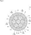
- Figs. 3 and 4 are diagrams showing an MCM heat exchanger of this embodiment.
- a magnetic heat pump device 1 of this embodiment is a heat pump device using a magnetocaloric effect and includes, as shown in Figs. 1 and 2 , first and second MCM heat exchangers 10 and 20, a piston 30, a permanent magnet 40, a low temperature side heat exchanger 50, a high temperature side heat exchanger 60, a pump 70, pipes 81 to 84, and a switching valve 90.
- the first and second MCM heat exchangers 10 and 20 of this embodiment correspond to an example of the heat exchanger of the invention
- the piston 30 and the permanent magnet 40 of this embodiment correspond to an example of a magnetic changer of the invention
- the low temperature side heat exchanger 50 and the high temperature side heat exchanger 60 correspond to an example of first and second external heat exchangers of the invention
- the pipes 81 to 84 of this embodiment correspond to an example of a pipe of the invention
- the pump 70 and the switching valve 90 of this embodiment correspond to an example of a fluid supplier of the invention.
- the first MCM heat exchanger 10 includes, as shown in Figs. 3 and 4 , an assembly (an aggregate) 11 including a plurality of wires 12, a cover layer 13 covering the assembly 11, and adapters 16 and 17 connected to both ends of the cover layer 13. Since the first MCM heat exchanger 10 and the second MCM heat exchanger 20 have the same structure, a configuration of the first MCM heat exchanger 10 will be described only below, and a configuration of the second MCM heat exchanger 20 will be omitted.
- the wire 12 is composed of a magnetocaloric material (MCM) having a magnetocaloric effect.
- MCM magnetocaloric material
- the MCM of which the wire 12 is composed not particularly limited as long as the MCM is a magnetic body.
- a magnetic body having a Curie temperature (Curie point) in a normal temperature range of about 10°C to 30°C and exhibiting a high magnetocaloric effect in a normal temperature range is desirable.
- Specific examples of such MCMs include gadolinium (Gd), gadolinium alloy, lanthanum-iron-silicon (La-Fe-Si) based compounds, and the like.
- the wire 12 of this embodiment is a wire member having a circular cross-sectional shape. As long as it is possible to form a passage 111 (to be described later) between the wires 12 at the time of bundling the wires 12, the wire 12 may have a cross-sectional shape other than the circular cross-sectional shape.
- the assembly 11 is formed by bundling the plurality of wires 12.
- the plurality of wires 12 are bundled (overlapped) in a direction intersecting the longitudinal direction of the wire 12.
- the plurality of wires 12 are adjacent to each other so that the side surfaces of the wires 12 contact each other.
- the passage 111 is formed between the side surfaces of the wires 12.
- the assembly 11 includes seven wires 12 in the example shown in Fig. 4 , but in fact, the assembly 11 is formed by bundling thousands to tens of thousands of the wires 12.
- the assembly 11 shown in Figs. 3 and 4 is formed by simply bundling the plurality of wires 12, but the configuration of the assembly is not particularly limited thereto.
- an assembly 11B may be formed by twisting a plurality of wires 12B as in an MCM heat exchanger 10B shown in Figs. 5 and 6 .
- Fig. 5 is an exploded perspective view showing another configuration of the MCM heat exchanger of this embodiment
- Fig. 6 is a cross-sectional view taken along a line VI-VI of Fig. 5
- Fig. 7(a) is a side view of the assembly used in the MCM heat exchanger shown in Fig. 5
- Fig. 7(b) is a side view of one of wires constituting the assembly shown in Fig. 7(a) .
- the assembly 11B shown in Figs. 5 and 6 is formed by bundling the plurality of wires 12B in a direction intersecting the longitudinal direction and twisting (stranding) them together. Since the side surfaces of the adjacent twisted wires 12B contact each other, a passage 111B is formed therebetween.
- the assembly 11B includes nineteen wires 12B in the examples shown in Figs. 5 and 6 , but in fact, the assembly 11B is formed by bundling several hundreds to several tens of thousands of the wires 12B.
- An outer diameter D (see Fig. 7(a) ) of the assembly 11B is not particularly limited, but for example, 30 mm or less is desirable from the viewpoint of ensuring the magnetic flux density.
- the plurality of wires 12B are twisted by collective twisting.
- a method of twisting the plurality of wires 12B of the assembly 11B is not particularly limited, and concentric twisting or composite twisting may be used.
- the collective twisting is a twisting method in which the plurality of wires 12B are bundled together and twisted in the same direction around the axis of the assembly 11B.
- the concentric twisting is a twisting method in which the plurality of wires 12B are concentrically twisted around a core wire corresponding to a center.
- the composite twisting is a twisting method in which child twisted wires each of which is obtained by twisting the plurality of wires 12B by concentric twisting or collective twisting are further twisted by concentric twisting or collective twisting.
- the core wire of concentric twisting may be formed as one wire 12B or may be formed by twisting the plurality of wires 12B. Further, a direction of twisting the plurality of wires 12B may be a right direction or a left direction.
- the wire diameter R of the wire 12B (see Fig. 7(b) ) is not particularly limited, but for example, 0.01 to 1 mm is desirable and 0.02 to 0.5 mm is more desirable.
- the plurality of wires 12B constituting the assembly 11B may have the substantially same wire diameters or may have different wire diameters.
- the twisting pitch P (see Fig. 7(b) ) for twisting the wires 12B is desirably 14 to 450 mm. When the twisting pitch P is smaller than the lower limit value, there is a concern that the passage may be crushed since the wires are compressed and deformed.
- twisting pitch P is the length of the wire 12B in the longitudinal direction while one wire 12B goes one revolution around the assembly 11B.
- the assembly 11 of the wire 12 is covered (coated) by the cover layer 13.
- the cover layer 13 includes a tubular portion 14 and a filling portion 15.
- the tubular portion 14 surrounds the periphery of the assembly 11 in a cylindrical shape.
- the filling portion 15 is charged to fill a gap between the outer periphery of the assembly 11 and the inner periphery of the tubular portion 14. That is, in this embodiment, the filling portion 15 fills between the wires 12a located at the outermost periphery of the assembly 11 and the tubular portion 14 so as to block a gap between the outermost wires 12a and the tubular portion 14.
- the cover layer 13 is composed of, for example, a resin material such as polyvinyl chloride, polyethylene, crosslinked polyethylene, silicone rubber, and fluororesin, and the tubular portion 14 and the filling portion 15 are integrally formed.
- the "integral formation" of this embodiment means that the members are not separated, but are formed as an integral structure by the same resin material. Even when the assembly 11B formed by twisting the plurality of wires 12B is used instead of the assembly 11, the assembly 11B is covered by the cover layer 13 including the tubular portion 14 and the filling portion 15, and the filling portion 15 fills between the outer periphery of the assembly 11B and the tubular portion 14 (see Fig. 6 ).
- the cover layer 13 includes: a first opening 131 located at one end; and a second opening 132 located at the other end.
- a direction CL from the first opening 131 to the second opening 132 substantially matches the extending direction of the assembly 11.
- the first adapter 16 is connected to one end of the cover layer 13.
- the second adapter 17 is also connected to the other end of the cover layer 13.
- first and second adapters 16 and 17 for example, a heat shrinkable tube or the like can be exemplified.
- the first and second adapters 16 and 17 may be formed as resin products, or the first and second adapters 16 and 17 may be composed of a metal material.
- the first adapter 16 includes a first connection port 161 smaller than the first opening 131. As shown in Fig. 1 , the first connection port 161 communicates with the low temperature side heat exchanger 50 through the first low temperature side pipe 81.
- the second adapter 17 also includes a second connection port 171 smaller than the second opening 132.
- the second connection port 171 communicates with the high temperature side heat exchanger 60 through the first high temperature side pipe 83.
- the centers of the first and second connection ports 161 and 171 are located to be coaxial with the center of the assembly 11.
- the cover layer 23 of the second MCM heat exchanger 20 also covers the assembly 21 including the plurality of wires 22, and the first and second adapters are connected to both ends of the cover layer 23.
- the first connection port 261 of the first adapter communicates with the low temperature side heat exchanger 50 through the second low temperature side pipe 82.
- the second connection port 271 of the second adapter communicates with the high temperature side heat exchanger 60 through the second high temperature side pipe 84.
- the wire 22 of the second MCM heat exchanger 20 has the same configuration as that of the wire 12 of the first MCM heat exchanger 10. Further, the cover layer 23 of the second MCM heat exchanger 20 also has the same configuration as that of the cover layer 13 of the first MCM heat exchanger 10. Further, the adapters of the second MCM heat exchanger 20 also have the same configurations as those of the adapters 16 and 17 of the first MCM heat exchanger 10.
- an indoor place is cooled by a heat exchange between the low temperature side heat exchanger 50 and the inside air, and heat is emitted to an outdoor place by a heat exchange between the high temperature side heat exchanger 60 and the outside air.
- the indoor place is warmed by a heat exchange between the high temperature side heat exchanger 60 and the inside air, and heat is absorbed from the outdoor place by a heat exchange between the low temperature side heat exchanger 50 and the outside air.
- a circulation path including four heat exchangers 10, 20, 50, and 60 is formed by two low temperature side pipes 81 and 82 and two high temperature side pipes 83 and 84, and a liquid medium is pressure-fed in the circulation path by the pump 70.
- a liquid medium for example, a liquid such as water, an antifreeze solution, an ethanol solution, or a mixture thereof can be exemplified.
- the liquid medium of this embodiment corresponds to an example of a fluid of the invention.
- the piston 30 can move in a reciprocating manner between a pair of permanent magnets 40 by the actuator 35. Specifically, the piston 30 can move in a reciprocating manner between a "first position" shown in Fig. 1 and a "second position" shown in Fig. 2 .
- the actuator 35 for example, an air cylinder or the like can be exemplified.
- the "first position” is a position of the piston 30 when the first MCM heat exchanger 10 is not interposed between the permanent magnets 40 and the second MCM heat exchanger 20 is interposed between the permanent magnets 40.
- the “second position” is a position of the piston 30 when the first MCM heat exchanger 10 is interposed between the permanent magnets 40 and the second MCM heat exchanger 20 is not interposed between the permanent magnets 40.
- the permanent magnet 40 may be moved in a reciprocating manner by the actuator 35.
- an electromagnet having a coil may be used instead of the permanent magnet 40.
- a mechanism of moving the MCM heat exchangers 10 and 20 or the magnet is not necessary.
- the electromagnet having the coil when used, the magnitude of the magnetic field applied to the wires 12 and 22 may be changed instead of applying/removing of the magnetic field with respect to the wires 12 and 22 of the MCM heat exchangers 10 and 20.
- the switching valve 90 is provided at the first high temperature side pipe 83 and the second high temperature side pipe 84. In synchronization with the operation of the piston 30, the switching valve 90 can switch the liquid medium supply destination of the pump 70 to the first MCM heat exchanger 10 or the second MCM heat exchanger 20 and switch the connection destination of the high temperature side heat exchanger 60 to the second MCM heat exchanger 20 or the first MCM heat exchanger 10.
- a first path (the pump 70 ⁇ the first high temperature side pipe 83 ⁇ the first MCM heat exchanger 10 ⁇ the first low temperature side pipe 81 ⁇ the low temperature side heat exchanger 50 ⁇ the second low temperature side pipe 82 ⁇ the second MCM heat exchanger 20 ⁇ the second high temperature side pipe 84 ⁇ the high temperature side heat exchanger 60 ⁇ the pump 70) is formed by the switching valve 90.
- the liquid medium is cooled by the wire 12 of the first MCM heat exchanger 10 of which a temperature decreases due to a demagnetization, and the liquid medium is supplied to the low temperature side heat exchanger 50 so that the low temperature side heat exchanger 50 is cooled.
- the liquid medium passes through the passage 111 formed between the side surfaces of the wires 12 inside the first MCM heat exchanger 10 so as to contact the wires 12, the liquid medium is cooled by the wires 12. Further, since a gap between the outer periphery of the assembly 11 and the tubular portion 14 is blocked by the filling portion 15 of the cover layer 13, the amount of the liquid medium flowing through the passage 111 between the wires 12 does not decrease.
- the assembly 11B is formed by twisting the plurality of wires 12B (see Figs. 5 and 6 )
- the plurality of wires 12B are held by each other. For this reason, it is possible to suppress a problem in which the wire 12B is moved by an outward pressing force or a friction force caused by the liquid medium.
- the liquid medium is heated by the wire 22 of the second MCM heat exchanger 20 of which a temperature increases due to a magnetization, and the liquid medium is supplied to the high temperature side heat exchanger 60 so that the high temperature side heat exchanger 60 is heated.
- the liquid medium passes through the passage formed between the side surfaces of the wires 22 inside the second MCM heat exchanger 20 so as to contact the wires 22, the liquid medium is heated by the wires 22. Further, since a gap between the outer periphery of the assembly 21 and the tubular portion of the cover layer 23 is blocked by the filling portion of the cover layer 23, the amount of the liquid medium flowing through the passage formed between the wires 22 does not decrease.
- the assembly of the second MCM heat exchanger is formed by twisting the plurality of wires
- the plurality of wires are held by each other. For this reason, it is possible to suppress a problem in which the wire is moved by an outward pressing force or a friction force caused by the liquid medium.
- a second path (the pump 70 ⁇ the second high temperature side pipe 84 ⁇ the second MCM heat exchanger 20 ⁇ the second low temperature side pipe 82 ⁇ the low temperature side heat exchanger 50 ⁇ the first low temperature side pipe 81 ⁇ the first MCM heat exchanger 10 ⁇ the first high temperature side pipe 83 ⁇ the high temperature side heat exchanger 60 ⁇ the pump 70) is formed by the switching valve 90.
- the liquid medium is cooled by the wire 22 of the second MCM heat exchanger 20 of which a temperature decreases due to a demagnetization, and the liquid medium is supplied to the low temperature side heat exchanger 50 so that the low temperature side heat exchanger 50 is cooled.
- the liquid medium passes through the passage formed between the side surfaces of the wires 22 inside the second MCM heat exchanger 20 so as to contact the wires 22, the liquid medium is cooled by the wire 22. Further, since a gap between the outer periphery of the assembly 21 and the tubular portion of the cover layer 23 is blocked by the filling portion of the cover layer 23, the amount of the liquid medium flowing through the passage between the wires 22 does not decrease.
- the assembly of the second MCM heat exchanger is formed by twisting the plurality of wires
- the plurality of wires are held by each other. For this reason, it is possible to suppress a problem in which the wire is moved by an outward pressing force or a friction force caused by the liquid medium.
- the liquid medium is heated by the wire 12 of the first MCM heat exchanger 10 of which a temperature increases due to a magnetization, and the liquid medium is supplied to the high temperature side heat exchanger 60 so that the high temperature side heat exchanger 60 is heated.
- the liquid medium passes through the passage 111 formed between the side surfaces of the wires 12 inside the first MCM heat exchanger 10 so as to contact the wires 12, the liquid medium is heated by the wires 12. Further, since a gap between the outer periphery of the assembly 11 and the tubular portion 14 is blocked by the filling portion 15 of the cover layer 13, the amount of the liquid medium flowing through the passage 111 formed between the wires 12 does not decrease.
- the assembly 11B is formed by twisting the plurality of wires 12B (see Figs. 5 and 6 )
- the plurality of wires 12B are held by each other. For this reason, it is possible to suppress a problem in which the wire 12B is moved by an outward pressing force or a friction force caused by the liquid medium.
- the cover layer 13 includes the first and second openings 131 and 132 and a direction from the first opening 131 to the second opening 132 substantially matches the extending direction of the assembly 11, it is possible to suppress an increase in pressure loss of the liquid medium flowing inside the MCM heat exchanger 10.
- the wire 12B cannot easily radiate and absorb heat. As a result, there is a concern that a heat exchange efficiency between the wire and the liquid medium may be deteriorated. On the contrary, in this embodiment, it is possible to suppress a deterioration in thermal energy exchange efficiency of the MCM heat exchanger.
- the plurality of wires 12B are twisted by concentric twisting, collective twisting, or composite twisting, it is possible to twist the wires 12B while preventing the crushing of the passage 111B.
- Equations (3) and (4) are satisfied, it is possible to twist the wires 12B while further preventing the crushing of the passage 111B.
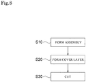
- Fig. 8 is a process diagram showing a manufacturing method of an MCM heat exchanger of this embodiment
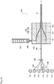
- Fig. 9 is a cross-sectional view showing a resin extrusion covering device used in step S20 of Fig. 8 .
- first MCM heat exchanger 10 and the second MCM heat exchanger 20 have the same structure, only a method of manufacturing the first MCM heat exchanger 10 will be described, and a method of manufacturing the second MCM heat exchanger 20 will be omitted.
- step S10 of Fig. 8 the assembly 11 is formed by bundling the plurality of wires 12.
- the wire 12 is formed in such a manner that a powdered MCM is inserted into a mold and sintered to be formed into a cylindrical member and the cylindrical member is linearly stretched.
- a method of forming the wire 12 is not particularly limited to the above-described method.
- the wire 12 may be formed in such a manner that a casted material is formed into a cylindrical member and the cylindrical member is linearly stretched.
- the assembly 11 is formed by bundling the plurality of wires 12. At this time, the plurality of wires 12 are bundled in a direction intersecting the longitudinal direction of the wire 12. The plurality of wires 12 constituting the assembly 11 are simply bundled and are not fixed to each other by an adhesive or the like.
- step S20 of Fig. 8 the assembly 11 is covered by the cover layer 13 using a resin extrusion covering device 100 shown in Fig. 9 .
- a mold 130 including a nipple 140 and a die 150 is attached to a crosshead 120 of the resin extrusion covering device 100.
- the nipple 140 includes an insertion hole 141 through which the assembly 11 passes. Further, the nipple 140 is disposed inside an insertion hole 151 of the die 150, and a passage 152 through which a melted resin MR passes is formed between the nipple 140 and the die 150.
- the melted resin MR which is heated and kneaded by the extrusion device 110 is supplied to the crosshead 120. Then, the assembly 11 passes through the insertion hole 141 of the nipple 140 and the melted resin MR passes through the passage 152 so that the melted resin is extruded so as to cover the outer periphery of the assembly 11. Then, the melted resin MR is cooled right after the extrusion so that the cover layer 13 is formed. Air cooling or water cooling may be used as a method of cooling the melted resin MR.
- the tubular portion 14 of the cover layer 13 is formed.
- the filling portion 15 of the cover layer 13 is formed.
- step S30 of Fig. 8 the assembly 11 covered by the cover layer 13 is cut into a predetermined length.
- one end of the cover layer 13 is connected to the first low temperature side pipe 81 by the first adapter 16, and the other end of the cover layer 13 is connected to the first high temperature side pipe 83 by the second adapter 17. Accordingly, the first MCM heat exchanger 10 is completed.
- a cutting process in step S30 is not necessary.
- the cover layer 13 is formed by extrusion molding a resin material on the outer periphery of the assembly 11 in the same manner as the covered wire having the twisted wire and the cover layer. For this reason, a gap between the outermost wire 12a and the tubular portion 14 of the cover layer 13 can be easily filled with the filling portion 15.
- step S10 of Fig. 8 the assembly 11B shown in Figs. 5 and 6 may be formed by twisting the plurality of wires 12B as below.
- Fig. 10 is a cross-sectional view showing a twisting device used at the time of manufacturing the MCM heat exchanger shown in Fig. 5 .
- the plurality of prepared wires 12B are bundled in a direction intersecting the longitudinal direction of the wire 12B. Then, the plurality of bundled wires 12B are twisted. Although there are various twisting methods as described above, a known twisting method may be used at the time of twisting the plurality of wires 12B.
- a twisting device 160 which twists the wires 12B delivered from a plurality of delivery bobbins 170 having the wires 12B wound thereon shown in Fig. 10 may be used.
- the twisting device 160 is disposed on the upstream side of the resin extrusion covering device 100.
- the twisting device 160 includes a twisting control plate (not shown) having a plurality of insertion holes (not shown) and can form the assembly 11B in which the plurality of wires 12B are twisted by rotating the twisting control plate in a predetermined twisting direction while passing the wires 12B delivered from the delivery bobbins 170 through the plurality of insertion holes.
- the configuration of the above-described magnetic heat pump device is an example, and the heat exchanger according to the invention may be applied to another magnetic heat pump device of an AMR (Active Magnetic Refrigeration) type.
- AMR Active Magnetic Refrigeration
- the magnetic heat pump device may include one MCM heat exchanger, a magnetic field changer configured to apply a magnetic field to the MCM and change the magnitude of the magnetic field, first and second external heat exchangers which are respectively connected to the MCM heat exchanger through a pipe, and a fluid supplier configured to supply a fluid from the MCM heat exchanger to the first or second external heat exchangers in synchronization with the operation of the magnetic field changer.
- the magnetic heat pump device is applied to the air conditioner for home or an automobile, but the invention is not particularly limited thereto.
- the magnetic heat pump device according to the invention may be used for an application in an extremely low temperature range such as a refrigerator or in a high temperature range to some extent.
- first and second MCM heat exchangers 10 and 20 have the same configurations, but the invention is not particularly limited thereto.
- the heat exchangers may have different configurations.
- the first and second MCM heat exchangers 10 and 20 may use wires having different wire diameters.
- the twisting methods, the twisting directions, or the twisting pitches of the plurality of wires may be different from each other.
- the MCM heat exchanger includes a single assembly, but the invention is not particularly limited thereto.
- a plurality of assemblies may be arranged in series along the extending direction of the MCM heat exchanger.
- the plurality of assemblies may have the same configurations or different configurations.
- the MCM heat exchanger When the magnetic heat pump device is continuously used, the MCM heat exchanger has a temperature gradient in which a temperature is high at the connection side to the high temperature side pipe and a temperature is low at the connection side to the low temperature side pipe.
- the wires constituting the assembly located at the high temperature side among the plurality of assemblies arranged in series are desirably composed of a material having a relatively high Curie point (Curie temperature), and the wires constituting the assembly located at the low temperature side are desirably composed of a material having a relatively low Curie point.
- the wires composed of materials having different Curie points are used in response to the temperature atmosphere in the MCM heat exchanger, the magnetocaloric effect can be exhibited with higher efficiency.
Landscapes
- Engineering & Computer Science (AREA)
- Mechanical Engineering (AREA)
- Chemical & Material Sciences (AREA)
- Physics & Mathematics (AREA)
- Thermal Sciences (AREA)
- General Engineering & Computer Science (AREA)
- Life Sciences & Earth Sciences (AREA)
- Materials Engineering (AREA)
- Wood Science & Technology (AREA)
- Organic Chemistry (AREA)
- Geometry (AREA)
- Hard Magnetic Materials (AREA)
- Heat-Exchange Devices With Radiators And Conduit Assemblies (AREA)
Abstract
Description
- The present invention relates to a heat exchanger to be used in a magnetic heat pump device using a magnetocaloric effect, a magnetic heat pump device including the heat exchanger, and a manufacturing method of the heat exchanger.
- For designated countries that are permitted to be incorporated by reference in the literature, the contents described in Japanese Patent Application No.
2015-123628 2015-200867 - There is known a heat exchanger including: an assembly obtained by overlapping a plurality of columnar magnetic bodies in a direction intersecting its longitudinal direction; and a cylindrical casing having the assembly inserted thereinto (for example, see Patent Document 1).
- Patent Document 1:
JP 2013-64588 A - In the above-described heat exchanger, a gap is formed between a magnetic bodies located at the outermost periphery of the assembly and the inner peripheral surface of the casing. For that reason, since a large amount of a liquid medium flows into the gap and the amount of the liquid medium passing through a passage formed between the magnetic bodies is small, a problem arises in that a heat exchange efficiency is not high.
- Problems to be solved by the present invention include providing a heat exchanger capable of improving a heat exchange efficiency, a magnetic heat pump device including the heat exchanger, and a manufacturing method of the heat exchanger.
-
- [1] A heat exchanger according to the invention is a heat exchanger to be used in a magnetic heat pump device, the heat exchanger comprising: an assembly formed by bundling wires; and a cover layer covering the assembly, wherein each of the wires is composed of a magnetocaloric material having a magnetocaloric effect, and the cover layer includes: a tubular portion surrounding the periphery of the assembly; and a filling portion filling a gap between the outer periphery of the assembly and the tubular portion.
- [2] In the above-described invention, the tubular portion and the filling portion may be integrally formed.
- [3] In the above-described invention, the cover layer may be composed of polyvinyl chloride, polyethylene, crosslinked polyethylene, silicone rubber, or fluororesin.
- [4] In the above-described invention, the cover layer may include: a first opening located at one end; and a second opening located at the other end, and a direction from the first opening to the second opening may substantially match an extending direction of the assembly.
- [5] In the above-described invention, the assembly may be formed by twisting the wires.
- [6] In the above-described invention, the wires may be twisted by concentric twisting, collective twisting, or composite twisting.
- [7] In the above-described invention, following Equations (1) and (2) may be satisfied.


In the above Equation (2), P is a twisting pitch of twisting the wires, and R is a wire diameter of the wire. - [8] A magnetic heat pump device according to the invention is a magnetic heat pump device comprising: at least one of the above-described heat exchangers; a magnetic field changer configured to apply a magnetic field to the magnetocaloric material and change the magnitude of the magnetic field; first and second external heat exchangers respectively connected to the heat exchanger through a pipe; and a fluid supplier configured to supply a fluid from the heat exchanger to the first or second external heat exchanger in synchronization with the operation of the magnetic field changer.
- [9] A manufacturing method of the heat exchanger according to the invention is a manufacturing method of a heat exchanger to be used in a magnetic heat pump device, the manufacturing method comprising: a first step of forming an assembly by bundling wires; and a second step of forming a cover layer to cover the assembly, wherein each of the wires is composed of a magnetocaloric material having a magnetocaloric effect, and the cover layer includes: a tubular portion surrounding the periphery of the assembly; and a filling portion filling a gap between the outer periphery of the assembly and the tubular portion.
- [10] In the above-described invention, the second step may include forming the cover layer by extruding a resin material to the outer periphery of the assembly while moving the assembly.
- [11] In the above-described invention, the first step may include forming the assembly by twisting the wires.
- [12] In the above-described invention, the manufacturing method may comprise a third step of cutting the assembly covered by the cover layer into a predetermined length.
- According to the invention, since a gap between the assembly and the tubular portion is blocked by the filling portion of the cover layer, a large amount of the liquid medium can pass through the passage formed between the wires of the assembly and thus a heat exchange efficiency can be improved.
-
-
Fig. 1 is a diagram showing an overall configuration of a magnetic heat pump device in an embodiment of the invention and is a diagram showing a state where a piston is located at a first position; -
Fig. 2 is a diagram showing an overall configuration of the magnetic heat pump device in the embodiment of the invention and is a diagram showing a state where the piston is located at a second position; -
Fig. 3 is a cross-sectional view of an MCM heat exchanger in the embodiment of the invention and is a cross-sectional view cut along a liquid medium flow direction; -
Fig. 4 is a cross-sectional view taken along a line IV-IV ofFig. 3 ; -
Fig. 5 is an exploded perspective view showing another configuration of the MCM heat exchanger in the embodiment of the invention; -
Fig. 6 is a cross-sectional view taken along a line VI-VI ofFig. 5 ; -
Fig. 7(a) is a side view of an assembly used in the MCM heat exchanger shown inFig. 5 , andFig. 7(b) is a side view of one of wires constituting the assembly shown inFig. 7(a) ; -
Fig. 8 is a process diagram showing a manufacturing method of an MCM heat exchanger in the embodiment of the invention; -
Fig. 9 is a cross-sectional view of a resin extrusion covering device used in step S20 ofFig. 8 ; and -
Fig. 10 is a cross-sectional view showing a twisting device and a resin extrusion covering device used at the time of manufacturing the MCM heat exchanger shown inFig. 5 . - Hereinafter, an embodiment of the invention will be described with reference to the drawings.
-
Figs. 1 and2 are diagrams showing an overall configuration of a magnetic heat pump device of this embodiment, andFigs. 3 and4 are diagrams showing an MCM heat exchanger of this embodiment. - A magnetic
heat pump device 1 of this embodiment is a heat pump device using a magnetocaloric effect and includes, as shown inFigs. 1 and2 , first and secondMCM heat exchangers piston 30, apermanent magnet 40, a low temperatureside heat exchanger 50, a high temperatureside heat exchanger 60, apump 70,pipes 81 to 84, and aswitching valve 90. - The first and second
MCM heat exchangers piston 30 and thepermanent magnet 40 of this embodiment correspond to an example of a magnetic changer of the invention, the low temperatureside heat exchanger 50 and the high temperatureside heat exchanger 60 correspond to an example of first and second external heat exchangers of the invention, thepipes 81 to 84 of this embodiment correspond to an example of a pipe of the invention, and thepump 70 and theswitching valve 90 of this embodiment correspond to an example of a fluid supplier of the invention. - The first
MCM heat exchanger 10 includes, as shown inFigs. 3 and4 , an assembly (an aggregate) 11 including a plurality ofwires 12, acover layer 13 covering theassembly 11, andadapters cover layer 13. Since the firstMCM heat exchanger 10 and the secondMCM heat exchanger 20 have the same structure, a configuration of the firstMCM heat exchanger 10 will be described only below, and a configuration of the secondMCM heat exchanger 20 will be omitted. - The
wire 12 is composed of a magnetocaloric material (MCM) having a magnetocaloric effect. When a magnetic field is applied to thewire 12 composed of the MCM, the electron spins are aligned. Accordingly, the magnetic entropy decreases, and thewire 12 generates heat so that its temperature rises. Meanwhile, when the magnetic field is removed from thewire 12, the electron spins become disordered. Accordingly, the magnetic entropy increases, and thewire 12 absorbs heat as its temperature falls. - The MCM of which the
wire 12 is composed not particularly limited as long as the MCM is a magnetic body. However, for example, a magnetic body having a Curie temperature (Curie point) in a normal temperature range of about 10°C to 30°C and exhibiting a high magnetocaloric effect in a normal temperature range is desirable. Specific examples of such MCMs include gadolinium (Gd), gadolinium alloy, lanthanum-iron-silicon (La-Fe-Si) based compounds, and the like. - The
wire 12 of this embodiment is a wire member having a circular cross-sectional shape. As long as it is possible to form a passage 111 (to be described later) between thewires 12 at the time of bundling thewires 12, thewire 12 may have a cross-sectional shape other than the circular cross-sectional shape. - The
assembly 11 is formed by bundling the plurality ofwires 12. The plurality ofwires 12 are bundled (overlapped) in a direction intersecting the longitudinal direction of thewire 12. In other words, the plurality ofwires 12 are adjacent to each other so that the side surfaces of thewires 12 contact each other. As a result, thepassage 111 is formed between the side surfaces of thewires 12. In order to facilitate understanding, theassembly 11 includes sevenwires 12 in the example shown inFig. 4 , but in fact, theassembly 11 is formed by bundling thousands to tens of thousands of thewires 12. - The
assembly 11 shown inFigs. 3 and4 is formed by simply bundling the plurality ofwires 12, but the configuration of the assembly is not particularly limited thereto. For example, instead of theassembly 11, anassembly 11B may be formed by twisting a plurality ofwires 12B as in anMCM heat exchanger 10B shown inFigs. 5 and6 . -
Fig. 5 is an exploded perspective view showing another configuration of the MCM heat exchanger of this embodiment,Fig. 6 is a cross-sectional view taken along a line VI-VI ofFig. 5 ,Fig. 7(a) is a side view of the assembly used in the MCM heat exchanger shown inFig. 5 , andFig. 7(b) is a side view of one of wires constituting the assembly shown inFig. 7(a) . - Specifically, the
assembly 11B shown inFigs. 5 and6 is formed by bundling the plurality ofwires 12B in a direction intersecting the longitudinal direction and twisting (stranding) them together. Since the side surfaces of the adjacenttwisted wires 12B contact each other, apassage 111B is formed therebetween. In order to facilitate understanding, theassembly 11B includes nineteenwires 12B in the examples shown inFigs. 5 and6 , but in fact, theassembly 11B is formed by bundling several hundreds to several tens of thousands of thewires 12B. An outer diameter D (seeFig. 7(a) ) of theassembly 11B is not particularly limited, but for example, 30 mm or less is desirable from the viewpoint of ensuring the magnetic flux density. - In the
assembly 11B shown inFigs. 5 and6 , the plurality ofwires 12B are twisted by collective twisting. A method of twisting the plurality ofwires 12B of theassembly 11B is not particularly limited, and concentric twisting or composite twisting may be used. The collective twisting is a twisting method in which the plurality ofwires 12B are bundled together and twisted in the same direction around the axis of theassembly 11B. The concentric twisting is a twisting method in which the plurality ofwires 12B are concentrically twisted around a core wire corresponding to a center. The composite twisting is a twisting method in which child twisted wires each of which is obtained by twisting the plurality ofwires 12B by concentric twisting or collective twisting are further twisted by concentric twisting or collective twisting. The core wire of concentric twisting may be formed as onewire 12B or may be formed by twisting the plurality ofwires 12B. Further, a direction of twisting the plurality ofwires 12B may be a right direction or a left direction. - The wire diameter R of the
wire 12B (seeFig. 7(b) ) is not particularly limited, but for example, 0.01 to 1 mm is desirable and 0.02 to 0.5 mm is more desirable. At this time, the plurality ofwires 12B constituting theassembly 11B may have the substantially same wire diameters or may have different wire diameters. Further, when the wire diameter of thewire 12B is set within the above-described range, the twisting pitch P (seeFig. 7(b) ) for twisting thewires 12B is desirably 14 to 450 mm. When the twisting pitch P is smaller than the lower limit value, there is a concern that the passage may be crushed since the wires are compressed and deformed. Meanwhile, when the twisting pitch P is larger than the upper limit value, there is a concern that the wires cannot be held by each other since the twisting is broken. In the present specification, the "twisting pitch" is the length of thewire 12B in the longitudinal direction while onewire 12B goes one revolution around theassembly 11B. - Further, in this embodiment, a relation between the twisting pitch P and the wire diameter R of the
wire 12B is desirably set to satisfy Equations (3) and (4) as below.

- Returning to
Figs. 3 and4 , theassembly 11 of thewire 12 is covered (coated) by thecover layer 13. Thecover layer 13 includes atubular portion 14 and a fillingportion 15. Thetubular portion 14 surrounds the periphery of theassembly 11 in a cylindrical shape. Meanwhile, the fillingportion 15 is charged to fill a gap between the outer periphery of theassembly 11 and the inner periphery of thetubular portion 14. That is, in this embodiment, the fillingportion 15 fills between thewires 12a located at the outermost periphery of theassembly 11 and thetubular portion 14 so as to block a gap between theoutermost wires 12a and thetubular portion 14. Thecover layer 13 is composed of, for example, a resin material such as polyvinyl chloride, polyethylene, crosslinked polyethylene, silicone rubber, and fluororesin, and thetubular portion 14 and the fillingportion 15 are integrally formed. The "integral formation" of this embodiment means that the members are not separated, but are formed as an integral structure by the same resin material. Even when theassembly 11B formed by twisting the plurality ofwires 12B is used instead of theassembly 11, theassembly 11B is covered by thecover layer 13 including thetubular portion 14 and the fillingportion 15, and the fillingportion 15 fills between the outer periphery of theassembly 11B and the tubular portion 14 (seeFig. 6 ). - Further, as shown in
Figs. 3 and4 , thecover layer 13 includes: afirst opening 131 located at one end; and asecond opening 132 located at the other end. A direction CL from thefirst opening 131 to thesecond opening 132 substantially matches the extending direction of theassembly 11. Further, thefirst adapter 16 is connected to one end of thecover layer 13. Similarly, thesecond adapter 17 is also connected to the other end of thecover layer 13. - As specified examples of the first and
second adapters second adapters second adapters - The
first adapter 16 includes afirst connection port 161 smaller than thefirst opening 131. As shown inFig. 1 , thefirst connection port 161 communicates with the low temperatureside heat exchanger 50 through the first lowtemperature side pipe 81. Thesecond adapter 17 also includes asecond connection port 171 smaller than thesecond opening 132. Thesecond connection port 171 communicates with the high temperatureside heat exchanger 60 through the first hightemperature side pipe 83. The centers of the first andsecond connection ports assembly 11. - Similarly, the
cover layer 23 of the secondMCM heat exchanger 20 also covers theassembly 21 including the plurality ofwires 22, and the first and second adapters are connected to both ends of thecover layer 23. As shown inFig. 2 , thefirst connection port 261 of the first adapter communicates with the low temperatureside heat exchanger 50 through the second lowtemperature side pipe 82. Meanwhile, thesecond connection port 271 of the second adapter communicates with the high temperatureside heat exchanger 60 through the second hightemperature side pipe 84. - The
wire 22 of the secondMCM heat exchanger 20 has the same configuration as that of thewire 12 of the firstMCM heat exchanger 10. Further, thecover layer 23 of the secondMCM heat exchanger 20 also has the same configuration as that of thecover layer 13 of the firstMCM heat exchanger 10. Further, the adapters of the secondMCM heat exchanger 20 also have the same configurations as those of theadapters MCM heat exchanger 10. - For example, in a case where an air conditioner using the magnetic
heat pump device 1 of this embodiment is operated in a cooling mode, an indoor place is cooled by a heat exchange between the low temperatureside heat exchanger 50 and the inside air, and heat is emitted to an outdoor place by a heat exchange between the high temperatureside heat exchanger 60 and the outside air. - On the contrary, in a case where the air conditioner is operated in a warming mode, the indoor place is warmed by a heat exchange between the high temperature
side heat exchanger 60 and the inside air, and heat is absorbed from the outdoor place by a heat exchange between the low temperatureside heat exchanger 50 and the outside air. - As described above, a circulation path including four
heat exchangers temperature side pipes temperature side pipes pump 70. As a specified example of the liquid medium, for example, a liquid such as water, an antifreeze solution, an ethanol solution, or a mixture thereof can be exemplified. The liquid medium of this embodiment corresponds to an example of a fluid of the invention. - Two
MCM heat exchangers piston 30. Thepiston 30 can move in a reciprocating manner between a pair ofpermanent magnets 40 by theactuator 35. Specifically, thepiston 30 can move in a reciprocating manner between a "first position" shown inFig. 1 and a "second position" shown inFig. 2 . As an example of theactuator 35, for example, an air cylinder or the like can be exemplified. - Here, the "first position" is a position of the
piston 30 when the firstMCM heat exchanger 10 is not interposed between thepermanent magnets 40 and the secondMCM heat exchanger 20 is interposed between thepermanent magnets 40. On the contrary, the "second position" is a position of thepiston 30 when the firstMCM heat exchanger 10 is interposed between thepermanent magnets 40 and the secondMCM heat exchanger 20 is not interposed between thepermanent magnets 40. - Instead of the first and second
MCM heat exchangers permanent magnet 40 may be moved in a reciprocating manner by theactuator 35. Alternatively, an electromagnet having a coil may be used instead of thepermanent magnet 40. In this case, a mechanism of moving theMCM heat exchangers wires wires MCM heat exchangers - The switching
valve 90 is provided at the first hightemperature side pipe 83 and the second hightemperature side pipe 84. In synchronization with the operation of thepiston 30, the switchingvalve 90 can switch the liquid medium supply destination of thepump 70 to the firstMCM heat exchanger 10 or the secondMCM heat exchanger 20 and switch the connection destination of the high temperatureside heat exchanger 60 to the secondMCM heat exchanger 20 or the firstMCM heat exchanger 10. - Next, an operation of the magnetic
heat pump device 1 of this embodiment will be described with reference toFigs. 1 and2 . - First, when the
piston 30 is moved to the "first position" shown inFig. 1 , thewire 12 of the firstMCM heat exchanger 10 is demagnetized so that the temperature falls, and thewire 22 of the secondMCM heat exchanger 20 is magnetized so that the temperature rises. - At the same time, a first path (the
pump 70 → the first hightemperature side pipe 83 → the firstMCM heat exchanger 10 → the first lowtemperature side pipe 81 → the low temperatureside heat exchanger 50 → the second lowtemperature side pipe 82 → the secondMCM heat exchanger 20 → the second hightemperature side pipe 84 → the high temperatureside heat exchanger 60 → the pump 70) is formed by the switchingvalve 90. - For this reason, the liquid medium is cooled by the
wire 12 of the firstMCM heat exchanger 10 of which a temperature decreases due to a demagnetization, and the liquid medium is supplied to the low temperatureside heat exchanger 50 so that the low temperatureside heat exchanger 50 is cooled. - At this time, since the liquid medium passes through the
passage 111 formed between the side surfaces of thewires 12 inside the firstMCM heat exchanger 10 so as to contact thewires 12, the liquid medium is cooled by thewires 12. Further, since a gap between the outer periphery of theassembly 11 and thetubular portion 14 is blocked by the fillingportion 15 of thecover layer 13, the amount of the liquid medium flowing through thepassage 111 between thewires 12 does not decrease. - In addition, in a case where the
assembly 11B is formed by twisting the plurality ofwires 12B (seeFigs. 5 and6 ), the plurality ofwires 12B are held by each other. For this reason, it is possible to suppress a problem in which thewire 12B is moved by an outward pressing force or a friction force caused by the liquid medium. - Meanwhile, the liquid medium is heated by the
wire 22 of the secondMCM heat exchanger 20 of which a temperature increases due to a magnetization, and the liquid medium is supplied to the high temperatureside heat exchanger 60 so that the high temperatureside heat exchanger 60 is heated. - At this time, since the liquid medium passes through the passage formed between the side surfaces of the
wires 22 inside the secondMCM heat exchanger 20 so as to contact thewires 22, the liquid medium is heated by thewires 22. Further, since a gap between the outer periphery of theassembly 21 and the tubular portion of thecover layer 23 is blocked by the filling portion of thecover layer 23, the amount of the liquid medium flowing through the passage formed between thewires 22 does not decrease. - In addition, in a case where the assembly of the second MCM heat exchanger is formed by twisting the plurality of wires, the plurality of wires are held by each other. For this reason, it is possible to suppress a problem in which the wire is moved by an outward pressing force or a friction force caused by the liquid medium.
- Next, when the
piston 30 is moved to the "second position" shown inFig. 2 , thewire 12 of the firstMCM heat exchanger 10 is magnetized so that its temperature rises, and thewire 22 of the secondMCM heat exchanger 20 is demagnetized so that its temperature falls. - At the same time, a second path (the
pump 70 → the second hightemperature side pipe 84 → the secondMCM heat exchanger 20 → the second lowtemperature side pipe 82 → the low temperatureside heat exchanger 50 → the first lowtemperature side pipe 81 → the firstMCM heat exchanger 10 → the first hightemperature side pipe 83 → the high temperatureside heat exchanger 60 → the pump 70) is formed by the switchingvalve 90. - For this reason, the liquid medium is cooled by the
wire 22 of the secondMCM heat exchanger 20 of which a temperature decreases due to a demagnetization, and the liquid medium is supplied to the low temperatureside heat exchanger 50 so that the low temperatureside heat exchanger 50 is cooled. - At this time, since the liquid medium passes through the passage formed between the side surfaces of the
wires 22 inside the secondMCM heat exchanger 20 so as to contact thewires 22, the liquid medium is cooled by thewire 22. Further, since a gap between the outer periphery of theassembly 21 and the tubular portion of thecover layer 23 is blocked by the filling portion of thecover layer 23, the amount of the liquid medium flowing through the passage between thewires 22 does not decrease. - In addition, in a case where the assembly of the second MCM heat exchanger is formed by twisting the plurality of wires, the plurality of wires are held by each other. For this reason, it is possible to suppress a problem in which the wire is moved by an outward pressing force or a friction force caused by the liquid medium.
- Meanwhile, the liquid medium is heated by the
wire 12 of the firstMCM heat exchanger 10 of which a temperature increases due to a magnetization, and the liquid medium is supplied to the high temperatureside heat exchanger 60 so that the high temperatureside heat exchanger 60 is heated. - At this time, since the liquid medium passes through the
passage 111 formed between the side surfaces of thewires 12 inside the firstMCM heat exchanger 10 so as to contact thewires 12, the liquid medium is heated by thewires 12. Further, since a gap between the outer periphery of theassembly 11 and thetubular portion 14 is blocked by the fillingportion 15 of thecover layer 13, the amount of the liquid medium flowing through thepassage 111 formed between thewires 12 does not decrease. - In addition, in a case where the
assembly 11B is formed by twisting the plurality ofwires 12B (seeFigs. 5 and6 ), the plurality ofwires 12B are held by each other. For this reason, it is possible to suppress a problem in which thewire 12B is moved by an outward pressing force or a friction force caused by the liquid medium. - Then, when applying and removing of the magnetic field with respect to the
wires MCM heat exchangers piston 30 between the "first position" and the "second position", the cooling of the low temperatureside heat exchanger 50 and the heating of the high temperatureside heat exchanger 60 are continued. - As described above, in this embodiment, in the first
MCM heat exchanger 10, a gap between the outer periphery of theassembly 11 and thetubular portion 14 is blocked by the fillingportion 15 of thecover layer 13. Accordingly, since a large amount of the liquid medium can pass through thepassage 111 formed between thewires 12, a heat exchange efficiency can be improved. - Similarly, a gap between the outer periphery of the
assembly 21 and the tubular portion in the secondMCM heat exchanger 20 is blocked by the filling portion of the cover layer. Accordingly, since a large amount of the liquid medium can pass through the passage formed between thewires 22, it is possible to improve a heat exchange efficiency. - Further, in this embodiment, since the
cover layer 13 includes the first andsecond openings first opening 131 to thesecond opening 132 substantially matches the extending direction of theassembly 11, it is possible to suppress an increase in pressure loss of the liquid medium flowing inside theMCM heat exchanger 10. - Further, as shown in
Figs. 5 and6 , in a case where theassembly 11B is formed by twisting the plurality ofwires 12B, the following effect is obtained. That is, since the plurality ofwires 12B are held by each other, it is possible to suppress thewires 12B from being moved by the fluid pressure of the liquid medium and thus to suppress a deterioration in heat exchange efficiency of the MCM heat exchanger. - That is, when the position of the wire accommodated in the MCM heat exchanger is deviated from the position of the permanent magnet, the
wire 12B cannot easily radiate and absorb heat. As a result, there is a concern that a heat exchange efficiency between the wire and the liquid medium may be deteriorated. On the contrary, in this embodiment, it is possible to suppress a deterioration in thermal energy exchange efficiency of the MCM heat exchanger. - In particular, when the
assembly 11B formed by twisting the plurality ofwires 12B is covered by thecover layer 13, thewires 12B located at the outermost periphery is strongly fixed to the fillingportion 15 of thecover layer 13. For this reason, since one outside wire among theadjacent wires 12B sequentially supports the other inside wire, thewhole assembly 11B is finally held by thecover layer 13. Accordingly, it is possible to suppress thewire 12B from being further moved by the fluid pressure of the liquid medium and to further suppress a deterioration in heat exchange efficiency of the heat exchanger. - Further, since the plurality of
wires 12B are twisted by concentric twisting, collective twisting, or composite twisting, it is possible to twist thewires 12B while preventing the crushing of thepassage 111B. - Further, since Equations (3) and (4) are satisfied, it is possible to twist the
wires 12B while further preventing the crushing of thepassage 111B. - Hereinafter, a manufacturing method of the heat exchanger of this embodiment will be described with reference to
Figs. 8 and9 . -
Fig. 8 is a process diagram showing a manufacturing method of an MCM heat exchanger of this embodiment, andFig. 9 is a cross-sectional view showing a resin extrusion covering device used in step S20 ofFig. 8 . - Since the first
MCM heat exchanger 10 and the secondMCM heat exchanger 20 have the same structure, only a method of manufacturing the firstMCM heat exchanger 10 will be described, and a method of manufacturing the secondMCM heat exchanger 20 will be omitted. - First, in step S10 of
Fig. 8 , theassembly 11 is formed by bundling the plurality ofwires 12. - Specifically, the
wire 12 is formed in such a manner that a powdered MCM is inserted into a mold and sintered to be formed into a cylindrical member and the cylindrical member is linearly stretched. A method of forming thewire 12 is not particularly limited to the above-described method. For example, thewire 12 may be formed in such a manner that a casted material is formed into a cylindrical member and the cylindrical member is linearly stretched. - Next, the
assembly 11 is formed by bundling the plurality ofwires 12. At this time, the plurality ofwires 12 are bundled in a direction intersecting the longitudinal direction of thewire 12. The plurality ofwires 12 constituting theassembly 11 are simply bundled and are not fixed to each other by an adhesive or the like. - Next, in step S20 of
Fig. 8 , theassembly 11 is covered by thecover layer 13 using a resinextrusion covering device 100 shown inFig. 9 . - A
mold 130 including anipple 140 and adie 150 is attached to acrosshead 120 of the resinextrusion covering device 100. Thenipple 140 includes aninsertion hole 141 through which theassembly 11 passes. Further, thenipple 140 is disposed inside aninsertion hole 151 of thedie 150, and apassage 152 through which a melted resin MR passes is formed between thenipple 140 and thedie 150. - The melted resin MR which is heated and kneaded by the
extrusion device 110 is supplied to thecrosshead 120. Then, theassembly 11 passes through theinsertion hole 141 of thenipple 140 and the melted resin MR passes through thepassage 152 so that the melted resin is extruded so as to cover the outer periphery of theassembly 11. Then, the melted resin MR is cooled right after the extrusion so that thecover layer 13 is formed. Air cooling or water cooling may be used as a method of cooling the melted resin MR. - Since the melted resin MR surrounds the outer periphery of the
assembly 11 when the resin is extruded, thetubular portion 14 of thecover layer 13 is formed. At the same time, since the melted resin MR adheres to thewires 12a located at the outermost periphery of theassembly 11, the fillingportion 15 of thecover layer 13 is formed. - Next, in step S30 of
Fig. 8 , theassembly 11 covered by thecover layer 13 is cut into a predetermined length. Next, one end of thecover layer 13 is connected to the first lowtemperature side pipe 81 by thefirst adapter 16, and the other end of thecover layer 13 is connected to the first hightemperature side pipe 83 by thesecond adapter 17. Accordingly, the firstMCM heat exchanger 10 is completed. In a case where thewires 12 have a predetermined length in advance, a cutting process in step S30 is not necessary. - As described above, in this embodiment, the
cover layer 13 is formed by extrusion molding a resin material on the outer periphery of theassembly 11 in the same manner as the covered wire having the twisted wire and the cover layer. For this reason, a gap between theoutermost wire 12a and thetubular portion 14 of thecover layer 13 can be easily filled with the fillingportion 15. - In step S10 of
Fig. 8 , theassembly 11B shown inFigs. 5 and6 may be formed by twisting the plurality ofwires 12B as below.Fig. 10 is a cross-sectional view showing a twisting device used at the time of manufacturing the MCM heat exchanger shown inFig. 5 . - Specifically, the plurality of
prepared wires 12B are bundled in a direction intersecting the longitudinal direction of thewire 12B. Then, the plurality of bundledwires 12B are twisted. Although there are various twisting methods as described above, a known twisting method may be used at the time of twisting the plurality ofwires 12B. - For example, a
twisting device 160 which twists thewires 12B delivered from a plurality ofdelivery bobbins 170 having thewires 12B wound thereon shown inFig. 10 may be used. Thetwisting device 160 is disposed on the upstream side of the resinextrusion covering device 100. Then, thetwisting device 160 includes a twisting control plate (not shown) having a plurality of insertion holes (not shown) and can form theassembly 11B in which the plurality ofwires 12B are twisted by rotating the twisting control plate in a predetermined twisting direction while passing thewires 12B delivered from thedelivery bobbins 170 through the plurality of insertion holes. - Embodiments heretofore explained are described to facilitate understanding of the present invention and are not described to limit the present invention. It is therefore intended that the elements disclosed in the above embodiments include all design changes and equivalents to fall within the technical scope of the present invention.
- The configuration of the above-described magnetic heat pump device is an example, and the heat exchanger according to the invention may be applied to another magnetic heat pump device of an AMR (Active Magnetic Refrigeration) type.
- For example, the magnetic heat pump device may include one MCM heat exchanger, a magnetic field changer configured to apply a magnetic field to the MCM and change the magnitude of the magnetic field, first and second external heat exchangers which are respectively connected to the MCM heat exchanger through a pipe, and a fluid supplier configured to supply a fluid from the MCM heat exchanger to the first or second external heat exchangers in synchronization with the operation of the magnetic field changer.
- Further, in the above-described embodiment, an example in which the magnetic heat pump device is applied to the air conditioner for home or an automobile has been described, but the invention is not particularly limited thereto. For example, when an MCM having an appropriate Curie temperature according to the application is selected, the magnetic heat pump device according to the invention may be used for an application in an extremely low temperature range such as a refrigerator or in a high temperature range to some extent.
- Further, in this embodiment, the first and second
MCM heat exchangers MCM heat exchangers - Further, in this embodiment, the MCM heat exchanger includes a single assembly, but the invention is not particularly limited thereto. For example, a plurality of assemblies may be arranged in series along the extending direction of the MCM heat exchanger. In this case, the plurality of assemblies may have the same configurations or different configurations.
- When the magnetic heat pump device is continuously used, the MCM heat exchanger has a temperature gradient in which a temperature is high at the connection side to the high temperature side pipe and a temperature is low at the connection side to the low temperature side pipe. For this reason, in the above-described example, the wires constituting the assembly located at the high temperature side among the plurality of assemblies arranged in series are desirably composed of a material having a relatively high Curie point (Curie temperature), and the wires constituting the assembly located at the low temperature side are desirably composed of a material having a relatively low Curie point. In this way, when the wires composed of materials having different Curie points are used in response to the temperature atmosphere in the MCM heat exchanger, the magnetocaloric effect can be exhibited with higher efficiency.
-
- 1: magnetic heat pump device
- 10, 10B: first MCM heat exchanger
- 11, 11B: assembly
- 111, 111B: passage
- 12, 12B: wire
- 12a: outermost wire
- 13: cover layer
- 131, 132: opening
- 14: tubular portion
- 15: filling portion
- 16: first adapter
- 161: first connection port
- 17: second adapter
- 171: second connection port
- 20: second MCM heat exchanger
- 21: assembly
- 22: wire
- 23: cover layer
- 26: first adapter
- 261: first connection port
- 27: second adapter
- 271: second connection port
- 30: piston
- 35: actuator
- 40: permanent magnet
- 50: low temperature side heat exchanger
- 60: high temperature side heat exchanger
- 70: pump
- 81 to 82: first and second low temperature side pipes
- 83 to 84: first and second high temperature side pipes
- 90: switching valve
- 100: resin extrusion covering device
- 110: extruder
- 120: crosshead
- 130: mold
- 140: nipple
- 141: insertion hole
- 150: die
- 151: insertion hole
- 152: passage
- 160: twisting device
- 170: delivery bobbin
- MR: melted resin
Claims (12)
- A heat exchanger to be used in a magnetic heat pump device, the heat exchanger comprising:an assembly formed by bundling wires; anda cover layer covering the assembly, whereineach of the wires is composed of a magnetocaloric material having a magnetocaloric effect, andthe cover layer includes:a tubular portion surrounding the periphery of the assembly; anda filling portion filling a gap between the outer periphery of the assembly and the tubular portion.
- The heat exchanger according to claim 1, wherein
the tubular portion and the filling portion are integrally formed. - The heat exchanger according to claim 1 or 2, wherein
the cover layer is composed of polyvinyl chloride, polyethylene, crosslinked polyethylene, silicone rubber, or fluororesin. - The heat exchanger according to any one of claims 1 to 3, wherein
the cover layer includes:a first opening located at one end; anda second opening located at the other end, anda direction from the first opening to the second opening substantially matches an extending direction of the assembly. - The heat exchanger according to any one of claims 1 to 4, wherein
the assembly is formed by twisting the wires. - The heat exchanger according to claim 5, wherein
the wires are twisted by concentric twisting, collective twisting, or composite twisting. - The heat exchanger according to claim 5 or 6, wherein
following Equations (1) and (2) are satisfied:

- A magnetic heat pump device comprising:at least one of the heat exchangers according to any one of claims 1 to 7;a magnetic field changer configured to apply a magnetic field to the magnetocaloric material and change the magnitude of the magnetic field;first and second external heat exchangers respectively connected to the heat exchanger through a pipe; anda fluid supplier configured to supply a fluid from the heat exchanger to the first or second external heat exchanger in synchronization with the operation of the magnetic field changer.
- A manufacturing method of the heat exchanger to be used in a magnetic heat pump device, the manufacturing method comprising:a first step of forming an assembly by bundling wires; anda second step of forming a cover layer to cover the assembly, whereineach of the wires is composed of a magnetocaloric material having a magnetocaloric effect, andthe cover layer includes:a tubular portion surrounding the periphery of the assembly; anda filling portion filling a gap between the outer periphery of the assembly and the tubular portion.
- The manufacturing method according to claim 9, wherein
the second step includes forming the cover layer by extruding a resin material to the outer periphery of the assembly while moving the assembly. - The manufacturing method according to claim 9 or 10, wherein
the first step includes forming the assembly by twisting the wires. - The manufacturing method according to any one of claims 9 to 11, the manufacturing method comprising a third step of cutting the assembly covered by the cover layer into a predetermined length.
Applications Claiming Priority (3)
| Application Number | Priority Date | Filing Date | Title |
|---|---|---|---|
| JP2015123628 | 2015-06-19 | ||
| JP2015200867A JP6549961B2 (en) | 2015-10-09 | 2015-10-09 | Heat exchanger and magnetic heat pump device |
| PCT/JP2016/068184 WO2016204294A1 (en) | 2015-06-19 | 2016-06-17 | Heat exchanger, magnetic heat-pump device, and method for manufacturing heat exchanger |
Publications (3)
| Publication Number | Publication Date |
|---|---|
| EP3312529A1 true EP3312529A1 (en) | 2018-04-25 |
| EP3312529A4 EP3312529A4 (en) | 2019-01-02 |
| EP3312529B1 EP3312529B1 (en) | 2020-01-29 |
Family
ID=57546726
Family Applications (1)
| Application Number | Title | Priority Date | Filing Date |
|---|---|---|---|
| EP16811768.7A Active EP3312529B1 (en) | 2015-06-19 | 2016-06-17 | Heat exchanger, magnetic heat-pump device, and method for manufacturing heat exchanger |
Country Status (7)
| Country | Link |
|---|---|
| US (1) | US20180306470A1 (en) |
| EP (1) | EP3312529B1 (en) |
| KR (1) | KR20170131664A (en) |
| CN (1) | CN107683394B (en) |
| CA (1) | CA2989532A1 (en) |
| RU (1) | RU2669984C1 (en) |
| WO (1) | WO2016204294A1 (en) |
Cited By (1)
| Publication number | Priority date | Publication date | Assignee | Title |
|---|---|---|---|---|
| EP3819560A4 (en) * | 2018-09-11 | 2022-04-06 | Daikin Industries, Ltd. | MAGNETIC FREEZER |
Families Citing this family (10)
| Publication number | Priority date | Publication date | Assignee | Title |
|---|---|---|---|---|
| WO2017171077A1 (en) * | 2016-03-31 | 2017-10-05 | 株式会社フジクラ | Heat exchanger and magnetic heat pump device |
| JP6505312B2 (en) * | 2016-03-31 | 2019-04-24 | 株式会社フジクラ | Heat exchanger and magnetic heat pump device |
| WO2018117030A1 (en) * | 2016-12-19 | 2018-06-28 | 株式会社フジクラ | Heat exchanger and magnetic heat pump device |
| JP2018199860A (en) * | 2017-05-30 | 2018-12-20 | 株式会社フジクラ | Gadolinium wire, metal-coated gadolinium wire, heat exchanger and magnetic refrigeration apparatus using the same |
| JP6486998B2 (en) * | 2017-08-10 | 2019-03-20 | 株式会社フジクラ | Heat exchanger and magnetic heat pump device |
| JP2019035526A (en) * | 2017-08-10 | 2019-03-07 | 株式会社フジクラ | Wire rod, heat exchanger, and magnetic heat pump device |
| JP6930665B2 (en) | 2017-11-17 | 2021-09-01 | 日本電気株式会社 | Authorization control for early data transmission |
| WO2022009378A1 (en) * | 2020-07-09 | 2022-01-13 | 三菱電機株式会社 | Heat exchanger and magnetic temperature adjustment system equipped with same |
| KR102945496B1 (en) * | 2021-11-03 | 2026-03-30 | 한국재료연구원 | Material for magnetic refrigeration and bed for amr comprising the same |
| WO2024225823A1 (en) * | 2023-04-26 | 2024-10-31 | 한국재료연구원 | Bed for active magnetic regenerator comprising coil-shaped magnetic cooling member |
Family Cites Families (17)
| Publication number | Priority date | Publication date | Assignee | Title |
|---|---|---|---|---|
| JPS55144874A (en) * | 1979-04-24 | 1980-11-12 | Sanyo Kokusaku Pulp Co | Porous filter tip for paper wound tobacco and method |
| US5332029A (en) * | 1992-01-08 | 1994-07-26 | Kabushiki Kaisha Toshiba | Regenerator |
| CN1207523C (en) * | 2003-07-31 | 2005-06-22 | 清华大学 | Static type room temperature magnetic refrigerator |
| JP2005077032A (en) * | 2003-09-02 | 2005-03-24 | Denso Corp | Heat exchanger |
| JP4399770B2 (en) * | 2003-09-19 | 2010-01-20 | 住友電気工業株式会社 | Superconducting cable operation method and superconducting cable system |
| US8087433B2 (en) * | 2003-10-23 | 2012-01-03 | Commscope, Inc. Of North Carolina | Methods and apparatus for forming cable media |
| KR101088535B1 (en) * | 2007-02-12 | 2011-12-05 | 바쿰슈멜체 게엠베하 운트 코. 카게 | Articles for magnetic heat exchange and manufacturing method thereof |
| JP2012509996A (en) * | 2008-11-25 | 2012-04-26 | ナムローゼ・フェンノートシャップ・ベーカート・ソシエテ・アノニム | Multi bundle metal fiber yarn |
| EP2411650A1 (en) * | 2009-03-24 | 2012-02-01 | NV Bekaert SA | Regenerator for a thermal cycle engine |
| RU99126U1 (en) * | 2010-05-13 | 2010-11-10 | Государственное образовательное учреждение высшего профессионального образования "Белгородский государственный университет" | STATIC MAGNETIC REFRIGERATOR |
| US8357211B2 (en) * | 2010-08-31 | 2013-01-22 | The United States Of America As Represented By The Administrator Of The National Aeronautics And Space Administration | ADR salt pill design and crystal growth process for hydrated magnetic salts |
| WO2012042632A1 (en) * | 2010-09-30 | 2012-04-05 | 株式会社 東芝 | Magnetic refrigeration system |
| JP5728489B2 (en) * | 2010-10-29 | 2015-06-03 | 株式会社東芝 | Magnetic refrigeration system |
| JP5556739B2 (en) * | 2011-05-17 | 2014-07-23 | 株式会社デンソー | Magnetic heat pump device |
| JP5867255B2 (en) * | 2011-08-30 | 2016-02-24 | 株式会社デンソー | Heat exchanger, heat exchanger unit, and method of installing heat exchanger |
| JP5696626B2 (en) * | 2011-09-07 | 2015-04-08 | 株式会社デンソー | Manufacturing method of microchannel heat exchanger |
| EP2833085A4 (en) * | 2012-03-30 | 2015-12-02 | Toshiba Kk | Material for magnetic refrigeration and magnetically refrigerating device |
-
2016
- 2016-06-17 WO PCT/JP2016/068184 patent/WO2016204294A1/en not_active Ceased
- 2016-06-17 CN CN201680035221.XA patent/CN107683394B/en not_active Expired - Fee Related
- 2016-06-17 CA CA2989532A patent/CA2989532A1/en not_active Abandoned
- 2016-06-17 RU RU2018101858A patent/RU2669984C1/en not_active IP Right Cessation
- 2016-06-17 KR KR1020177031243A patent/KR20170131664A/en not_active Abandoned
- 2016-06-17 US US15/735,632 patent/US20180306470A1/en not_active Abandoned
- 2016-06-17 EP EP16811768.7A patent/EP3312529B1/en active Active
Cited By (2)
| Publication number | Priority date | Publication date | Assignee | Title |
|---|---|---|---|---|
| EP3819560A4 (en) * | 2018-09-11 | 2022-04-06 | Daikin Industries, Ltd. | MAGNETIC FREEZER |
| US12061022B2 (en) | 2018-09-11 | 2024-08-13 | Daikin Industries, Ltd. | Magnetic freezing apparatus |
Also Published As
| Publication number | Publication date |
|---|---|
| WO2016204294A1 (en) | 2016-12-22 |
| CN107683394A (en) | 2018-02-09 |
| CA2989532A1 (en) | 2016-12-22 |
| US20180306470A1 (en) | 2018-10-25 |
| CN107683394B (en) | 2020-05-19 |
| RU2669984C1 (en) | 2018-10-17 |
| EP3312529A4 (en) | 2019-01-02 |
| EP3312529B1 (en) | 2020-01-29 |
| KR20170131664A (en) | 2017-11-29 |
Similar Documents
| Publication | Publication Date | Title |
|---|---|---|
| EP3312529B1 (en) | Heat exchanger, magnetic heat-pump device, and method for manufacturing heat exchanger | |
| JP6505312B2 (en) | Heat exchanger and magnetic heat pump device | |
| US8448453B2 (en) | Refrigeration device and a method of refrigerating | |
| US20190049158A1 (en) | Wire, heat exchanger, and magnetic heat pump device | |
| US20200400351A1 (en) | Magnetic work body and magnetic heat pump device using same | |
| JP6486998B2 (en) | Heat exchanger and magnetic heat pump device | |
| US20180245823A1 (en) | Heat exchanger and magnetic heat pump device | |
| US20190383530A1 (en) | Heat exchanger and magnetic heat pump device | |
| JP6549961B2 (en) | Heat exchanger and magnetic heat pump device | |
| JP7106058B2 (en) | Reactor | |
| JP6388718B2 (en) | HEAT EXCHANGER, MAGNETIC HEAT PUMP DEVICE, AND HEAT EXCHANGER MANUFACTURING METHOD | |
| JP2018146154A (en) | Heat exchanger and magnetic heat pump device | |
| EP4167258A1 (en) | Magnet manufacturing device | |
| JP2018146155A (en) | Heat exchanger and magnetic heat pump device | |
| JP2019158209A (en) | Magnetocaloric material, heat exchanger, and magnetic heat pump device | |
| JP2018100787A (en) | Heat exchanger and magnetic heat pump device | |
| JP2018100786A (en) | Heat exchanger and magnetic heat pump device | |
| JP2018132205A (en) | Heat exchanger and magnetic heat pump device | |
| JP2018100785A (en) | Heat exchanger and magnetic heat pump device | |
| JP2018132204A (en) | Heat exchanger and magnetic heat pump device | |
| JP2020026925A (en) | Heat exchanger and magnetic heat pump device | |
| JP2021032432A (en) | Heat exchanger | |
| JP2020071007A (en) | Heat exchanger and magnetic heat pump device | |
| JP2018124028A (en) | Magnetic heat pump device |
Legal Events
| Date | Code | Title | Description |
|---|---|---|---|
| STAA | Information on the status of an ep patent application or granted ep patent |
Free format text: STATUS: THE INTERNATIONAL PUBLICATION HAS BEEN MADE |
|
| PUAI | Public reference made under article 153(3) epc to a published international application that has entered the european phase |
Free format text: ORIGINAL CODE: 0009012 |
|
| STAA | Information on the status of an ep patent application or granted ep patent |
Free format text: STATUS: REQUEST FOR EXAMINATION WAS MADE |
|
| 17P | Request for examination filed |
Effective date: 20171127 |
|
| AK | Designated contracting states |
Kind code of ref document: A1 Designated state(s): AL AT BE BG CH CY CZ DE DK EE ES FI FR GB GR HR HU IE IS IT LI LT LU LV MC MK MT NL NO PL PT RO RS SE SI SK SM TR |
|
| AX | Request for extension of the european patent |
Extension state: BA ME |
|
| DAV | Request for validation of the european patent (deleted) | ||
| DAX | Request for extension of the european patent (deleted) | ||
| A4 | Supplementary search report drawn up and despatched |
Effective date: 20181205 |
|
| RIC1 | Information provided on ipc code assigned before grant |
Ipc: F25B 41/04 20060101ALN20181129BHEP Ipc: F25B 21/00 20060101AFI20181129BHEP |
|
| GRAP | Despatch of communication of intention to grant a patent |
Free format text: ORIGINAL CODE: EPIDOSNIGR1 |
|
| STAA | Information on the status of an ep patent application or granted ep patent |
Free format text: STATUS: GRANT OF PATENT IS INTENDED |
|
| RIC1 | Information provided on ipc code assigned before grant |
Ipc: F25B 41/04 20060101ALN20190716BHEP Ipc: F25B 21/00 20060101AFI20190716BHEP |
|
| INTG | Intention to grant announced |
Effective date: 20190819 |
|
| GRAS | Grant fee paid |
Free format text: ORIGINAL CODE: EPIDOSNIGR3 |
|
| GRAA | (expected) grant |
Free format text: ORIGINAL CODE: 0009210 |
|
| STAA | Information on the status of an ep patent application or granted ep patent |
Free format text: STATUS: THE PATENT HAS BEEN GRANTED |
|
| AK | Designated contracting states |
Kind code of ref document: B1 Designated state(s): AL AT BE BG CH CY CZ DE DK EE ES FI FR GB GR HR HU IE IS IT LI LT LU LV MC MK MT NL NO PL PT RO RS SE SI SK SM TR |
|
| REG | Reference to a national code |
Ref country code: GB Ref legal event code: FG4D |
|
| REG | Reference to a national code |
Ref country code: CH Ref legal event code: EP |
|
| REG | Reference to a national code |
Ref country code: AT Ref legal event code: REF Ref document number: 1228785 Country of ref document: AT Kind code of ref document: T Effective date: 20200215 |
|
| REG | Reference to a national code |
Ref country code: IE Ref legal event code: FG4D |
|
| REG | Reference to a national code |
Ref country code: DE Ref legal event code: R096 Ref document number: 602016028885 Country of ref document: DE |
|
| REG | Reference to a national code |
Ref country code: NL Ref legal event code: MP Effective date: 20200129 |
|
| PG25 | Lapsed in a contracting state [announced via postgrant information from national office to epo] |
Ref country code: NO Free format text: LAPSE BECAUSE OF FAILURE TO SUBMIT A TRANSLATION OF THE DESCRIPTION OR TO PAY THE FEE WITHIN THE PRESCRIBED TIME-LIMIT Effective date: 20200429 Ref country code: RS Free format text: LAPSE BECAUSE OF FAILURE TO SUBMIT A TRANSLATION OF THE DESCRIPTION OR TO PAY THE FEE WITHIN THE PRESCRIBED TIME-LIMIT Effective date: 20200129 Ref country code: FI Free format text: LAPSE BECAUSE OF FAILURE TO SUBMIT A TRANSLATION OF THE DESCRIPTION OR TO PAY THE FEE WITHIN THE PRESCRIBED TIME-LIMIT Effective date: 20200129 Ref country code: PT Free format text: LAPSE BECAUSE OF FAILURE TO SUBMIT A TRANSLATION OF THE DESCRIPTION OR TO PAY THE FEE WITHIN THE PRESCRIBED TIME-LIMIT Effective date: 20200621 |
|
| PGFP | Annual fee paid to national office [announced via postgrant information from national office to epo] |
Ref country code: FR Payment date: 20200623 Year of fee payment: 5 |
|
| REG | Reference to a national code |
Ref country code: LT Ref legal event code: MG4D |
|
| PG25 | Lapsed in a contracting state [announced via postgrant information from national office to epo] |
Ref country code: HR Free format text: LAPSE BECAUSE OF FAILURE TO SUBMIT A TRANSLATION OF THE DESCRIPTION OR TO PAY THE FEE WITHIN THE PRESCRIBED TIME-LIMIT Effective date: 20200129 Ref country code: SE Free format text: LAPSE BECAUSE OF FAILURE TO SUBMIT A TRANSLATION OF THE DESCRIPTION OR TO PAY THE FEE WITHIN THE PRESCRIBED TIME-LIMIT Effective date: 20200129 Ref country code: BG Free format text: LAPSE BECAUSE OF FAILURE TO SUBMIT A TRANSLATION OF THE DESCRIPTION OR TO PAY THE FEE WITHIN THE PRESCRIBED TIME-LIMIT Effective date: 20200429 Ref country code: LV Free format text: LAPSE BECAUSE OF FAILURE TO SUBMIT A TRANSLATION OF THE DESCRIPTION OR TO PAY THE FEE WITHIN THE PRESCRIBED TIME-LIMIT Effective date: 20200129 Ref country code: IS Free format text: LAPSE BECAUSE OF FAILURE TO SUBMIT A TRANSLATION OF THE DESCRIPTION OR TO PAY THE FEE WITHIN THE PRESCRIBED TIME-LIMIT Effective date: 20200529 Ref country code: GR Free format text: LAPSE BECAUSE OF FAILURE TO SUBMIT A TRANSLATION OF THE DESCRIPTION OR TO PAY THE FEE WITHIN THE PRESCRIBED TIME-LIMIT Effective date: 20200430 |
|
| PGFP | Annual fee paid to national office [announced via postgrant information from national office to epo] |
Ref country code: GB Payment date: 20200625 Year of fee payment: 5 |
|
| PG25 | Lapsed in a contracting state [announced via postgrant information from national office to epo] |
Ref country code: NL Free format text: LAPSE BECAUSE OF FAILURE TO SUBMIT A TRANSLATION OF THE DESCRIPTION OR TO PAY THE FEE WITHIN THE PRESCRIBED TIME-LIMIT Effective date: 20200129 |
|
| PG25 | Lapsed in a contracting state [announced via postgrant information from national office to epo] |
Ref country code: RO Free format text: LAPSE BECAUSE OF FAILURE TO SUBMIT A TRANSLATION OF THE DESCRIPTION OR TO PAY THE FEE WITHIN THE PRESCRIBED TIME-LIMIT Effective date: 20200129 Ref country code: CZ Free format text: LAPSE BECAUSE OF FAILURE TO SUBMIT A TRANSLATION OF THE DESCRIPTION OR TO PAY THE FEE WITHIN THE PRESCRIBED TIME-LIMIT Effective date: 20200129 Ref country code: ES Free format text: LAPSE BECAUSE OF FAILURE TO SUBMIT A TRANSLATION OF THE DESCRIPTION OR TO PAY THE FEE WITHIN THE PRESCRIBED TIME-LIMIT Effective date: 20200129 Ref country code: SK Free format text: LAPSE BECAUSE OF FAILURE TO SUBMIT A TRANSLATION OF THE DESCRIPTION OR TO PAY THE FEE WITHIN THE PRESCRIBED TIME-LIMIT Effective date: 20200129 Ref country code: DK Free format text: LAPSE BECAUSE OF FAILURE TO SUBMIT A TRANSLATION OF THE DESCRIPTION OR TO PAY THE FEE WITHIN THE PRESCRIBED TIME-LIMIT Effective date: 20200129 Ref country code: LT Free format text: LAPSE BECAUSE OF FAILURE TO SUBMIT A TRANSLATION OF THE DESCRIPTION OR TO PAY THE FEE WITHIN THE PRESCRIBED TIME-LIMIT Effective date: 20200129 Ref country code: SM Free format text: LAPSE BECAUSE OF FAILURE TO SUBMIT A TRANSLATION OF THE DESCRIPTION OR TO PAY THE FEE WITHIN THE PRESCRIBED TIME-LIMIT Effective date: 20200129 Ref country code: EE Free format text: LAPSE BECAUSE OF FAILURE TO SUBMIT A TRANSLATION OF THE DESCRIPTION OR TO PAY THE FEE WITHIN THE PRESCRIBED TIME-LIMIT Effective date: 20200129 |
|
| PGFP | Annual fee paid to national office [announced via postgrant information from national office to epo] |
Ref country code: DE Payment date: 20200629 Year of fee payment: 5 |
|
| REG | Reference to a national code |
Ref country code: DE Ref legal event code: R097 Ref document number: 602016028885 Country of ref document: DE |
|
| REG | Reference to a national code |
Ref country code: AT Ref legal event code: MK05 Ref document number: 1228785 Country of ref document: AT Kind code of ref document: T Effective date: 20200129 |
|
| PLBE | No opposition filed within time limit |
Free format text: ORIGINAL CODE: 0009261 |
|
| STAA | Information on the status of an ep patent application or granted ep patent |
Free format text: STATUS: NO OPPOSITION FILED WITHIN TIME LIMIT |
|
| 26N | No opposition filed |
Effective date: 20201030 |
|
| PG25 | Lapsed in a contracting state [announced via postgrant information from national office to epo] |
Ref country code: MC Free format text: LAPSE BECAUSE OF FAILURE TO SUBMIT A TRANSLATION OF THE DESCRIPTION OR TO PAY THE FEE WITHIN THE PRESCRIBED TIME-LIMIT Effective date: 20200129 Ref country code: IT Free format text: LAPSE BECAUSE OF FAILURE TO SUBMIT A TRANSLATION OF THE DESCRIPTION OR TO PAY THE FEE WITHIN THE PRESCRIBED TIME-LIMIT Effective date: 20200129 Ref country code: AT Free format text: LAPSE BECAUSE OF FAILURE TO SUBMIT A TRANSLATION OF THE DESCRIPTION OR TO PAY THE FEE WITHIN THE PRESCRIBED TIME-LIMIT Effective date: 20200129 |
|
| REG | Reference to a national code |
Ref country code: CH Ref legal event code: PL |
|
| PG25 | Lapsed in a contracting state [announced via postgrant information from national office to epo] |
Ref country code: PL Free format text: LAPSE BECAUSE OF FAILURE TO SUBMIT A TRANSLATION OF THE DESCRIPTION OR TO PAY THE FEE WITHIN THE PRESCRIBED TIME-LIMIT Effective date: 20200129 Ref country code: SI Free format text: LAPSE BECAUSE OF FAILURE TO SUBMIT A TRANSLATION OF THE DESCRIPTION OR TO PAY THE FEE WITHIN THE PRESCRIBED TIME-LIMIT Effective date: 20200129 |
|
| PG25 | Lapsed in a contracting state [announced via postgrant information from national office to epo] |
Ref country code: LU Free format text: LAPSE BECAUSE OF NON-PAYMENT OF DUE FEES Effective date: 20200617 |
|
| REG | Reference to a national code |
Ref country code: BE Ref legal event code: MM Effective date: 20200630 |
|
| PG25 | Lapsed in a contracting state [announced via postgrant information from national office to epo] |
Ref country code: CH Free format text: LAPSE BECAUSE OF NON-PAYMENT OF DUE FEES Effective date: 20200630 Ref country code: LI Free format text: LAPSE BECAUSE OF NON-PAYMENT OF DUE FEES Effective date: 20200630 Ref country code: IE Free format text: LAPSE BECAUSE OF NON-PAYMENT OF DUE FEES Effective date: 20200617 |
|
| PG25 | Lapsed in a contracting state [announced via postgrant information from national office to epo] |
Ref country code: BE Free format text: LAPSE BECAUSE OF NON-PAYMENT OF DUE FEES Effective date: 20200630 |
|
| REG | Reference to a national code |
Ref country code: DE Ref legal event code: R119 Ref document number: 602016028885 Country of ref document: DE |
|
| GBPC | Gb: european patent ceased through non-payment of renewal fee |
Effective date: 20210617 |
|
| PG25 | Lapsed in a contracting state [announced via postgrant information from national office to epo] |
Ref country code: GB Free format text: LAPSE BECAUSE OF NON-PAYMENT OF DUE FEES Effective date: 20210617 Ref country code: DE Free format text: LAPSE BECAUSE OF NON-PAYMENT OF DUE FEES Effective date: 20220101 |
|
| PG25 | Lapsed in a contracting state [announced via postgrant information from national office to epo] |
Ref country code: TR Free format text: LAPSE BECAUSE OF FAILURE TO SUBMIT A TRANSLATION OF THE DESCRIPTION OR TO PAY THE FEE WITHIN THE PRESCRIBED TIME-LIMIT Effective date: 20200129 Ref country code: MT Free format text: LAPSE BECAUSE OF FAILURE TO SUBMIT A TRANSLATION OF THE DESCRIPTION OR TO PAY THE FEE WITHIN THE PRESCRIBED TIME-LIMIT Effective date: 20200129 Ref country code: FR Free format text: LAPSE BECAUSE OF NON-PAYMENT OF DUE FEES Effective date: 20210630 Ref country code: CY Free format text: LAPSE BECAUSE OF FAILURE TO SUBMIT A TRANSLATION OF THE DESCRIPTION OR TO PAY THE FEE WITHIN THE PRESCRIBED TIME-LIMIT Effective date: 20200129 |
|
| PG25 | Lapsed in a contracting state [announced via postgrant information from national office to epo] |
Ref country code: MK Free format text: LAPSE BECAUSE OF FAILURE TO SUBMIT A TRANSLATION OF THE DESCRIPTION OR TO PAY THE FEE WITHIN THE PRESCRIBED TIME-LIMIT Effective date: 20200129 Ref country code: AL Free format text: LAPSE BECAUSE OF FAILURE TO SUBMIT A TRANSLATION OF THE DESCRIPTION OR TO PAY THE FEE WITHIN THE PRESCRIBED TIME-LIMIT Effective date: 20200129 |