EP3312493A2 - Lubricant container - Google Patents
Lubricant container Download PDFInfo
- Publication number
- EP3312493A2 EP3312493A2 EP17180866.0A EP17180866A EP3312493A2 EP 3312493 A2 EP3312493 A2 EP 3312493A2 EP 17180866 A EP17180866 A EP 17180866A EP 3312493 A2 EP3312493 A2 EP 3312493A2
- Authority
- EP
- European Patent Office
- Prior art keywords
- housing
- container
- cap
- lubricant
- deformable
- Prior art date
- Legal status (The legal status is an assumption and is not a legal conclusion. Google has not performed a legal analysis and makes no representation as to the accuracy of the status listed.)
- Granted
Links
Images




Classifications
-
- F—MECHANICAL ENGINEERING; LIGHTING; HEATING; WEAPONS; BLASTING
- F16—ENGINEERING ELEMENTS AND UNITS; GENERAL MEASURES FOR PRODUCING AND MAINTAINING EFFECTIVE FUNCTIONING OF MACHINES OR INSTALLATIONS; THERMAL INSULATION IN GENERAL
- F16N—LUBRICATING
- F16N31/00—Means for collecting, retaining, or draining-off lubricant in or on machines or apparatus
- F16N31/002—Drain pans
- F16N31/004—Drain pans combined with container
-
- B—PERFORMING OPERATIONS; TRANSPORTING
- B65—CONVEYING; PACKING; STORING; HANDLING THIN OR FILAMENTARY MATERIAL
- B65D—CONTAINERS FOR STORAGE OR TRANSPORT OF ARTICLES OR MATERIALS, e.g. BAGS, BARRELS, BOTTLES, BOXES, CANS, CARTONS, CRATES, DRUMS, JARS, TANKS, HOPPERS, FORWARDING CONTAINERS; ACCESSORIES, CLOSURES, OR FITTINGS THEREFOR; PACKAGING ELEMENTS; PACKAGES
- B65D41/00—Caps, e.g. crown caps or crown seals, i.e. members having parts arranged for engagement with the external periphery of a neck or wall defining a pouring opening or discharge aperture; Protective cap-like covers for closure members, e.g. decorative covers of metal foil or paper
- B65D41/02—Caps or cap-like covers without lines of weakness, tearing strips, tags, or like opening or removal devices
- B65D41/04—Threaded or like caps or cap-like covers secured by rotation
- B65D41/0471—Threaded or like caps or cap-like covers secured by rotation with means for positioning the cap on the container, or for limiting the movement of the cap, or for preventing accidental loosening of the cap
-
- B—PERFORMING OPERATIONS; TRANSPORTING
- B65—CONVEYING; PACKING; STORING; HANDLING THIN OR FILAMENTARY MATERIAL
- B65D—CONTAINERS FOR STORAGE OR TRANSPORT OF ARTICLES OR MATERIALS, e.g. BAGS, BARRELS, BOTTLES, BOXES, CANS, CARTONS, CRATES, DRUMS, JARS, TANKS, HOPPERS, FORWARDING CONTAINERS; ACCESSORIES, CLOSURES, OR FITTINGS THEREFOR; PACKAGING ELEMENTS; PACKAGES
- B65D41/00—Caps, e.g. crown caps or crown seals, i.e. members having parts arranged for engagement with the external periphery of a neck or wall defining a pouring opening or discharge aperture; Protective cap-like covers for closure members, e.g. decorative covers of metal foil or paper
- B65D41/02—Caps or cap-like covers without lines of weakness, tearing strips, tags, or like opening or removal devices
- B65D41/16—Snap-on caps or cap-like covers
-
- B—PERFORMING OPERATIONS; TRANSPORTING
- B65—CONVEYING; PACKING; STORING; HANDLING THIN OR FILAMENTARY MATERIAL
- B65D—CONTAINERS FOR STORAGE OR TRANSPORT OF ARTICLES OR MATERIALS, e.g. BAGS, BARRELS, BOTTLES, BOXES, CANS, CARTONS, CRATES, DRUMS, JARS, TANKS, HOPPERS, FORWARDING CONTAINERS; ACCESSORIES, CLOSURES, OR FITTINGS THEREFOR; PACKAGING ELEMENTS; PACKAGES
- B65D43/00—Lids or covers for rigid or semi-rigid containers
- B65D43/02—Removable lids or covers
- B65D43/0202—Removable lids or covers without integral tamper element
- B65D43/0204—Removable lids or covers without integral tamper element secured by snapping over beads or projections
- B65D43/0212—Removable lids or covers without integral tamper element secured by snapping over beads or projections only on the outside, or a part turned to the outside, of the mouth
-
- B—PERFORMING OPERATIONS; TRANSPORTING
- B65—CONVEYING; PACKING; STORING; HANDLING THIN OR FILAMENTARY MATERIAL
- B65D—CONTAINERS FOR STORAGE OR TRANSPORT OF ARTICLES OR MATERIALS, e.g. BAGS, BARRELS, BOTTLES, BOXES, CANS, CARTONS, CRATES, DRUMS, JARS, TANKS, HOPPERS, FORWARDING CONTAINERS; ACCESSORIES, CLOSURES, OR FITTINGS THEREFOR; PACKAGING ELEMENTS; PACKAGES
- B65D83/00—Containers or packages with special means for dispensing contents
- B65D83/76—Containers or packages with special means for dispensing contents for dispensing fluent contents by means of a piston
-
- F—MECHANICAL ENGINEERING; LIGHTING; HEATING; WEAPONS; BLASTING
- F16—ENGINEERING ELEMENTS AND UNITS; GENERAL MEASURES FOR PRODUCING AND MAINTAINING EFFECTIVE FUNCTIONING OF MACHINES OR INSTALLATIONS; THERMAL INSULATION IN GENERAL
- F16N—LUBRICATING
- F16N11/00—Arrangements for supplying grease from a stationary reservoir or the equivalent in or on the machine or member to be lubricated; Grease cups
- F16N11/08—Arrangements for supplying grease from a stationary reservoir or the equivalent in or on the machine or member to be lubricated; Grease cups with mechanical drive, other than directly by springs or weights
-
- F—MECHANICAL ENGINEERING; LIGHTING; HEATING; WEAPONS; BLASTING
- F16—ENGINEERING ELEMENTS AND UNITS; GENERAL MEASURES FOR PRODUCING AND MAINTAINING EFFECTIVE FUNCTIONING OF MACHINES OR INSTALLATIONS; THERMAL INSULATION IN GENERAL
- F16N—LUBRICATING
- F16N19/00—Lubricant containers for use in lubricators or lubrication systems
-
- F—MECHANICAL ENGINEERING; LIGHTING; HEATING; WEAPONS; BLASTING
- F16—ENGINEERING ELEMENTS AND UNITS; GENERAL MEASURES FOR PRODUCING AND MAINTAINING EFFECTIVE FUNCTIONING OF MACHINES OR INSTALLATIONS; THERMAL INSULATION IN GENERAL
- F16N—LUBRICATING
- F16N31/00—Means for collecting, retaining, or draining-off lubricant in or on machines or apparatus
-
- F—MECHANICAL ENGINEERING; LIGHTING; HEATING; WEAPONS; BLASTING
- F16—ENGINEERING ELEMENTS AND UNITS; GENERAL MEASURES FOR PRODUCING AND MAINTAINING EFFECTIVE FUNCTIONING OF MACHINES OR INSTALLATIONS; THERMAL INSULATION IN GENERAL
- F16N—LUBRICATING
- F16N31/00—Means for collecting, retaining, or draining-off lubricant in or on machines or apparatus
- F16N2031/008—Drain plugs
Definitions
- the present invention relates to a lubricant container. More particularly, but not exclusively, this invention concerns a lubricant container connected to a lubricated device to collect excess lubricant.
- a container of the above type comprises a cylindrical housing having a first axial end formed with an intake opening connected to a source of lubricant.
- the first axial end of the cylindrical housing in provided with an external thread for connecting with the source of lubricant.
- the source of lubricant may be a bearing.
- Such a container typically comprises a piston slidably mounted inside the housing, which divides the container into a front compartment into which the intake opening opens and a back compartment that is delimited by a second axial end of the cylindrical housing. The piston can thus be moved back as the compartment fills until it reaches the second axial end of the container preventing further movement.
- the second axial end is covered with a cap having a vent hole. The second axial end and the cap are typically joined together through a threaded coupling.
- a lubricant container of the above type can be improved in many aspects.
- a lubricant container of the above type can be improved in many aspects.
- a container for collecting a lubricant comprising:
- the cap is attached to the second end of the housing by means of a snap connection for blocking the axial translation between the cap and the housing, the cap and the housing having respectively a first flat surface and a second flat surface contacting each other for preventing rotation of the cap around a longitudinal axis of the housing.
- the coupling provided between the cap and the housing permit to avoid using threaded coupling between them.
- this saves a manufacturing step, i.e. the threaded of the cap and of the first axial end of the housing.
- the snap connection and the flat surfaces can be directly provided on the cap and on the housing during the respective manufacturing process, for example during the respective moulding processes.
- the cap has a polygonal border, said snap connection and said first flat surface being provided on at least a face of the polygonal border.
- the cap may comprise a plurality of snap connections and a plurality of first flat surfaces and the polygonal border may comprises a first plurality of faces and a second plurality of faces, the plurality of snap connections and the plurality of first flat surfaces being respectively provided on the first plurality of faces and on the second plurality of faces.
- the first plurality of faces and the second plurality of faces may be interposed between one another, each face comprising of the first plurality comprising a snap connection and being interposed between two faces of the second plurality of faces.
- this provides an efficient coupling between cap and housing thanks to the symmetric distribution of snap connections and flat surfaces around the axis of the container.
- the cap comprises a vent hole, said vent hole comprising a guide for an external tool, the tool being insertable and guidable in the vent hole for pushing the piston from the first end to the second end of the housing.
- the vent hole may be coaxial with the longitudinal axis of the housing.
- the housing comprises a first cylindrical portion where the piston slidably moves and a second conic portion for connecting the first cylindrical portion to the first end, and wherein the container further includes an adapter having:
- the piston comprises a circumferential surface having a first deformable circumferential lip extending towards the first end of the housing and a second deformable circumferential lip extending towards the second end of the housing, the first and the second circumferential lip being deformable for providing a sealing between the piston and the housing.
- this improves both the sliding and the sealing between the cylinder and housing.
- a container 1 for collecting a lubricant comprises:
- the lubricant is grease and the source of lubricant 5 is a bearing using grease as lubricant.
- the cap 13 is attached to the second end 12 of the housing 10 by means of a plurality of snap connections 20 for blocking the axial translation between the cap 13 and the housing 10.
- the cap 13 and the housing 10 are respectively provided with a plurality of first flat surface 21 and a plurality of second flat surfaces 22 contacting each other for preventing the rotation of the cap 13 around a longitudinal axis Y of the housing 10.
- the combined action of each snap connection 20 and of the coupling between each first flat surface 21 and the corresponding second flat surfaces 22 fixes the cap 13 to the housing 10.
- the plurality of first flat surface 21 and a portion 20a of the snap connection 20 can be directly provided on the cap 13, when the cap 13 is manufactured, for example by injection moulding.
- the cap 13 has a polygonal border 14 with a plurality of border walls 30, 31 (twelve border walls 30, 31 in the embodiment of the attached figures). More in particular, the polygonal border 14 comprises a first plurality of border walls 30 (six border walls 30 of the first plurality, in the embodiment of the attached figures) and a second plurality of border walls 31 (six border walls 31 of the second plurality, in the embodiment of the attached figures). The first plurality of border walls 30 and the second plurality of border walls 31 are interposed between one another with respect to the longitudinal axis Y, each border walls 30 of the first plurality being interposed between two border walls 31 of the second plurality and vice versa.
- Each of the first plurality of border walls 30 comprises a first portion 20a of a respective snap connection 20.
- the first portion 20a of the snap connection 20 is created on the cap 13, for example through the same manufacturing process of injection moulding used for manufacturing the cap 13, and includes at least four faces 23a,b,c,d for providing four respective blocks (up, down, clockwise rotation and counter clockwise rotation) to the coupling between the cap and the housing 10.
- Each of the second plurality of border walls 31 comprises an inner (with respect to the longitudinal axis Y) first flat surface 21, which is subject to contact a respective second flat surface 22 provided on the first end 11 of the housing 10 for preventing both the clockwise and counter clockwise relative rotation of the cap 13 with respect to the housing 10, around the longitudinal axis Y.
- the plurality of first flat surfaces 21 are also created on the cap 13, for example through the same manufacturing process of injection moulding used for manufacturing the cap 13.
- the housing 10 comprises a first cylindrical portion 41 where the piston 15 slidably moves and which include a free end corresponding to the second end 12 of the housing 10.
- the second end 12 of the housing 10 has a shape which permits engaging with the cap 13.
- the second end 12 has an external polygonal surface with a plurality of surfaces 24, 22 (twelve surfaces 24, 22 in the embodiment of the attached figures). More in particular, the polygonal border of the second end 12 of the housing 10 comprises a first plurality of circular surfaces 24 (six circular surfaces 24, in the embodiment of the attached figures) and a second plurality of flat surfaces 22 (six flat surfaces 22, in the embodiment of the attached figures).
- the first plurality of circular surfaces 24 and the second plurality of flat surfaces 22 are interposed between one another around the longitudinal axis Y, each circular surface 24 being interposed between two flat surfaces 22 and vice versa.
- Each of the circular surfaces 24 comprises a second portion 20b of a respective snap connection 20.
- the second portion 20b of the snap connection 20 is shaped as a tongue insertable in the first portion of the snap connection 20 for engaging the four faces 23a,b,c,d , thus providing four respective blocks (up, down, clockwise rotation and counter clockwise rotation) to the coupling between the cap and the housing 10.
- the coupling between the cap 13 and the housing 10 is obtained by pushing axially, along the longitudinal axis Y, the cap 13 towards the first end of the housing 10, thus bringing into engagement each first portion 20a of the snap connections 20 with a respective second portion 20b of the snap connections 20 a bringing into contact each first flat surface 21 with a respective second flat surface 22.
- the housing 10 further comprises a second conic portion 42 interposed between the first cylindrical portion 41 and the first end 11.
- the first end 11 is cylindrical like the first cylindrical portion 41, but has a smaller diameter than the first cylindrical portion 41. Therefore the second conic portion 42 is required to connect the first cylindrical portion 41 and the first end 11.
- the first cylindrical portion 41, the second conic portion 42 and the first end 11 have in common the same longitudinal axis Y.
- the first end 11 is provided with an external thread 45.
- the adapter 16 comprises a first rigid portion 46 connectable between the first end 11 of the housing 10 and the source of lubricant 5 and a second deformable portion 47 subject to contact the second conic portion 42 of the housing 10 for providing a sealing between the housing 10 and the adapter 16.
- the first rigid portion 46 is made of steel and the second deformable portion 47 is made of plastic material.
- the first rigid portion 46 comprises an inner thread 48 for connecting to the external thread 45 of the first end 11 of the housing 10 and an external thread 48 for connecting to the source of lubricant 5, through a threaded duct (not shown in the attached figures).
- the second deformable portion 47 of the adapter 16 is conical in shape, thus permitting to receive the second conic portion 42 of the housing 10.
- the second deformable portion 47 is deformable between a first configuration (shown in figure 11 ) in which the second deformable portion 47 does not contact the second conic portion 42 of the housing 10 (i.e. the adapter 16 and the housing are detached from each other) and a second configuration in which the second deformable portion 47 contact the second conic portion 42 of the housing 10 (i.e. the adapter 16 and the housing are attached to each other).
- the opening angle ⁇ of the second deformable portion 47 in the second configuration is greater than the opening angle ⁇ in the first configuration.
- the deformation of the second deformable portion 47 of the adapter 16 when receiving the housing 10 provides an optimal sealing between housing and adapter 16, permitting to collect spills of lubricant from the housing 10 in the adapter 16.
- the piston 15 is made of a plastic material and comprises a circumferential surface 50 having a first deformable circumferential lip 51 extending towards the first end 11 of the housing 10 and a second deformable circumferential lip 52 extending towards the second end 12 of the housing 10.
- the deformable circumferential lip 51, 52 are positioned on opposite longitudinal sides of the piston 15.
- the first and the second circumferential lips 51, 52 are deformable when contacting the inner wall of the first cylindrical portion 41 of the housing 10, for providing a convenient sealing between the piston 15 and the housing 10.
- lubricant enters the container 10 through the first end 11 and pushes the piston 15 towards the second end 12, up to when the piston 15 contacts the cap 13, i.e. the container 1 is full of lubricant.
- the cap 13 comprises a vent hole 18, coaxial with the longitudinal axis Y of the housing 10.
- the vent hole 18 comprising a guide 19 for an external tool (not shown). The tool is insertable and guidable in the guide 19 of the vent hole 18 for pushing the piston 15 from the second end 12 to the first end 11 of the housing 10, thus forcing the lubricant to exit the housing 10 through the first end 11.
- a longitudinal cavity 61 is provided on the piston 15 for engaging with the external tool.
Landscapes
- Engineering & Computer Science (AREA)
- General Engineering & Computer Science (AREA)
- Mechanical Engineering (AREA)
- Closures For Containers (AREA)
- Coating Apparatus (AREA)
Abstract
- a housing (10) having a longitudinal axial extension between a first end (11) connectable to a source of lubricant and a longitudinally opposite second end (12),
- a cap (13) attached to the second end (12),
- a piston (15) slidably movable inside the housing between the first end (11) and the second end (12) of the housing (10).
Description
- The present invention relates to a lubricant container. More particularly, but not exclusively, this invention concerns a lubricant container connected to a lubricated device to collect excess lubricant.
- A container of the above type comprises a cylindrical housing having a first axial end formed with an intake opening connected to a source of lubricant. The first axial end of the cylindrical housing in provided with an external thread for connecting with the source of lubricant. Particularly, but not exclusively, the source of lubricant may be a bearing. Such a container typically comprises a piston slidably mounted inside the housing, which divides the container into a front compartment into which the intake opening opens and a back compartment that is delimited by a second axial end of the cylindrical housing. The piston can thus be moved back as the compartment fills until it reaches the second axial end of the container preventing further movement. The second axial end is covered with a cap having a vent hole. The second axial end and the cap are typically joined together through a threaded coupling.
- A lubricant container of the above type is described in the patent document
EP 2573444 . - A lubricant container of the above type can be improved in many aspects. In particular:
- the coupling between the second axial end of the container and the cap can be improved by making it easier the assembling and more difficult the disassembly,
- the coupling between the second axial end of the housing and the cap requires threads to be provided both on the second axial end of the container and on the cap, i.e. further manufacturing steps are necessary after the manufacturing of the cylindrical housing and of the cap, which are both normally obtained by a moulding process,
- in the container of the above described type, at service, an operator is not able to empty the container, particularly when the container is full of lubricant, i.e. when the piston reaches the second axial end,
- the threaded coupling between the first axial end of the cylindrical housing and the source of lubricant does not allow an easy mounting or substitution of the lubricant container, particularly when the operator cannot visually see the mounting position,
- further, the threaded coupling between first axial end of the cylindrical housing and the source of lubricant does not provide an efficient sealing.
- It is therefore an objective of the present invention to provide a lubricant container solving the above described inconveniences experimented in known lubricant containers.
- These objectives are solved by a lubricant container according to the independent claim. The dependent claims describe advantageous developments and modifications of the invention.
- According to a first aspect of the present invention, a container for collecting a lubricant, the container comprising:
- a housing having a longitudinal axial extension between a first end connectable to a source of lubricant and a longitudinally opposite second end,
- a cap attached to the second end,
- a piston slidably movable inside the housing between the first end and the second end of the housing.
- The cap is attached to the second end of the housing by means of a snap connection for blocking the axial translation between the cap and the housing, the cap and the housing having respectively a first flat surface and a second flat surface contacting each other for preventing rotation of the cap around a longitudinal axis of the housing.
The coupling provided between the cap and the housing permit to avoid using threaded coupling between them. Advantageously, this saves a manufacturing step, i.e. the threaded of the cap and of the first axial end of the housing. In particular, the snap connection and the flat surfaces can be directly provided on the cap and on the housing during the respective manufacturing process, for example during the respective moulding processes. - According to possible embodiments of the present invention, the cap has a polygonal border, said snap connection and said first flat surface being provided on at least a face of the polygonal border.
In particular, the cap may comprise a plurality of snap connections and a plurality of first flat surfaces and the polygonal border may comprises a first plurality of faces and a second plurality of faces, the plurality of snap connections and the plurality of first flat surfaces being respectively provided on the first plurality of faces and on the second plurality of faces. More in particular, according to an embodiment of the present invention, the first plurality of faces and the second plurality of faces may be interposed between one another, each face comprising of the first plurality comprising a snap connection and being interposed between two faces of the second plurality of faces.
Advantageously, this provides an efficient coupling between cap and housing thanks to the symmetric distribution of snap connections and flat surfaces around the axis of the container. - According to possible embodiments of the present invention, the cap comprises a vent hole, said vent hole comprising a guide for an external tool, the tool being insertable and guidable in the vent hole for pushing the piston from the first end to the second end of the housing. In particular, the vent hole may be coaxial with the longitudinal axis of the housing.
Advantageously, these embodiments permit the use of hole on the cap with the double function of vent and of guide for pushing the cylinder away from the first end of the housing, i.e. for emptying the container by pushing the lubricant towards the first end of the housing. - According to other possible embodiments of the present invention, the housing comprises a first cylindrical portion where the piston slidably moves and a second conic portion for connecting the first cylindrical portion to the first end, and wherein the container further includes an adapter having:
- a first rigid portion connectable between the first end of the housing and the source of lubricant, and
- a second deformable portion subject to contact the second conic portion of the housing for providing a sealing between the housing and the adapter.
- According to other possible embodiments of the present invention, the piston comprises a circumferential surface having a first deformable circumferential lip extending towards the first end of the housing and a second deformable circumferential lip extending towards the second end of the housing, the first and the second circumferential lip being deformable for providing a sealing between the piston and the housing. Advantageously, this improves both the sliding and the sealing between the cylinder and housing.
- The aspects defined above and further aspects of the present invention are apparent from the examples of embodiment to be described hereinafter and are explained with reference to the examples of embodiment. The invention will be described in more detail hereinafter with reference to examples of embodiment, but to which the invention is not limited.
-
Fig. 1 shows an axonometric view of a lubricant container according to the present invention, -
Fig. 2 shows a lateral view of the lubricant container ofFig. 1 , -
Fig. 3 shows a longitudinal sectional view of the lubricant container ofFig. 1 , taken along the section line III-III ofFig.2 , -
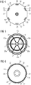
Fig. 4 shows a top view of the lubricant container ofFig. 1 , -
Fig. 5 shows a bottom view of a cap of the lubricant container ofFig. 1 , -
Fig. 6 shows a top view of a housing of the lubricant container ofFig. 1 , -
Fig. 7 shows a further longitudinal sectional view of the lubricant container ofFig. 1 , with a piston in an intermediate position along the housing of the lubricant container, -
Fig. 8 shows a magnified view of the detail VIII ofFig. 5 , -
Fig. 9 shows a top axonometric view of a cap for a lubricant container according to the present invention, -
Fig. 10 shows a top axonometric view of the cap ofFig. 9 , -
Fig. 11 shows a longitudinal sectional view of an adapter of the lubricant container ofFig. 1 . - The illustrations in the drawings are schematic. It is noted that in different figures, similar or identical elements are provided with the same reference signs.
- In the figures, a container 1 for collecting a lubricant comprises:
- a
housing 10 having a longitudinal axial extension along a longitudinal axis Y. The housing a first between a firstlongitudinal end 11 connectable to a source of lubricant, schematically represented inFigure 1 by a block with thereference sign 5, and a longitudinally oppositesecond end 12, - a
cap 13 attached to thesecond end 12, - a
piston 15 slidably movable inside thehousing 10 between thefirst end 11 and thesecond end 12 of thehousing 10, - an
adapter 16 having a firstrigid portion 46 connectable between thefirst end 11 of thehousing 10 and the source oflubricant 5. - According to a possible embodiment of the present invention, the lubricant is grease and the source of
lubricant 5 is a bearing using grease as lubricant. - The
cap 13 is attached to thesecond end 12 of thehousing 10 by means of a plurality ofsnap connections 20 for blocking the axial translation between thecap 13 and thehousing 10. Thecap 13 and thehousing 10 are respectively provided with a plurality of firstflat surface 21 and a plurality of secondflat surfaces 22 contacting each other for preventing the rotation of thecap 13 around a longitudinal axis Y of thehousing 10. The combined action of eachsnap connection 20 and of the coupling between each firstflat surface 21 and the corresponding secondflat surfaces 22 fixes thecap 13 to thehousing 10. - The plurality of first
flat surface 21 and aportion 20a of thesnap connection 20 can be directly provided on thecap 13, when thecap 13 is manufactured, for example by injection moulding. - The
cap 13 has apolygonal border 14 with a plurality ofborder walls 30, 31 (twelveborder walls polygonal border 14 comprises a first plurality of border walls 30 (sixborder walls 30 of the first plurality, in the embodiment of the attached figures) and a second plurality of border walls 31 (sixborder walls 31 of the second plurality, in the embodiment of the attached figures). The first plurality ofborder walls 30 and the second plurality ofborder walls 31 are interposed between one another with respect to the longitudinal axis Y, eachborder walls 30 of the first plurality being interposed between twoborder walls 31 of the second plurality and vice versa. Each of the first plurality ofborder walls 30 comprises afirst portion 20a of arespective snap connection 20. Thefirst portion 20a of thesnap connection 20 is created on thecap 13, for example through the same manufacturing process of injection moulding used for manufacturing thecap 13, and includes at least fourfaces 23a,b,c,d for providing four respective blocks (up, down, clockwise rotation and counter clockwise rotation) to the coupling between the cap and thehousing 10. - Each of the second plurality of
border walls 31 comprises an inner (with respect to the longitudinal axis Y) firstflat surface 21, which is subject to contact a respective secondflat surface 22 provided on thefirst end 11 of thehousing 10 for preventing both the clockwise and counter clockwise relative rotation of thecap 13 with respect to thehousing 10, around the longitudinal axis Y. - The plurality of first
flat surfaces 21 are also created on thecap 13, for example through the same manufacturing process of injection moulding used for manufacturing thecap 13. Thehousing 10 comprises a firstcylindrical portion 41 where thepiston 15 slidably moves and which include a free end corresponding to thesecond end 12 of thehousing 10. - The
second end 12 of thehousing 10 has a shape which permits engaging with thecap 13. To this purpose, thesecond end 12 has an external polygonal surface with a plurality ofsurfaces 24, 22 (twelvesurfaces second end 12 of thehousing 10 comprises a first plurality of circular surfaces 24 (sixcircular surfaces 24, in the embodiment of the attached figures) and a second plurality of flat surfaces 22 (sixflat surfaces 22, in the embodiment of the attached figures). - The first plurality of
circular surfaces 24 and the second plurality offlat surfaces 22 are interposed between one another around the longitudinal axis Y, eachcircular surface 24 being interposed between twoflat surfaces 22 and vice versa. Each of thecircular surfaces 24 comprises asecond portion 20b of arespective snap connection 20. Thesecond portion 20b of thesnap connection 20 is shaped as a tongue insertable in the first portion of thesnap connection 20 for engaging the fourfaces 23a,b,c,d , thus providing four respective blocks (up, down, clockwise rotation and counter clockwise rotation) to the coupling between the cap and thehousing 10. - The coupling between the
cap 13 and thehousing 10 is obtained by pushing axially, along the longitudinal axis Y, thecap 13 towards the first end of thehousing 10, thus bringing into engagement eachfirst portion 20a of thesnap connections 20 with a respectivesecond portion 20b of thesnap connections 20 a bringing into contact each firstflat surface 21 with a respective secondflat surface 22. - The
housing 10 further comprises a secondconic portion 42 interposed between the firstcylindrical portion 41 and thefirst end 11. Thefirst end 11 is cylindrical like the firstcylindrical portion 41, but has a smaller diameter than the firstcylindrical portion 41. Therefore the secondconic portion 42 is required to connect the firstcylindrical portion 41 and thefirst end 11. The firstcylindrical portion 41, the secondconic portion 42 and thefirst end 11 have in common the same longitudinal axis Y. Thefirst end 11 is provided with anexternal thread 45. - The
adapter 16 comprises a firstrigid portion 46 connectable between thefirst end 11 of thehousing 10 and the source oflubricant 5 and a seconddeformable portion 47 subject to contact the secondconic portion 42 of thehousing 10 for providing a sealing between thehousing 10 and theadapter 16. - According to a possible embodiment of the present invention, the first
rigid portion 46 is made of steel and the seconddeformable portion 47 is made of plastic material. - The first
rigid portion 46 comprises aninner thread 48 for connecting to theexternal thread 45 of thefirst end 11 of thehousing 10 and anexternal thread 48 for connecting to the source oflubricant 5, through a threaded duct (not shown in the attached figures). - The second
deformable portion 47 of theadapter 16 is conical in shape, thus permitting to receive the secondconic portion 42 of thehousing 10. The seconddeformable portion 47 is deformable between a first configuration (shown infigure 11 ) in which the seconddeformable portion 47 does not contact the secondconic portion 42 of the housing 10 (i.e. theadapter 16 and the housing are detached from each other) and a second configuration in which the seconddeformable portion 47 contact the secondconic portion 42 of the housing 10 (i.e. theadapter 16 and the housing are attached to each other). The opening angle β of the seconddeformable portion 47 in the second configuration is greater than the opening angle α in the first configuration. The deformation of the seconddeformable portion 47 of theadapter 16 when receiving thehousing 10 provides an optimal sealing between housing andadapter 16, permitting to collect spills of lubricant from thehousing 10 in theadapter 16. - The
piston 15 is made of a plastic material and comprises a circumferential surface 50 having a first deformablecircumferential lip 51 extending towards thefirst end 11 of thehousing 10 and a second deformablecircumferential lip 52 extending towards thesecond end 12 of thehousing 10. The deformablecircumferential lip piston 15. - The first and the second
circumferential lips cylindrical portion 41 of thehousing 10, for providing a convenient sealing between thepiston 15 and thehousing 10. - In operation, lubricant enters the
container 10 through thefirst end 11 and pushes thepiston 15 towards thesecond end 12, up to when thepiston 15 contacts thecap 13, i.e. the container 1 is full of lubricant. For permitting the sliding of thepiston 15 thecap 13 comprises avent hole 18, coaxial with the longitudinal axis Y of thehousing 10. For permitting easy empting operations of thecontainer 10 thevent hole 18 comprising a guide 19 for an external tool (not shown). The tool is insertable and guidable in the guide 19 of thevent hole 18 for pushing thepiston 15 from thesecond end 12 to thefirst end 11 of thehousing 10, thus forcing the lubricant to exit thehousing 10 through thefirst end 11. For this purpose alongitudinal cavity 61 is provided on thepiston 15 for engaging with the external tool.
In particular, according to a possible embodiment of the present invention, the second deformable portion of the adapter is cylindrical in shape and its deformable between a first configuration in which the second deformable portion does not contact the second conic portion of the housing and a second configuration in which the second deformable portion contact the second conic portion of the housing, the opening angle of the second deformable portion being greater in said second configuration than in said first configuration. Advantageously, the shape of the second deformable portion permits to achieve an effective sealing between the housing and the adapter.
Claims (10)
- A container (1) for collecting a lubricant, the container (1) comprising:- a housing (10) having a longitudinal axial extension between a first end (11) connectable to a source of lubricant (5) and a longitudinally opposite second end (12),- a cap (13) attached to the second end (12),- a piston (15) slidably movable inside the housing between the first end (11) and the second end (12) of the housing (10),wherein the cap (13) is attached to the second end (12) of the housing (10) by means of a snap connection (20) for blocking the axial translation between the cap (13) and the housing (10), the cap (13) and the housing (10) having respectively a first flat surface (21) and a second flat surface (22) contacting each other for preventing rotation of the cap (13) around a longitudinal axis (Y) of the housing (10).
- The container (1) according to claim 1, wherein the cap (13) has a polygonal border (14) with a plurality of border walls (30, 31), said snap connection (20) and said first flat surface (21) being provided on at least a wall (30, 31) of the polygonal border (14).
- The container (1) according to claim 2, wherein the cap (13) comprises a plurality of snap connections (20) and a plurality of first flat surfaces (21), the polygonal border (14) comprising a first plurality of border walls (30) and a second plurality of border walls (31), the plurality of snap connections (20) and the plurality of first flat surfaces (21) being respectively provided on the first plurality of border walls (30) and on the second plurality of border walls (31).
- The container (1) according to claim 3, wherein the first plurality of border walls (30) and the second plurality of border walls (31) are interposed between one another, each border walls (30) of the first plurality comprising a snap connection (20) and being interposed between two border walls (31) of the second plurality of border walls (31).
- The container (1) according to any of the preceding claims, wherein the cap (13) comprises a vent hole (18), said vent hole (18) comprising a guide (19) for an external tool, the tool being insertable and guidable in the vent hole (18) for pushing the piston (15) from the second end (12) to the first end (11) of the housing (10).
- The container (1) according to claim 5, wherein the vent hole (18) is coaxial with the longitudinal axis (Y) of the housing (10).
- The container (1) according to any of the preceding claims, wherein the housing (10) comprises a first cylindrical portion (41) where the piston (15) slidably moves and a second conic portion (42) interposed between the first cylindrical portion (41) and the first end (11), and wherein the container (1) further includes an adapter (16) having:- a first rigid portion (46) connectable between the first end (11) of the housing (10) and the source of lubricant (5), and- a second deformable portion (47) subject to contact the second conic portion (42) of the housing (10) for providing a sealing between the housing (10) and the adapter (16).
- The container (1) according to claim 7, wherein the second deformable portion (47) of the adapter (16) is cylindrical in shape and is deformable between a first configuration in which the second deformable portion (47) does not contact the second conic portion (42) of the housing (10) and a second configuration in which the second deformable portion (47) contact the second conic portion (42) of the housing (10), the opening angle of the second deformable portion (47) being greater in said second configuration than in said first configuration.
- The container (1) according to claim 7 or 8, wherein the first rigid portion (46) comprises an inner thread for connecting to the first end (11) of the housing (48) and an external thread (49) for connecting to the source of lubricant (5).
- The container (1) according to any of the preceding claims, wherein the piston (15) comprises a circumferential surface (50) having a first deformable circumferential lip (51) extending towards the first end (11) of the housing and a second deformable circumferential lip (52) extending towards the second end (12) of the housing (10), the first and the second circumferential lips (51, 52) being deformable for providing a sealing between the piston (15) and the housing (10).
Applications Claiming Priority (1)
| Application Number | Priority Date | Filing Date | Title |
|---|---|---|---|
| DE102016220407 | 2016-10-18 |
Publications (3)
| Publication Number | Publication Date |
|---|---|
| EP3312493A2 true EP3312493A2 (en) | 2018-04-25 |
| EP3312493A3 EP3312493A3 (en) | 2018-07-18 |
| EP3312493B1 EP3312493B1 (en) | 2020-01-29 |
Family
ID=59337494
Family Applications (1)
| Application Number | Title | Priority Date | Filing Date |
|---|---|---|---|
| EP17180866.0A Active EP3312493B1 (en) | 2016-10-18 | 2017-07-12 | Lubricant container |
Country Status (4)
| Country | Link |
|---|---|
| US (1) | US10408381B2 (en) |
| EP (1) | EP3312493B1 (en) |
| CN (1) | CN107956993B (en) |
| DK (1) | DK3312493T3 (en) |
Cited By (1)
| Publication number | Priority date | Publication date | Assignee | Title |
|---|---|---|---|---|
| US12038131B2 (en) | 2020-04-27 | 2024-07-16 | Siemens Gamesa Renewable Energy A/S | Grease collection arrangement |
Citations (1)
| Publication number | Priority date | Publication date | Assignee | Title |
|---|---|---|---|---|
| EP2573444A1 (en) | 2011-09-20 | 2013-03-27 | Perma-Tec GmbH & Co. KG | Collection container for lubricants |
Family Cites Families (24)
| Publication number | Priority date | Publication date | Assignee | Title |
|---|---|---|---|---|
| US612075A (en) * | 1898-10-11 | Lubricating device | ||
| US822895A (en) * | 1906-02-14 | 1906-06-05 | Frederick Henkelman | Closure for bottles, jars, &c. |
| US1333245A (en) * | 1919-06-18 | 1920-03-09 | Edwin F Carson | Milk-bottle and cap |
| US1373437A (en) | 1919-08-21 | 1921-04-05 | Lougheed Victor | Lid or closure for receptacles |
| US1562073A (en) * | 1924-09-16 | 1925-11-17 | Albert J Sterling | Method of and means for effecting closures |
| US4735288A (en) * | 1986-01-24 | 1988-04-05 | Ckd Kabushiki Kaisha | Detachably attaching mechanism for cup of lubricator or filter used with air-actuated device |
| FR2609970B1 (en) * | 1987-01-23 | 1990-02-23 | Moulage Specialise Pack Atel | DEVICE FOR CLOSING A NECK CONTAINER WITH ELASTICALLY DEFORMABLE POSITIONING ELEMENTS |
| AU606173B2 (en) * | 1987-06-18 | 1991-01-31 | Sl Lube/Systems, Inc. | Disposable lubricating system |
| US5050762A (en) * | 1990-03-30 | 1991-09-24 | Dusaline Giorgi | Trash container |
| DE4242938A1 (en) * | 1992-12-18 | 1994-06-23 | Richter Berthold | Dispenser with spring reservoir drive |
| US5579933A (en) * | 1993-06-30 | 1996-12-03 | Magenta Corporation | Safety container and dispenser for small items |
| DE10207204A1 (en) * | 2001-04-05 | 2002-12-12 | Alpla Werke | Combination of a bottle with a snap-on adapter and / or a cap |
| US7731050B2 (en) | 2003-06-10 | 2010-06-08 | Efficient Container Company | Container and closure combination including spreading and lifting cams |
| AU2005240682B2 (en) | 2004-05-06 | 2010-11-25 | Stephania Holdings Inc. | Automatic motor driven in-line piston pump lubricator |
| DE202006017522U1 (en) | 2006-11-15 | 2007-01-18 | Perma-Tec Gmbh & Co. Kg | Lubricant dispenser has at least one tooth arranged on periphery of piston and pressing against inside wall of lubricant reservoir, and consists of harder material in comparison to lubricant reservoir |
| DE102007037422A1 (en) | 2007-08-08 | 2009-02-19 | Perma-Tec Gmbh & Co. Kg | lubricant dispenser |
| DE102008017098A1 (en) * | 2008-04-02 | 2009-10-08 | Perma-Tec Gmbh & Co. Kg | Use of grease filled tin in lubricant dispenser for grease lubrication of anti-friction bearing, using operating head for generation of pressure, and outlet piece fixed at bottom of tin, where hollow pin is pierced through bottom of tin |
| DE102009022707B4 (en) * | 2009-03-05 | 2014-03-27 | Perma-Tec Gmbh & Co. Kg | lubricant dispenser |
| WO2011062211A1 (en) * | 2009-11-20 | 2011-05-26 | 吉田プラ工業株式会社 | Container with cap |
| US8298308B2 (en) * | 2010-03-15 | 2012-10-30 | GM Global Technology Operations LLC | Air filter assembly |
| DE202010014823U1 (en) | 2010-11-01 | 2011-01-05 | Lincoln Gmbh | Sump for lubricant and bearing assembly hereby |
| US9108776B2 (en) * | 2012-03-09 | 2015-08-18 | Wki Holding Company, Inc. | Lid, and container system and lid |
| JP5957764B2 (en) * | 2012-11-21 | 2016-07-27 | 加藤 卓也 | Cap and container provided with the cap |
| ES2647630T3 (en) * | 2012-12-13 | 2017-12-22 | Guala Closures S.P.A. | Union system of two tubular members and liquid container equipped with said union system |
-
2017
- 2017-07-12 DK DK17180866.0T patent/DK3312493T3/en active
- 2017-07-12 EP EP17180866.0A patent/EP3312493B1/en active Active
- 2017-07-18 US US15/652,608 patent/US10408381B2/en active Active
- 2017-10-18 CN CN201710970867.3A patent/CN107956993B/en not_active Expired - Fee Related
Patent Citations (1)
| Publication number | Priority date | Publication date | Assignee | Title |
|---|---|---|---|---|
| EP2573444A1 (en) | 2011-09-20 | 2013-03-27 | Perma-Tec GmbH & Co. KG | Collection container for lubricants |
Cited By (1)
| Publication number | Priority date | Publication date | Assignee | Title |
|---|---|---|---|---|
| US12038131B2 (en) | 2020-04-27 | 2024-07-16 | Siemens Gamesa Renewable Energy A/S | Grease collection arrangement |
Also Published As
| Publication number | Publication date |
|---|---|
| EP3312493B1 (en) | 2020-01-29 |
| US10408381B2 (en) | 2019-09-10 |
| EP3312493A3 (en) | 2018-07-18 |
| US20180106426A1 (en) | 2018-04-19 |
| CN107956993A (en) | 2018-04-24 |
| CN107956993B (en) | 2020-03-24 |
| DK3312493T3 (en) | 2020-04-14 |
Similar Documents
| Publication | Publication Date | Title |
|---|---|---|
| US6627160B2 (en) | Multiple channel pipetting device | |
| US8512650B2 (en) | Device for mounting pipette tips, pipette tip, and pipetting device | |
| US5171025A (en) | Sealing arrangement for a valve and more particularly one in the form of a multi-way valve | |
| EP2700450B1 (en) | Sealed pipette | |
| US9772058B2 (en) | Sealed-coupling device without a retention area | |
| CN105102145B (en) | Stamping equipment | |
| US418906A (en) | Hose-coupling | |
| KR100989763B1 (en) | Cable Protection Guide | |
| EP3312493B1 (en) | Lubricant container | |
| CN102466122A (en) | Collecting container for lubricant and bearing device with collecting container | |
| EP2937675A1 (en) | Oil level gauge device | |
| DE102018000963A1 (en) | Drive comprising an electric motor and a transmission | |
| EP3636350B1 (en) | Sealant discharging apparatus | |
| KR960006183B1 (en) | Hydraulic piping connection | |
| KR100984839B1 (en) | Object for connecting pipes | |
| EP1743745A1 (en) | Industrial robot | |
| GB2024961A (en) | Lubricating tie rods | |
| US20190329239A1 (en) | Pipetting system tip having double conicity | |
| KR101889741B1 (en) | Applicator that allows easy mounting and removal of cartridge | |
| KR102047995B1 (en) | Hole masking apparatus | |
| US20130036852A1 (en) | Operation unit | |
| CN211073285U (en) | Positioning device | |
| US11111041B2 (en) | Tube holder for a tube filling machine | |
| KR101854837B1 (en) | Sump tank | |
| CN213176251U (en) | Crane oil cylinder guide sleeve convenient to butt joint |
Legal Events
| Date | Code | Title | Description |
|---|---|---|---|
| PUAI | Public reference made under article 153(3) epc to a published international application that has entered the european phase |
Free format text: ORIGINAL CODE: 0009012 |
|
| STAA | Information on the status of an ep patent application or granted ep patent |
Free format text: STATUS: THE APPLICATION HAS BEEN PUBLISHED |
|
| AK | Designated contracting states |
Kind code of ref document: A2 Designated state(s): AL AT BE BG CH CY CZ DE DK EE ES FI FR GB GR HR HU IE IS IT LI LT LU LV MC MK MT NL NO PL PT RO RS SE SI SK SM TR |
|
| AX | Request for extension of the european patent |
Extension state: BA ME |
|
| PUAL | Search report despatched |
Free format text: ORIGINAL CODE: 0009013 |
|
| AK | Designated contracting states |
Kind code of ref document: A3 Designated state(s): AL AT BE BG CH CY CZ DE DK EE ES FI FR GB GR HR HU IE IS IT LI LT LU LV MC MK MT NL NO PL PT RO RS SE SI SK SM TR |
|
| AX | Request for extension of the european patent |
Extension state: BA ME |
|
| RIC1 | Information provided on ipc code assigned before grant |
Ipc: F16N 11/08 20060101AFI20180608BHEP Ipc: B65D 41/16 20060101ALI20180608BHEP |
|
| STAA | Information on the status of an ep patent application or granted ep patent |
Free format text: STATUS: REQUEST FOR EXAMINATION WAS MADE |
|
| 17P | Request for examination filed |
Effective date: 20190104 |
|
| RBV | Designated contracting states (corrected) |
Designated state(s): AL AT BE BG CH CY CZ DE DK EE ES FI FR GB GR HR HU IE IS IT LI LT LU LV MC MK MT NL NO PL PT RO RS SE SI SK SM TR |
|
| RAP1 | Party data changed (applicant data changed or rights of an application transferred) |
Owner name: SIEMENS GAMESA RENEWABLE ENERGY A/S |
|
| GRAP | Despatch of communication of intention to grant a patent |
Free format text: ORIGINAL CODE: EPIDOSNIGR1 |
|
| STAA | Information on the status of an ep patent application or granted ep patent |
Free format text: STATUS: GRANT OF PATENT IS INTENDED |
|
| INTG | Intention to grant announced |
Effective date: 20190916 |
|
| GRAS | Grant fee paid |
Free format text: ORIGINAL CODE: EPIDOSNIGR3 |
|
| GRAA | (expected) grant |
Free format text: ORIGINAL CODE: 0009210 |
|
| STAA | Information on the status of an ep patent application or granted ep patent |
Free format text: STATUS: THE PATENT HAS BEEN GRANTED |
|
| AK | Designated contracting states |
Kind code of ref document: B1 Designated state(s): AL AT BE BG CH CY CZ DE DK EE ES FI FR GB GR HR HU IE IS IT LI LT LU LV MC MK MT NL NO PL PT RO RS SE SI SK SM TR |
|
| REG | Reference to a national code |
Ref country code: GB Ref legal event code: FG4D |
|
| REG | Reference to a national code |
Ref country code: CH Ref legal event code: EP |
|
| REG | Reference to a national code |
Ref country code: AT Ref legal event code: REF Ref document number: 1228749 Country of ref document: AT Kind code of ref document: T Effective date: 20200215 |
|
| REG | Reference to a national code |
Ref country code: IE Ref legal event code: FG4D |
|
| REG | Reference to a national code |
Ref country code: DE Ref legal event code: R096 Ref document number: 602017011101 Country of ref document: DE |
|
| REG | Reference to a national code |
Ref country code: DK Ref legal event code: T3 Effective date: 20200410 |
|
| REG | Reference to a national code |
Ref country code: NL Ref legal event code: MP Effective date: 20200129 |
|
| PG25 | Lapsed in a contracting state [announced via postgrant information from national office to epo] |
Ref country code: FI Free format text: LAPSE BECAUSE OF FAILURE TO SUBMIT A TRANSLATION OF THE DESCRIPTION OR TO PAY THE FEE WITHIN THE PRESCRIBED TIME-LIMIT Effective date: 20200129 Ref country code: NO Free format text: LAPSE BECAUSE OF FAILURE TO SUBMIT A TRANSLATION OF THE DESCRIPTION OR TO PAY THE FEE WITHIN THE PRESCRIBED TIME-LIMIT Effective date: 20200429 Ref country code: RS Free format text: LAPSE BECAUSE OF FAILURE TO SUBMIT A TRANSLATION OF THE DESCRIPTION OR TO PAY THE FEE WITHIN THE PRESCRIBED TIME-LIMIT Effective date: 20200129 Ref country code: PT Free format text: LAPSE BECAUSE OF FAILURE TO SUBMIT A TRANSLATION OF THE DESCRIPTION OR TO PAY THE FEE WITHIN THE PRESCRIBED TIME-LIMIT Effective date: 20200621 |
|
| REG | Reference to a national code |
Ref country code: LT Ref legal event code: MG4D |
|
| PG25 | Lapsed in a contracting state [announced via postgrant information from national office to epo] |
Ref country code: IS Free format text: LAPSE BECAUSE OF FAILURE TO SUBMIT A TRANSLATION OF THE DESCRIPTION OR TO PAY THE FEE WITHIN THE PRESCRIBED TIME-LIMIT Effective date: 20200529 Ref country code: SE Free format text: LAPSE BECAUSE OF FAILURE TO SUBMIT A TRANSLATION OF THE DESCRIPTION OR TO PAY THE FEE WITHIN THE PRESCRIBED TIME-LIMIT Effective date: 20200129 Ref country code: BG Free format text: LAPSE BECAUSE OF FAILURE TO SUBMIT A TRANSLATION OF THE DESCRIPTION OR TO PAY THE FEE WITHIN THE PRESCRIBED TIME-LIMIT Effective date: 20200429 Ref country code: GR Free format text: LAPSE BECAUSE OF FAILURE TO SUBMIT A TRANSLATION OF THE DESCRIPTION OR TO PAY THE FEE WITHIN THE PRESCRIBED TIME-LIMIT Effective date: 20200430 Ref country code: LV Free format text: LAPSE BECAUSE OF FAILURE TO SUBMIT A TRANSLATION OF THE DESCRIPTION OR TO PAY THE FEE WITHIN THE PRESCRIBED TIME-LIMIT Effective date: 20200129 Ref country code: HR Free format text: LAPSE BECAUSE OF FAILURE TO SUBMIT A TRANSLATION OF THE DESCRIPTION OR TO PAY THE FEE WITHIN THE PRESCRIBED TIME-LIMIT Effective date: 20200129 |
|
| PG25 | Lapsed in a contracting state [announced via postgrant information from national office to epo] |
Ref country code: NL Free format text: LAPSE BECAUSE OF FAILURE TO SUBMIT A TRANSLATION OF THE DESCRIPTION OR TO PAY THE FEE WITHIN THE PRESCRIBED TIME-LIMIT Effective date: 20200129 |
|
| PG25 | Lapsed in a contracting state [announced via postgrant information from national office to epo] |
Ref country code: ES Free format text: LAPSE BECAUSE OF FAILURE TO SUBMIT A TRANSLATION OF THE DESCRIPTION OR TO PAY THE FEE WITHIN THE PRESCRIBED TIME-LIMIT Effective date: 20200129 Ref country code: SK Free format text: LAPSE BECAUSE OF FAILURE TO SUBMIT A TRANSLATION OF THE DESCRIPTION OR TO PAY THE FEE WITHIN THE PRESCRIBED TIME-LIMIT Effective date: 20200129 Ref country code: EE Free format text: LAPSE BECAUSE OF FAILURE TO SUBMIT A TRANSLATION OF THE DESCRIPTION OR TO PAY THE FEE WITHIN THE PRESCRIBED TIME-LIMIT Effective date: 20200129 Ref country code: SM Free format text: LAPSE BECAUSE OF FAILURE TO SUBMIT A TRANSLATION OF THE DESCRIPTION OR TO PAY THE FEE WITHIN THE PRESCRIBED TIME-LIMIT Effective date: 20200129 Ref country code: LT Free format text: LAPSE BECAUSE OF FAILURE TO SUBMIT A TRANSLATION OF THE DESCRIPTION OR TO PAY THE FEE WITHIN THE PRESCRIBED TIME-LIMIT Effective date: 20200129 Ref country code: RO Free format text: LAPSE BECAUSE OF FAILURE TO SUBMIT A TRANSLATION OF THE DESCRIPTION OR TO PAY THE FEE WITHIN THE PRESCRIBED TIME-LIMIT Effective date: 20200129 Ref country code: CZ Free format text: LAPSE BECAUSE OF FAILURE TO SUBMIT A TRANSLATION OF THE DESCRIPTION OR TO PAY THE FEE WITHIN THE PRESCRIBED TIME-LIMIT Effective date: 20200129 |
|
| REG | Reference to a national code |
Ref country code: DE Ref legal event code: R097 Ref document number: 602017011101 Country of ref document: DE |
|
| REG | Reference to a national code |
Ref country code: AT Ref legal event code: MK05 Ref document number: 1228749 Country of ref document: AT Kind code of ref document: T Effective date: 20200129 |
|
| PLBE | No opposition filed within time limit |
Free format text: ORIGINAL CODE: 0009261 |
|
| STAA | Information on the status of an ep patent application or granted ep patent |
Free format text: STATUS: NO OPPOSITION FILED WITHIN TIME LIMIT |
|
| 26N | No opposition filed |
Effective date: 20201030 |
|
| PG25 | Lapsed in a contracting state [announced via postgrant information from national office to epo] |
Ref country code: AT Free format text: LAPSE BECAUSE OF FAILURE TO SUBMIT A TRANSLATION OF THE DESCRIPTION OR TO PAY THE FEE WITHIN THE PRESCRIBED TIME-LIMIT Effective date: 20200129 Ref country code: IT Free format text: LAPSE BECAUSE OF FAILURE TO SUBMIT A TRANSLATION OF THE DESCRIPTION OR TO PAY THE FEE WITHIN THE PRESCRIBED TIME-LIMIT Effective date: 20200129 |
|
| PG25 | Lapsed in a contracting state [announced via postgrant information from national office to epo] |
Ref country code: PL Free format text: LAPSE BECAUSE OF FAILURE TO SUBMIT A TRANSLATION OF THE DESCRIPTION OR TO PAY THE FEE WITHIN THE PRESCRIBED TIME-LIMIT Effective date: 20200129 Ref country code: SI Free format text: LAPSE BECAUSE OF FAILURE TO SUBMIT A TRANSLATION OF THE DESCRIPTION OR TO PAY THE FEE WITHIN THE PRESCRIBED TIME-LIMIT Effective date: 20200129 Ref country code: MC Free format text: LAPSE BECAUSE OF FAILURE TO SUBMIT A TRANSLATION OF THE DESCRIPTION OR TO PAY THE FEE WITHIN THE PRESCRIBED TIME-LIMIT Effective date: 20200129 |
|
| REG | Reference to a national code |
Ref country code: CH Ref legal event code: PL |
|
| REG | Reference to a national code |
Ref country code: BE Ref legal event code: MM Effective date: 20200731 |
|
| PG25 | Lapsed in a contracting state [announced via postgrant information from national office to epo] |
Ref country code: CH Free format text: LAPSE BECAUSE OF NON-PAYMENT OF DUE FEES Effective date: 20200731 Ref country code: LI Free format text: LAPSE BECAUSE OF NON-PAYMENT OF DUE FEES Effective date: 20200731 Ref country code: LU Free format text: LAPSE BECAUSE OF NON-PAYMENT OF DUE FEES Effective date: 20200712 Ref country code: FR Free format text: LAPSE BECAUSE OF NON-PAYMENT OF DUE FEES Effective date: 20200731 |
|
| PG25 | Lapsed in a contracting state [announced via postgrant information from national office to epo] |
Ref country code: BE Free format text: LAPSE BECAUSE OF NON-PAYMENT OF DUE FEES Effective date: 20200731 |
|
| PG25 | Lapsed in a contracting state [announced via postgrant information from national office to epo] |
Ref country code: IE Free format text: LAPSE BECAUSE OF NON-PAYMENT OF DUE FEES Effective date: 20200712 |
|
| PG25 | Lapsed in a contracting state [announced via postgrant information from national office to epo] |
Ref country code: TR Free format text: LAPSE BECAUSE OF FAILURE TO SUBMIT A TRANSLATION OF THE DESCRIPTION OR TO PAY THE FEE WITHIN THE PRESCRIBED TIME-LIMIT Effective date: 20200129 Ref country code: MT Free format text: LAPSE BECAUSE OF FAILURE TO SUBMIT A TRANSLATION OF THE DESCRIPTION OR TO PAY THE FEE WITHIN THE PRESCRIBED TIME-LIMIT Effective date: 20200129 Ref country code: CY Free format text: LAPSE BECAUSE OF FAILURE TO SUBMIT A TRANSLATION OF THE DESCRIPTION OR TO PAY THE FEE WITHIN THE PRESCRIBED TIME-LIMIT Effective date: 20200129 |
|
| PG25 | Lapsed in a contracting state [announced via postgrant information from national office to epo] |
Ref country code: MK Free format text: LAPSE BECAUSE OF FAILURE TO SUBMIT A TRANSLATION OF THE DESCRIPTION OR TO PAY THE FEE WITHIN THE PRESCRIBED TIME-LIMIT Effective date: 20200129 Ref country code: AL Free format text: LAPSE BECAUSE OF FAILURE TO SUBMIT A TRANSLATION OF THE DESCRIPTION OR TO PAY THE FEE WITHIN THE PRESCRIBED TIME-LIMIT Effective date: 20200129 |
|
| REG | Reference to a national code |
Ref country code: DE Ref legal event code: R082 Ref document number: 602017011101 Country of ref document: DE Representative=s name: SAUTHOFF, KARSTEN, DIPL.-ING. UNIV., DE |
|
| PGFP | Annual fee paid to national office [announced via postgrant information from national office to epo] |
Ref country code: GB Payment date: 20230724 Year of fee payment: 7 |
|
| PGFP | Annual fee paid to national office [announced via postgrant information from national office to epo] |
Ref country code: DK Payment date: 20230724 Year of fee payment: 7 Ref country code: DE Payment date: 20230720 Year of fee payment: 7 |
|
| REG | Reference to a national code |
Ref country code: DE Ref legal event code: R119 Ref document number: 602017011101 Country of ref document: DE |
|
| REG | Reference to a national code |
Ref country code: DK Ref legal event code: EBP Effective date: 20240731 |
|
| GBPC | Gb: european patent ceased through non-payment of renewal fee |
Effective date: 20240712 |
|
| PG25 | Lapsed in a contracting state [announced via postgrant information from national office to epo] |
Ref country code: DE Free format text: LAPSE BECAUSE OF NON-PAYMENT OF DUE FEES Effective date: 20250201 |
|
| PG25 | Lapsed in a contracting state [announced via postgrant information from national office to epo] |
Ref country code: GB Free format text: LAPSE BECAUSE OF NON-PAYMENT OF DUE FEES Effective date: 20240712 |
|
| PG25 | Lapsed in a contracting state [announced via postgrant information from national office to epo] |
Ref country code: DK Free format text: LAPSE BECAUSE OF NON-PAYMENT OF DUE FEES Effective date: 20240731 |