EP3312441A1 - Panel fastening system - Google Patents
Panel fastening system Download PDFInfo
- Publication number
- EP3312441A1 EP3312441A1 EP17194603.1A EP17194603A EP3312441A1 EP 3312441 A1 EP3312441 A1 EP 3312441A1 EP 17194603 A EP17194603 A EP 17194603A EP 3312441 A1 EP3312441 A1 EP 3312441A1
- Authority
- EP
- European Patent Office
- Prior art keywords
- stud
- cam
- panel
- case
- hole
- Prior art date
- Legal status (The legal status is an assumption and is not a legal conclusion. Google has not performed a legal analysis and makes no representation as to the accuracy of the status listed.)
- Granted
Links
Images






Classifications
-
- F—MECHANICAL ENGINEERING; LIGHTING; HEATING; WEAPONS; BLASTING
- F16—ENGINEERING ELEMENTS AND UNITS; GENERAL MEASURES FOR PRODUCING AND MAINTAINING EFFECTIVE FUNCTIONING OF MACHINES OR INSTALLATIONS; THERMAL INSULATION IN GENERAL
- F16B—DEVICES FOR FASTENING OR SECURING CONSTRUCTIONAL ELEMENTS OR MACHINE PARTS TOGETHER, e.g. NAILS, BOLTS, CIRCLIPS, CLAMPS, CLIPS OR WEDGES; JOINTS OR JOINTING
- F16B12/00—Jointing of furniture or the like, e.g. hidden from exterior
- F16B12/10—Jointing of furniture or the like, e.g. hidden from exterior using pegs, bolts, tenons, clamps, clips, or the like
- F16B12/12—Jointing of furniture or the like, e.g. hidden from exterior using pegs, bolts, tenons, clamps, clips, or the like for non-metal furniture parts, e.g. made of wood, of plastics
- F16B12/14—Jointing of furniture or the like, e.g. hidden from exterior using pegs, bolts, tenons, clamps, clips, or the like for non-metal furniture parts, e.g. made of wood, of plastics using threaded bolts or screws
-
- F—MECHANICAL ENGINEERING; LIGHTING; HEATING; WEAPONS; BLASTING
- F16—ENGINEERING ELEMENTS AND UNITS; GENERAL MEASURES FOR PRODUCING AND MAINTAINING EFFECTIVE FUNCTIONING OF MACHINES OR INSTALLATIONS; THERMAL INSULATION IN GENERAL
- F16B—DEVICES FOR FASTENING OR SECURING CONSTRUCTIONAL ELEMENTS OR MACHINE PARTS TOGETHER, e.g. NAILS, BOLTS, CIRCLIPS, CLAMPS, CLIPS OR WEDGES; JOINTS OR JOINTING
- F16B5/00—Joining sheets or plates, e.g. panels, to one another or to strips or bars parallel to them
- F16B5/02—Joining sheets or plates, e.g. panels, to one another or to strips or bars parallel to them by means of fastening members using screw-thread
-
- F—MECHANICAL ENGINEERING; LIGHTING; HEATING; WEAPONS; BLASTING
- F16—ENGINEERING ELEMENTS AND UNITS; GENERAL MEASURES FOR PRODUCING AND MAINTAINING EFFECTIVE FUNCTIONING OF MACHINES OR INSTALLATIONS; THERMAL INSULATION IN GENERAL
- F16B—DEVICES FOR FASTENING OR SECURING CONSTRUCTIONAL ELEMENTS OR MACHINE PARTS TOGETHER, e.g. NAILS, BOLTS, CIRCLIPS, CLAMPS, CLIPS OR WEDGES; JOINTS OR JOINTING
- F16B5/00—Joining sheets or plates, e.g. panels, to one another or to strips or bars parallel to them
- F16B5/01—Joining sheets or plates, e.g. panels, to one another or to strips or bars parallel to them by means of fastening elements specially adapted for honeycomb panels
-
- B—PERFORMING OPERATIONS; TRANSPORTING
- B64—AIRCRAFT; AVIATION; COSMONAUTICS
- B64C—AEROPLANES; HELICOPTERS
- B64C1/00—Fuselages; Constructional features common to fuselages, wings, stabilising surfaces or the like
- B64C1/06—Frames; Stringers; Longerons ; Fuselage sections
- B64C1/068—Fuselage sections
- B64C1/069—Joining arrangements therefor
-
- B—PERFORMING OPERATIONS; TRANSPORTING
- B64—AIRCRAFT; AVIATION; COSMONAUTICS
- B64C—AEROPLANES; HELICOPTERS
- B64C1/00—Fuselages; Constructional features common to fuselages, wings, stabilising surfaces or the like
- B64C1/06—Frames; Stringers; Longerons ; Fuselage sections
- B64C1/12—Construction or attachment of skin panels
-
- B—PERFORMING OPERATIONS; TRANSPORTING
- B64—AIRCRAFT; AVIATION; COSMONAUTICS
- B64C—AEROPLANES; HELICOPTERS
- B64C3/00—Wings
- B64C3/26—Construction, shape, or attachment of separate skins, e.g. panels
-
- E—FIXED CONSTRUCTIONS
- E04—BUILDING
- E04C—STRUCTURAL ELEMENTS; BUILDING MATERIALS
- E04C2/00—Building elements of relatively thin form for the construction of parts of buildings, e.g. sheet materials, slabs, or panels
- E04C2/30—Building elements of relatively thin form for the construction of parts of buildings, e.g. sheet materials, slabs, or panels characterised by the shape or structure
-
- E—FIXED CONSTRUCTIONS
- E04—BUILDING
- E04C—STRUCTURAL ELEMENTS; BUILDING MATERIALS
- E04C2/00—Building elements of relatively thin form for the construction of parts of buildings, e.g. sheet materials, slabs, or panels
- E04C2/44—Building elements of relatively thin form for the construction of parts of buildings, e.g. sheet materials, slabs, or panels characterised by the purpose
-
- F—MECHANICAL ENGINEERING; LIGHTING; HEATING; WEAPONS; BLASTING
- F16—ENGINEERING ELEMENTS AND UNITS; GENERAL MEASURES FOR PRODUCING AND MAINTAINING EFFECTIVE FUNCTIONING OF MACHINES OR INSTALLATIONS; THERMAL INSULATION IN GENERAL
- F16B—DEVICES FOR FASTENING OR SECURING CONSTRUCTIONAL ELEMENTS OR MACHINE PARTS TOGETHER, e.g. NAILS, BOLTS, CIRCLIPS, CLAMPS, CLIPS OR WEDGES; JOINTS OR JOINTING
- F16B11/00—Connecting constructional elements or machine parts by sticking or pressing them together, e.g. cold pressure welding
- F16B11/006—Connecting constructional elements or machine parts by sticking or pressing them together, e.g. cold pressure welding by gluing
-
- F—MECHANICAL ENGINEERING; LIGHTING; HEATING; WEAPONS; BLASTING
- F16—ENGINEERING ELEMENTS AND UNITS; GENERAL MEASURES FOR PRODUCING AND MAINTAINING EFFECTIVE FUNCTIONING OF MACHINES OR INSTALLATIONS; THERMAL INSULATION IN GENERAL
- F16B—DEVICES FOR FASTENING OR SECURING CONSTRUCTIONAL ELEMENTS OR MACHINE PARTS TOGETHER, e.g. NAILS, BOLTS, CIRCLIPS, CLAMPS, CLIPS OR WEDGES; JOINTS OR JOINTING
- F16B12/00—Jointing of furniture or the like, e.g. hidden from exterior
- F16B12/10—Jointing of furniture or the like, e.g. hidden from exterior using pegs, bolts, tenons, clamps, clips, or the like
- F16B12/12—Jointing of furniture or the like, e.g. hidden from exterior using pegs, bolts, tenons, clamps, clips, or the like for non-metal furniture parts, e.g. made of wood, of plastics
- F16B12/20—Jointing of furniture or the like, e.g. hidden from exterior using pegs, bolts, tenons, clamps, clips, or the like for non-metal furniture parts, e.g. made of wood, of plastics using clamps, clips, wedges, sliding bolts, or the like
- F16B12/2009—Jointing of furniture or the like, e.g. hidden from exterior using pegs, bolts, tenons, clamps, clips, or the like for non-metal furniture parts, e.g. made of wood, of plastics using clamps, clips, wedges, sliding bolts, or the like actuated by rotary motion
-
- F—MECHANICAL ENGINEERING; LIGHTING; HEATING; WEAPONS; BLASTING
- F16—ENGINEERING ELEMENTS AND UNITS; GENERAL MEASURES FOR PRODUCING AND MAINTAINING EFFECTIVE FUNCTIONING OF MACHINES OR INSTALLATIONS; THERMAL INSULATION IN GENERAL
- F16B—DEVICES FOR FASTENING OR SECURING CONSTRUCTIONAL ELEMENTS OR MACHINE PARTS TOGETHER, e.g. NAILS, BOLTS, CIRCLIPS, CLAMPS, CLIPS OR WEDGES; JOINTS OR JOINTING
- F16B12/00—Jointing of furniture or the like, e.g. hidden from exterior
- F16B12/10—Jointing of furniture or the like, e.g. hidden from exterior using pegs, bolts, tenons, clamps, clips, or the like
- F16B12/12—Jointing of furniture or the like, e.g. hidden from exterior using pegs, bolts, tenons, clamps, clips, or the like for non-metal furniture parts, e.g. made of wood, of plastics
- F16B12/24—Jointing of furniture or the like, e.g. hidden from exterior using pegs, bolts, tenons, clamps, clips, or the like for non-metal furniture parts, e.g. made of wood, of plastics using separate pins, dowels, or the like
-
- F—MECHANICAL ENGINEERING; LIGHTING; HEATING; WEAPONS; BLASTING
- F16—ENGINEERING ELEMENTS AND UNITS; GENERAL MEASURES FOR PRODUCING AND MAINTAINING EFFECTIVE FUNCTIONING OF MACHINES OR INSTALLATIONS; THERMAL INSULATION IN GENERAL
- F16B—DEVICES FOR FASTENING OR SECURING CONSTRUCTIONAL ELEMENTS OR MACHINE PARTS TOGETHER, e.g. NAILS, BOLTS, CIRCLIPS, CLAMPS, CLIPS OR WEDGES; JOINTS OR JOINTING
- F16B37/00—Nuts or like thread-engaging members
- F16B37/04—Devices for fastening nuts to surfaces, e.g. sheets, plates
- F16B37/041—Releasable devices
- F16B37/042—Releasable devices locking by rotation
-
- F—MECHANICAL ENGINEERING; LIGHTING; HEATING; WEAPONS; BLASTING
- F16—ENGINEERING ELEMENTS AND UNITS; GENERAL MEASURES FOR PRODUCING AND MAINTAINING EFFECTIVE FUNCTIONING OF MACHINES OR INSTALLATIONS; THERMAL INSULATION IN GENERAL
- F16B—DEVICES FOR FASTENING OR SECURING CONSTRUCTIONAL ELEMENTS OR MACHINE PARTS TOGETHER, e.g. NAILS, BOLTS, CIRCLIPS, CLAMPS, CLIPS OR WEDGES; JOINTS OR JOINTING
- F16B12/00—Jointing of furniture or the like, e.g. hidden from exterior
- F16B12/44—Leg joints; Corner joints
- F16B12/46—Non-metal corner connections
-
- F—MECHANICAL ENGINEERING; LIGHTING; HEATING; WEAPONS; BLASTING
- F16—ENGINEERING ELEMENTS AND UNITS; GENERAL MEASURES FOR PRODUCING AND MAINTAINING EFFECTIVE FUNCTIONING OF MACHINES OR INSTALLATIONS; THERMAL INSULATION IN GENERAL
- F16B—DEVICES FOR FASTENING OR SECURING CONSTRUCTIONAL ELEMENTS OR MACHINE PARTS TOGETHER, e.g. NAILS, BOLTS, CIRCLIPS, CLAMPS, CLIPS OR WEDGES; JOINTS OR JOINTING
- F16B13/00—Dowels or other devices fastened in walls or the like by inserting them in holes made therein for that purpose
- F16B13/14—Non-metallic plugs or sleeves; Use of liquid, loose solid or kneadable material therefor
- F16B13/141—Fixing plugs in holes by the use of settable material
-
- F—MECHANICAL ENGINEERING; LIGHTING; HEATING; WEAPONS; BLASTING
- F16—ENGINEERING ELEMENTS AND UNITS; GENERAL MEASURES FOR PRODUCING AND MAINTAINING EFFECTIVE FUNCTIONING OF MACHINES OR INSTALLATIONS; THERMAL INSULATION IN GENERAL
- F16B—DEVICES FOR FASTENING OR SECURING CONSTRUCTIONAL ELEMENTS OR MACHINE PARTS TOGETHER, e.g. NAILS, BOLTS, CIRCLIPS, CLAMPS, CLIPS OR WEDGES; JOINTS OR JOINTING
- F16B12/00—Jointing of furniture or the like, e.g. hidden from exterior
- F16B12/10—Jointing of furniture or the like, e.g. hidden from exterior using pegs, bolts, tenons, clamps, clips, or the like
- F16B12/12—Jointing of furniture or the like, e.g. hidden from exterior using pegs, bolts, tenons, clamps, clips, or the like for non-metal furniture parts, e.g. made of wood, of plastics
- F16B12/14—Jointing of furniture or the like, e.g. hidden from exterior using pegs, bolts, tenons, clamps, clips, or the like for non-metal furniture parts, e.g. made of wood, of plastics using threaded bolts or screws
- F16B2012/145—Corner connections
-
- F—MECHANICAL ENGINEERING; LIGHTING; HEATING; WEAPONS; BLASTING
- F16—ENGINEERING ELEMENTS AND UNITS; GENERAL MEASURES FOR PRODUCING AND MAINTAINING EFFECTIVE FUNCTIONING OF MACHINES OR INSTALLATIONS; THERMAL INSULATION IN GENERAL
- F16B—DEVICES FOR FASTENING OR SECURING CONSTRUCTIONAL ELEMENTS OR MACHINE PARTS TOGETHER, e.g. NAILS, BOLTS, CIRCLIPS, CLAMPS, CLIPS OR WEDGES; JOINTS OR JOINTING
- F16B12/00—Jointing of furniture or the like, e.g. hidden from exterior
- F16B12/10—Jointing of furniture or the like, e.g. hidden from exterior using pegs, bolts, tenons, clamps, clips, or the like
- F16B12/12—Jointing of furniture or the like, e.g. hidden from exterior using pegs, bolts, tenons, clamps, clips, or the like for non-metal furniture parts, e.g. made of wood, of plastics
- F16B12/20—Jointing of furniture or the like, e.g. hidden from exterior using pegs, bolts, tenons, clamps, clips, or the like for non-metal furniture parts, e.g. made of wood, of plastics using clamps, clips, wedges, sliding bolts, or the like
- F16B12/2009—Jointing of furniture or the like, e.g. hidden from exterior using pegs, bolts, tenons, clamps, clips, or the like for non-metal furniture parts, e.g. made of wood, of plastics using clamps, clips, wedges, sliding bolts, or the like actuated by rotary motion
- F16B2012/2018—Jointing of furniture or the like, e.g. hidden from exterior using pegs, bolts, tenons, clamps, clips, or the like for non-metal furniture parts, e.g. made of wood, of plastics using clamps, clips, wedges, sliding bolts, or the like actuated by rotary motion pin and drum securing device; drum has cam surface to engage the head of the pin
Definitions
- the present disclosure relates generally to joining panels, and more specifically, to joining composite sandwich panels. Yet more specifically, the present disclosure includes a fastening system for joining a first composite sandwich panel and a second composite sandwich panel.
- a composite panel may be considered a composite sandwich panel when the composite panel is comprised of a core layer of material that is sandwiched between a first layer of material and a second layer of material.
- the core layer of material may have a greater thickness than the first and second layers of material.
- the core layer of material may be comprised of a honeycomb material, a foam material, or some other structure.
- a honeycomb material may be a material that has a honeycomb-like structure.
- joining methods for joining composite sandwich panels are currently undesirably time consuming. Further, joining methods for joining composite sandwich panels generate an undesirable amount of waste. For example, applying potting material to conventional joining hardware produces material, protective gear, and application tool waste. Therefore, it would be desirable to have a method and apparatus that takes into account at least some of the issues discussed above, as well as other possible issues. For example, it would be desirable to have a method and apparatus that reduces the time for joining composite sandwich panels.
- the present invention provides a fastening system for joining a first composite sandwich panel and a second composite sandwich panel.
- the fastening system comprises a cam assembly and a stud receiving assembly.
- the cam assembly is configured to be positioned within a first hole extending through a thickness of a first composite sandwich panel.
- the cam assembly comprises a housing and a cam connector rotatable within the housing.
- the cam connector is configured to engage a head of a stud.
- the stud receiving assembly is configured to be positioned within a second hole extending through a thickness of a second composite sandwich panel.
- the stud receiving assembly has internal retaining channels configured to secure a first end of the stud of the stud within the receiving assembly.
- the present invention also provides a panel system for forming a monument.
- the panel system comprises a first composite sandwich panel, a cam assembly, a second composite sandwich panel, and a stud receiving assembly.
- the first composite sandwich panel has a first hole extending through a thickness of the first composite sandwich panel.
- the cam assembly is positioned within the first hole.
- the cam assembly comprises a housing and a cam connector rotatable within the housing.
- the cam connector is configured to engage a head of a stud.
- the second composite sandwich panel has a second hole extending through a thickness of the second composite sandwich panel.
- the stud receiving assembly is positioned within the second hole.
- the stud receiving assembly has internal retaining channels configured to secure a first end of the stud within the stud receiving assembly.
- the present invention also provides a method.
- a cam assembly is inserted into a first hole extending through a thickness of a first composite panel, the cam assembly comprising a housing and a cam connector rotatable within the housing, wherein the cam connector is configured to engage a head of a stud.
- a stud receiving assembly is inserted within a second hole extending through a thickness of a second composite panel, the stud receiving assembly, having internal retaining channels, is configured to secure a first end of the stud within the stud receiving assembly.
- the present invention recognizes and takes into account one or more different considerations.
- the present invention recognizes and takes into account that some known monuments for use in vehicles may be formed from lightweight composite panels having a core.
- the present invention recognizes and takes into account that the core is not configured to bear in-plane shear loads. Rather, the skins of the composite panels bear shear loading on the panel.
- the present invention further recognizes and takes into account that current systems to join composite panels may utilize fastener and bracket designs. In these designs, turning of physical fasteners joins two panels. However, fastener and bracket designs may be heavier than desired and use a larger amount of labor than desired.
- the present invention further recognizes and takes into account that fastener and bracket designs use a large number of fasteners, heavy metal brackets, and potted inserts to achieve the loading specifications for aircraft parts.
- the i present invention also recognizes and takes into account that some fasteners may be installed into the incorrect holes. Further, the present invention recognizes and takes into account installing the correct fasteners in the correct holes may be more time-consuming than desired.
- the present invention recognizes and takes into account that some fastener-less assembling methods may be used. However, the present invention recognizes and takes into account that these methods may require precision machining and fitting of the panels.
- the present invention recognizes and takes into account that these fastener-less assembly methods use a potting material that may add an additional undesirable wait time and produce an undesirable amount of waste.
- the present invention recognize and takes into account that applying a potting compound which uses a large amount of support materials for installing the potting, cleaning the potting compound, moving the compound and personnel protection.
- the present invention recognizes and takes into account that conventional knock-down fasteners may provide a means of quickly joining two components.
- the present invention recognizes and takes into account that knock-down fasteners may join two components with little to no waste.
- the present invention recognizes and takes into account that conventional knock-down fasteners cannot be used with composite panels having cores because the core cannot bear the shear load exerted by these conventional fasteners.
- aircraft 100 has wing 102 and wing 104 attached to body 106.
- Aircraft 100 includes engine 108 attached to wing 102 and engine 110 attached to wing 104.
- Body 106 has tail section 112. Horizontal stabilizer 114, horizontal stabilizer 116, and vertical stabilizer 118 are attached to tail section 112 of body 106.
- Aircraft 100 is an example of an aircraft having a panel fastening system.
- aircraft 100 is an example of an aircraft having a panel fastening system joining composite sandwich panels as described in at least one of wing 102, wing 104, or body 106.
- the phrase "at least one of,” when used with a list of items, means different combinations of one or more of the listed items may be used, and only one of each item in the list may be needed. In other words, “at least one of” means any combination of items or number of items may be used from the list, but not all of the items in the list are required.
- the item may be a particular object, a thing, or a category.
- “at least one of item A, item B, or item C” may include, without limitation, item A, item A and item B, or item B. This example also may include item A, item B, and item C or item B and item C. Of course, any combination of these items may be present. In other examples, "at least one of” may be, for example, without limitation, two of item A, one of item B, and ten of item C; four of item B and seven of item C; or other suitable combinations.
- the monument may be, for example, a mobile structure, a stationary structure, a land-based structure, an aquatic-based structure, or a space-based structure. More specifically, the monument may be a surface ship, a tank, a personnel carrier, a train, a spacecraft, a space station, a satellite, a submarine, a manufacturing facility, a building, or other suitable structures. Further the monument may be a portion of any desirable structure.
- FIG. 2 an illustration of a block diagram of a manufacturing environment is depicted in accordance with the present invention.
- Portions of aircraft 100 may be manufactured in manufacturing environment 200.
- monument 202 of manufacturing environment 200 may be a component of one of wing 102, wing 104, or body 106 of aircraft 100.
- Panel system 204 is used to form monument 202.
- Panel system 204 includes fastening system 206 for joining composite panel 207 and composite panel 208.
- Composite panel 207 may take the form of composite sandwich panel 209.
- Composite panel 208 may take the form of composite sandwich panel 210.
- the fastening system 206 may join composite sandwich panel 209 and composite sandwich panel 210.
- Fastening system 206 comprises cam assembly 212 and stud receiving assembly 214.
- Cam assembly 212 is configured to be positioned within first hole 216 extending through thickness 217 of composite sandwich panel 209.
- composite sandwich panel 209 may be referred to as a first composite sandwich panel.
- Cam assembly 212 comprises housing 218 and cam connector 219 which is rotatable within housing 218.
- Cam connector 219 is configured to engage head 220 of stud 221.
- Stud receiving assembly 214 is configured to be positioned within second hole 222 extending through thickness 224 of composite sandwich panel 210.
- Composite sandwich panel 210 may be referred to as a second composite sandwich panel.
- Stud receiving assembly 214 has internal retaining channels 226 configured to secure first end 228 of stud 221 within stud receiving assembly 214.
- Stud receiving assembly 214 includes inner stud case 230 and outer stud case 232. External threads 234 of inner stud case 230 engage internal threads 236 of outer stud case 232. Thickness 238 of stud receiving assembly 214 is adjusted by moving at least one of external threads 234 or internal threads 236 relative to each other. Thickness 238 is adjusted such that thickness 238 is substantially the same as thickness 224. Adjusting thickness 238 compensates for tolerances in thickness 224 of composite sandwich panel 210.
- Thickness 238 of stud receiving assembly 214 is adjusted by applying torque to at least one of case drive 240 of outer stud case 232 or case drive 242 of inner stud case 230.
- Case drive 240 and case drive 242 may be any desirable type of drive.
- Case drive 240 and case drive 242 may be the same type of drive.
- case drive 240 and case drive 242 may both be hexagonal sockets.
- Case drive 240 and case drive 242 may be different types of drives.
- case drive 240 may be a drive for a flathead screwdriver while case drive 242 is a socket.
- First end 228 of stud 221 is inserted into case drive 242 to secure first end 228 of stud 221 within stud receiving assembly 214.
- Stud 221 comprises plurality of retaining fins 244 configured to engage internal retaining channels 226 of stud receiving assembly 214.
- plurality of retaining fins 244 elastically bend to enter internal retaining channels 226. Afterwards, the strength of plurality of retaining fins 244 retains first end 228 within inner stud case 230.
- Stud 221 may be referred to as a Christmas tree stud.
- the design and material of stud 221 are selected to yield to be inserted into stud receiving assembly 214.
- the design and material of stud 221 are selected to carry tension load into shear load.
- the material for stud 221 is formed of a material configured to provide one-way plastic deformation. Stud 221 may be formed from a super engineering grade plastic with high yield moduluses and a high deflection temperature. A material for stud 221 desirably deforms but maintains tension.
- housing 218 and stud receiving assembly 214 are formed of the same material as stud 221. Housing 218 and stud receiving assembly 214 may be formed of materials different from stud 221. For example, at least one of stud receiving assembly 214 or housing 218 may be formed of aluminum or another relatively low weight metal, while stud 221 is formed of a high performing thermoplastic such as PEEK.
- Housing 218 of cam assembly 212 comprises opening 246 configured to receive head 220 of stud 221.
- First hole 247 in inner cam case 248 and second hole 249 in outer cam case 250 form opening 246 of housing 218.
- Housing 218 comprises inner cam case 248 and outer cam case 250.
- Inner cam case 248 and outer cam case 250 have a friction fit.
- cam drive 254 may take the form of any desirable drive.
- cam drive 254 may be a female or a male drive.
- cam drive 254 may be a drive for a screwdriver or a socketCam drive 254 can be a drive for a Phillips head screwdriver.
- Cam drive 254 may be selected based on availability of the drive tool. For example, a cam drive 254 with a common associated drive tool may allow for multiple drive tools to be available. Further, if the drive tool is common, the drive tool may be less expensive than specialty drive tools.
- Cam connector 219 may be rotated any desirable amount. Cam connector 219 can be rotated a quarter turn using cam drive 254. Rotating cam connector 219 retains head 220 of stud 221 within cam assembly 212. More specifically, rotating cam connector 219 places locking mechanism 256 of cam connector 219 in contact with head 220 of stud 221. Locking mechanism 256 discourages rotation of cam connector 219 due to friction with head 220. Further, locking mechanism 256 prevents head 220 from exiting opening 246 of housing 218. Rotating cam connector 219 using cam drive 254 compression locks onto head 220 of stud 221 to couple composite panel 207 and composite panel 208 together.
- Joint 258 can take the form of a butt joint.
- Stud 221 may extend out of composite sandwich panel 210 perpendicular to first hole 216 of composite panel 207.
- Stud 221 may extend through third hole 260 of composite panel 207.
- Third hole 260 is perpendicular to first hole 216. When first hole 216 is positioned at an edge of composite panel 207, third hole 260 is not present.
- composite sandwich panel 209 comprises core 262 between skin 264 and skin 266.
- Core 262 may be honeycomb core 268.
- first hole 216 may open into air pockets within honeycomb core 268.
- An adhesive material such as a potting material, may be injected into these air pockets.
- Adhesive material may be injected into the air pockets through number of notches 270 of inner cam case 248.
- composite sandwich panel 210 comprises core 272 between skin 274 and skin 276.
- Core 272 may be honeycomb core 278.
- second hole 222 may open into air pockets within honeycomb core 278.
- An adhesive material such as a potting material, may be injected into these air pockets.
- Adhesive material may be injected into the air pockets through number of notches 280 of inner stud case 230.
- stud 221 is discussed as being formed of a polymeric material, in some illustrative examples stud 221 may be formed of aluminum or another light weight metal. In these illustrative examples, instead of stud 221 having plurality of retaining fins 244, stud 221 may have internal retaining channels 226, while inner stud case 230 has plurality of retaining fins 244 formed of a thermoplastic material.
- panel system 204 may have panels of any desirable material.
- panel system 204 may include panels of metallic materials, polymeric materials, ceramics, or any combination thereof.
- Fastening system 206 and stud 221 may be used to join panels of any desirable material.
- monument 202 can be a component of aircraft 100, monument 202 could be any desirable monument 202.
- Monument 202 may be in an area other than aerospace applications.
- portions of fastening system 206 may be formed of any desirable material.
- Components of fastening system 206 may be formed of the same material or different materials.
- Components of fastening system 206 may be formed of at least one of a composite, a metal, a ceramic, a polymer, or any other desirable material.
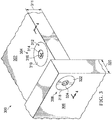
- Panel system 300 is a physical implementation of panel system 204 of Figure 2 .
- Panel system 300 includes first composite sandwich panel 302, cam assembly 304, second composite sandwich panel 306, and stud receiving assembly 308.
- First composite sandwich panel 302 has first hole 310 extending through thickness 311 of first composite sandwich panel 302.
- Cam assembly 304 is positioned within first hole 310.
- Cam assembly 304 comprises housing 312 and cam connector 314 rotatable within housing 312.
- Cam connector 314 is configured to engage a head of a stud.
- Cam connector 314 has cam drive 316.
- Cam connector 314 is rotated within housing 312 by using a driver that engages cam drive 316.
- Cam drive 316 can be a drive for a Phillips head screwdriver. However, cam drive 316 may take the form of any desirable drive.
- Second composite sandwich panel 306 has second hole 318 extending through thickness 320 of second composite sandwich panel 306.
- Stud receiving assembly 308 is positioned within second hole 318.
- Stud receiving assembly 308 comprises inner stud case 322.
- Inner stud case 322 has case drive 324.
- a thickness of stud receiving assembly 308 is changed using case drive 324.
- Case drive 324 may be used to change the thickness of stud receiving assembly 308 to accommodate the tolerance of thickness 320 of second composite sandwich panel 306.
- case drive 324 is a hex socket drive.
- case drive 324 may take the form of any desirable type of drive.
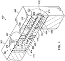
- View 400 is an isometric cross-sectional view of panel system 300 of Figure 3 from direction 4-4.
- stud receiving assembly 308 in Figure 3 comprises outer stud case 402 and inner stud case 322. Internal threads 404 of outer stud case 402 engage external threads 406 of inner stud case 322. By rotating inner stud case 322 using case drive 324, thickness 408 of stud receiving assembly 308 is changed. By rotating inner stud case 322 using case drive 324, external threads 406 move relative to internal threads 404.
- Stud receiving assembly 308 has internal retaining channels 410 configured to secure first end 412 of stud 414.
- Stud 414 comprises plurality of retaining fins 416 configured to engage internal retaining channels 410 of stud receiving assembly 308.
- Housing 312 has opening 418 configured to receive head 420 of stud 414.
- Housing 312 comprises inner cam case 422 and outer cam case 424.
- First hole 426 in inner cam case 422 and second hole 428 in outer cam case 424 form opening 418.
- inner cam case 422 and outer cam case 424 have a friction fit. The friction fit retains inner cam case 422 within outer cam case 424.
- first composite sandwich panel 302 and second composite sandwich panel 306 appear to be solid, this is for simplicity of illustration only. In practice, first composite sandwich panel 302 and second composite sandwich panel 306 would each have a core layer of material that is sandwiched between a first layer of material and a second layer of material. Further, instead of first composite sandwich panel 302 and second composite sandwich panel 306, the panels to be joined may be solid panels. Although described as first composite sandwich panel 302 and second composite sandwich panel 306, the panels to be joined may be formed of any desirable material.
- View 500 is a side cross-sectional view of panel system 300 of Figure 3 .
- Panel system 300 forms joint 502.
- joint 502 is a butt joint between first composite sandwich panel 302 and second composite sandwich panel 306.
- Panel system 300 may be formed in at least two separate steps. For example, cam assembly 304 and stud receiving assembly 308 may be inserted into first composite sandwich panel 302 and second composite sandwich panel 306, respectively, during a separate step other than a joining step.
- first composite sandwich panel 302 and second composite sandwich panel 306 may be placed into first composite sandwich panel 302 and second composite sandwich panel 306 during an insertion step. Potting material is applied between these inserts and the respective panel of first composite sandwich panel 302 or second composite sandwich panel 306.
- Cam assembly 304 and stud receiving assembly 308 may be inserted into first composite sandwich panel 302 and second composite sandwich panel 306 during this pre-existing insertion step.
- cam assembly 304 and stud receiving assembly 308 By inserting cam assembly 304 and stud receiving assembly 308 during a pre-existing insertion step for other inserts, potting material 503 within first hole 310 contacting cam assembly 304 and first composite sandwich panel 302 and potting material 504 within second hole 318 of Figure 3 , contacting stud receiving assembly 308 and second composite sandwich panel 306 is applied and cured when other inserts are also receiving potting material.
- a pre-existing potting material application step at least one of manufacturing time, manufacturing cost, or waste may be reduced.
- At least one of first composite sandwich panel 302 or second composite sandwich panel 306 may receive additional manufacturing processes prior to joining. First composite sandwich panel 302 and second composite sandwich panel 306 are then joined in a separate joining step from the insertion and potting step.
- first composite sandwich panel 302 and second composite sandwich panel 306 may be joined using only one tool and no potting material.
- first end 412 of stud 414 is inserted into stud receiving assembly 308.
- Head 420 of stud 414 is then inserted into opening 418 of housing 312.
- cam connector 314 is rotated using cam drive 316. Rotating cam connector 314 relative to head 420 of stud 414 secures head 420 within housing 312. As depicted, rotating cam connector 314 a quarter turn secures head 420 of stud 414.
- View 600 is an exploded view of panel system 300 of Figure 3 .
- Cam assembly 700 is a physical implementation of cam assembly 212 of Figure 2 .
- Cam assembly 700 may be the same as cam assembly 304 of Figure 3 .
- Cam assembly 700 includes outer cam case 702, inner cam case 704, and cam connector 706. As depicted, cam connector 706 may be rotated relative to housing 708 and formed by outer cam case 702 and inner cam case 704, by engaging cam drive 710.
- Potting material may be applied between cam assembly 700 and a composite sandwich panel such as composite sandwich panel 209 of Figure 2 or first composite sandwich panel 302 of Figure 3 . Potting material may be applied between cam assembly 700 and a composite sandwich panel by injection. More specifically, number of notches 712 in inner cam case 704 may receive a nozzle for injection of potting material between cam assembly 700 and a composite sandwich panel. Number of notches 712 includes notch 714 and notch 716. Number of notches 712 is a physical implementation of number of notches 270 of Figure 2 .
- Lip 718 is present on outer cam case 702 to discourage potting material from entering opening 720 of housing 708. Lip 718 may contact the composite sandwich panel to provide a barrier to the potting material.
- View 800 is a cross-sectional view of cam assembly 700 of Figure 7 .
- gap 802 and gap 804 are present between outer cam case 702 and inner cam case 704. Gap 802 and gap 804 will change if thickness 806 of cam assembly 700 is changed to accommodate tolerances of a composite sandwich panel.
- View 900 is a view of outer cam case 702 removed from cam assembly 700 of Figure 7 .
- outer cam case 702 has opening 902.
- Diameter 904 is configured to receive a portion of inner cam case 704. More specifically, diameter 904 of outer cam case 702 is configured to have a resistance fit with a portion of inner cam case 704.
- FIG. 10 an illustration of an isometric view of an inner cam case is depicted in accordance with the present invention.
- View 1000 is a view of inner cam case 704 removed from cam assembly 700.
- inner cam case 704 has hole 1002.
- a driver may be inserted into hole 1002 to engage cam drive 710 of Figure 7 .
- Body 1004 of inner cam case 704 has diameter 1006.
- Diameter 1006 is configured such that body 1004 can be inserted into opening 902 of outer cam case 702 of Figure 9 . Further, diameter 1006 is configured to have a resistance fit with diameter 904 of outer cam case 702 in Figure 9 .
- View 1100 is a view of cam connector 706 removed from cam assembly 700.
- cam connector 706 has locking mechanism 1102.
- locking mechanism 1102 contacts a head of a stud.
- Locking mechanism 1102 retains the head of the stud within cam assembly 700.
- Locking mechanism 1102 contacts the head of the stud and provides friction to discourage rotation of cam connector 706 relative to the stud. The friction discourages removal of the stud from cam assembly 700 due to the movement of the composite sandwich panels or other inadvertent removal of the stud.
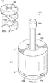
- Stud receiving assembly 1200 is a physical implementation of stud receiving assembly 214 of Figure 2 .
- Stud receiving assembly 1200 may be the same as stud receiving assembly 308 of Figure 3 .
- Stud 1202 is a physical implementation of stud 221 of Figure 2 .
- Stud 1202 may be the same as stud 414 of Figure 4 .
- stud receiving assembly 1200 includes outer stud case 1204 and inner stud case 1206.
- Case drive 1208 may be used to change thickness 1210 of stud receiving assembly 1200. When thickness 1210 is changed, channel 1212 between outer stud case 1204 and inner stud case 1206 increases or decreases in size.
- case drive 1208 takes the form of a hex socket. To provide torque, a case drive may also be present in inner stud case 1206.
- a first end of stud 1202 extends through case drive 1208 into stud receiving assembly 1200.
- Head 1214 remains outside of stud receiving assembly 1200.
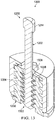
- View 1300 is an isometric cross-sectional view of stud receiving assembly 1200 of Figure 12 .
- first end 1302 of stud 1202 has plurality of external retaining fins 1304.
- the plurality of external retaining fins 1304 may be referred to as simply retaining fins, plurality of retaining fins, or external retaining fins.
- Plurality of external retaining fins 1304 are configured to be inserted into hole 1306 of inner stud case 1206 and be retained by internal retaining channels 1308 of inner stud case 1206.
- Material for stud 1202 is selected to provide a desirable elastic property for insertion without permanent deformation. Further, material for stud 1202 is selected to provide desirable strength to prevent inadvertent removal of stud 1202.
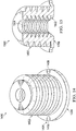
- View 1400 is a view of inner stud case 1206 removed from stud receiving assembly 1200 of Figure 12 .
- Inner stud case 1206 has external threads 1402 configured to engage internal threads of outer stud case 1204.
- Inner stud case 1206 has number of notches 1404. Potting material (not depicted) may be applied between stud receiving assembly 1200 and a composite sandwich panel such as composite sandwich panel 210 of Figure 2 or second composite sandwich panel 306 of Figure 3 .
- Potting material may be applied between stud receiving assembly 1200 and a composite sandwich panel by injection. More specifically, number of notches 1404 in inner stud case 1206 may receive a nozzle for injection of potting material between stud receiving assembly 1200 and a composite sandwich panel. Number of notches 1404 includes notch 1406 and notch 1408. Number of notches 1404 is a physical implementation of number of notches 280 of Figure 2 . The number of notches 1404 may have a substantially similar shape to number of notches 714 of cam assembly 700 of Figure 7 . By having substantially similar shapes, the same nozzle may be used to inject potting material into number of notches 1404 and number of notches 714.
- View 1500 is a cross-section view of inner stud case 1206 of Figure 12 .
- internal retaining channels 1308 of inner stud case 1206, which are configured to retain a first end of stud 1202, are visible.
- case drive 1502 is visible. As depicted, case drive 1502 is a hexagonal socket. The case drive 1502 may take the form of any desirable drive.
- View 1600 is an isometric view of stud 1202 prior to insertion into stud receiving assembly 1200 of Figure 12 .
- Stud 1202 may be referred to as a "Christmas tree stud.”
- Stud 1202 has plurality of external retaining fins 1304, configured to be inserted into hole 1306 of inner stud case 1206 and to be retained by internal retaining channels 1308 of inner stud case 1206.
- Stud 1202 has head 1214 configured to be retained by a cam connector, such as cam connector 706 of Figure 7 .
- Stud 1202 is inserted into stud receiving assembly 1200 without any tools. Stud 1202 is retained within stud receiving assembly 1200 by using a single tool to rotate cam connector 706. Thus, stud 1202, stud receiving assembly 1200, and cam connector 706 may form a joining assembly with a lower joining time than conventional joining systems.
- View 1700 is a view of outer stud case 1204 removed from stud receiving assembly 1200 of Figure 12 .
- outer stud case 1204 has internal threads 1702. Internal threads 1702 engage with external threads 1402 of inner stud case 1206 of Figure 12 .
- Method 1800 may be used to join composite sandwich panel 209 and composite sandwich panel 210 of Figure 2 . Further, method 1800 may be used to form panel system 300 of Figures 3-5 . Method 1800 inserts a cam assembly into a first hole extending through a thickness of a first composite panel, the cam assembly comprises a housing and a cam connector rotatable within the housing, and the cam connector is configured to engage a head of a stud (operation 1802 ). The cam assembly can be inserted into the first composite panel when other inserts are inserted into the first composite panel.
- Method 1800 inserts a stud receiving assembly within a second hole extending through a thickness of a second composite panel, the stud receiving assembly having retaining channels configured to secure a first end of the stud within the stud receiving assembly (operation 1804 ). Afterwards the process terminates.
- the stud receiving assembly can be inserted into the second composite panel when other inserts are inserted into the second composite panel.
- each block in the flowcharts or block diagrams may represent a module, a segment, a function, and/or a portion of an operation or step.
- method 1800 may further comprise rotating an inner stud case of the stud receiving case relative to an outer stud case of the stud receiving case to adjust a length of the stud receiving case.
- method 1800 may further comprise injecting a potting material into the first hole between the cam assembly and the first composite panel; and injecting the potting material into the second hole between the stud receiving assembly and the second composite panel. Injecting the potting material into the first hole and the second hole is performed during a potting step for other inserts for at least one of the first composite panel or the second composite panel.
- Method 1800 further comprises inserting the first end of the stud into the stud receiving assembly, inserting the head of the stud into the housing of the cam assembly, and rotating the cam connector within the housing to engage the head of the stud and form a joint between the first composite sandwich panel and the second composite sandwich panel. Inserting the first end of the stud into the stud receiving assembly can be performed during an assembly step following the potting step.
- the joint may be a butt joint.
- the first composite sandwich panel and the second composite sandwich panel may comprise a plurality of composite skins, and method 1800 may further comprise applying loads to the joint and transferring applied shear loads to the plurality of composite skins by the stud.
- aircraft manufacturing and service method 1900 may be described in the context of aircraft manufacturing and service method 1900 as shown in Figure 19 and aircraft 2000 as shown in Figure 20 .
- Figure 19 an illustration of an aircraft manufacturing and service method is depicted in accordance with the present invention.
- aircraft manufacturing and service method 1900 may include specification and design 1902 of aircraft 2000 in Figure 20 and material procurement 1904.
- aircraft 2000 During production, component and subassembly manufacturing 1906 and system integration 1908 of aircraft 2000 takes place. Thereafter, aircraft 2000 may go through certification and delivery 1910 in order to be placed in service 1912. While in service 1912 by a customer, aircraft 2000 is scheduled for routine maintenance and service 1914, which may include modification, reconfiguration, refurbishment, and other maintenance or service.
- Each of the processes of aircraft manufacturing and service method 1900 may be performed or carried out by a system integrator, a third party, and/or an operator.
- the operator may be a customer.
- a system integrator may include, without limitation, any number of aircraft manufacturers or major-system subcontractors
- a third party may include, without limitation, any number of vendors, subcontractors, or suppliers
- an operator may be an airline, a leasing company, a military entity, a service organization, and so on.
- aircraft 2000 is produced by aircraft manufacturing and service method 1900 in Figure 19 and may include airframe 2002 with a plurality of systems 2004 and interior 2006.
- systems 2004 include one or more of propulsion system 2008, electrical system 2010, hydraulic system 2012, and environmental system 2014. Any number of other systems may be included.
- an aerospace example is shown, the present invention may be applied to other industries, such as the automotive industry.
- Apparatuses and methods embodied herein may be employed during at least one of the stages of aircraft manufacturing and service method 1900.
- One or more illustrative examples may be used during component and subassembly manufacturing 1906 of Figure 19 .
- fastening system 206 of Figure 2 may be used to join composite sandwich panels during component and subassembly manufacturing 1906.
- fastening system 206 of Figure 2 may be used to join composite sandwich panels for replacement parts during maintenance and service 1914 of Figure 19 .
- the illustrative examples provide a panel fastening system including a pair of inserts, a cam assembly and a stud receiving assembly.
- the panel fastening system also includes a stud where one of the inserts uses cam action to compression lock on to the stud to couple the panels together. This allows for a potter to position all of the inserts, and then using an assembler only to screw one end of the stud to one insert then compression lock the other end of the stud to the other insert to couple the panels together.
- the assembler may only take a few seconds to couple the stud to the inserts. This can save time and costs associated with forming monuments from cored composite panels by moving the labor upstream in the manufacturing process. Specifically, by using a pre-existing potting step, additional potting dry time specifically for the panel fastening system may not be added to the monument. The potting material of the panel fastening system may dry while potting material for other inserts dries. Additionally, by using a pre-existing potting step, additional waste may not be created for the panel fastening system specifically. The waste for potting the panel fastening system is shared with the other inserts of the pre-existing potting step.
- this fastening system can have up to 30 thousandths per hole of tolerance, so the accuracy of the machining may be reduced to save time and costs.
- the fastening system may be designed to be slightly stronger (tensile, in-plane shear, and out-plane shear) than the composite sandwich panels so the insert and stud do not break in the panel. Repairs and/or replacements may be easier than if the fastener broke in the panel.
Landscapes
- Engineering & Computer Science (AREA)
- General Engineering & Computer Science (AREA)
- Mechanical Engineering (AREA)
- Architecture (AREA)
- Aviation & Aerospace Engineering (AREA)
- Civil Engineering (AREA)
- Structural Engineering (AREA)
- Connection Of Plates (AREA)
- Snaps, Bayonet Connections, Set Pins, And Snap Rings (AREA)
- Mutual Connection Of Rods And Tubes (AREA)
Abstract
Description
- The present disclosure relates generally to joining panels, and more specifically, to joining composite sandwich panels. Yet more specifically, the present disclosure includes a fastening system for joining a first composite sandwich panel and a second composite sandwich panel.
- A composite panel may be considered a composite sandwich panel when the composite panel is comprised of a core layer of material that is sandwiched between a first layer of material and a second layer of material. The core layer of material may have a greater thickness than the first and second layers of material. In some cases, the core layer of material may be comprised of a honeycomb material, a foam material, or some other structure. A honeycomb material may be a material that has a honeycomb-like structure.
- Methods for joining composite sandwich panels are currently undesirably time consuming. Further, joining methods for joining composite sandwich panels generate an undesirable amount of waste. For example, applying potting material to conventional joining hardware produces material, protective gear, and application tool waste. Therefore, it would be desirable to have a method and apparatus that takes into account at least some of the issues discussed above, as well as other possible issues. For example, it would be desirable to have a method and apparatus that reduces the time for joining composite sandwich panels.
- The present invention provides a fastening system for joining a first composite sandwich panel and a second composite sandwich panel. The fastening system comprises a cam assembly and a stud receiving assembly. The cam assembly is configured to be positioned within a first hole extending through a thickness of a first composite sandwich panel. The cam assembly comprises a housing and a cam connector rotatable within the housing. The cam connector is configured to engage a head of a stud. The stud receiving assembly is configured to be positioned within a second hole extending through a thickness of a second composite sandwich panel. The stud receiving assembly has internal retaining channels configured to secure a first end of the stud of the stud within the receiving assembly.
- The present invention also provides a panel system for forming a monument. The panel system comprises a first composite sandwich panel, a cam assembly, a second composite sandwich panel, and a stud receiving assembly. The first composite sandwich panel has a first hole extending through a thickness of the first composite sandwich panel. The cam assembly is positioned within the first hole. The cam assembly comprises a housing and a cam connector rotatable within the housing. The cam connector is configured to engage a head of a stud. The second composite sandwich panel has a second hole extending through a thickness of the second composite sandwich panel. The stud receiving assembly is positioned within the second hole. The stud receiving assembly has internal retaining channels configured to secure a first end of the stud within the stud receiving assembly.
- The present invention also provides a method. A cam assembly is inserted into a first hole extending through a thickness of a first composite panel, the cam assembly comprising a housing and a cam connector rotatable within the housing, wherein the cam connector is configured to engage a head of a stud. A stud receiving assembly is inserted within a second hole extending through a thickness of a second composite panel, the stud receiving assembly, having internal retaining channels, is configured to secure a first end of the stud within the stud receiving assembly.
- The present invention will now be detailed with reference to the following figures:
-
Figure 1 is an illustration of an aircraft in which the present invention may be implemented; -
Figure 2 is an illustration of a block diagram of a manufacturing environment in accordance with the present invention; -
Figure 3 is an illustration of an isometric view of a panel system in accordance with the present invention; -
Figure 4 is an illustration of an isometric cross-sectional view of a panel system in accordance with the present invention -
Figure 5 is an illustration of a side cross-sectional view of a panel system in accordance with the present invention; -
Figure 6 is an illustration of an exploded isometric view of a panel system in accordance with the present invention; -
Figure 7 is an illustration of an isometric view of a cam assembly in accordance with the present invention; -
Figure 8 is an illustration of an isometric cross-sectional view of a cam assembly in accordance with the present invention; -
Figure 9 is an illustration of an isometric view of an outer cam case in accordance with the present invention; -
Figure 10 is an illustration of an isometric view of an inner cam case in accordance with the present invention; -
Figure 11 is an illustration of an isometric view of a cam connector in accordance with the present invention; -
Figure 12 is an illustration of an isometric view of a stud receiving assembly and a stud in accordance with the present invention; -
Figure 13 is an illustration of an isometric cross-sectional view of a stud receiving assembly and a stud in accordance with the present invention; -
Figure 14 is an illustration of an isometric view of an inner stud case in accordance with the present invention; -
Figure 15 is an illustration of an isometric cross-sectional view of an inner stud case in accordance with the present invention; -
Figure 16 is an illustration of an isometric view of a stud in accordance with the present invention; -
Figure 17 is an illustration of a side cross-sectional view of an outer stud case in accordance with the present invention; -
Figure 18 is an illustration of a flowchart of a method of joining two composite sandwich panels in accordance with the present invention; -
Figure 19 is an illustration of an aircraft manufacturing and service method in the form of a block diagram in accordance with the present invention; and -
Figure 20 is an illustration of an aircraft in the form of a block diagram in which an the present invention may be implemented. - The present invention recognizes and takes into account one or more different considerations. For example, the present invention recognizes and takes into account that some known monuments for use in vehicles may be formed from lightweight composite panels having a core. The present invention recognizes and takes into account that the core is not configured to bear in-plane shear loads. Rather, the skins of the composite panels bear shear loading on the panel.
- The present invention further recognizes and takes into account that current systems to join composite panels may utilize fastener and bracket designs. In these designs, turning of physical fasteners joins two panels. However, fastener and bracket designs may be heavier than desired and use a larger amount of labor than desired.
- The present invention further recognizes and takes into account that fastener and bracket designs use a large number of fasteners, heavy metal brackets, and potted inserts to achieve the loading specifications for aircraft parts. The i present invention also recognizes and takes into account that some fasteners may be installed into the incorrect holes. Further, the present invention recognizes and takes into account installing the correct fasteners in the correct holes may be more time-consuming than desired.
- The present invention recognizes and takes into account that some fastener-less assembling methods may be used. However, the present invention recognizes and takes into account that these methods may require precision machining and fitting of the panels.
- Further, the present invention recognizes and takes into account that these fastener-less assembly methods use a potting material that may add an additional undesirable wait time and produce an undesirable amount of waste. For example, the present invention recognize and takes into account that applying a potting compound which uses a large amount of support materials for installing the potting, cleaning the potting compound, moving the compound and personnel protection.
- The present invention recognizes and takes into account that conventional knock-down fasteners may provide a means of quickly joining two components. The present invention recognizes and takes into account that knock-down fasteners may join two components with little to no waste. However, the present invention recognizes and takes into account that conventional knock-down fasteners cannot be used with composite panels having cores because the core cannot bear the shear load exerted by these conventional fasteners.
- Referring now to the figures and, in particular, with reference to
Figure 1 , an illustration of an aircraft is depicted in which the present invention may be implemented. In this illustrative example,aircraft 100 haswing 102 andwing 104 attached tobody 106.Aircraft 100 includesengine 108 attached towing 102 andengine 110 attached towing 104. -
Body 106 hastail section 112.Horizontal stabilizer 114,horizontal stabilizer 116, andvertical stabilizer 118 are attached totail section 112 ofbody 106. -
Aircraft 100 is an example of an aircraft having a panel fastening system. For example,aircraft 100 is an example of an aircraft having a panel fastening system joining composite sandwich panels as described in at least one ofwing 102,wing 104, orbody 106. - As used herein, the phrase "at least one of," when used with a list of items, means different combinations of one or more of the listed items may be used, and only one of each item in the list may be needed. In other words, "at least one of" means any combination of items or number of items may be used from the list, but not all of the items in the list are required. The item may be a particular object, a thing, or a category.
- For example, "at least one of item A, item B, or item C" may include, without limitation, item A, item A and item B, or item B. This example also may include item A, item B, and item C or item B and item C. Of course, any combination of these items may be present. In other examples, "at least one of" may be, for example, without limitation, two of item A, one of item B, and ten of item C; four of item B and seven of item C; or other suitable combinations.
- Although the illustrative examples are described with respect to an aircraft, the present invention may be applied to other types of monuments. The monument may be, for example, a mobile structure, a stationary structure, a land-based structure, an aquatic-based structure, or a space-based structure. More specifically, the monument may be a surface ship, a tank, a personnel carrier, a train, a spacecraft, a space station, a satellite, a submarine, a manufacturing facility, a building, or other suitable structures. Further the monument may be a portion of any desirable structure.
- Turning now to
Figure 2 , an illustration of a block diagram of a manufacturing environment is depicted in accordance with the present invention.. Portions ofaircraft 100 may be manufactured inmanufacturing environment 200. For example,monument 202 ofmanufacturing environment 200 may be a component of one ofwing 102,wing 104, orbody 106 ofaircraft 100. -
Panel system 204 is used to formmonument 202.Panel system 204 includesfastening system 206 for joiningcomposite panel 207 andcomposite panel 208.Composite panel 207 may take the form ofcomposite sandwich panel 209.Composite panel 208 may take the form ofcomposite sandwich panel 210. - The
fastening system 206 may joincomposite sandwich panel 209 andcomposite sandwich panel 210.Fastening system 206 comprisescam assembly 212 andstud receiving assembly 214.Cam assembly 212 is configured to be positioned withinfirst hole 216 extending throughthickness 217 ofcomposite sandwich panel 209. In some illustrative examples,composite sandwich panel 209 may be referred to as a first composite sandwich panel. -
Cam assembly 212 comprises housing 218 andcam connector 219 which is rotatable within housing 218.Cam connector 219 is configured to engage head 220 ofstud 221. -
Stud receiving assembly 214 is configured to be positioned withinsecond hole 222 extending throughthickness 224 ofcomposite sandwich panel 210.Composite sandwich panel 210 may be referred to as a second composite sandwich panel.Stud receiving assembly 214 hasinternal retaining channels 226 configured to securefirst end 228 ofstud 221 withinstud receiving assembly 214. -
Stud receiving assembly 214 includesinner stud case 230 andouter stud case 232.External threads 234 ofinner stud case 230 engageinternal threads 236 ofouter stud case 232.Thickness 238 ofstud receiving assembly 214 is adjusted by moving at least one ofexternal threads 234 orinternal threads 236 relative to each other.Thickness 238 is adjusted such thatthickness 238 is substantially the same asthickness 224. Adjustingthickness 238 compensates for tolerances inthickness 224 ofcomposite sandwich panel 210. -
Thickness 238 ofstud receiving assembly 214 is adjusted by applying torque to at least one of case drive 240 ofouter stud case 232 or case drive 242 ofinner stud case 230.Case drive 240 and case drive 242 may be any desirable type of drive.Case drive 240 and case drive 242 may be the same type of drive. For example, case drive 240 and case drive 242 may both be hexagonal sockets.Case drive 240 and case drive 242 may be different types of drives. For example, case drive 240 may be a drive for a flathead screwdriver while case drive 242 is a socket. -
First end 228 ofstud 221 is inserted into case drive 242 to securefirst end 228 ofstud 221 withinstud receiving assembly 214.Stud 221 comprises plurality of retaining fins 244 configured to engageinternal retaining channels 226 ofstud receiving assembly 214. - When
first end 228 ofstud 221 is inserted intostud receiving assembly 214, plurality of retaining fins 244 elastically bend to enterinternal retaining channels 226. Afterwards, the strength of plurality of retaining fins 244 retainsfirst end 228 withininner stud case 230. -
Stud 221 may be referred to as a Christmas tree stud. The design and material ofstud 221 are selected to yield to be inserted intostud receiving assembly 214. The design and material ofstud 221 are selected to carry tension load into shear load. - The material for
stud 221 is formed of a material configured to provide one-way plastic deformation.Stud 221 may be formed from a super engineering grade plastic with high yield moduluses and a high deflection temperature. A material forstud 221 desirably deforms but maintains tension. In some illustrative examples, housing 218 andstud receiving assembly 214 are formed of the same material asstud 221. Housing 218 andstud receiving assembly 214 may be formed of materials different fromstud 221. For example, at least one ofstud receiving assembly 214 or housing 218 may be formed of aluminum or another relatively low weight metal, whilestud 221 is formed of a high performing thermoplastic such as PEEK. - Housing 218 of
cam assembly 212 comprises opening 246 configured to receive head 220 ofstud 221.First hole 247 ininner cam case 248 andsecond hole 249 inouter cam case 250 form opening 246 of housing 218. - Housing 218 comprises
inner cam case 248 andouter cam case 250.Inner cam case 248 andouter cam case 250 have a friction fit. - After head 220 on
second end 252 ofstud 221 is inserted intoopening 246,cam connector 219 is rotated usingcam drive 254. Cam drive 254 may take the form of any desirable drive. For example, cam drive 254 may be a female or a male drive. As another example, cam drive 254 may be a drive for a screwdriver or asocketCam drive 254 can be a drive for a Phillips head screwdriver. Cam drive 254 may be selected based on availability of the drive tool. For example, acam drive 254 with a common associated drive tool may allow for multiple drive tools to be available. Further, if the drive tool is common, the drive tool may be less expensive than specialty drive tools. -
Cam connector 219 may be rotated any desirable amount.Cam connector 219 can be rotated a quarter turn usingcam drive 254. Rotatingcam connector 219 retains head 220 ofstud 221 withincam assembly 212. More specifically, rotatingcam connector 219places locking mechanism 256 ofcam connector 219 in contact with head 220 ofstud 221.Locking mechanism 256 discourages rotation ofcam connector 219 due to friction with head 220. Further,locking mechanism 256 prevents head 220 from exitingopening 246 of housing 218. Rotatingcam connector 219 usingcam drive 254 compression locks onto head 220 ofstud 221 to couplecomposite panel 207 andcomposite panel 208 together. - By rotating
cam connector 219,composite sandwich panel 209 andcomposite sandwich panel 210 are connected to form joint 258. Joint 258 can take the form of a butt joint. ,Stud 221 may extend out ofcomposite sandwich panel 210 perpendicular tofirst hole 216 ofcomposite panel 207.Stud 221 may extend throughthird hole 260 ofcomposite panel 207.Third hole 260 is perpendicular tofirst hole 216. Whenfirst hole 216 is positioned at an edge ofcomposite panel 207,third hole 260 is not present. - When
composite panel 207 takes the form ofcomposite sandwich panel 209,composite sandwich panel 209 comprisescore 262 betweenskin 264 andskin 266.Core 262 may behoneycomb core 268. Whencomposite panel 207 includeshoneycomb core 268,first hole 216 may open into air pockets withinhoneycomb core 268. An adhesive material, such as a potting material, may be injected into these air pockets. Adhesive material may be injected into the air pockets through number ofnotches 270 ofinner cam case 248. - When
composite panel 208 takes the form ofcomposite sandwich panel 210,composite sandwich panel 210 comprisescore 272 betweenskin 274 andskin 276.Core 272 may behoneycomb core 278. Whencomposite panel 210 includeshoneycomb core 278,second hole 222 may open into air pockets withinhoneycomb core 278. An adhesive material, such as a potting material, may be injected into these air pockets. Adhesive material may be injected into the air pockets through number ofnotches 280 ofinner stud case 230. - When loads are applied to joint 258, applied shear loads will be transferred to
skin 264,skin 266,skin 274, andskin 276 bystud 221. More specifically, when loads are applied to joint 258,skin 264,skin 266,skin 274, andskin 276 carry the majority of the load.Core 262 andcore 272 carry little to no load. Any shear or bending loads oncomposite panel 207 orcomposite panel 208 will transfer throughfastening system 206 to the skins of the other ofcomposite panel 207 orcomposite panel 208 as shear or bending loads. - The illustrations of
manufacturing environment 200 inFigure 2 are not meant to imply physical or architectural limitations to the manner in which the present invention may be implemented. Other components in addition to or in place of the ones illustrated may be used. Some components may be unnecessary. Also, the blocks are presented to illustrate some functional components. One or more of these blocks may be combined, divided, or combined and divided into different blocks when implemented in an illustrative embodiment. - For example, although
stud 221 is discussed as being formed of a polymeric material, in someillustrative examples stud 221 may be formed of aluminum or another light weight metal. In these illustrative examples, instead ofstud 221 having plurality of retaining fins 244,stud 221 may haveinternal retaining channels 226, whileinner stud case 230 has plurality of retaining fins 244 formed of a thermoplastic material. - As another example, although
panel system 204 is described as havingcomposite panel 207 andcomposite panel 208,panel system 204 may have panels of any desirable material. For example,panel system 204 may include panels of metallic materials, polymeric materials, ceramics, or any combination thereof.Fastening system 206 andstud 221 may be used to join panels of any desirable material. - Further, although
monument 202 can be a component ofaircraft 100,monument 202 could be anydesirable monument 202.Monument 202 may be in an area other than aerospace applications. - Yet further, portions of
fastening system 206 may be formed of any desirable material. Components offastening system 206 may be formed of the same material or different materials. Components offastening system 206 may be formed of at least one of a composite, a metal, a ceramic, a polymer, or any other desirable material. - Turning now to
Figure 3 , an illustration of an isometric view of a panel system is depicted in accordance with the present invention.Panel system 300 is a physical implementation ofpanel system 204 ofFigure 2 . -
Panel system 300 includes firstcomposite sandwich panel 302,cam assembly 304, secondcomposite sandwich panel 306, andstud receiving assembly 308. Firstcomposite sandwich panel 302 hasfirst hole 310 extending throughthickness 311 of firstcomposite sandwich panel 302. -
Cam assembly 304 is positioned withinfirst hole 310.Cam assembly 304 compriseshousing 312 andcam connector 314 rotatable withinhousing 312.Cam connector 314 is configured to engage a head of a stud. -
Cam connector 314 hascam drive 316.Cam connector 314 is rotated withinhousing 312 by using a driver that engagescam drive 316. Cam drive 316 can be a drive for a Phillips head screwdriver. However, cam drive 316 may take the form of any desirable drive. - Second
composite sandwich panel 306 hassecond hole 318 extending throughthickness 320 of secondcomposite sandwich panel 306.Stud receiving assembly 308 is positioned withinsecond hole 318.Stud receiving assembly 308 comprisesinner stud case 322.Inner stud case 322 hascase drive 324. A thickness ofstud receiving assembly 308 is changed using case drive 324.Case drive 324 may be used to change the thickness ofstud receiving assembly 308 to accommodate the tolerance ofthickness 320 of secondcomposite sandwich panel 306. As illustrated, case drive 324 is a hex socket drive. However, case drive 324 may take the form of any desirable type of drive. - Turning now to
Figure 4 , an illustration of an isometric cross-sectional view of a panel system is depicted in accordance with the present invention.. View 400 is an isometric cross-sectional view ofpanel system 300 ofFigure 3 from direction 4-4. - As can be seen in
view 400,stud receiving assembly 308 inFigure 3 comprisesouter stud case 402 andinner stud case 322.Internal threads 404 ofouter stud case 402 engageexternal threads 406 ofinner stud case 322. By rotatinginner stud case 322 using case drive 324,thickness 408 ofstud receiving assembly 308 is changed. By rotatinginner stud case 322 using case drive 324,external threads 406 move relative tointernal threads 404. -
Stud receiving assembly 308 hasinternal retaining channels 410 configured to securefirst end 412 ofstud 414.Stud 414 comprises plurality of retainingfins 416 configured to engageinternal retaining channels 410 ofstud receiving assembly 308. -
Housing 312 has opening 418 configured to receivehead 420 ofstud 414.Housing 312 comprisesinner cam case 422 andouter cam case 424.First hole 426 ininner cam case 422 andsecond hole 428 inouter cam case 424form opening 418. As depicted,inner cam case 422 andouter cam case 424 have a friction fit. The friction fit retainsinner cam case 422 withinouter cam case 424. - Although, as depicted in
Figure 4 , firstcomposite sandwich panel 302 and secondcomposite sandwich panel 306 appear to be solid, this is for simplicity of illustration only. In practice, firstcomposite sandwich panel 302 and secondcomposite sandwich panel 306 would each have a core layer of material that is sandwiched between a first layer of material and a second layer of material. Further, instead of firstcomposite sandwich panel 302 and secondcomposite sandwich panel 306, the panels to be joined may be solid panels. Although described as firstcomposite sandwich panel 302 and secondcomposite sandwich panel 306, the panels to be joined may be formed of any desirable material. - Turning now to
Figure 5 , an illustration of a side cross-sectional view of a panel system is depicted in accordance with the present invention.. View 500 is a side cross-sectional view ofpanel system 300 ofFigure 3 .Panel system 300 forms joint 502. As depicted, joint 502 is a butt joint between firstcomposite sandwich panel 302 and secondcomposite sandwich panel 306. -
Panel system 300 may be formed in at least two separate steps. For example,cam assembly 304 andstud receiving assembly 308 may be inserted into firstcomposite sandwich panel 302 and secondcomposite sandwich panel 306, respectively, during a separate step other than a joining step. - For example, other inserts (not depicted) may be placed into first
composite sandwich panel 302 and secondcomposite sandwich panel 306 during an insertion step. Potting material is applied between these inserts and the respective panel of firstcomposite sandwich panel 302 or secondcomposite sandwich panel 306. -
Cam assembly 304 andstud receiving assembly 308 may be inserted into firstcomposite sandwich panel 302 and secondcomposite sandwich panel 306 during this pre-existing insertion step. By insertingcam assembly 304 andstud receiving assembly 308 during a pre-existing insertion step for other inserts, pottingmaterial 503 withinfirst hole 310 contactingcam assembly 304 and firstcomposite sandwich panel 302 andpotting material 504 withinsecond hole 318 ofFigure 3 , contactingstud receiving assembly 308 and secondcomposite sandwich panel 306 is applied and cured when other inserts are also receiving potting material. By using a pre-existing potting material application step, at least one of manufacturing time, manufacturing cost, or waste may be reduced. - At least one of first
composite sandwich panel 302 or secondcomposite sandwich panel 306 may receive additional manufacturing processes prior to joining. Firstcomposite sandwich panel 302 and secondcomposite sandwich panel 306 are then joined in a separate joining step from the insertion and potting step. - In the joining step, first
composite sandwich panel 302 and secondcomposite sandwich panel 306 may be joined using only one tool and no potting material. In the joining step,first end 412 ofstud 414 is inserted intostud receiving assembly 308.Head 420 ofstud 414 is then inserted into opening 418 ofhousing 312. Whenhead 420 ofstud 414 is withinhousing 312,cam connector 314 is rotated usingcam drive 316. Rotatingcam connector 314 relative to head 420 ofstud 414 secureshead 420 withinhousing 312. As depicted, rotating cam connector 314 a quarter turn secureshead 420 ofstud 414. - Turning now to
Figure 6 , an illustration of an exploded isometric view of a panel system is depicted in accordance with the present invention.. View 600 is an exploded view ofpanel system 300 ofFigure 3 . - Turning now to
Figure 7 , an illustration of an isometric view of a cam assembly is depicted in accordance with the present invention .Cam assembly 700 is a physical implementation ofcam assembly 212 ofFigure 2 .Cam assembly 700 may be the same ascam assembly 304 ofFigure 3 . -
Cam assembly 700 includesouter cam case 702,inner cam case 704, andcam connector 706. As depicted,cam connector 706 may be rotated relative tohousing 708 and formed byouter cam case 702 andinner cam case 704, by engagingcam drive 710. - Potting material (not depicted) may be applied between
cam assembly 700 and a composite sandwich panel such ascomposite sandwich panel 209 ofFigure 2 or firstcomposite sandwich panel 302 ofFigure 3 . Potting material may be applied betweencam assembly 700 and a composite sandwich panel by injection. More specifically, number ofnotches 712 ininner cam case 704 may receive a nozzle for injection of potting material betweencam assembly 700 and a composite sandwich panel. Number ofnotches 712 includesnotch 714 and notch 716. Number ofnotches 712 is a physical implementation of number ofnotches 270 ofFigure 2 . -
Lip 718 is present onouter cam case 702 to discourage potting material from enteringopening 720 ofhousing 708.Lip 718 may contact the composite sandwich panel to provide a barrier to the potting material. - Turning now to
Figure 8 , an illustration of an isometric cross-sectional view of a cam assembly is depicted in accordance with the present invention. View 800 is a cross-sectional view ofcam assembly 700 ofFigure 7 . - As depicted,
gap 802 andgap 804 are present betweenouter cam case 702 andinner cam case 704.Gap 802 andgap 804 will change ifthickness 806 ofcam assembly 700 is changed to accommodate tolerances of a composite sandwich panel. - Turning now to
Figure 9 , an illustration of an isometric view of an outer cam case is depicted in accordance with the present invention. View 900 is a view ofouter cam case 702 removed fromcam assembly 700 ofFigure 7 . As depicted,outer cam case 702 hasopening 902.Diameter 904 is configured to receive a portion ofinner cam case 704. More specifically,diameter 904 ofouter cam case 702 is configured to have a resistance fit with a portion ofinner cam case 704. - Turning now to
Figure 10 , an illustration of an isometric view of an inner cam case is depicted in accordance with the present invention.View 1000 is a view ofinner cam case 704 removed fromcam assembly 700. As depicted,inner cam case 704 hashole 1002. A driver may be inserted intohole 1002 to engage cam drive 710 ofFigure 7 .Body 1004 ofinner cam case 704 hasdiameter 1006.Diameter 1006 is configured such thatbody 1004 can be inserted into opening 902 ofouter cam case 702 ofFigure 9 . Further,diameter 1006 is configured to have a resistance fit withdiameter 904 ofouter cam case 702 inFigure 9 . - Turning now to
Figure 11 , an illustration of an isometric view of a cam connector is depicted in accordance with the present invention.View 1100 is a view ofcam connector 706 removed fromcam assembly 700. As depicted,cam connector 706 haslocking mechanism 1102. Whencam connector 706 is rotated withincam assembly 700,locking mechanism 1102 contacts a head of a stud.Locking mechanism 1102 retains the head of the stud withincam assembly 700.Locking mechanism 1102 contacts the head of the stud and provides friction to discourage rotation ofcam connector 706 relative to the stud. The friction discourages removal of the stud fromcam assembly 700 due to the movement of the composite sandwich panels or other inadvertent removal of the stud. - Turning now to
Figure 12 , an illustration of an isometric view of a stud receiving assembly and a stud is depicted in accordance with the present invention.Stud receiving assembly 1200 is a physical implementation ofstud receiving assembly 214 ofFigure 2 .Stud receiving assembly 1200 may be the same asstud receiving assembly 308 ofFigure 3 .Stud 1202 is a physical implementation ofstud 221 ofFigure 2 .Stud 1202 may be the same asstud 414 ofFigure 4 . - As depicted,
stud receiving assembly 1200 includesouter stud case 1204 andinner stud case 1206.Case drive 1208 may be used to changethickness 1210 ofstud receiving assembly 1200. Whenthickness 1210 is changed,channel 1212 betweenouter stud case 1204 andinner stud case 1206 increases or decreases in size. As depicted,case drive 1208 takes the form of a hex socket. To provide torque, a case drive may also be present ininner stud case 1206. - As depicted, a first end of
stud 1202 extends throughcase drive 1208 intostud receiving assembly 1200.Head 1214 remains outside ofstud receiving assembly 1200. - Turning now to
Figure 13 , an illustration of an isometric cross-sectional view of a stud receiving assembly and a stud is depicted in accordance with the present invention.View 1300 is an isometric cross-sectional view ofstud receiving assembly 1200 ofFigure 12 . - As depicted,
first end 1302 ofstud 1202 has plurality ofexternal retaining fins 1304. The plurality ofexternal retaining fins 1304 may be referred to as simply retaining fins, plurality of retaining fins, or external retaining fins. Plurality ofexternal retaining fins 1304 are configured to be inserted intohole 1306 ofinner stud case 1206 and be retained byinternal retaining channels 1308 ofinner stud case 1206. Material forstud 1202 is selected to provide a desirable elastic property for insertion without permanent deformation. Further, material forstud 1202 is selected to provide desirable strength to prevent inadvertent removal ofstud 1202. - Turning now to
Figure 14 , an illustration of an isometric view of an inner stud case is depicted in accordance with the present invention.View 1400 is a view ofinner stud case 1206 removed fromstud receiving assembly 1200 ofFigure 12 .Inner stud case 1206 hasexternal threads 1402 configured to engage internal threads ofouter stud case 1204. -
Inner stud case 1206 has number ofnotches 1404. Potting material (not depicted) may be applied betweenstud receiving assembly 1200 and a composite sandwich panel such ascomposite sandwich panel 210 ofFigure 2 or secondcomposite sandwich panel 306 ofFigure 3 . - Potting material may be applied between
stud receiving assembly 1200 and a composite sandwich panel by injection. More specifically, number ofnotches 1404 ininner stud case 1206 may receive a nozzle for injection of potting material betweenstud receiving assembly 1200 and a composite sandwich panel. Number ofnotches 1404 includesnotch 1406 andnotch 1408. Number ofnotches 1404 is a physical implementation of number ofnotches 280 ofFigure 2 . The number ofnotches 1404 may have a substantially similar shape to number ofnotches 714 ofcam assembly 700 ofFigure 7 . By having substantially similar shapes, the same nozzle may be used to inject potting material into number ofnotches 1404 and number ofnotches 714. - Turning now to
Figure 15 , an illustration of an isometric cross-sectional view of an inner stud case is depicted in accordance with the present invention.View 1500 is a cross-section view ofinner stud case 1206 ofFigure 12 . Inview 1500,internal retaining channels 1308 ofinner stud case 1206, which are configured to retain a first end ofstud 1202, are visible. - Further, in
view 1500,case drive 1502 is visible. As depicted,case drive 1502 is a hexagonal socket. Thecase drive 1502 may take the form of any desirable drive. - Turning now to
Figure 16 , an illustration of an isometric view of a stud is depicted in accordance with the present invention.View 1600 is an isometric view ofstud 1202 prior to insertion intostud receiving assembly 1200 ofFigure 12 .Stud 1202 may be referred to as a "Christmas tree stud."Stud 1202 has plurality ofexternal retaining fins 1304, configured to be inserted intohole 1306 ofinner stud case 1206 and to be retained byinternal retaining channels 1308 ofinner stud case 1206.Stud 1202 hashead 1214 configured to be retained by a cam connector, such ascam connector 706 ofFigure 7 . -
Stud 1202 is inserted intostud receiving assembly 1200 without any tools.Stud 1202 is retained withinstud receiving assembly 1200 by using a single tool to rotatecam connector 706. Thus,stud 1202,stud receiving assembly 1200, andcam connector 706 may form a joining assembly with a lower joining time than conventional joining systems. - Turning now to
Figure 17 , an illustration of a side cross-sectional view of an outer stud case is depicted in accordance with the present invention.View 1700 is a view ofouter stud case 1204 removed fromstud receiving assembly 1200 ofFigure 12 . As depicted,outer stud case 1204 hasinternal threads 1702.Internal threads 1702 engage withexternal threads 1402 ofinner stud case 1206 ofFigure 12 . - Turning now to
Figure 18 , an illustration of a flowchart of a method of joining two composite sandwich panels is depicted in accordance with the present invention.Method 1800 may be used to joincomposite sandwich panel 209 andcomposite sandwich panel 210 ofFigure 2 . Further,method 1800 may be used to formpanel system 300 ofFigures 3-5 .
Method 1800 inserts a cam assembly into a first hole extending through a thickness of a first composite panel, the cam assembly comprises a housing and a cam connector rotatable within the housing, and the cam connector is configured to engage a head of a stud (operation 1802). The cam assembly can be inserted into the first composite panel when other inserts are inserted into the first composite panel. -
Method 1800 inserts a stud receiving assembly within a second hole extending through a thickness of a second composite panel, the stud receiving assembly having retaining channels configured to secure a first end of the stud within the stud receiving assembly (operation 1804). Afterwards the process terminates. The stud receiving assembly can be inserted into the second composite panel when other inserts are inserted into the second composite panel. - The flowcharts and block diagrams illustrate the architecture, functionality, and operation of some possible implementations of apparatus and methods in the present invention. In this regard, each block in the flowcharts or block diagrams may represent a module, a segment, a function, and/or a portion of an operation or step.
- The function or functions noted in the blocks may occur out of the order noted in the figures. For example, in some cases, two blocks shown in succession may be executed substantially concurrently, or the blocks may sometimes be performed in the reverse order depending upon the functionality involved. Also, other blocks may be added in addition to the illustrated blocks in a flowchart or block diagram.
- For example,
method 1800 may further comprise rotating an inner stud case of the stud receiving case relative to an outer stud case of the stud receiving case to adjust a length of the stud receiving case. As another example,method 1800 may further comprise injecting a potting material into the first hole between the cam assembly and the first composite panel; and injecting the potting material into the second hole between the stud receiving assembly and the second composite panel. Injecting the potting material into the first hole and the second hole is performed during a potting step for other inserts for at least one of the first composite panel or the second composite panel. -
Method 1800 further comprises inserting the first end of the stud into the stud receiving assembly, inserting the head of the stud into the housing of the cam assembly, and rotating the cam connector within the housing to engage the head of the stud and form a joint between the first composite sandwich panel and the second composite sandwich panel. Inserting the first end of the stud into the stud receiving assembly can be performed during an assembly step following the potting step. - Further, in
method 1800 the joint may be a butt joint. The first composite sandwich panel and the second composite sandwich panel may comprise a plurality of composite skins, andmethod 1800 may further comprise applying loads to the joint and transferring applied shear loads to the plurality of composite skins by the stud. - The present invention may be described in the context of aircraft manufacturing and
service method 1900 as shown inFigure 19 andaircraft 2000 as shown inFigure 20 . Turning first toFigure 19 , an illustration of an aircraft manufacturing and service method is depicted in accordance with the present invention. During pre-production, aircraft manufacturing andservice method 1900 may include specification anddesign 1902 ofaircraft 2000 inFigure 20 andmaterial procurement 1904. - During production, component and
subassembly manufacturing 1906 andsystem integration 1908 ofaircraft 2000 takes place. Thereafter,aircraft 2000 may go through certification anddelivery 1910 in order to be placed inservice 1912. While inservice 1912 by a customer,aircraft 2000 is scheduled for routine maintenance andservice 1914, which may include modification, reconfiguration, refurbishment, and other maintenance or service. - Each of the processes of aircraft manufacturing and
service method 1900 may be performed or carried out by a system integrator, a third party, and/or an operator. In these examples, the operator may be a customer. For the purposes of this description, a system integrator may include, without limitation, any number of aircraft manufacturers or major-system subcontractors; a third party may include, without limitation, any number of vendors, subcontractors, or suppliers; and an operator may be an airline, a leasing company, a military entity, a service organization, and so on. - With reference now to
Figure 20 , an illustration of an aircraft is depicted in which the present inventionmay be implemented. In this example,aircraft 2000 is produced by aircraft manufacturing andservice method 1900 inFigure 19 and may includeairframe 2002 with a plurality ofsystems 2004 and interior 2006. Examples ofsystems 2004 include one or more ofpropulsion system 2008,electrical system 2010,hydraulic system 2012, andenvironmental system 2014. Any number of other systems may be included. Although an aerospace example is shown, the present invention may be applied to other industries, such as the automotive industry. - Apparatuses and methods embodied herein may be employed during at least one of the stages of aircraft manufacturing and
service method 1900. One or more illustrative examples may be used during component andsubassembly manufacturing 1906 ofFigure 19 . For example,fastening system 206 ofFigure 2 may be used to join composite sandwich panels during component andsubassembly manufacturing 1906. Further,fastening system 206 ofFigure 2 may be used to join composite sandwich panels for replacement parts during maintenance andservice 1914 ofFigure 19 . - The illustrative examples provide a panel fastening system including a pair of inserts, a cam assembly and a stud receiving assembly. The panel fastening system also includes a stud where one of the inserts uses cam action to compression lock on to the stud to couple the panels together. This allows for a potter to position all of the inserts, and then using an assembler only to screw one end of the stud to one insert then compression lock the other end of the stud to the other insert to couple the panels together.
- While the potter may still take several minutes per insert, the assembler may only take a few seconds to couple the stud to the inserts. This can save time and costs associated with forming monuments from cored composite panels by moving the labor upstream in the manufacturing process. Specifically, by using a pre-existing potting step, additional potting dry time specifically for the panel fastening system may not be added to the monument. The potting material of the panel fastening system may dry while potting material for other inserts dries. Additionally, by using a pre-existing potting step, additional waste may not be created for the panel fastening system specifically. The waste for potting the panel fastening system is shared with the other inserts of the pre-existing potting step.
- The design of this fastening system can have up to 30 thousandths per hole of tolerance, so the accuracy of the machining may be reduced to save time and costs. In some examples, the fastening system may be designed to be slightly stronger (tensile, in-plane shear, and out-plane shear) than the composite sandwich panels so the insert and stud do not break in the panel. Repairs and/or replacements may be easier than if the fastener broke in the panel.
- Further, the disclosure comprises the following clauses:
-
Clause 1. A fastening system for joining a first composite sandwich panel and a second composite sandwich panel, the fastening system comprising:- a cam assembly configured to be positioned within a first hole extending through a thickness of a first composite sandwich panel, the cam assembly comprising a housing and a cam connector rotatable within the housing, wherein the cam connector is configured to engage a head of a stud; and
- a stud receiving assembly configured to be positioned within a second hole extending through a thickness of a second composite sandwich panel, the stud receiving assembly having internal retaining channels configured to secure a first end of the stud within the stud receiving assembly.
- Clause 2. The fastening system of
clause 1, wherein the stud receiving assembly comprises an inner stud case and an outer stud case, wherein external threads of the inner stud case engage internal threads of the outer stud case, the fastening system further comprising:- the stud, wherein the stud comprises a plurality of retaining fins configured to engage the internal retaining channels of the stud receiving assembly.
- Clause 3. The fastening system of
clause 1 or 2, wherein the housing comprises an opening configured to receive the head of the stud. -
Clause 4. The fastening system of clause 3, wherein a first hole in an inner cam case and a second hole in an outer cam case form the opening of the housing. - Clause 5. The fastening system of any of the clauses 1-4 wherein the housing comprises an inner cam case and an outer cam case, wherein the inner cam case and the outer cam case have a friction fit.
- Clause 6. The fastening system of any of the clauses 1-5 further comprising:
- a potting material within the first hole contacting the cam assembly and the first composite sandwich panel and within the second hole contacting the stud receiving assembly and the second composite sandwich panel.
- Clause 7. A panel system for forming a monument, the panel system comprising:
- a first composite sandwich panel having a first hole extending through a thickness of the first composite sandwich panel;
- a cam assembly positioned within the first hole, the cam assembly comprising a housing and a cam connector rotatable within the housing, wherein the cam connector is configured to engage a head of a stud;
- a second composite sandwich panel having a second hole extending through a thickness of the second composite sandwich panel; and
- a stud receiving assembly positioned within the second hole, the stud receiving assembly having internal retaining channels configured to secure a first end of the stud within the stud receiving assembly.
- Clause 8. The panel system of clause 7, further comprising:
- the stud having a head on a second end and a plurality of retaining fins on the first end.
- Clause 9. The panel system of clause 8, wherein the stud is a Christmas tree stud.
- Clause 10. The panel system of clause 8 or 9, wherein the stud is formed of a material configured to provide one-way plastic deformation.
- Clause 11. The panel system of any of the clauses 8-10, wherein the stud extends out of the second composite sandwich panel perpendicular to the first hole.
- Clause 12. The panel system of any of the clauses 8-11, wherein the first composite sandwich panel comprises a first skin, a honeycomb core, and a second skin, and wherein the second composite sandwich panel comprises a third skin, a honeycomb core, and a fourth skin.
- Clause 13. A method comprising:
- inserting a cam assembly into a first hole extending through a thickness of a first composite panel, the cam assembly comprising a housing and a cam connector rotatable within the housing, wherein the cam connector is configured to engage a head of a stud; and
- inserting a stud receiving assembly within a second hole extending through a thickness of a second composite panel, the stud receiving assembly having internal retaining channels configured to secure a first end of the stud within the stud receiving assembly.
- Clause 14. The method of clause 13, further comprising:
- injecting a potting material into the first hole between the cam assembly and the first composite panel; and
- injecting the potting material into the second hole between the stud receiving assembly and the second composite panel.
- Clause 15. The method of clause 14, wherein injecting the potting material into the first hole and the second hole is performed during a potting step for other inserts for at least one of the first composite panel or the second composite panel.
- Clause 16. The method of any of the clauses 13-15, further comprising:
- inserting the first end of the stud into the stud receiving assembly;
- inserting the head of the stud into the housing of the cam assembly; and
- rotating the cam connector within the housing to engage the head of the stud and form a joint between the first composite panel and the second composite panel.
- Clause 17. The method of clause 16, wherein inserting the first end of the stud into the stud receiving assembly is performed during an assembly step following the potting step.
- Clause 18. The method of clause 16 or 17, wherein the joint is a butt joint.
- Clause 19. The method of any of the clauses 16-18 , wherein the first composite panel and the second composite panel comprise a plurality of composite skins, the method further comprising:
- applying loads to the joint; and
- transferring applied shear loads to the plurality of composite skins by the stud.
- Clause 20. The method of any of the clauses 13-19, further comprising:
- rotating an inner stud case of the stud receiving assembly relative to an outer stud case of the stud receiving assembly to adjust a length of the stud receiving assembly.
Claims (15)
- A fastening system (206) for joining a first composite sandwich panel (209) and a second composite sandwich panel (210), the fastening system (206) comprising:a cam assembly (212) configured to be positioned within a first hole (216) extending through a thickness (217) of a first composite sandwich panel (209), the cam assembly (212) comprising a housing (218) and a cam connector (219) rotatable within the housing (218), wherein the cam connector (219) is configured to engage a head (220) of a stud (221); anda stud receiving assembly (214) configured to be positioned within a second hole (222) extending through a thickness (224) of a second composite sandwich panel (210), the stud receiving assembly (214) having internal retaining channels (226) configured to secure a first end (228) of the stud (221) within the stud receiving assembly (214).
- The fastening system (206) of claim 1, wherein the stud receiving assembly (214) comprises an inner stud case (230) and an outer stud case (232), wherein external threads (234) of the inner stud case (230) engage internal threads (236) of the outer stud case (232), the fastening system (206) further comprising:the stud (221), wherein the stud (221) comprises a plurality of retaining fins (244) configured to engage the internal retaining channels (226) of the stud receiving assembly (214).
- The fastening system (206) of claim 1 or 2, wherein the housing (218) comprises an opening (246) configured to receive the head (220) of the stud (221).
- The fastening system (206) of claim 3, wherein a first hole (247) in an inner cam case (248) and a second hole (249) in an outer cam case (250) form the opening (246) of the housing (218).
- The fastening system (206) of any one of claims 1-4, wherein the housing (218) comprises an inner cam case (248) and an outer cam case (250), wherein the inner cam case (248) and the outer cam case (250) have a friction fit.
- The fastening system (206) of any one of claims 1-5 further comprising:a potting material within the first hole (216) contacting the cam assembly (212) and the first composite sandwich panel (209) and within the second hole (222) contacting the stud receiving assembly (214) and the second composite sandwich panel (210).
- A panel system (204) for forming a monument (202), the panel system (204) comprising:a first composite sandwich panel (209) having a first hole (216) extending through a thickness (217) of the first composite sandwich panel (209);a cam assembly (212) positioned within the first hole (216), the cam assembly (212) comprising a housing (218) and a cam connector (219) rotatable within the housing (218), wherein the cam connector (219) is configured to engage a head (220) of a stud (221);a second composite sandwich panel (210) having a second hole (222) extending through a thickness (224) of the second composite sandwich panel (210); anda stud receiving assembly (214) positioned within the second hole (222), the stud receiving assembly (214) having internal retaining channels (226) configured to secure a first end (228) of the stud (221) within the stud receiving assembly (214).
- The panel system (204) of claim 7, further comprising:the stud (221) having a head (220) on a second end (252) and a plurality of retaining fins (244) on the first end (228).
- The panel system (204) of claim 8, wherein the stud (221) is a Christmas tree stud.
- The panel system (204) of claim 8 or 9, wherein the stud (221) is formed of a material configured to provide one-way plastic deformation.
- The panel system (204) of claim 8, 9 or 10, wherein the stud (221) extends out of the second composite sandwich panel (210) perpendicular to the first hole (216).
- The panel system (204) of any one of claims 8-11, wherein the first composite sandwich panel (209) comprises a first skin (264), a honeycomb core (268), and a second skin (266), and wherein the second composite sandwich panel (210) comprises a third skin (274), a honeycomb core (278), and a fourth skin (276).
- A method comprising:inserting a cam assembly (212) into a first hole (216) extending through a thickness (217) of a first composite panel (207), the cam assembly (212) comprising a housing (218) and a cam connector (219) rotatable within the housing (218), wherein the cam connector (219) is configured to engage a head (220) of a stud (221); andinserting a stud receiving assembly (214) within a second hole (222) extending through a thickness (224) of a second composite panel (208), the stud receiving assembly (214) having internal retaining channels (226) configured to secure a first end (228) of the stud (221) within the stud receiving assembly (214).
- The method of claim 13, further comprising:injecting a potting material into the first hole (216) between the cam assembly (212) and the first composite panel (207); andinjecting the potting material into the second hole (222) between the stud receiving assembly (214) and the second composite panel (208).
- The method of claim 14, wherein injecting the potting material into the first hole (216) and the second hole (222) is performed during a potting step for other inserts for at least one of the first composite panel (207) or the second composite panel (208).
Applications Claiming Priority (1)
| Application Number | Priority Date | Filing Date | Title |
|---|---|---|---|
| US15/296,462 US10443635B2 (en) | 2016-10-18 | 2016-10-18 | Panel fastening system |
Publications (2)
| Publication Number | Publication Date |
|---|---|
| EP3312441A1 true EP3312441A1 (en) | 2018-04-25 |
| EP3312441B1 EP3312441B1 (en) | 2020-07-22 |
Family
ID=60021932
Family Applications (1)
| Application Number | Title | Priority Date | Filing Date |
|---|---|---|---|
| EP17194603.1A Active EP3312441B1 (en) | 2016-10-18 | 2017-10-03 | Panel fastening system |
Country Status (5)
| Country | Link |
|---|---|
| US (1) | US10443635B2 (en) |
| EP (1) | EP3312441B1 (en) |
| JP (1) | JP6976791B2 (en) |
| CN (1) | CN107953983B (en) |
| ES (1) | ES2824499T3 (en) |
Families Citing this family (9)
| Publication number | Priority date | Publication date | Assignee | Title |
|---|---|---|---|---|
| AT519915B1 (en) * | 2017-05-11 | 2020-11-15 | Blum Gmbh Julius | Dowels for fastening hardware components |
| US10669773B2 (en) * | 2017-09-19 | 2020-06-02 | Richard Paul Grube | Adjustable assembly double stabilized screen door |
| US10851582B1 (en) * | 2018-08-08 | 2020-12-01 | Endura Products, Llc | Door panel stile and rail connector system, apparatus and methods |
| CN111136668B (en) * | 2020-01-16 | 2025-01-10 | 聊城鑫泰机床有限公司 | A robot automatic calibration plate installation device for internal standard glass thermometer |
| FR3106810B1 (en) * | 2020-02-03 | 2025-01-03 | Ixblue | Device for connecting two parts of a ship's hull, and ship's hull comprising such a device |
| US11702205B2 (en) | 2020-06-12 | 2023-07-18 | The Boeing Company | Monument having attachment system with corner bracket fitting |
| USD944079S1 (en) | 2020-06-12 | 2022-02-22 | The Boeing Company | Corner bracket fitting for use in an attachment system |
| MX2021011602A (en) * | 2021-09-23 | 2023-03-24 | Eduardo Calderon Abad | Rotating assembly plastic fabric. |
| CA3212836A1 (en) * | 2022-09-15 | 2024-03-15 | Systemes Norbec Inc. | Insulated panel connection |
Citations (2)
| Publication number | Priority date | Publication date | Assignee | Title |
|---|---|---|---|---|
| FR2406743A1 (en) * | 1977-10-20 | 1979-05-18 | Confalonieri Et C Srl Umberto | Corner joint for assembling furniture - has disc with spiral groove meshing with teeth on shank of bolt in other part |
| DE102007020619A1 (en) * | 2007-04-30 | 2008-11-06 | Zimmer, Günther | Corner joint for connecting e.g. sandwich panel, has supporting element placed at construction unit in recess, which completely penetrates through plate and core intermediate layer and ends in another plate in blind hole-shaped recess |
Family Cites Families (42)
| Publication number | Priority date | Publication date | Assignee | Title |
|---|---|---|---|---|
| US3468358A (en) * | 1967-08-28 | 1969-09-23 | Robert Neuschotz | Insert having removable liner |
| JPS50123760U (en) * | 1974-03-29 | 1975-10-09 | ||
| AT330405B (en) * | 1974-11-29 | 1976-06-25 | Lehmann Kg Oskar | FITTING FOR DETACHABLE CONNECTION ANGLED, IN PARTICULAR RECTANGULAR EQUIPMENT WALLS OR DGL. |
| DE2625182C3 (en) * | 1976-03-11 | 1980-06-19 | Richard Heinze Gmbh & Co Kg, 4900 Herford | Fitting for the detachable connection of two components, in particular panel-shaped components for furniture |
| IT1027276B (en) * | 1976-04-21 | 1978-11-20 | Confalonieri Umberto & C S R L | JUNCTION FOR THE REMOVABLE TEAM CONNECTION OF TWO PARTS OF A FURNITURE |
| JPS52150158A (en) * | 1976-06-07 | 1977-12-13 | Kihara Shiyousandou Kk | Assembling desk |
| US4353663A (en) * | 1980-06-03 | 1982-10-12 | Conroy, Inc. | Detachable connector for structural members and method of installation |
| JPH0139921Y2 (en) * | 1984-11-07 | 1989-11-30 | ||
| JPH0280804A (en) * | 1988-09-13 | 1990-03-20 | Kojima Shoten:Kk | Assembly unit |
| US4981735A (en) * | 1989-09-05 | 1991-01-01 | The United States Of America As Represented By The Secretary Of The Army | Two piece threaded mounting insert with adhesive for use with honeycomb composite |
| US5123304A (en) * | 1991-06-10 | 1992-06-23 | Nupla Corporation | Process for attaching tool heads to ends of composite handles |
| US5093957A (en) | 1991-07-08 | 1992-03-10 | Atr International, Inc. | Compression fitting for use in a two-sided honeycomb panel |
| US5375923A (en) * | 1993-06-16 | 1994-12-27 | Fieldstone Cabinetry, Inc. | Drawer front attachment system |
| US5393185A (en) | 1993-10-01 | 1995-02-28 | Illinois Tool Works Inc. | Push-in fastener having fins with work-piece engagement ribs |
| EP0738374B1 (en) * | 1994-11-04 | 1998-07-08 | MEPLA-WERKE LAUTENSCHLÄGER GmbH & Co. KG | Jointing fitting |
| GB2301412B (en) * | 1995-05-31 | 1999-03-10 | Titus Int Plc | A housing for joint forming devices |
| GB2301413B (en) * | 1995-05-31 | 1999-03-10 | Titus Int Plc | Joint forming devices |
| GB2301644B (en) * | 1995-05-31 | 1999-03-10 | Titus Int Plc | Joint forming devices |
| US5810505A (en) * | 1996-07-26 | 1998-09-22 | Kimball International, Inc. | Double threaded fastener system |
| US5823700A (en) * | 1996-09-18 | 1998-10-20 | Bush Industries, Inc. | Drawer front fastener |
| US6862863B2 (en) | 1999-02-03 | 2005-03-08 | Shur-Lok Corporation | Flush panel spacer and method and apparatus of installing the same |
| US6488460B1 (en) * | 2000-05-02 | 2002-12-03 | Bell Helicopter Textron Inc. | Composite panel insert with hold out recess feature |
| US6908252B1 (en) * | 2000-10-25 | 2005-06-21 | 154322 Canada Inc. | Integrated joint assembly fastener |
| DE60208218T2 (en) * | 2001-09-26 | 2006-08-17 | Agostino Ferrari S.P.A. | DEVICE AND METHOD FOR THE DETACHABLE CONNECTION OF INTERLOCKING LOAD-BEARING PARTS AND PULL-MEMBER FOR USE IN MANUFACTURING THE DEVICE |
| DE20302694U1 (en) * | 2003-02-19 | 2003-06-12 | Häfele GmbH & Co., 72202 Nagold | fitting |
| US20040265091A1 (en) * | 2003-06-30 | 2004-12-30 | Cheung Kwun-Wing W. | Universal bulkhead fitting |
| DE202004000473U1 (en) * | 2004-01-14 | 2004-04-01 | Häfele GmbH & Co. KG | Connection fitting for hollow panels |
| US7195436B1 (en) | 2004-12-06 | 2007-03-27 | Nmc Group, Inc. | Inset panel fastener |
| US8297169B2 (en) * | 2006-06-26 | 2012-10-30 | The Boeing Company | Ballistic resistant through insert with floating capability for stopping a ballistic projectile |
| DE102006049611A1 (en) * | 2006-10-20 | 2008-04-24 | Fischerwerke Artur Fischer Gmbh & Co. Kg | Arrangement with a hollow plate and a connection fitting |
| GB2443425B (en) * | 2006-11-01 | 2010-11-03 | Titus Int Plc | Improvements in fasteners |
| DE102007017556A1 (en) * | 2007-04-12 | 2008-10-16 | Fischerwerke Gmbh & Co. Kg | Fixing fitting for a lightweight board |
| GB0815236D0 (en) * | 2008-08-20 | 2008-09-24 | Titus Int Plc | Camming element for fastener |
| US20100202852A1 (en) * | 2009-02-09 | 2010-08-12 | Krause Steven T | No-tools panel coupler and insert |
| WO2011031806A1 (en) * | 2009-09-09 | 2011-03-17 | The Monadnock Company | Panel fastener, panel assembly and methods of assembly and installation |
| EP2366910B1 (en) * | 2010-03-05 | 2012-11-28 | The Young Engineers, Inc. | Vibration isolation fastener insert |
| US9109615B2 (en) | 2013-01-23 | 2015-08-18 | The Boeing Company | Apparatus and method for associating the edge of a composite object with another object |
| US9003662B2 (en) | 2013-01-31 | 2015-04-14 | B/E Aerospace, Inc. | Insert and method for anchoring in a cored panel |
| US9981446B2 (en) * | 2013-09-03 | 2018-05-29 | The Boeing Company | Structural inserts for honeycomb structures |
| US10099767B2 (en) * | 2015-08-04 | 2018-10-16 | The Boeing Company | Sandwich panel inserts and related methods |
| US9862166B2 (en) * | 2016-03-07 | 2018-01-09 | The Boeing Company | Adjustable-height inserts and related methods |
| US9976583B2 (en) * | 2016-04-04 | 2018-05-22 | The Boeing Company | Threaded adjustable-height inserts and related methods |
-
2016
- 2016-10-18 US US15/296,462 patent/US10443635B2/en active Active
-
2017
- 2017-09-06 CN CN201710799677.XA patent/CN107953983B/en active Active
- 2017-09-27 JP JP2017186227A patent/JP6976791B2/en active Active
- 2017-10-03 EP EP17194603.1A patent/EP3312441B1/en active Active
- 2017-10-03 ES ES17194603T patent/ES2824499T3/en active Active
Patent Citations (2)
| Publication number | Priority date | Publication date | Assignee | Title |
|---|---|---|---|---|
| FR2406743A1 (en) * | 1977-10-20 | 1979-05-18 | Confalonieri Et C Srl Umberto | Corner joint for assembling furniture - has disc with spiral groove meshing with teeth on shank of bolt in other part |
| DE102007020619A1 (en) * | 2007-04-30 | 2008-11-06 | Zimmer, Günther | Corner joint for connecting e.g. sandwich panel, has supporting element placed at construction unit in recess, which completely penetrates through plate and core intermediate layer and ends in another plate in blind hole-shaped recess |
Also Published As
| Publication number | Publication date |
|---|---|
| JP2018109440A (en) | 2018-07-12 |
| JP6976791B2 (en) | 2021-12-08 |
| US20180106282A1 (en) | 2018-04-19 |
| EP3312441B1 (en) | 2020-07-22 |
| US10443635B2 (en) | 2019-10-15 |
| ES2824499T3 (en) | 2021-05-12 |
| CN107953983A (en) | 2018-04-24 |
| CN107953983B (en) | 2023-04-07 |
Similar Documents
| Publication | Publication Date | Title |
|---|---|---|
| EP3312441B1 (en) | Panel fastening system | |
| US8297169B2 (en) | Ballistic resistant through insert with floating capability for stopping a ballistic projectile | |
| EP3260708B1 (en) | Fluid-tight mechanical fastening system and associated structural assembly | |
| US8333345B2 (en) | Composite aircraft joint | |
| US8113754B2 (en) | Fastener system with positive retention mechanism | |
| US10926858B2 (en) | Pressure bulkhead system | |
| WO2009038925A1 (en) | Method for reinforcing composite structures | |
| GB2458337A (en) | Bonded composite joint | |
| EP3241739B1 (en) | Mechanical fastening system and associated structural assembly and method | |
| CN108116650B (en) | Fuselage skin panel connection system and method of connecting skin panels | |
| US9156538B1 (en) | Aircraft skin attachment system | |
| US8376337B2 (en) | Elliptical locating apparatus | |
| US10690159B2 (en) | Fastening system with a washer having an enlarged bore facing a composite panel | |
| US11149770B2 (en) | Load-transferring connection between structurally loaded components | |
| US8376338B2 (en) | Angled locating apparatus | |
| US9365278B2 (en) | Variation compensating assembly | |
| EP4227544A1 (en) | Structural blind sleeves and associated systems and methods for clamping a first structure relative to a second structure to yield a clamped-up structure | |
| US20160332412A1 (en) | Process or system to reduce cost and weight of aerospace interior structural thermoplastic or composite panel constructions | |
| CN111792019B (en) | Mechanical fastening system and related structural components and methods | |
| US20260078790A1 (en) | Blind fasteners and associated systems and methods for installing blind fasteners |
Legal Events
| Date | Code | Title | Description |
|---|---|---|---|
| PUAI | Public reference made under article 153(3) epc to a published international application that has entered the european phase |
Free format text: ORIGINAL CODE: 0009012 |
|
| STAA | Information on the status of an ep patent application or granted ep patent |
Free format text: STATUS: REQUEST FOR EXAMINATION WAS MADE |
|
| 17P | Request for examination filed |
Effective date: 20171003 |
|
| AK | Designated contracting states |
Kind code of ref document: A1 Designated state(s): AL AT BE BG CH CY CZ DE DK EE ES FI FR GB GR HR HU IE IS IT LI LT LU LV MC MK MT NL NO PL PT RO RS SE SI SK SM TR |
|
| AX | Request for extension of the european patent |
Extension state: BA ME |
|
| STAA | Information on the status of an ep patent application or granted ep patent |
Free format text: STATUS: EXAMINATION IS IN PROGRESS |
|
| 17Q | First examination report despatched |
Effective date: 20190130 |
|
| GRAP | Despatch of communication of intention to grant a patent |
Free format text: ORIGINAL CODE: EPIDOSNIGR1 |
|
| STAA | Information on the status of an ep patent application or granted ep patent |
Free format text: STATUS: GRANT OF PATENT IS INTENDED |
|
| RIC1 | Information provided on ipc code assigned before grant |
Ipc: F16B 12/20 20060101AFI20190808BHEP Ipc: F16B 5/01 20060101ALN20190808BHEP Ipc: F16B 12/24 20060101ALI20190808BHEP Ipc: F16B 12/46 20060101ALN20190808BHEP Ipc: F16B 13/14 20060101ALN20190808BHEP Ipc: F16B 12/14 20060101ALI20190808BHEP |
|
| INTG | Intention to grant announced |
Effective date: 20190822 |
|
| GRAJ | Information related to disapproval of communication of intention to grant by the applicant or resumption of examination proceedings by the epo deleted |
Free format text: ORIGINAL CODE: EPIDOSDIGR1 |
|
| STAA | Information on the status of an ep patent application or granted ep patent |
Free format text: STATUS: EXAMINATION IS IN PROGRESS |
|
| INTC | Intention to grant announced (deleted) | ||
| GRAP | Despatch of communication of intention to grant a patent |
Free format text: ORIGINAL CODE: EPIDOSNIGR1 |
|
| STAA | Information on the status of an ep patent application or granted ep patent |
Free format text: STATUS: GRANT OF PATENT IS INTENDED |
|
| INTG | Intention to grant announced |
Effective date: 20200207 |
|
| RIC1 | Information provided on ipc code assigned before grant |
Ipc: F16B 12/14 20060101ALI20200127BHEP Ipc: F16B 13/14 20060101ALN20200127BHEP Ipc: F16B 12/20 20060101AFI20200127BHEP Ipc: F16B 5/01 20060101ALN20200127BHEP Ipc: F16B 12/46 20060101ALN20200127BHEP Ipc: F16B 12/24 20060101ALI20200127BHEP |
|
| GRAS | Grant fee paid |
Free format text: ORIGINAL CODE: EPIDOSNIGR3 |
|
| GRAA | (expected) grant |
Free format text: ORIGINAL CODE: 0009210 |
|
| STAA | Information on the status of an ep patent application or granted ep patent |
Free format text: STATUS: THE PATENT HAS BEEN GRANTED |
|
| AK | Designated contracting states |
Kind code of ref document: B1 Designated state(s): AL AT BE BG CH CY CZ DE DK EE ES FI FR GB GR HR HU IE IS IT LI LT LU LV MC MK MT NL NO PL PT RO RS SE SI SK SM TR |
|
| REG | Reference to a national code |
Ref country code: GB Ref legal event code: FG4D |
|
| RIN1 | Information on inventor provided before grant (corrected) |
Inventor name: CUDDY, NATHANIAL C. |
|
| REG | Reference to a national code |
Ref country code: CH Ref legal event code: EP |
|
| REG | Reference to a national code |
Ref country code: DE Ref legal event code: R096 Ref document number: 602017020085 Country of ref document: DE |
|
| REG | Reference to a national code |
Ref country code: AT Ref legal event code: REF Ref document number: 1293656 Country of ref document: AT Kind code of ref document: T Effective date: 20200815 |
|
| REG | Reference to a national code |
Ref country code: IE Ref legal event code: FG4D |
|
| REG | Reference to a national code |
Ref country code: LT Ref legal event code: MG4D |
|
| REG | Reference to a national code |
Ref country code: AT Ref legal event code: MK05 Ref document number: 1293656 Country of ref document: AT Kind code of ref document: T Effective date: 20200722 |
|
| PG25 | Lapsed in a contracting state [announced via postgrant information from national office to epo] |
Ref country code: LT Free format text: LAPSE BECAUSE OF FAILURE TO SUBMIT A TRANSLATION OF THE DESCRIPTION OR TO PAY THE FEE WITHIN THE PRESCRIBED TIME-LIMIT Effective date: 20200722 Ref country code: SE Free format text: LAPSE BECAUSE OF FAILURE TO SUBMIT A TRANSLATION OF THE DESCRIPTION OR TO PAY THE FEE WITHIN THE PRESCRIBED TIME-LIMIT Effective date: 20200722 Ref country code: BG Free format text: LAPSE BECAUSE OF FAILURE TO SUBMIT A TRANSLATION OF THE DESCRIPTION OR TO PAY THE FEE WITHIN THE PRESCRIBED TIME-LIMIT Effective date: 20201022 Ref country code: AT Free format text: LAPSE BECAUSE OF FAILURE TO SUBMIT A TRANSLATION OF THE DESCRIPTION OR TO PAY THE FEE WITHIN THE PRESCRIBED TIME-LIMIT Effective date: 20200722 Ref country code: HR Free format text: LAPSE BECAUSE OF FAILURE TO SUBMIT A TRANSLATION OF THE DESCRIPTION OR TO PAY THE FEE WITHIN THE PRESCRIBED TIME-LIMIT Effective date: 20200722 Ref country code: PT Free format text: LAPSE BECAUSE OF FAILURE TO SUBMIT A TRANSLATION OF THE DESCRIPTION OR TO PAY THE FEE WITHIN THE PRESCRIBED TIME-LIMIT Effective date: 20201123 Ref country code: FI Free format text: LAPSE BECAUSE OF FAILURE TO SUBMIT A TRANSLATION OF THE DESCRIPTION OR TO PAY THE FEE WITHIN THE PRESCRIBED TIME-LIMIT Effective date: 20200722 Ref country code: NO Free format text: LAPSE BECAUSE OF FAILURE TO SUBMIT A TRANSLATION OF THE DESCRIPTION OR TO PAY THE FEE WITHIN THE PRESCRIBED TIME-LIMIT Effective date: 20201022 Ref country code: GR Free format text: LAPSE BECAUSE OF FAILURE TO SUBMIT A TRANSLATION OF THE DESCRIPTION OR TO PAY THE FEE WITHIN THE PRESCRIBED TIME-LIMIT Effective date: 20201023 |
|
| PG25 | Lapsed in a contracting state [announced via postgrant information from national office to epo] |
Ref country code: RS Free format text: LAPSE BECAUSE OF FAILURE TO SUBMIT A TRANSLATION OF THE DESCRIPTION OR TO PAY THE FEE WITHIN THE PRESCRIBED TIME-LIMIT Effective date: 20200722 Ref country code: LV Free format text: LAPSE BECAUSE OF FAILURE TO SUBMIT A TRANSLATION OF THE DESCRIPTION OR TO PAY THE FEE WITHIN THE PRESCRIBED TIME-LIMIT Effective date: 20200722 Ref country code: PL Free format text: LAPSE BECAUSE OF FAILURE TO SUBMIT A TRANSLATION OF THE DESCRIPTION OR TO PAY THE FEE WITHIN THE PRESCRIBED TIME-LIMIT Effective date: 20200722 Ref country code: IS Free format text: LAPSE BECAUSE OF FAILURE TO SUBMIT A TRANSLATION OF THE DESCRIPTION OR TO PAY THE FEE WITHIN THE PRESCRIBED TIME-LIMIT Effective date: 20201122 |
|
| PG25 | Lapsed in a contracting state [announced via postgrant information from national office to epo] |
Ref country code: NL Free format text: LAPSE BECAUSE OF FAILURE TO SUBMIT A TRANSLATION OF THE DESCRIPTION OR TO PAY THE FEE WITHIN THE PRESCRIBED TIME-LIMIT Effective date: 20200722 |
|
| REG | Reference to a national code |
Ref country code: DE Ref legal event code: R097 Ref document number: 602017020085 Country of ref document: DE |
|
| PG25 | Lapsed in a contracting state [announced via postgrant information from national office to epo] |
Ref country code: DK Free format text: LAPSE BECAUSE OF FAILURE TO SUBMIT A TRANSLATION OF THE DESCRIPTION OR TO PAY THE FEE WITHIN THE PRESCRIBED TIME-LIMIT Effective date: 20200722 Ref country code: CZ Free format text: LAPSE BECAUSE OF FAILURE TO SUBMIT A TRANSLATION OF THE DESCRIPTION OR TO PAY THE FEE WITHIN THE PRESCRIBED TIME-LIMIT Effective date: 20200722 Ref country code: RO Free format text: LAPSE BECAUSE OF FAILURE TO SUBMIT A TRANSLATION OF THE DESCRIPTION OR TO PAY THE FEE WITHIN THE PRESCRIBED TIME-LIMIT Effective date: 20200722 Ref country code: EE Free format text: LAPSE BECAUSE OF FAILURE TO SUBMIT A TRANSLATION OF THE DESCRIPTION OR TO PAY THE FEE WITHIN THE PRESCRIBED TIME-LIMIT Effective date: 20200722 Ref country code: SM Free format text: LAPSE BECAUSE OF FAILURE TO SUBMIT A TRANSLATION OF THE DESCRIPTION OR TO PAY THE FEE WITHIN THE PRESCRIBED TIME-LIMIT Effective date: 20200722 |
|
| REG | Reference to a national code |
Ref country code: ES Ref legal event code: FG2A Ref document number: 2824499 Country of ref document: ES Kind code of ref document: T3 Effective date: 20210512 |
|
| PLBE | No opposition filed within time limit |
Free format text: ORIGINAL CODE: 0009261 |
|
| STAA | Information on the status of an ep patent application or granted ep patent |
Free format text: STATUS: NO OPPOSITION FILED WITHIN TIME LIMIT |
|
| PG25 | Lapsed in a contracting state [announced via postgrant information from national office to epo] |
Ref country code: AL Free format text: LAPSE BECAUSE OF FAILURE TO SUBMIT A TRANSLATION OF THE DESCRIPTION OR TO PAY THE FEE WITHIN THE PRESCRIBED TIME-LIMIT Effective date: 20200722 |
|
| REG | Reference to a national code |
Ref country code: CH Ref legal event code: PL |
|
| 26N | No opposition filed |
Effective date: 20210423 |
|
| PG25 | Lapsed in a contracting state [announced via postgrant information from national office to epo] |
Ref country code: SK Free format text: LAPSE BECAUSE OF FAILURE TO SUBMIT A TRANSLATION OF THE DESCRIPTION OR TO PAY THE FEE WITHIN THE PRESCRIBED TIME-LIMIT Effective date: 20200722 Ref country code: MC Free format text: LAPSE BECAUSE OF FAILURE TO SUBMIT A TRANSLATION OF THE DESCRIPTION OR TO PAY THE FEE WITHIN THE PRESCRIBED TIME-LIMIT Effective date: 20200722 Ref country code: LU Free format text: LAPSE BECAUSE OF NON-PAYMENT OF DUE FEES Effective date: 20201003 |
|
| REG | Reference to a national code |
Ref country code: BE Ref legal event code: MM Effective date: 20201031 |
|
| PG25 | Lapsed in a contracting state [announced via postgrant information from national office to epo] |
Ref country code: SI Free format text: LAPSE BECAUSE OF FAILURE TO SUBMIT A TRANSLATION OF THE DESCRIPTION OR TO PAY THE FEE WITHIN THE PRESCRIBED TIME-LIMIT Effective date: 20200722 Ref country code: LI Free format text: LAPSE BECAUSE OF NON-PAYMENT OF DUE FEES Effective date: 20201031 Ref country code: BE Free format text: LAPSE BECAUSE OF NON-PAYMENT OF DUE FEES Effective date: 20201031 Ref country code: CH Free format text: LAPSE BECAUSE OF NON-PAYMENT OF DUE FEES Effective date: 20201031 |
|
| REG | Reference to a national code |
Ref country code: NL Ref legal event code: MP Effective date: 20200722 |
|
| PG25 | Lapsed in a contracting state [announced via postgrant information from national office to epo] |
Ref country code: IE Free format text: LAPSE BECAUSE OF NON-PAYMENT OF DUE FEES Effective date: 20201003 |
|
| PG25 | Lapsed in a contracting state [announced via postgrant information from national office to epo] |
Ref country code: TR Free format text: LAPSE BECAUSE OF FAILURE TO SUBMIT A TRANSLATION OF THE DESCRIPTION OR TO PAY THE FEE WITHIN THE PRESCRIBED TIME-LIMIT Effective date: 20200722 Ref country code: MT Free format text: LAPSE BECAUSE OF FAILURE TO SUBMIT A TRANSLATION OF THE DESCRIPTION OR TO PAY THE FEE WITHIN THE PRESCRIBED TIME-LIMIT Effective date: 20200722 Ref country code: CY Free format text: LAPSE BECAUSE OF FAILURE TO SUBMIT A TRANSLATION OF THE DESCRIPTION OR TO PAY THE FEE WITHIN THE PRESCRIBED TIME-LIMIT Effective date: 20200722 |
|
| PG25 | Lapsed in a contracting state [announced via postgrant information from national office to epo] |
Ref country code: MK Free format text: LAPSE BECAUSE OF FAILURE TO SUBMIT A TRANSLATION OF THE DESCRIPTION OR TO PAY THE FEE WITHIN THE PRESCRIBED TIME-LIMIT Effective date: 20200722 |
|
| P01 | Opt-out of the competence of the unified patent court (upc) registered |
Effective date: 20230516 |
|
| PGFP | Annual fee paid to national office [announced via postgrant information from national office to epo] |
Ref country code: DE Payment date: 20251029 Year of fee payment: 9 |
|
| PGFP | Annual fee paid to national office [announced via postgrant information from national office to epo] |
Ref country code: GB Payment date: 20251027 Year of fee payment: 9 |
|
| PGFP | Annual fee paid to national office [announced via postgrant information from national office to epo] |
Ref country code: IT Payment date: 20251021 Year of fee payment: 9 |
|
| PGFP | Annual fee paid to national office [announced via postgrant information from national office to epo] |
Ref country code: FR Payment date: 20251027 Year of fee payment: 9 |
|
| PGFP | Annual fee paid to national office [announced via postgrant information from national office to epo] |
Ref country code: ES Payment date: 20251103 Year of fee payment: 9 |