EP3312423A1 - Variable speed multi-stage pump - Google Patents
Variable speed multi-stage pump Download PDFInfo
- Publication number
- EP3312423A1 EP3312423A1 EP17198142.6A EP17198142A EP3312423A1 EP 3312423 A1 EP3312423 A1 EP 3312423A1 EP 17198142 A EP17198142 A EP 17198142A EP 3312423 A1 EP3312423 A1 EP 3312423A1
- Authority
- EP
- European Patent Office
- Prior art keywords
- stage
- pump
- rotational
- rotational speed
- output
- Prior art date
- Legal status (The legal status is an assumption and is not a legal conclusion. Google has not performed a legal analysis and makes no representation as to the accuracy of the status listed.)
- Granted
Links
Images


Classifications
-
- F—MECHANICAL ENGINEERING; LIGHTING; HEATING; WEAPONS; BLASTING
- F04—POSITIVE - DISPLACEMENT MACHINES FOR LIQUIDS; PUMPS FOR LIQUIDS OR ELASTIC FLUIDS
- F04C—ROTARY-PISTON, OR OSCILLATING-PISTON, POSITIVE-DISPLACEMENT MACHINES FOR LIQUIDS; ROTARY-PISTON, OR OSCILLATING-PISTON, POSITIVE-DISPLACEMENT PUMPS
- F04C14/00—Control of, monitoring of, or safety arrangements for, machines, pumps or pumping installations
- F04C14/08—Control of, monitoring of, or safety arrangements for, machines, pumps or pumping installations characterised by varying the rotational speed
-
- B—PERFORMING OPERATIONS; TRANSPORTING
- B64—AIRCRAFT; AVIATION; COSMONAUTICS
- B64D—EQUIPMENT FOR FITTING IN OR TO AIRCRAFT; FLIGHT SUITS; PARACHUTES; ARRANGEMENT OR MOUNTING OF POWER PLANTS OR PROPULSION TRANSMISSIONS IN AIRCRAFT
- B64D37/00—Arrangements in connection with fuel supply for power plant
- B64D37/005—Accessories not provided for in the groups B64D37/02 - B64D37/28
-
- F—MECHANICAL ENGINEERING; LIGHTING; HEATING; WEAPONS; BLASTING
- F04—POSITIVE - DISPLACEMENT MACHINES FOR LIQUIDS; PUMPS FOR LIQUIDS OR ELASTIC FLUIDS
- F04C—ROTARY-PISTON, OR OSCILLATING-PISTON, POSITIVE-DISPLACEMENT MACHINES FOR LIQUIDS; ROTARY-PISTON, OR OSCILLATING-PISTON, POSITIVE-DISPLACEMENT PUMPS
- F04C11/00—Combinations of two or more machines or pumps, each being of rotary-piston or oscillating-piston type; Pumping installations
- F04C11/001—Combinations of two or more machines or pumps, each being of rotary-piston or oscillating-piston type; Pumping installations of similar working principle
-
- F—MECHANICAL ENGINEERING; LIGHTING; HEATING; WEAPONS; BLASTING
- F04—POSITIVE - DISPLACEMENT MACHINES FOR LIQUIDS; PUMPS FOR LIQUIDS OR ELASTIC FLUIDS
- F04C—ROTARY-PISTON, OR OSCILLATING-PISTON, POSITIVE-DISPLACEMENT MACHINES FOR LIQUIDS; ROTARY-PISTON, OR OSCILLATING-PISTON, POSITIVE-DISPLACEMENT PUMPS
- F04C11/00—Combinations of two or more machines or pumps, each being of rotary-piston or oscillating-piston type; Pumping installations
- F04C11/001—Combinations of two or more machines or pumps, each being of rotary-piston or oscillating-piston type; Pumping installations of similar working principle
- F04C11/003—Combinations of two or more machines or pumps, each being of rotary-piston or oscillating-piston type; Pumping installations of similar working principle having complementary function
-
- F—MECHANICAL ENGINEERING; LIGHTING; HEATING; WEAPONS; BLASTING
- F04—POSITIVE - DISPLACEMENT MACHINES FOR LIQUIDS; PUMPS FOR LIQUIDS OR ELASTIC FLUIDS
- F04C—ROTARY-PISTON, OR OSCILLATING-PISTON, POSITIVE-DISPLACEMENT MACHINES FOR LIQUIDS; ROTARY-PISTON, OR OSCILLATING-PISTON, POSITIVE-DISPLACEMENT PUMPS
- F04C13/00—Adaptations of machines or pumps for special use, e.g. for extremely high pressures
- F04C13/001—Pumps for particular liquids
-
- F—MECHANICAL ENGINEERING; LIGHTING; HEATING; WEAPONS; BLASTING
- F04—POSITIVE - DISPLACEMENT MACHINES FOR LIQUIDS; PUMPS FOR LIQUIDS OR ELASTIC FLUIDS
- F04C—ROTARY-PISTON, OR OSCILLATING-PISTON, POSITIVE-DISPLACEMENT MACHINES FOR LIQUIDS; ROTARY-PISTON, OR OSCILLATING-PISTON, POSITIVE-DISPLACEMENT PUMPS
- F04C15/00—Component parts, details or accessories of machines, pumps or pumping installations, not provided for in groups F04C2/00 - F04C14/00
- F04C15/0057—Driving elements, brakes, couplings, transmission specially adapted for machines or pumps
- F04C15/0061—Means for transmitting movement from the prime mover to driven parts of the pump, e.g. clutches, couplings, transmissions
-
- F—MECHANICAL ENGINEERING; LIGHTING; HEATING; WEAPONS; BLASTING
- F04—POSITIVE - DISPLACEMENT MACHINES FOR LIQUIDS; PUMPS FOR LIQUIDS OR ELASTIC FLUIDS
- F04C—ROTARY-PISTON, OR OSCILLATING-PISTON, POSITIVE-DISPLACEMENT MACHINES FOR LIQUIDS; ROTARY-PISTON, OR OSCILLATING-PISTON, POSITIVE-DISPLACEMENT PUMPS
- F04C2/00—Rotary-piston machines or pumps
- F04C2/08—Rotary-piston machines or pumps of intermeshing-engagement type, i.e. with engagement of co-operating members similar to that of toothed gearing
- F04C2/082—Details specially related to intermeshing engagement type machines or pumps
- F04C2/084—Toothed wheels
-
- F—MECHANICAL ENGINEERING; LIGHTING; HEATING; WEAPONS; BLASTING
- F04—POSITIVE - DISPLACEMENT MACHINES FOR LIQUIDS; PUMPS FOR LIQUIDS OR ELASTIC FLUIDS
- F04C—ROTARY-PISTON, OR OSCILLATING-PISTON, POSITIVE-DISPLACEMENT MACHINES FOR LIQUIDS; ROTARY-PISTON, OR OSCILLATING-PISTON, POSITIVE-DISPLACEMENT PUMPS
- F04C2/00—Rotary-piston machines or pumps
- F04C2/08—Rotary-piston machines or pumps of intermeshing-engagement type, i.e. with engagement of co-operating members similar to that of toothed gearing
- F04C2/10—Rotary-piston machines or pumps of intermeshing-engagement type, i.e. with engagement of co-operating members similar to that of toothed gearing of internal-axis type with the outer member having more teeth or tooth-equivalents, e.g. rollers, than the inner member
-
- F—MECHANICAL ENGINEERING; LIGHTING; HEATING; WEAPONS; BLASTING
- F04—POSITIVE - DISPLACEMENT MACHINES FOR LIQUIDS; PUMPS FOR LIQUIDS OR ELASTIC FLUIDS
- F04C—ROTARY-PISTON, OR OSCILLATING-PISTON, POSITIVE-DISPLACEMENT MACHINES FOR LIQUIDS; ROTARY-PISTON, OR OSCILLATING-PISTON, POSITIVE-DISPLACEMENT PUMPS
- F04C2210/00—Fluid
- F04C2210/20—Fluid liquid, i.e. incompressible
- F04C2210/203—Fuel
Definitions
- the subject matter disclosed herein relates to gear driven fuel pumps, and more particularly, to gear driven fuel pumps for aircraft.
- Gear driven fuel pumps can be utilized within an aircraft to provide fuel pressure to engines and hydraulic actuators. Fuel pumps are designed and specified to provide a desired amount of fuel under peak demand conditions. Often, fuel pumps may pump excess fuel flow under lower demand conditions which may heat fuel.
- a multi-stage gear pump includes a first pump stage, a second pump stage, and a variable speed gearbox including an input and an output, wherein the input is rotationally coupled to the first pump stage and the input rotates at a first rotational speed, and the output is rotationally coupled to the second pump stage and rotates at a second rotational speed, wherein a variable gear ratio determines the second rotational speed relative to the first rotational speed.
- a method to operate a multi-stage gear pump includes providing a first pump stage, providing a second pump stage, rotationally coupling an input of a variable speed gearbox to the first pump stage, rotating the first pump stage at a first rotational speed, determining a second rotational speed relative to the first rotational speed via a variable gear ratio of the variable speed gearbox, rotationally coupling an output of the variable speed gearbox to the second pump stage, and rotating the second pump stage at the second rotational speed.
- variable speed gearbox including an input and an output, wherein the input is rotationally coupled to the first pump stage and the input rotates at a first rotational speed, and the output is rotationally coupled to the second pump stage and rotates at a second rotational speed, wherein a variable gear ratio determines the second rotational speed relative to the first rotational speed.
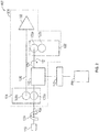
- FIG. 1 shows a pump system 100.
- the pump system 100 includes a multi-stage gear pump 101 including a main pump gear stage 102, an actuator gear stage 104, and a variable speed gearbox 110.
- the multi-stage gear pump 101 can provide a desired fuel flow through either a main pump gear stage 102 or an actuator gear stage 104 by adjusting the gear ratio of the variable speed gearbox 110.
- the use of the variable speed gearbox 110 allows for the actuator gear stage 104 to be driven at a different speed than the main pump gear stage 102 to allow for a desired amount of fuel to be delivered by both the main pump gear stage 102 and the actuator gear stage 104 on demand without any excess fuel pumping. Further, by reducing excess fuel pumping, heating of fuel can be reduced preventing varnish or coking of fuel within the fuel system and the aircraft.
- the pump stages 102, 104, 106 of the multi-stage gear pump 101 can be located in a common housing, while in other embodiments, the pump stages 102, 104, 106 can be located in separate housings and commonly driven or otherwise operatively connected.
- the multi-stage gear pump 101 receives rotational energy from a rotational device 119.
- the rotational device 119 can be a rotational drive from an engine, an engine gearbox or any other power source.
- the rotational device 119 can rotate the input shaft 122 at a first rotational speed 120.
- the first rotational speed 120 can vary in accordance with operational speed of the rotational device 119.
- the main pump gear stage 102 is driven by the rotational device 119.
- the main pump gear stage 102 includes a rotational input 103a and a rotational output 103b associated with the gears within the main pump gear stage 102.
- the main pump gear stage 102 supplies fuel to an engine of an aircraft.
- the main pump gear stage 102 speed and fuel output are related to the rotational speed of the main pump gear stage 102.
- the main pump gear stage 102 can receive rotational input from the rotational device 119 or any other suitable power source via the rotational input 103a.
- the rotational device 119 can rotate an input shaft 122 to rotate the rotational input 103a.
- the rotational input 103a is a pass through that allows the input shaft 122 to pass therethrough while driving the rotational input 103a. The pass through of the rotational input 103a can allow multiple devices to be rotated by the same shaft that passes therethrough.
- the main pump gear stage 102 can provide a rotational output via the rotational output 103b.
- rotation of the gears within the main pump gear stage 102 can drive the rotational output 103b.
- the rotational output 103b can rotate an output shaft, such as centrifugal boost shaft 126 to drive other rotating components, such as the centrifugal boost stage 106.
- the rotational output 103b can rotate at the same first rotational speed 120 that is received via the rotational input 103a.
- the rotational output 103b can have a relative gear ratio and drive the rotational output 103b at a different rotational speed. Therefore, in certain embodiments, the rotational output 103b can drive the centrifugal boost shaft 126 at a rotational speed varying from the first rotational speed 120.
- the rotational output 103b is a pass through that allows an output shaft to pass therethrough.
- the pass through of the rotational output 103b can allow multiple devices to be rotated by the same shaft that passes therethrough.
- the centrifugal boost stage 106 can receive rotational input from the rotational output 103b of the main pump gear stage 102.
- the rotational output 103a can rotate the centrifugal boost shaft 126 to rotate the centrifugal boost stage 106.
- the centrifugal boost stage 106 can be rotated at the same speed as the rotational output 103b.
- the centrifugal boost stage 106 is a pump to boost fuel pressure as needed.
- the rotational speed of the centrifugal boost pump 106 corresponds to the output of the centrifugal boost pump.
- the actuator gear stage 104 is driven by the variable speed gearbox 110.
- the actuator gear stage 104 includes a rotational input 105a and a rotational output 105b associated with the gears within the actuator gear stage 104.
- the actuator gear stage 104 supplies fuel to fueldraulic/hydraulic actuators within the aircraft.
- the actuator gear stage 104 speed and fuel output corresponds to the rotational speed of the actuator gear stage 104.
- the actuator gear stage 104 typically has lower fuel flow demands than the main fuel pump, and may have different fuel demands at different times.
- the actuator gear stage 104 can receive rotational input from the variable speed gearbox 110 or any other suitable power source via the rotational input 105a.
- the variable speed gearbox 110 can rotate an output shaft 124 to rotate the rotational input 105a.
- the rotational input 105a is a pass through that allows a shaft to pass therethrough while driving the rotational input 105a. The pass through of the rotational input 105a can allow multiple devices to be rotated by the same shaft that passes therethrough.
- the actuator gear stage 104 can provide a rotational output via the rotational output 105b.
- rotation of the gears within the actuator gear stage 104 can drive the rotational output 105b.
- the rotational output 105b can rotate an output shaft to drive other rotating components.
- the rotational output 105b can rotate at the same second rotational speed 121 that is received via the rotational input 105a.
- the rotational output 105b can have a relative gear ratio and drive the rotational output 105b at a different rotational speed. Therefore, in certain embodiments, the rotational output 105b can drive rotational components at a rotational speed varying from the second rotational speed 121.
- the rotational output 105b is a pass through that allows an output shaft to pass therethrough.
- the pass through of the rotational output 105b can allow multiple devices to be rotated by the same shaft that passes therethrough.
- variable speed gearbox 110 is connected to the input shaft 122 and the output shaft 124.
- the variable speed gearbox 110 receive a first rotational speed 120 of the input shaft 122 and can output and adjust the second rotational speed 121 of the output shaft 124.
- the second rotational speed 121 of the output shaft 124 can be adjusted by adjusting the gear ratio of the variable speed gearbox 110 in response to fuel demands.
- variable speed gearbox 110 can include any suitable combination of gears or other power transmission to variably adjust the second rotational speed 121 of the output shaft 124.
- the variable speed gearbox 110 can rotate the output shaft 124 at a second rotational speed 121 slower than the first rotational speed 120 of the input shaft 122 or faster than the first rotational speed 120 of the input shaft 122.
- the fuel flow output of the corresponding pump can be adjusted by varying the gear ratio of the variable speed gearbox 110.
- a controller 112 and an electronic engine controller 114 can work in conjunction to control the second rotational speed 121 of the output shaft 124 in response to fuel demands and other operating conditions.
- the electronic engine controller 114 can provide operational parameters including engine fuel demands, actuator flow demands, fuel temperature, fuel pressure, fuel flow rates, etc. to determine the current demand for the main pump gear stage 102 and the actuator gear stage 104.
- the electronic engine controller 114 can provide operational parameters to the controller 112 to control the variable speed gearbox 110 to provide a desired second rotational speed 121 of the output shaft 124.
- the output shaft 124 can be rotated at a lower second rotational speed 121.
- the controller 112 can further take into account the size and displacement of the pumps associated with the main pump gear stage 102 and the actuator pump stage 104.
- Advantageously, by varying the speed of the pump stages 102, 104 pumps can be sized based on different parameters and not peak demand.
- Advantageously pump speeds can be increased under demand and reduced under periods of low demand. Further, unnecessary heating of fuel can be reduced, reducing coking and varnishing of fuel.
- the actuator gear stage 104 is directly driven by the rotational device 119 and the main fuel pump 102 is driven by the variable speed gearbox 110.
- the centrifugal boost stage 106 is driven by the rotational output 105b of the actuator gear stage 104.
- the actuator gear stage 104 can be directly driven to provide greater flow from the actuator pump in applications that require high actuator fuel flow.
- the actuator gear stage 104 is directly driven by the rotational device 119 and the main fuel pump 102 is driven by the variable speed gearbox 110.
- the centrifugal boost stage 106 is driven by the rotational output 103b of the main pump gear stage 102.
- the actuator gear stage 104 can be directly driven to provide greater flow from the actuator pump in applications that require high actuator fuel flow.
- the centrifugal boost shaft 126 can be driven by the main pump gear stage 102 the multi-stage gear pump 101 can be packaged for a suitable location or application.
Landscapes
- Engineering & Computer Science (AREA)
- Mechanical Engineering (AREA)
- General Engineering & Computer Science (AREA)
- Aviation & Aerospace Engineering (AREA)
- Details And Applications Of Rotary Liquid Pumps (AREA)
- Rotary Pumps (AREA)
Abstract
Description
- The subject matter disclosed herein relates to gear driven fuel pumps, and more particularly, to gear driven fuel pumps for aircraft.
- Gear driven fuel pumps can be utilized within an aircraft to provide fuel pressure to engines and hydraulic actuators. Fuel pumps are designed and specified to provide a desired amount of fuel under peak demand conditions. Often, fuel pumps may pump excess fuel flow under lower demand conditions which may heat fuel.
- According to an embodiment, a multi-stage gear pump includes a first pump stage, a second pump stage, and a variable speed gearbox including an input and an output, wherein the input is rotationally coupled to the first pump stage and the input rotates at a first rotational speed, and the output is rotationally coupled to the second pump stage and rotates at a second rotational speed, wherein a variable gear ratio determines the second rotational speed relative to the first rotational speed.
- According to an embodiment, a method to operate a multi-stage gear pump includes providing a first pump stage, providing a second pump stage, rotationally coupling an input of a variable speed gearbox to the first pump stage, rotating the first pump stage at a first rotational speed, determining a second rotational speed relative to the first rotational speed via a variable gear ratio of the variable speed gearbox, rotationally coupling an output of the variable speed gearbox to the second pump stage, and rotating the second pump stage at the second rotational speed.
- Technical function of the embodiments described above includes a variable speed gearbox including an input and an output, wherein the input is rotationally coupled to the first pump stage and the input rotates at a first rotational speed, and the output is rotationally coupled to the second pump stage and rotates at a second rotational speed, wherein a variable gear ratio determines the second rotational speed relative to the first rotational speed.
- Other aspects, features, and techniques of the embodiments will become more apparent from the following description taken in conjunction with the drawings.
- The subject matter is particularly pointed out and distinctly claimed in the claims at the conclusion of the specification. The foregoing and other features, and advantages of the embodiments are apparent from the following detailed description taken in conjunction with the accompanying drawings in which like elements are numbered alike in the FIGURES:
-
FIG. 1 is a schematic view of an embodiment of a multi-stage gear pump; -
FIG. 2 is a schematic view of another embodiment of a multi-stage gear pump; and -
FIG. 3 is a schematic view of another embodiment of a multi-stage gear pump. - Referring to the drawings,
FIG. 1 shows apump system 100. In the illustrated embodiment, thepump system 100 includes amulti-stage gear pump 101 including a mainpump gear stage 102, anactuator gear stage 104, and avariable speed gearbox 110. In the illustrated embodiment, themulti-stage gear pump 101 can provide a desired fuel flow through either a mainpump gear stage 102 or anactuator gear stage 104 by adjusting the gear ratio of thevariable speed gearbox 110. Advantageously, the use of thevariable speed gearbox 110 allows for theactuator gear stage 104 to be driven at a different speed than the mainpump gear stage 102 to allow for a desired amount of fuel to be delivered by both the mainpump gear stage 102 and theactuator gear stage 104 on demand without any excess fuel pumping. Further, by reducing excess fuel pumping, heating of fuel can be reduced preventing varnish or coking of fuel within the fuel system and the aircraft. - In the illustrated embodiment, the
pump stages multi-stage gear pump 101 can be located in a common housing, while in other embodiments, thepump stages multi-stage gear pump 101 receives rotational energy from arotational device 119. Therotational device 119 can be a rotational drive from an engine, an engine gearbox or any other power source. Therotational device 119 can rotate theinput shaft 122 at a firstrotational speed 120. The firstrotational speed 120 can vary in accordance with operational speed of therotational device 119. - In the illustrated embodiment, the main
pump gear stage 102 is driven by therotational device 119. In the illustrated embodiment, the mainpump gear stage 102 includes arotational input 103a and arotational output 103b associated with the gears within the mainpump gear stage 102. The mainpump gear stage 102 supplies fuel to an engine of an aircraft. The mainpump gear stage 102 speed and fuel output are related to the rotational speed of the mainpump gear stage 102. - The main
pump gear stage 102 can receive rotational input from therotational device 119 or any other suitable power source via therotational input 103a. In the illustrated embodiment, therotational device 119 can rotate aninput shaft 122 to rotate therotational input 103a. In the illustrated embodiment, therotational input 103a is a pass through that allows theinput shaft 122 to pass therethrough while driving therotational input 103a. The pass through of therotational input 103a can allow multiple devices to be rotated by the same shaft that passes therethrough. - Further, the main
pump gear stage 102 can provide a rotational output via therotational output 103b. In the illustrated embodiment, rotation of the gears within the mainpump gear stage 102 can drive therotational output 103b. In the illustrated embodiment, therotational output 103b can rotate an output shaft, such ascentrifugal boost shaft 126 to drive other rotating components, such as thecentrifugal boost stage 106. In certain embodiments, therotational output 103b can rotate at the same firstrotational speed 120 that is received via therotational input 103a. - In other embodiments, the
rotational output 103b can have a relative gear ratio and drive therotational output 103b at a different rotational speed. Therefore, in certain embodiments, therotational output 103b can drive thecentrifugal boost shaft 126 at a rotational speed varying from the firstrotational speed 120. - In certain embodiments, the
rotational output 103b is a pass through that allows an output shaft to pass therethrough. The pass through of therotational output 103b can allow multiple devices to be rotated by the same shaft that passes therethrough. - The
centrifugal boost stage 106 can receive rotational input from therotational output 103b of the mainpump gear stage 102. Therotational output 103a can rotate thecentrifugal boost shaft 126 to rotate thecentrifugal boost stage 106. Thecentrifugal boost stage 106 can be rotated at the same speed as therotational output 103b. - In the illustrated embodiment, the
centrifugal boost stage 106 is a pump to boost fuel pressure as needed. In the illustrated embodiment, the rotational speed of thecentrifugal boost pump 106 corresponds to the output of the centrifugal boost pump. - In the illustrated embodiment, the
actuator gear stage 104 is driven by thevariable speed gearbox 110. In the illustrated embodiment, theactuator gear stage 104 includes arotational input 105a and arotational output 105b associated with the gears within theactuator gear stage 104. Theactuator gear stage 104 supplies fuel to fueldraulic/hydraulic actuators within the aircraft. Theactuator gear stage 104 speed and fuel output corresponds to the rotational speed of theactuator gear stage 104. In the illustrated embodiment, theactuator gear stage 104 typically has lower fuel flow demands than the main fuel pump, and may have different fuel demands at different times. - The
actuator gear stage 104 can receive rotational input from thevariable speed gearbox 110 or any other suitable power source via therotational input 105a. In the illustrated embodiment, thevariable speed gearbox 110 can rotate anoutput shaft 124 to rotate therotational input 105a. In the illustrated embodiment, therotational input 105a is a pass through that allows a shaft to pass therethrough while driving therotational input 105a. The pass through of therotational input 105a can allow multiple devices to be rotated by the same shaft that passes therethrough. - Further, the
actuator gear stage 104 can provide a rotational output via therotational output 105b. In the illustrated embodiment, rotation of the gears within theactuator gear stage 104 can drive therotational output 105b. In the illustrated embodiment, therotational output 105b can rotate an output shaft to drive other rotating components. In certain embodiments, therotational output 105b can rotate at the same secondrotational speed 121 that is received via therotational input 105a. - In other embodiments, the
rotational output 105b can have a relative gear ratio and drive therotational output 105b at a different rotational speed. Therefore, in certain embodiments, therotational output 105b can drive rotational components at a rotational speed varying from the secondrotational speed 121. - In certain embodiments, the
rotational output 105b is a pass through that allows an output shaft to pass therethrough. The pass through of therotational output 105b can allow multiple devices to be rotated by the same shaft that passes therethrough. - The
variable speed gearbox 110 is connected to theinput shaft 122 and theoutput shaft 124. In the illustrated embodiment, thevariable speed gearbox 110 receive a firstrotational speed 120 of theinput shaft 122 and can output and adjust the secondrotational speed 121 of theoutput shaft 124. Advantageously, the secondrotational speed 121 of theoutput shaft 124 can be adjusted by adjusting the gear ratio of thevariable speed gearbox 110 in response to fuel demands. - In the illustrated embodiment, the
variable speed gearbox 110 can include any suitable combination of gears or other power transmission to variably adjust the secondrotational speed 121 of theoutput shaft 124. In the illustrated embodiment, thevariable speed gearbox 110 can rotate theoutput shaft 124 at a secondrotational speed 121 slower than the firstrotational speed 120 of theinput shaft 122 or faster than the firstrotational speed 120 of theinput shaft 122. - Advantageously, since the second
rotational speed 121 of theoutput shaft 124 corresponds to the pump output of the pump rotationally connected to theoutput shaft 124, the fuel flow output of the corresponding pump can be adjusted by varying the gear ratio of thevariable speed gearbox 110. - In the illustrated embodiment a
controller 112 and anelectronic engine controller 114 can work in conjunction to control the secondrotational speed 121 of theoutput shaft 124 in response to fuel demands and other operating conditions. Theelectronic engine controller 114 can provide operational parameters including engine fuel demands, actuator flow demands, fuel temperature, fuel pressure, fuel flow rates, etc. to determine the current demand for the mainpump gear stage 102 and theactuator gear stage 104. Theelectronic engine controller 114 can provide operational parameters to thecontroller 112 to control thevariable speed gearbox 110 to provide a desired secondrotational speed 121 of theoutput shaft 124. - For example, during periods of low engine load and high actuator load, it may be desired to overdrive the
output shaft 124 to provide a higher secondrotational speed 121 relative to the firstrotational speed 120 of theinput shaft 122. Further, during periods of high engine load and low actuator load, theoutput shaft 124 can be rotated at a lower secondrotational speed 121. Thecontroller 112 can further take into account the size and displacement of the pumps associated with the mainpump gear stage 102 and theactuator pump stage 104. Advantageously, by varying the speed of the pump stages 102, 104 pumps can be sized based on different parameters and not peak demand. Advantageously pump speeds can be increased under demand and reduced under periods of low demand. Further, unnecessary heating of fuel can be reduced, reducing coking and varnishing of fuel. - Referring to
FIG. 2 , an alternative embodiment of themulti-stage gear pump 101 is shown. In the illustrated embodiment, theactuator gear stage 104 is directly driven by therotational device 119 and themain fuel pump 102 is driven by thevariable speed gearbox 110. In the illustrated embodiment, thecentrifugal boost stage 106 is driven by therotational output 105b of theactuator gear stage 104. Advantageously, theactuator gear stage 104 can be directly driven to provide greater flow from the actuator pump in applications that require high actuator fuel flow. - Referring to
FIG. 3 , an alternative embodiment of themulti-stage gear pump 101 is shown. In the illustrated embodiment, theactuator gear stage 104 is directly driven by therotational device 119 and themain fuel pump 102 is driven by thevariable speed gearbox 110. In the illustrated embodiment, thecentrifugal boost stage 106 is driven by therotational output 103b of the mainpump gear stage 102. Advantageously, theactuator gear stage 104 can be directly driven to provide greater flow from the actuator pump in applications that require high actuator fuel flow. Further, by arranging thecentrifugal boost shaft 126 to be driven by the mainpump gear stage 102 themulti-stage gear pump 101 can be packaged for a suitable location or application. - The terminology used herein is for the purpose of describing particular embodiments only and is not intended to be limiting of the embodiments. While the description of the present embodiments has been presented for purposes of illustration and description, it is not intended to be exhaustive or limited to the embodiments in the form disclosed. Many modifications, variations, alterations, substitutions or equivalent arrangement not hereto described will be apparent to those of ordinary skill in the art without departing from the scope of the invention as defined by the claims. Additionally, while various embodiments have been described, it is to be understood that aspects may include only some of the described embodiments. Accordingly, the embodiments are not to be seen as limited by the foregoing description, but are only limited by the scope of the appended claims.
Claims (15)
- A multi-stage gear pump, comprising:a first pump stage (102);a second pump stage (104); anda variable speed gearbox (110) including an input and an output, wherein the input is rotationally coupled to the first pump stage and the input rotates at a first rotational speed, and the output is rotationally coupled to the second pump stage and rotates at a second rotational speed, wherein a variable gear ratio determines the second rotational speed relative to the first rotational speed.
- The multi-stage gear pump of claim 1, further comprising a gearbox controller (112) to adjust the variable gear ratio.
- The multi-stage gear pump of claim 2, further comprising an electronic engine controller (114) to provide at least one operating parameter to the gearbox controller.
- The multi-stage gear pump of claim 3, wherein the gearbox controller (112) adjusts the variable gear ratio in response to the at least one operating parameter.
- The multi-stage gear pump of claim 1, wherein:the first pump stage is a main pump stage (102) or is an actuator pump stage, andthe second pump stage is a main pump stage or an actuator pump stage.
- The multi-stage gear pump of claim 1, further comprising a boost stage (106), wherein the boost stage is rotationally coupled to the first or the second pump stage.
- The multi-stage gear pump of claim 1, wherein the input of the variable speed gearbox is rotationally coupled to the first pump stage via an input shaft (122) and the output of the variable speed gearbox is rotationally coupled to the second pump stage via an output shaft (126).
- The multi-stage gear pump of claim 7, wherein the input shaft is rotationally coupled to a rotating device.
- The multi-stage gear pump of claim 4, wherein the boost stage is rotationally coupled to the first stage pump via a boost stage shaft (126).
- The multi-stage gear pump of claim 9, wherein the boost stage shaft is rotationally coupled to a first rotational output of the first stage pump.
- The multi-stage gear pump of claim 10, wherein the boost stage rotates at the first rotational speed.
- The multi-stage gear pump of claim 4, wherein the boost stage is rotationally coupled to the second stage pump via a boost stage shaft (126).
- The multi-stage gear pump of claim 12, wherein the boost stage shaft is rotationally coupled to a second rotational output of the second stage pump.
- The multi-stage gear pump of claim 13, wherein the boost stage rotates at the second rotational speed.
- A method to operate a multi-stage gear pump, comprising:providing a first pump stage;providing a second pump stage;rotationally coupling an input of a variable speed gearbox to the first pump stage;rotating the first pump stage at a first rotational speed;determining a second rotational speed relative to the first rotational speed via a variable gear ratio of the variable speed gearbox;rotationally coupling an output of the variable speed gearbox to the second pump stage; androtating the second pump stage at the second rotational speed.
Applications Claiming Priority (1)
| Application Number | Priority Date | Filing Date | Title |
|---|---|---|---|
| US15/332,040 US10428816B2 (en) | 2016-10-24 | 2016-10-24 | Variable speed multi-stage pump |
Publications (2)
| Publication Number | Publication Date |
|---|---|
| EP3312423A1 true EP3312423A1 (en) | 2018-04-25 |
| EP3312423B1 EP3312423B1 (en) | 2025-04-02 |
Family
ID=60186061
Family Applications (1)
| Application Number | Title | Priority Date | Filing Date |
|---|---|---|---|
| EP17198142.6A Active EP3312423B1 (en) | 2016-10-24 | 2017-10-24 | Variable speed multi-stage pump |
Country Status (2)
| Country | Link |
|---|---|
| US (1) | US10428816B2 (en) |
| EP (1) | EP3312423B1 (en) |
Families Citing this family (1)
| Publication number | Priority date | Publication date | Assignee | Title |
|---|---|---|---|---|
| US12281616B1 (en) * | 2023-12-20 | 2025-04-22 | Hamilton Sundstrand Corporation | Single variable displacement fuel systems with fuel oil coolers |
Citations (6)
| Publication number | Priority date | Publication date | Assignee | Title |
|---|---|---|---|---|
| US4420289A (en) * | 1980-06-19 | 1983-12-13 | Societe Nationale D'etude Et De Construction De Moteurs D'aviation, "S.N.E.C.M.A." | System for successively producing hydraulic fluid flows at staggered values |
| WO2002025115A1 (en) * | 2000-09-25 | 2002-03-28 | Compair Uk Limited | Multi-stage screw compressor |
| DE10104635A1 (en) * | 2001-02-02 | 2002-10-02 | Joma Hydromechanic Gmbh | Method for maintaining a constant output value, e.g. pressure, feed volume or capacity for vehicle oil pump, using rotational velocity transducer to adjust rotational speed of pump |
| US20110129359A1 (en) * | 2009-11-30 | 2011-06-02 | Caterpillar Inc. | Variable output pump |
| EP2562420A2 (en) * | 2011-08-26 | 2013-02-27 | Hamilton Sundstrand Corporation | Variable output pump |
| US20160025192A1 (en) * | 2012-05-08 | 2016-01-28 | Robert C. Kennedy | Variable Speed Drive System |
Family Cites Families (32)
| Publication number | Priority date | Publication date | Assignee | Title |
|---|---|---|---|---|
| US3953153A (en) | 1974-05-17 | 1976-04-27 | Sundstrand Corporation | Multiple displacement pump system and method |
| US4004412A (en) | 1974-12-20 | 1977-01-25 | Chandler Evans Inc. | Gas turbine engine fuel metering system |
| FR2571780B1 (en) | 1984-10-17 | 1987-01-02 | Snecma | FUEL DOSING DEVICE, FOR EXAMPLE FOR A GAS TURBINE |
| JPH05141272A (en) | 1991-11-22 | 1993-06-08 | Mitsubishi Heavy Ind Ltd | Fuel supply device for gas turbine vehicle |
| US5241826A (en) * | 1992-07-21 | 1993-09-07 | Stearns Charles F | Fixed geometry variable displacement pump system |
| US5326232A (en) * | 1993-04-20 | 1994-07-05 | General Motors Corporation | Two stage pump assembly with mechanical disconnect |
| KR100221591B1 (en) * | 1997-03-22 | 1999-09-15 | 토니헬 | Auxiliary pump structure |
| US6079198A (en) | 1998-04-29 | 2000-06-27 | General Electric Co. | Pressure compensated fuel delivery system for the combustors of turbomachinery |
| AUPP604398A0 (en) | 1998-09-18 | 1998-10-15 | Dean, Malcolm Leonard Stephen | Variable ratio multi-gear |
| DE10127196A1 (en) * | 2001-06-05 | 2002-12-12 | Rolls Royce Deutschland | Method for fuel supply and fuel supply system for an aircraft provided with at least one aircraft gas turbine |
| GB0408600D0 (en) * | 2004-04-19 | 2004-05-19 | Goodrich Control Sys Ltd | Pump assembly |
| US7524263B2 (en) | 2006-07-13 | 2009-04-28 | Caterpillar Inc. | Powertrain with powersplit pump input and method of use thereof |
| FR2934321B1 (en) * | 2008-07-25 | 2013-09-27 | Hispano Suiza Sa | CONTROL OF FUEL FLOW DRAINED IN A FUEL SYSTEM OF AN AIRCRAFT PROPELLED BY AN ENGINE. |
| GB0814025D0 (en) * | 2008-08-01 | 2008-09-10 | Goodrich Control Sys Ltd | Fuel pumping system |
| FR2950863B1 (en) * | 2009-10-06 | 2012-03-02 | Snecma | FUEL SUPPLY CIRCUIT FOR AN AIRCRAFT ENGINE |
| NZ582354A (en) | 2009-12-24 | 2010-05-28 | Swashpump Technologies Ltd | Non-rotating nutating plate pump with compound spherical bearing |
| US9151180B2 (en) | 2010-06-15 | 2015-10-06 | Hamilton Sundstrand Corporation | Lubrication driven gas turbine engine actuation system |
| US8893466B2 (en) * | 2011-03-18 | 2014-11-25 | Hamilton Sundstrand Corporation | Dual pump fuel flow system for a gas turbine engine and method of controlling |
| FR2983248B1 (en) * | 2011-11-29 | 2015-04-03 | Turbomeca | TURBOMACHINE COMPRISING AN ELECTRIC-ACTIVATED FUEL SUPPLY PUMP AND FUEL SUPPLY METHOD OF A TURBOMACHINE |
| CN202597086U (en) | 2012-04-23 | 2012-12-12 | 贾利春 | Mechanical rotor fluid capacity variable mechanism |
| US9827975B2 (en) | 2012-05-04 | 2017-11-28 | Ford Global Technologies, Llc | Methods and systems for improving transmission shifting |
| US20140150440A1 (en) | 2012-12-05 | 2014-06-05 | United Technologies Corporation | Gas turbine engine with a low speed spool driven pump arrangement |
| US9453463B2 (en) * | 2013-01-17 | 2016-09-27 | Honeywell International Inc. | High efficiency, high pressure gas turbine engine fuel supply system |
| DE102013203815A1 (en) | 2013-03-06 | 2014-09-11 | Robert Bosch Gmbh | Composite consisting of at least one expansion machine and a transmission |
| US8853878B1 (en) | 2013-05-14 | 2014-10-07 | Solar Turbines Inc. | Gas turbine engine with multiple load outputs |
| WO2015046133A1 (en) | 2013-09-25 | 2015-04-02 | 株式会社Ihi | Fuel system |
| US9574500B2 (en) | 2014-02-28 | 2017-02-21 | General Electric Company | Direct metering using a variable displacement vane pump |
| US9810158B2 (en) | 2014-04-01 | 2017-11-07 | The Boeing Company | Bleed air systems for use with aircraft and related methods |
| GB201407743D0 (en) | 2014-05-02 | 2014-06-18 | Rolls Royce Plc | Gas turbine engine fuel system |
| US9776728B2 (en) * | 2014-07-22 | 2017-10-03 | Hamilton Sundstrand Corporation | Dual-stage gear pump with reduced pressure ripple |
| GB201420635D0 (en) * | 2014-11-20 | 2015-01-07 | Rolls Royce Controls & Data Services Ltd | Fuel pumping unit |
| CN204610308U (en) | 2015-04-03 | 2015-09-02 | 南京王行航空附件维修工程有限公司 | Aircraft fuel pump the property test platform of centrifugal pump |
-
2016
- 2016-10-24 US US15/332,040 patent/US10428816B2/en active Active
-
2017
- 2017-10-24 EP EP17198142.6A patent/EP3312423B1/en active Active
Patent Citations (6)
| Publication number | Priority date | Publication date | Assignee | Title |
|---|---|---|---|---|
| US4420289A (en) * | 1980-06-19 | 1983-12-13 | Societe Nationale D'etude Et De Construction De Moteurs D'aviation, "S.N.E.C.M.A." | System for successively producing hydraulic fluid flows at staggered values |
| WO2002025115A1 (en) * | 2000-09-25 | 2002-03-28 | Compair Uk Limited | Multi-stage screw compressor |
| DE10104635A1 (en) * | 2001-02-02 | 2002-10-02 | Joma Hydromechanic Gmbh | Method for maintaining a constant output value, e.g. pressure, feed volume or capacity for vehicle oil pump, using rotational velocity transducer to adjust rotational speed of pump |
| US20110129359A1 (en) * | 2009-11-30 | 2011-06-02 | Caterpillar Inc. | Variable output pump |
| EP2562420A2 (en) * | 2011-08-26 | 2013-02-27 | Hamilton Sundstrand Corporation | Variable output pump |
| US20160025192A1 (en) * | 2012-05-08 | 2016-01-28 | Robert C. Kennedy | Variable Speed Drive System |
Also Published As
| Publication number | Publication date |
|---|---|
| US20180112660A1 (en) | 2018-04-26 |
| US10428816B2 (en) | 2019-10-01 |
| EP3312423B1 (en) | 2025-04-02 |
Similar Documents
| Publication | Publication Date | Title |
|---|---|---|
| US10094295B2 (en) | Gas turbine engine with transmission | |
| US8801394B2 (en) | System and method for driving a pump | |
| EP3023625B1 (en) | Engine driven-shaft driven compressor utilizing infinitely variable transmission | |
| US9777828B2 (en) | Fluid supply device | |
| CN102537328B (en) | Utilize the system and method for Hydraulic fluid lubricates variator components | |
| US10760654B2 (en) | Variable speed drive system | |
| US20220275794A1 (en) | Hydraulic fracturing pump apparatus and method for driving same | |
| CA2689235A1 (en) | Variable ratio transmission | |
| CN110234857A (en) | For the system to turbine supply fuel | |
| CN106121915A (en) | Blower fan hydraulic variable propeller system and method | |
| US10480505B2 (en) | Arrangement for specifying a pressure | |
| US10428816B2 (en) | Variable speed multi-stage pump | |
| US20230017990A1 (en) | Fuel delivery system for gas turbine engine | |
| CN110114596A (en) | Method and the driving system of machine for doing work with variable speed are driven for running driving system | |
| US20130303322A1 (en) | Variable Speed Drive System | |
| EP2550466A1 (en) | Variable speed hydraulic pump apparatus and method | |
| WO2018007567A2 (en) | Variable speed transmission with auxiliary driver and system using same | |
| CN110985292B (en) | Variable flow hydraulic circuit for wind turbine | |
| EP2618025B1 (en) | Variable range constant speed drive | |
| EP3736469A1 (en) | Lubrication system for a gearbox and wind turbine | |
| US20150010416A1 (en) | Controller for varying flow rate from fixed displacement pump | |
| EP3508757B1 (en) | Integrated drive generator and related method for replacing a governor drive gear therein | |
| JP2017067270A (en) | Oil pump drive system |
Legal Events
| Date | Code | Title | Description |
|---|---|---|---|
| PUAI | Public reference made under article 153(3) epc to a published international application that has entered the european phase |
Free format text: ORIGINAL CODE: 0009012 |
|
| STAA | Information on the status of an ep patent application or granted ep patent |
Free format text: STATUS: THE APPLICATION HAS BEEN PUBLISHED |
|
| AK | Designated contracting states |
Kind code of ref document: A1 Designated state(s): AL AT BE BG CH CY CZ DE DK EE ES FI FR GB GR HR HU IE IS IT LI LT LU LV MC MK MT NL NO PL PT RO RS SE SI SK SM TR |
|
| AX | Request for extension of the european patent |
Extension state: BA ME |
|
| STAA | Information on the status of an ep patent application or granted ep patent |
Free format text: STATUS: REQUEST FOR EXAMINATION WAS MADE |
|
| 17P | Request for examination filed |
Effective date: 20181025 |
|
| RBV | Designated contracting states (corrected) |
Designated state(s): AL AT BE BG CH CY CZ DE DK EE ES FI FR GB GR HR HU IE IS IT LI LT LU LV MC MK MT NL NO PL PT RO RS SE SI SK SM TR |
|
| STAA | Information on the status of an ep patent application or granted ep patent |
Free format text: STATUS: EXAMINATION IS IN PROGRESS |
|
| 17Q | First examination report despatched |
Effective date: 20200323 |
|
| GRAP | Despatch of communication of intention to grant a patent |
Free format text: ORIGINAL CODE: EPIDOSNIGR1 |
|
| STAA | Information on the status of an ep patent application or granted ep patent |
Free format text: STATUS: GRANT OF PATENT IS INTENDED |
|
| INTG | Intention to grant announced |
Effective date: 20241107 |
|
| GRAS | Grant fee paid |
Free format text: ORIGINAL CODE: EPIDOSNIGR3 |
|
| GRAA | (expected) grant |
Free format text: ORIGINAL CODE: 0009210 |
|
| STAA | Information on the status of an ep patent application or granted ep patent |
Free format text: STATUS: THE PATENT HAS BEEN GRANTED |
|
| AK | Designated contracting states |
Kind code of ref document: B1 Designated state(s): AL AT BE BG CH CY CZ DE DK EE ES FI FR GB GR HR HU IE IS IT LI LT LU LV MC MK MT NL NO PL PT RO RS SE SI SK SM TR |
|
| REG | Reference to a national code |
Ref country code: GB Ref legal event code: FG4D |
|
| REG | Reference to a national code |
Ref country code: CH Ref legal event code: EP |
|
| REG | Reference to a national code |
Ref country code: IE Ref legal event code: FG4D |
|
| REG | Reference to a national code |
Ref country code: DE Ref legal event code: R096 Ref document number: 602017088659 Country of ref document: DE |
|
| REG | Reference to a national code |
Ref country code: NL Ref legal event code: MP Effective date: 20250402 |
|
| PG25 | Lapsed in a contracting state [announced via postgrant information from national office to epo] |
Ref country code: NL Free format text: LAPSE BECAUSE OF FAILURE TO SUBMIT A TRANSLATION OF THE DESCRIPTION OR TO PAY THE FEE WITHIN THE PRESCRIBED TIME-LIMIT Effective date: 20250402 |
|
| REG | Reference to a national code |
Ref country code: AT Ref legal event code: MK05 Ref document number: 1781489 Country of ref document: AT Kind code of ref document: T Effective date: 20250402 |
|
| PG25 | Lapsed in a contracting state [announced via postgrant information from national office to epo] |
Ref country code: PT Free format text: LAPSE BECAUSE OF FAILURE TO SUBMIT A TRANSLATION OF THE DESCRIPTION OR TO PAY THE FEE WITHIN THE PRESCRIBED TIME-LIMIT Effective date: 20250804 Ref country code: ES Free format text: LAPSE BECAUSE OF FAILURE TO SUBMIT A TRANSLATION OF THE DESCRIPTION OR TO PAY THE FEE WITHIN THE PRESCRIBED TIME-LIMIT Effective date: 20250402 Ref country code: FI Free format text: LAPSE BECAUSE OF FAILURE TO SUBMIT A TRANSLATION OF THE DESCRIPTION OR TO PAY THE FEE WITHIN THE PRESCRIBED TIME-LIMIT Effective date: 20250402 |
|
| REG | Reference to a national code |
Ref country code: LT Ref legal event code: MG9D |
|
| PG25 | Lapsed in a contracting state [announced via postgrant information from national office to epo] |
Ref country code: GR Free format text: LAPSE BECAUSE OF FAILURE TO SUBMIT A TRANSLATION OF THE DESCRIPTION OR TO PAY THE FEE WITHIN THE PRESCRIBED TIME-LIMIT Effective date: 20250703 Ref country code: NO Free format text: LAPSE BECAUSE OF FAILURE TO SUBMIT A TRANSLATION OF THE DESCRIPTION OR TO PAY THE FEE WITHIN THE PRESCRIBED TIME-LIMIT Effective date: 20250702 |
|
| PG25 | Lapsed in a contracting state [announced via postgrant information from national office to epo] |
Ref country code: PL Free format text: LAPSE BECAUSE OF FAILURE TO SUBMIT A TRANSLATION OF THE DESCRIPTION OR TO PAY THE FEE WITHIN THE PRESCRIBED TIME-LIMIT Effective date: 20250402 |
|
| PG25 | Lapsed in a contracting state [announced via postgrant information from national office to epo] |
Ref country code: BG Free format text: LAPSE BECAUSE OF FAILURE TO SUBMIT A TRANSLATION OF THE DESCRIPTION OR TO PAY THE FEE WITHIN THE PRESCRIBED TIME-LIMIT Effective date: 20250402 |
|
| PGFP | Annual fee paid to national office [announced via postgrant information from national office to epo] |
Ref country code: GB Payment date: 20250923 Year of fee payment: 9 |
|
| PG25 | Lapsed in a contracting state [announced via postgrant information from national office to epo] |
Ref country code: HR Free format text: LAPSE BECAUSE OF FAILURE TO SUBMIT A TRANSLATION OF THE DESCRIPTION OR TO PAY THE FEE WITHIN THE PRESCRIBED TIME-LIMIT Effective date: 20250402 |
|
| PG25 | Lapsed in a contracting state [announced via postgrant information from national office to epo] |
Ref country code: AT Free format text: LAPSE BECAUSE OF FAILURE TO SUBMIT A TRANSLATION OF THE DESCRIPTION OR TO PAY THE FEE WITHIN THE PRESCRIBED TIME-LIMIT Effective date: 20250402 |
|
| PGFP | Annual fee paid to national office [announced via postgrant information from national office to epo] |
Ref country code: FR Payment date: 20250923 Year of fee payment: 9 |
|
| PG25 | Lapsed in a contracting state [announced via postgrant information from national office to epo] |
Ref country code: RS Free format text: LAPSE BECAUSE OF FAILURE TO SUBMIT A TRANSLATION OF THE DESCRIPTION OR TO PAY THE FEE WITHIN THE PRESCRIBED TIME-LIMIT Effective date: 20250702 |
|
| PG25 | Lapsed in a contracting state [announced via postgrant information from national office to epo] |
Ref country code: IS Free format text: LAPSE BECAUSE OF FAILURE TO SUBMIT A TRANSLATION OF THE DESCRIPTION OR TO PAY THE FEE WITHIN THE PRESCRIBED TIME-LIMIT Effective date: 20250802 |
|
| PG25 | Lapsed in a contracting state [announced via postgrant information from national office to epo] |
Ref country code: LV Free format text: LAPSE BECAUSE OF FAILURE TO SUBMIT A TRANSLATION OF THE DESCRIPTION OR TO PAY THE FEE WITHIN THE PRESCRIBED TIME-LIMIT Effective date: 20250402 |
|
| REG | Reference to a national code |
Ref country code: DE Ref legal event code: R097 Ref document number: 602017088659 Country of ref document: DE |
|
| PGFP | Annual fee paid to national office [announced via postgrant information from national office to epo] |
Ref country code: DE Payment date: 20250923 Year of fee payment: 9 |
|
| PG25 | Lapsed in a contracting state [announced via postgrant information from national office to epo] |
Ref country code: SM Free format text: LAPSE BECAUSE OF FAILURE TO SUBMIT A TRANSLATION OF THE DESCRIPTION OR TO PAY THE FEE WITHIN THE PRESCRIBED TIME-LIMIT Effective date: 20250402 Ref country code: DK Free format text: LAPSE BECAUSE OF FAILURE TO SUBMIT A TRANSLATION OF THE DESCRIPTION OR TO PAY THE FEE WITHIN THE PRESCRIBED TIME-LIMIT Effective date: 20250402 |
|
| PG25 | Lapsed in a contracting state [announced via postgrant information from national office to epo] |
Ref country code: CZ Free format text: LAPSE BECAUSE OF FAILURE TO SUBMIT A TRANSLATION OF THE DESCRIPTION OR TO PAY THE FEE WITHIN THE PRESCRIBED TIME-LIMIT Effective date: 20250402 |
|
| PG25 | Lapsed in a contracting state [announced via postgrant information from national office to epo] |
Ref country code: EE Free format text: LAPSE BECAUSE OF FAILURE TO SUBMIT A TRANSLATION OF THE DESCRIPTION OR TO PAY THE FEE WITHIN THE PRESCRIBED TIME-LIMIT Effective date: 20250402 |
|
| PG25 | Lapsed in a contracting state [announced via postgrant information from national office to epo] |
Ref country code: RO Free format text: LAPSE BECAUSE OF FAILURE TO SUBMIT A TRANSLATION OF THE DESCRIPTION OR TO PAY THE FEE WITHIN THE PRESCRIBED TIME-LIMIT Effective date: 20250402 Ref country code: SK Free format text: LAPSE BECAUSE OF FAILURE TO SUBMIT A TRANSLATION OF THE DESCRIPTION OR TO PAY THE FEE WITHIN THE PRESCRIBED TIME-LIMIT Effective date: 20250402 |
|
| PG25 | Lapsed in a contracting state [announced via postgrant information from national office to epo] |
Ref country code: IT Free format text: LAPSE BECAUSE OF FAILURE TO SUBMIT A TRANSLATION OF THE DESCRIPTION OR TO PAY THE FEE WITHIN THE PRESCRIBED TIME-LIMIT Effective date: 20250402 |
|
| PLBE | No opposition filed within time limit |
Free format text: ORIGINAL CODE: 0009261 |
|
| STAA | Information on the status of an ep patent application or granted ep patent |
Free format text: STATUS: NO OPPOSITION FILED WITHIN TIME LIMIT |
|
| REG | Reference to a national code |
Ref country code: CH Ref legal event code: L10 Free format text: ST27 STATUS EVENT CODE: U-0-0-L10-L00 (AS PROVIDED BY THE NATIONAL OFFICE) Effective date: 20260211 |
|
| 26N | No opposition filed |
Effective date: 20260105 |