EP3312403A2 - Tool kit and method for decoupling cross-fire tube assemblies in gas turbine engines - Google Patents
Tool kit and method for decoupling cross-fire tube assemblies in gas turbine engines Download PDFInfo
- Publication number
- EP3312403A2 EP3312403A2 EP17193833.5A EP17193833A EP3312403A2 EP 3312403 A2 EP3312403 A2 EP 3312403A2 EP 17193833 A EP17193833 A EP 17193833A EP 3312403 A2 EP3312403 A2 EP 3312403A2
- Authority
- EP
- European Patent Office
- Prior art keywords
- plunger
- liner
- lever arm
- base plate
- telescoping tube
- Prior art date
- Legal status (The legal status is an assumption and is not a legal conclusion. Google has not performed a legal analysis and makes no representation as to the accuracy of the status listed.)
- Granted
Links
Images



Classifications
-
- B—PERFORMING OPERATIONS; TRANSPORTING
- B25—HAND TOOLS; PORTABLE POWER-DRIVEN TOOLS; MANIPULATORS
- B25B—TOOLS OR BENCH DEVICES NOT OTHERWISE PROVIDED FOR, FOR FASTENING, CONNECTING, DISENGAGING, OR HOLDING
- B25B27/00—Hand tools, specially adapted for fitting together or separating parts or objects whether or not involving some deformation, not otherwise provided for
- B25B27/02—Hand tools, specially adapted for fitting together or separating parts or objects whether or not involving some deformation, not otherwise provided for for connecting objects by press fit or detaching same
-
- B—PERFORMING OPERATIONS; TRANSPORTING
- B25—HAND TOOLS; PORTABLE POWER-DRIVEN TOOLS; MANIPULATORS
- B25B—TOOLS OR BENCH DEVICES NOT OTHERWISE PROVIDED FOR, FOR FASTENING, CONNECTING, DISENGAGING, OR HOLDING
- B25B27/00—Hand tools, specially adapted for fitting together or separating parts or objects whether or not involving some deformation, not otherwise provided for
-
- F—MECHANICAL ENGINEERING; LIGHTING; HEATING; WEAPONS; BLASTING
- F23—COMBUSTION APPARATUS; COMBUSTION PROCESSES
- F23R—GENERATING COMBUSTION PRODUCTS OF HIGH PRESSURE OR HIGH VELOCITY, e.g. GAS-TURBINE COMBUSTION CHAMBERS
- F23R3/00—Continuous combustion chambers using liquid or gaseous fuel
- F23R3/42—Continuous combustion chambers using liquid or gaseous fuel characterised by the arrangement or form of the flame tubes or combustion chambers
- F23R3/46—Combustion chambers comprising an annular arrangement of several essentially tubular flame tubes within a common annular casing or within individual casings
- F23R3/48—Flame tube interconnectors, e.g. cross-over tubes
-
- F—MECHANICAL ENGINEERING; LIGHTING; HEATING; WEAPONS; BLASTING
- F01—MACHINES OR ENGINES IN GENERAL; ENGINE PLANTS IN GENERAL; STEAM ENGINES
- F01D—NON-POSITIVE DISPLACEMENT MACHINES OR ENGINES, e.g. STEAM TURBINES
- F01D25/00—Component parts, details, or accessories, not provided for in, or of interest apart from, other groups
- F01D25/28—Supporting or mounting arrangements, e.g. for turbine casing
- F01D25/285—Temporary support structures, e.g. for testing, assembling, installing, repairing; Assembly methods using such structures
-
- F—MECHANICAL ENGINEERING; LIGHTING; HEATING; WEAPONS; BLASTING
- F01—MACHINES OR ENGINES IN GENERAL; ENGINE PLANTS IN GENERAL; STEAM ENGINES
- F01D—NON-POSITIVE DISPLACEMENT MACHINES OR ENGINES, e.g. STEAM TURBINES
- F01D9/00—Stators
- F01D9/02—Nozzles; Nozzle boxes; Stator blades; Guide conduits, e.g. individual nozzles
- F01D9/023—Transition ducts between combustor cans and first stage of the turbine in gas-turbine engines; their cooling or sealings
-
- F—MECHANICAL ENGINEERING; LIGHTING; HEATING; WEAPONS; BLASTING
- F05—INDEXING SCHEMES RELATING TO ENGINES OR PUMPS IN VARIOUS SUBCLASSES OF CLASSES F01-F04
- F05D—INDEXING SCHEME FOR ASPECTS RELATING TO NON-POSITIVE-DISPLACEMENT MACHINES OR ENGINES, GAS-TURBINES OR JET-PROPULSION PLANTS
- F05D2230/00—Manufacture
- F05D2230/60—Assembly methods
- F05D2230/64—Assembly methods using positioning or alignment devices for aligning or centring, e.g. pins
-
- F—MECHANICAL ENGINEERING; LIGHTING; HEATING; WEAPONS; BLASTING
- F05—INDEXING SCHEMES RELATING TO ENGINES OR PUMPS IN VARIOUS SUBCLASSES OF CLASSES F01-F04
- F05D—INDEXING SCHEME FOR ASPECTS RELATING TO NON-POSITIVE-DISPLACEMENT MACHINES OR ENGINES, GAS-TURBINES OR JET-PROPULSION PLANTS
- F05D2230/00—Manufacture
- F05D2230/70—Disassembly methods
-
- F—MECHANICAL ENGINEERING; LIGHTING; HEATING; WEAPONS; BLASTING
- F05—INDEXING SCHEMES RELATING TO ENGINES OR PUMPS IN VARIOUS SUBCLASSES OF CLASSES F01-F04
- F05D—INDEXING SCHEME FOR ASPECTS RELATING TO NON-POSITIVE-DISPLACEMENT MACHINES OR ENGINES, GAS-TURBINES OR JET-PROPULSION PLANTS
- F05D2230/00—Manufacture
- F05D2230/72—Maintenance
-
- F—MECHANICAL ENGINEERING; LIGHTING; HEATING; WEAPONS; BLASTING
- F23—COMBUSTION APPARATUS; COMBUSTION PROCESSES
- F23R—GENERATING COMBUSTION PRODUCTS OF HIGH PRESSURE OR HIGH VELOCITY, e.g. GAS-TURBINE COMBUSTION CHAMBERS
- F23R2900/00—Special features of, or arrangements for continuous combustion chambers; Combustion processes therefor
- F23R2900/00017—Assembling combustion chamber liners or subparts
-
- F—MECHANICAL ENGINEERING; LIGHTING; HEATING; WEAPONS; BLASTING
- F23—COMBUSTION APPARATUS; COMBUSTION PROCESSES
- F23R—GENERATING COMBUSTION PRODUCTS OF HIGH PRESSURE OR HIGH VELOCITY, e.g. GAS-TURBINE COMBUSTION CHAMBERS
- F23R2900/00—Special features of, or arrangements for continuous combustion chambers; Combustion processes therefor
- F23R2900/00019—Repairing or maintaining combustion chamber liners or subparts
-
- F—MECHANICAL ENGINEERING; LIGHTING; HEATING; WEAPONS; BLASTING
- F23—COMBUSTION APPARATUS; COMBUSTION PROCESSES
- F23R—GENERATING COMBUSTION PRODUCTS OF HIGH PRESSURE OR HIGH VELOCITY, e.g. GAS-TURBINE COMBUSTION CHAMBERS
- F23R3/00—Continuous combustion chambers using liquid or gaseous fuel
Definitions
- the present disclosure generally relates to gas turbine engines. More particularly, the present disclosure relates to tool kits and methods for decoupling cross-fire tube assemblies in gas turbine engines.
- a gas turbine engine generally includes a compressor section, a combustion section, and a turbine section.
- the compressor section progressively increases the pressure of the air entering the gas turbine engine and supplies this compressed air to the combustion section.
- the compressed air and a fuel e.g., natural gas
- the combustion gases flow from the combustion section into the turbine section where they expand to produce mechanical rotational energy. For example, expansion of the combustion gases in the turbine section may rotate a rotor shaft connected, e.g., to a generator to produce electricity.
- the combustion section typically includes a plurality of annularly arranged combustors, each of which receives compressed air from the compressor section.
- Each combustor generally includes a combustor casing, a liner, and a flow sleeve.
- the combustor casing surrounds the combustor and contains the compressed air received from the compressor section therein.
- the liner is positioned within the combustor casing and defines at least a portion of the combustion chamber.
- the flow sleeve circumferentially surrounds at least a portion of the liner. As such, the flow sleeve and the liner collectively define an annular plenum therebetween through which the compressed air may flow before entering the combustion chamber.
- One or more fuel nozzles supply the fuel to each combustor for mixing with the compressed air therein. This fuel-air mixture flows into the combustion chamber where a spark plug or other ignition device may initiate combustion.
- each cross-fire tube assembly may propagate combustion between different combustion chambers. More specifically, each cross-fire tube assembly fluidly couples the combustion chamber in one combustor with the combustion chamber in an adjacent combustor. Accordingly, combustion in one combustion chamber may travel through the cross-fire tube assembly to ignite the fuel air mixture in an adjacent combustion chamber.
- the cross-fire tube assemblies In order to facilitate the aforementioned fluid communication, the cross-fire tube assemblies must connect to the liners defining the combustion chambers. Certain combustor maintenance activities (e.g., replacement of the liner) may require that the cross-fire tube assembly be decoupled from the liner. Nevertheless, conventional tools and methods for decoupling cross-fire tube assemblies may require removal of components from multiple combustors before use thereof.
- the present disclosure is directed to a tool kit for decoupling a telescoping tube from a liner of a combustor of a gas turbine engine.
- the tool kit includes a plunger assembly having a base plate, a post, a plunger, and a lever arm.
- the base plate couples to a combustor casing.
- the post extends outward from the base plate into a combustion chamber at least partially defined by the liner.
- the plunger slidably mounts to the post and is slidable between an extended position and a retracted position.
- the lever arm pivotably couples to the post and to the plunger. Pivoting the lever arm in a first direction slides the plunger to the extended position to decouple the telescoping tube from the liner.
- a retaining clip couples to the combustor casing and extends into an annular plenum at least partially defined between the liner and the combustor casing.
- the retaining clip defines a notch that receives the telescoping tube after the plunger assembly decouples the telescoping tube from the liner.
- a system for decoupling a telescoping tube from a liner of a gas turbine engine includes a liner that at least partially defines a combustion chamber.
- a combustor casing surrounds at least a portion of the liner and is spaced apart from the liner.
- the combustor casing and the liner at least partially define an annular plenum therebetween.
- a telescoping tube extends through the combustor casing and couples to the liner.
- a plunger assembly includes a base plate, a post, a plunger, and a lever arm.
- the base plate couples to the combustor casing.
- the post extends outward from the base plate into the combustion chamber.
- the plunger is positioned in the combustion chamber and slidably mounts to the post.
- the plunger aligns with the telescoping tube and is slidable between an extended position and a retracted position.
- the lever arm pivotably couples to the post and to the plunger. Pivoting the lever arm in a first direction slides the plunger into contact with the telescoping tube and into the extended position to decouple the telescoping tube from the liner.
- a retaining clip couples to the combustor casing and extends into the annular plenum. The retaining clip defines a notch that receives the telescoping tube after the plunger assembly decouples the telescoping tube from the liner.
- a further aspect of the present disclosure is directed to a method for decoupling a telescoping tube from a liner of a combustor of a gas turbine engine.
- the method includes inserting a plunger assembly partially into a combustion chamber defined by the liner.
- the plunger assembly includes a base plate, a post extending outward from the base plate into the combustion chamber, a plunger slidably mounted to the post and aligned with the telescoping tube, and a lever arm pivotably coupled to the post and to the plunger.
- the base plate is coupled to the combustor casing.
- the lever arm is pivoted in a first direction to slide the plunger into contact with the telescoping tube and into an extended position to decouple the telescoping tube from the liner.
- the lever arm is locked after the plunger is in the extended position.
- a retaining clip is inserted into an annular plenum defined between the liner and the combustor casing such that a notch defined by the retaining clip receives the telescoping tube to retain the telescoping tube in a decoupled position.
- the retaining clip is coupled to the combustor casing.
- FIG. 1 schematically illustrates an exemplary gas turbine engine 10.
- the gas turbine engine 10 includes an inlet section 12, a compressor 14, one or more combustors 16, a turbine 18, and an exhaust section 20.
- the compressor 14 and turbine 18 may be coupled by a shaft 22, which may be a single shaft or a plurality of shaft segments coupled together.
- the gas turbine engine 10 produces mechanical rotational energy, which may, e.g., be used to generate electricity. More specifically, air 24 enters the inlet section 12 of the gas turbine engine 10.
- the inlet section 12 may include various filters, cooling coils, moisture separators, and/or other devices to purify and otherwise condition the air 24.
- the air 24 flows into the compressor 14, where it is progressively compressed to provide compressed air 26 to each of the combustors 16.
- the compressed air 26 in each of the combustors 16 mixes with a fuel 28.
- the resulting fuel-air mixture burns in each combustor 16 to produce high temperature and high pressure combustion gases 30.
- the combustion gases 30 flow through the turbine 18, which extracts kinetic and/or thermal energy therefrom. This energy extraction rotates the shaft 22, thereby creating mechanical rotational energy for powering the compressor 14 and/or generating electricity.
- the combustion gases 30 exit the gas turbine engine 10 through the exhaust section 20.
- the exhaust section 20 may include, for example, a heat recovery steam generator (not shown) for cleaning and extracting additional heat from the combustion gases 30 prior to release to the environment.
- Some embodiments of the gas turbine engine 10 include multiple combustors 16.
- the combustors 16 may be annularly-arranged can-type combustors.
- FIG. 2 illustrates an exemplary embodiment of one of the combustors 16.
- the combustor 16 is a can-type combustor. More specifically, the combustor 16 includes a combustor casing 32 that couples to a compressor discharge casing 34. The combustor casing 32 circumferentially encloses at least a portion of the combustor 16. As such, the combustor casing 32 and/or the compressor discharge casing 34 contain the compressed air 26 entering the combustor 16 from the compressor 14. The combustor 16 also includes an end cover 36 that couples to the combustor casing 32. As shown in FIG.
- the combustor casing 32 and end cover 36 collectively define a head end 38 in the combustor 16.
- One or more fuel nozzles 40 may be arranged in the head end 38 to supply fuel 28, diluent, and/or other additives to a combustion chamber 44 located downstream from the head end 38.
- a liner 42 positioned downstream of the head end 38 defines the combustion chamber 44 where the fuel-air mixture is burned.
- a transition duct 46 positioned downstream from the liner 42 couples the combustor 16 to the turbine 18. As such, the liner 42 and the transition duct 46 at least partially define a hot gas path 48 through the combustor 16 for routing the combustion gases 30 to the turbine 18.
- the combustor 16 may have different configurations in other embodiments.
- the embodiment of the combustor 16 shown in FIG. 2 includes an annular plenum 50. More particularly, a flow sleeve 52 may circumferentially surround a portion of the liner 42. Similarly, an impingement sleeve 54 defining one or more flow apertures 56 extending therethrough may circumferentially surround at least a portion of the transition duct 46. In this respect, the liner 42, the transition duct 46, the flow sleeve 52, and impingement sleeve 54 collectively define the annular plenum 50. In the embodiment shown in FIG. 2 , the flow sleeve 52 terminates before reaching the head end 38.
- the liner 42 and the combustor casing 32 define a portion of the annular plenum 50 positioned between the flow sleeve 52 and the head end 38.
- the compressed air 26 from the compressor 14 may enter the annular plenum 50 through the one or more flow apertures 56 in the impingement sleeve 54.
- the compressed air 26 flows through the annular plenum 50 to the head end 38, it convectively cools the transition duct 46 and the liner 42.
- the compressed air 26 Upon reaching the head end 38, the compressed air 26 reverses direction and flows through the fuel nozzles 40 and into the combustion chamber 44.
- the gas turbine engine 10 includes one or more cross-fire tube assemblies 58.
- Each of the cross-fire tube assemblies 58 fluidly couples an adjacent pair of the combustors 16 to permit combustion to propagate therebetween.
- one of the cross-fire tube assemblies 58 fluidly couples a first combustor 16A and an adjacent second combustor 16B.
- combustion in, e.g., the first combustor 16A may travel through the cross-fire tube assembly 58 to the second combustor 16B.
- the combustion may travel through the cross-fire tube assembly 58 from the second combustor 16B to the first combustor 16A as well.
- every one of the combustors 16 in the gas turbine engine 10 need not have a spark plug or other ignition device (not shown).
- the gas turbine engine 10 may include as many or as few cross-fire tube assemblies 58 as is necessary or desired.
- the crossfire tube assembly 58 generally includes an extendable or telescoping tube 60. More specifically, the telescoping tube 60 includes a first side surface 62 positioned at a first end 64 thereof and a second side surface 66 positioned at second end 68 thereof. As shown, the telescoping tube 60 includes a first tube segment 70 and a second tube segment 72 in sliding engagement with the first tube segment 70. The first tube segment 70 couples to the liner 42 of the first combustor 16A, and the second tube segment 72 couples to the liner 42 of the second combustor 16B.
- the telescoping tube 60 may have more than two tube segments in other embodiments. Although generally illustrated as a cylindrical tube, the telescoping tube 60 may have any suitable geometric cross-section.
- the telescoping tube 60 defines a telescoping tube passage 74.
- the telescoping tube passage 74 is in fluid communication with the combustion chamber 44 of the first combustor 16A and the combustion chamber 44 of the second combustor 16B.
- the first tube segment 70 extends through the combustor casing 32 and the liner 42 of the first combustor 16A.
- the second tube segment 72 extends through the combustor casing 32 and the liner 42 of the second combustor 16B.
- the telescoping tube 60 has a narrowest inner diameter 76 and an outer diameter 78. As shown in FIG. 3 , the outer diameter 78 is measured at the first end 64 and/or the second end 68 of the telescoping tube 60.
- the telescoping tube 60 includes one or more flanges 80.
- the one or more flanges 80 locate the first and/or second tubes segments 70, 72 against the combustor casings 32 of the first and/or the second combustors 16A, 16B.
- the liners 42 of the first and/or the second combustors 16A, 16B may include a boss 82.
- the first end 64 and/or the second end 68 of the telescoping tube 60 may slide inside or outside of the bosses 82 to provide the aforementioned fluid communication between the telescoping tube 60 and the combustion chambers 44. Furthermore, the bosses 82 reduce or prevent the compressed air 26 from leaking into the telescoping tube 60 and/or the combustion gases 30 from leaking out of the telescoping tube 60.
- the cross-fire tube assembly 58 includes a bias 84 that biases the first and the second tube segments 70, 72 apart.
- the bias 84 may positively seat the one or more flanges 80 against the combustor casings 32 of the first and the second combustors 16A, 16B.
- the bias 84 couples the telescoping tube 60 to the liners 42 of the first and the second combustors 16A, 16B.
- the bias 84 adjusts a length 86 of the telescoping tube 60 to accommodate varying distances and/or vibrations between the first and the second combustors 16A, 16B.
- the bias 84 is a compression spring that circumferentially surrounds at least a portion of the second tube segment 72. Nevertheless, the bias 84 may circumferentially surround at least a portion of the first tube segment 70 in other embodiments. Moreover, the bias 84 may be a tension spring, torsion spring, clutch, or other suitable biasing device in alternate embodiments.
- the cross-fire tube assembly 58 may include a bellows 88 that circumferentially surrounds at least a portion of the telescoping tube 60.
- the bellows 88 may welded or otherwise connected to the combustor casings 32 of the first and second combustor 16A, 16B to provide an expandable barrier therebetween.
- Some embodiments of the cross-fire tube assembly 58 may not include the bellows 88.
- FIGS. 4-10 illustrate various components of a tool kit 100 for decoupling the telescoping tube 60 of the cross-fire tube assembly 58 from the liner 42, the first combustor 16A, the second combustor 16B, and/or any other combustor 16 in the gas turbine engine 10.
- the tool kit 100 includes a plunger assembly 102, one or more retaining clips 104, and a plurality of connectors 106.
- FIGS. 4-7 illustrate the plunger assembly 102 in greater detail. More specifically, the plunger assembly 102 includes a base plate 108 having a first end 110 spaced apart from a second end 112. Furthermore, the base plate 108 includes a top surface 114, a bottom surface 116 spaced apart from the top surface 114, a front surface 118, and a rear surface 120 spaced apart from the front surface 118. The base plate 108 defines a notch 122 positioned between the first and second ends 110, 112 thereof. In particular, the notch 122 extends inwardly from the rear surface 120 of the base plate 108 toward the front surface 118 of the base plate 108. The notch 122 also extends through the entire thickness of the base plate 108.
- the notch 122 extends through the top and bottom surfaces 114, 116 of the base plate 108.
- the base plate 108 is arcuate. Nevertheless, the base plate 108 may have any suitable shape.
- the plunger assembly 102 includes at least one pin block 124 coupled to the top surface 114 of the base plate 108.
- one pin block 124 is positioned on each side of and adjacent to the notch 122.
- the pin blocks 124 may extend past the rear surface 120 of the base plate 108 such that portions of the pin blocks 124 are not supported by the base plate 108 in some embodiments. In other embodiments, however, only one pin block 124 may couple to the top surface 114 of the base plate 108 and/or the pin blocks 124 may be entirely supported by the base plate 108.
- Each of the pin blocks 124 defines a first pin block aperture 126 and a second pin block aperture 128 spaced apart from the first pin block aperture 126.
- each pin block 124 unsupported by the base plate 108 may define the first pin block aperture 126 in certain embodiments.
- the plunger assembly 102 includes two pin blocks 124 (i.e., one pin block 124 on each side of the notch 122 as shown in FIGS. 4-6 ), the first pin block apertures 126 of each of the pin blocks 124 are coaxial.
- the second pin block apertures 128 of each of the pin blocks 124 are also coaxial.
- the pin blocks 124 may also define additional pin block apertures (not shown) located between the first and the second pin block apertures 126, 128 in some embodiments.
- One or more connectors 106 couple to each of the first and second ends 110, 112 of the base plate 108. In the embodiment shown in FIGS. 4-6 , one connector 106 is positioned at each of the first and second ends 110, 112. Although, two or more connectors 106 may be positioned at each of the first and second ends 110, 112 in other embodiments. The connectors 106 will be discussed in greater detail below.
- a pair of handles 132 extends outwardly from the top surface 114 of the base plate 108.
- each handle 132 is positioned between the notch 122 and one of the connectors 106.
- zero, one, three, or more handles 132 may extend outwardly from the top surface 114 of the base plate 108.
- the handles 132 may have any suitable size, shape, and/or configuration.
- the plunger assembly 102 also includes a post 134 that extends outward from the bottom surface 116 of the base plate 108.
- the post 134 includes a first side plate 136 and a second side plate 138 spaced apart from the first side plate 136.
- the first and second side plates 136, 138 extend outwardly from the bottom surface 116 of the base plate 108 and are positioned adjacent to the notch 122.
- the first side plate 136 is positioned between the notch 122 and the first end 110 of the base plate 108.
- the second side plate 138 is positioned between the notch 122 and the second end 112 of the base plate 108.
- a bushing plate 140 extends between and couples to the first and the second side plates 136, 138.
- the bushing plate 140 is spaced apart from the base plate 108.
- the bushing plate 140 defines a bushing plate aperture 142 extending therethrough.
- a bushing 144 may be positioned into the bushing plate aperture 142.
- a pivot shaft 146 extends between and couples the first and the second side plates 136, 138. As best shown in FIG. 4 , the pivot shaft 146 may be positioned between the bushing plate 140 and the base plate 108. Furthermore, the pivot shaft 146 may be positioned between the first and second pin block apertures 126, 128.
- the post 134 may have other suitable configurations as well.
- the plunger assembly 102 further includes a plunger 148 having an outer surface 150, a side surface 152, and a plunger diameter 154.
- the plunger diameter 154 is greater than the narrowest inner diameter 76 of the telescoping tube 60 and less than the outer diameter 78 of the telescoping tube 60.
- a boss 156 having a boss diameter 158 extends outwardly from the outer surface 150 of the plunger 148.
- the boss diameter 158 is less than the plunger diameter 154 and the narrowest inner diameter 76 of the telescoping tube 60.
- the plunger 148 is slidably received in the bushing plate aperture 142. In this respect, the plunger 148 is slidable between a retracted position shown in FIG.
- the plunger 148 is in the retracted position when it extends outwardly (i.e., in the direction extending from the rear surface 120 of the base plate 108 to the front surface 118 of the base plate 108) from the bushing plate 140 a minimum distance. Conversely, the plunger 148 is in the extended position when it extends outwardly from the bushing plate 140 a maximum distance.
- the plunger 148 and the boss 156 may have any suitable geometric cross-sections.
- the plunger assembly 102 includes a lever arm 160 pivotably coupled to the post 134 and the plunger 148 for actuating the plunger 148. More specifically, the lever arm 160 includes a first end 162 and a second end 164 spaced apart from the first end 162. As shown in FIGS. 4-6 , the first end 162 of the lever arm 160 is generally positioned above the top surface 114 of the base plate 108. Conversely, the second end 164 of the lever arm 160 is positioned below the bottom surface 116 of the base plate 108 and generally aligned with the plunger 148 as will be discussed in greater detail below. The first end 162 of the lever arm 160 may optionally include a handle or grip 166 to facilitate user manipulation thereof.
- the lever arm 160 may include a fork 168 positioned at the second end 164 thereof that pivotably couples to the plunger 148. More specifically, the fork 168 includes a first fork arm 170 spaced apart from a second fork arm 172. In this respect, the first and the second fork arms 170, 172 define a slot 174 therebetween that receives a portion of the plunger 148. The first and the second fork arms 170, 172 respectively define a first fork arm aperture 176 and a second fork arm aperture 178 that is coaxial with the first fork arm aperture 176.
- a pivot pin 180 may extend through the first and second arm apertures 174, 176 to pivotably couple the lever arm 160 and the plunger 148. Some embodiments may not include the fork 168.
- the lever arm 160 defines a pivot aperture 182 extending therethrough. As best shown in FIGS. 5 and 8 , the pivot aperture 182 is located between the first and the second ends 162, 164 of the lever arm 160 and generally aligned with the pivot shaft 146 extending between the first and second side plates 136, 138. As such, the pivot shaft 146 is positioned in the pivot aperture 182 to pivotably couple the lever arm 160 and the post 134. In the embodiment shown in FIGS. 5 and 8 , a sleeve 184 extends outwardly from opposing sides of the lever arm 160 and further defines the pivot aperture 182. Although, some embodiments may not include the sleeves 184.
- the lever arm 160 defines a locking aperture 186 extending therethrough and positioned between the first end 162 and the pivot aperture 182.
- a locking pin 188 may be positioned in the locking aperture 186 and either the first pin block apertures 126 or the second pin block apertures 128 to prevent movement of the lever arm 160.
- the locking aperture 186 is coaxial with the first pin block aperture 126 when the lever arm 160 is aligned with the first pin block aperture 126.
- the locking aperture 186 is coaxial with the second pin block aperture 128 when the lever arm 160 is aligned with the second pin block aperture 128.
- the tool kit 100 also includes the one or more retaining clips 104.
- the tool kit 100 includes at least as many retaining clips 104 as there are cross-fire tube assemblies 58 that couple to the combustor 16.
- the tool kit 100 will include at least two retaining clips 104.
- each retaining clip 104 holds the telescoping tube 60 of one of the cross-fire tube assemblies 58 in a decoupled position. The decoupled position is where the telescoping tube 60 is not in contact with or connected to the liner 42.
- the tool kit 100 may include more retaining clips 104 than there are cross-fire tube assemblies 58 that couple to the combustor 16 to provide, e.g., spare retaining clips 104.
- each retaining clip 104 includes a base plate 190 having a first end 192 spaced apart from a second end 194.
- the base plate 190 also includes a top surface 196, a bottom surface 198 spaced apart from the top surface 196, a front surface 200, and a rear surface 202 spaced apart from the front surface 200.
- a clip arm 204 extends outwardly from the bottom surface 198 of the base plate 190.
- the clip arm 204 includes a front surface 206, a rear surface 208 spaced apart from the front surface 206, and a bottom surface 210 spaced apart from the bottom surface 198 of the base plate 190. As shown in FIG.
- the front and rear surfaces 206, 208 of the clip arm 204 are generally parallel to and spaced apart from the front surface 200 of the base plate 190.
- the clip arm 204 defines a notch 212 having a notch width 214 greater than the plunger diameter 154.
- the notch 212 extends inwardly from the bottom surface 210 of the clip arm 204 and through the entire thickness of the clip arm 204. That is, the notch 212 extends through the front and rear surfaces 206, 208 of the clip arm 204.
- One or more connectors 106 couple to each of the first and second ends 192, 194 of the base plate 190. In the embodiment shown in FIG. 9 , one connector 106 is positioned at each of the first and second ends 192, 194. Although, two or more connectors 106 may be positioned at each of the first and second ends 192, 194 in other embodiments.
- FIGS. 10 and 11 illustrate one embodiment of the connectors 106, which may couple to the base plate 108 of the plunger assembly 102 and/or the base plate 190 of the retaining clips 104.
- each connector 106 includes a stud 216, a knob 218, and a pin 220.
- the stud 216 includes a first end 222 spaced apart from a threaded second end 224.
- the first end 222 includes a circumferential boss 226 extending outwardly therefrom.
- the threaded second end 224 defines an aperture 228 extending therethrough.
- the knob 218 defines an aperture 230 extending therethrough and a threaded cavity 232 oriented generally perpendicularly to the aperture 230.
- the aperture 230 extends through the threaded cavity 232.
- the pin 220 may be a spring pin or any other suitable pin.
- the connector 106 may include other components or have other configurations.
- FIG. 11 illustrates the connector 106 assembled and coupled to the base plate 108 of the plunger assembly 102.
- the stud 216 extends through an aperture 234 defined by the base plate 108 such that the circumferential boss 226 is positioned below the bottom surface 116 of the base plate 108 and the threaded second end 224 is positioned above the top surface 114 of the base plate 108.
- the circumferential boss 226 is wider than the aperture 234 in the base plate 108.
- the knob 218 threadingly couples to the threaded second end 224 of the stud 216.
- the threaded second end 224 of the stud 216 is threadingly received in the threaded cavity 232 of the knob 218 such that the aperture 228 in the stud 216 is coaxial with the aperture 230 in the knob 218.
- the pin 220 is positioned in the apertures 228, 230, thereby coupling the knob 218 and the stud 216.
- a washer 236 may be positioned between the knob 218 and the top surface 114 of the base plate 108.
- the connector 106 may couple to the base plate 190 of the retaining clips 104 in same manner.
- FIG. 12 is a flowchart illustrating an exemplary method 300 for using the tool kit 100 to decouple the telescoping tube 60 from the liner 42 in accordance with the embodiments disclosed herein.
- FIGS. 13-19 illustrate various steps of the method 300.
- step 302 the head end 38 of the combustor 16 or a portion thereof is removed to provide access to the combustion chamber 44 and a flange 90 of the combustor casing 32.
- step 304 the lever arm 160 of the plunger assembly 102 is pivoted in a second direction to slide the plunger 148 into the retracted position ( FIG. 4 ).
- pivoting the first end 162 of the lever arm 160 toward the front surface 118 of the base plate 108 slides the plunger 148 into the retracted position.
- the lever arm 160 may be manipulated differently to place the plunger 148 in the retracted position in other embodiments of the plunger assembly 102.
- the locking pin 188 may be inserted into the second pin block apertures 128 and the locking aperture 186 of the lever arm 160 to lock the plunger 148 in the retracted position.
- the plunger 148 should be in the retracted position before installation of the plunger assembly 102 in the combustion chamber 44.
- the plunger assembly 102 is partially inserted into the combustion chamber 44 in step 306 and coupled to the combustor casing 32 in step 308.
- FIGS. 13 and 14 illustrate the positioning of the plunger assembly 102 upon completion of step 308.
- a pair of the connectors 106 couples the first and second ends 110, 112 of the base plate 108 to the flange 90 of the combustor casing 32.
- the arcuate shape of the base plate 108 permits the base plate 108 to extend inwardly from the combustor casing 32.
- a portion of the base plate 108 is positioned over the combustion chamber 44 when the plunger assembly 102 is coupled to the combustor casing 32.
- the post 134 extends down into the combustion chamber 44 such that the plunger 148 is aligned (i.e., coaxial) with the telescoping tube 60.
- step 310 the lever arm 160 of the plunger assembly 102 is pivoted in the first direction to slide the plunger 148 into the extended position ( FIG. 6 ).
- the locking pin 188 may need to be removed from the second pin block apertures 128 and the locking aperture 186 of the lever arm 160 to permit movement of the lever arm 160 from the retracted position to the extended position.
- pivoting the first end 162 of the lever arm 160 toward the rear surface 120 of the base plate 108 pushes the plunger 148 into the extended position.
- the lever arm 160 may be manipulated differently to place the plunger 148 in the extended position in other embodiments of the plunger assembly 102.
- the locking pin 188 may be inserted into the first pin block apertures 126 and the locking aperture 186 of the lever arm 160 to lock the plunger 148 in the extended position.
- Step 310 Moving the plunger 148 into the extended position in accordance with step 310 decouples the telescoping tube 60 from the liner 42 of the combustor 16.
- the outer surface 150 ( FIG. 6 ) of the plunger 148 contacts the first side surface 62 ( FIG. 3 ) of the telescoping tube 60.
- the boss 156 extending outward from the plunger 148 is positioned in the telescoping tube passage 74 to prevent the plunger 148 from sliding off of the telescoping tube 60.
- the plunger 148 compresses the bias 84 and slides the first tube segment 70 relative to the second tube segment 72. Once the plunger 148 reaches the extended position, the first tube segment 70 has moved out of contact with the liner 42, thereby decoupling the telescoping tube 60 from the liner 42.
- step 312 the position of the lever arm 160 is locked after the plunger 148 is moved to the extended position.
- the locking aperture 186 of the lever arm 160 is aligned (i.e., coaxial) with the first pin block apertures 126 once the plunger 148 is in the extended position.
- the locking pin 188 is positioned in the locking aperture 186 and the first pin block apertures 126 to prevent movement of the lever arm 160 relative to the base plate 108.
- the retaining clip 104 is partially inserted into the annular plenum 50 in step 314 and coupled to the combustor casing 32 in step 316.
- FIGS. 17 and 18 illustrate the positioning of the retaining clip 104 upon completion of step 316.
- a pair of the connectors 106 couples the first and second ends 192, 194 of the base plate 190 to the flange 90 of the combustor casing 32.
- a portion of the base plate 108 is positioned over the annular plenum 50 when the retaining clip 104 is coupled to the combustor casing 32.
- the clip arm 204 extends down into the annular plenum 50 such that a portion of the plunger 148 is positioned in the notch 212.
- the lever arm 160 is unlocked in step 318 and pivoted in the second direction to slide the plunger into the retracted position in step 320.
- the locking pin 188 is removed from the locking aperture 186 of the lever arm 160 and the first pin block apertures 126 to unlock the lever arm 160.
- the locking pin 188 is inserted into the second pin block apertures 128 and the locking aperture 186 of the lever arm 160 to lock the plunger 148 in the retracted position.
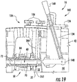
- the retaining clip 104 Upon completion of step 318, the retaining clip 104 holds the telescoping tube 60 in the decoupled position. That is, the retaining clip 104 prevents the bias 84 from pushing the first tube segment 70 back into contact with the liner 42. More specifically, the bias 84 pushes the first tube segment 70 toward the liner 42 once the plunger 148 moves to the retracted position in accordance with step 320. In this respect, the retaining clip 104 catches the first tube segment 70 of the telescoping tube 60, thereby preventing further movement toward the liner 42. As shown in FIG. 19 , a portion of the first tube segment 70 is positioned in the notch 212 upon completion of step 320.
- the plunger assembly 102 is decoupled from the flange 90 of the combustor casing 32.
- the plunger assembly 102 is decoupled from the flange 90 by removing the connectors 106.
- the plunger assembly 102 is removed from the combustion chamber 44 of the combustor 106.
- Steps 308-322 may be repeated for any additional cross-fire tube assemblies 58 coupled to the combustor 16.
- additional retaining clips 104 may be necessary to hold additional telescoping tubes 60 in the decoupled position.
- the same plunger assembly 102 may be used to decouple each cross-fire tube assembly 58.
- various maintenance operations may performed on the combustor 16. For example, the liner 42 may optionally be removed from the combustor 16 in step 326.
- the tool kit 100 and the method 300 disclosed herein decouple the telescoping tube 60 of the cross-fire tube assembly 58 from the liner 42 of the combustor 16.
- the tool kit 100 and the method 300 only require the removal of the head end 38 or a portion the head end 38 of the combustor 16 containing the liner 42 from which the telescoping tube 60 is to be decoupled.
- the head ends of adjacent combustors need not be removed in order to use of the tool kit 100 or the method 300 to decouple cross-fire tube assemblies 58.
Landscapes
- Engineering & Computer Science (AREA)
- Mechanical Engineering (AREA)
- General Engineering & Computer Science (AREA)
- Chemical & Material Sciences (AREA)
- Combustion & Propulsion (AREA)
- Turbine Rotor Nozzle Sealing (AREA)
- Quick-Acting Or Multi-Walled Pipe Joints (AREA)
- Gas Burners (AREA)
Abstract
Description
- The present disclosure generally relates to gas turbine engines. More particularly, the present disclosure relates to tool kits and methods for decoupling cross-fire tube assemblies in gas turbine engines.
- A gas turbine engine generally includes a compressor section, a combustion section, and a turbine section. The compressor section progressively increases the pressure of the air entering the gas turbine engine and supplies this compressed air to the combustion section. The compressed air and a fuel (e.g., natural gas) mix within the combustion section before burning in one or more combustion chambers to generate high pressure and high temperature combustion gases. The combustion gases flow from the combustion section into the turbine section where they expand to produce mechanical rotational energy. For example, expansion of the combustion gases in the turbine section may rotate a rotor shaft connected, e.g., to a generator to produce electricity.
- The combustion section typically includes a plurality of annularly arranged combustors, each of which receives compressed air from the compressor section. Each combustor generally includes a combustor casing, a liner, and a flow sleeve. The combustor casing surrounds the combustor and contains the compressed air received from the compressor section therein. The liner is positioned within the combustor casing and defines at least a portion of the combustion chamber. The flow sleeve circumferentially surrounds at least a portion of the liner. As such, the flow sleeve and the liner collectively define an annular plenum therebetween through which the compressed air may flow before entering the combustion chamber. One or more fuel nozzles supply the fuel to each combustor for mixing with the compressed air therein. This fuel-air mixture flows into the combustion chamber where a spark plug or other ignition device may initiate combustion.
- In certain configurations having multiple combustors in the combustion section, only some of the combustors may include the spark plug or other ignition device. In this respect, one or more cross-fire tube assemblies may propagate combustion between different combustion chambers. More specifically, each cross-fire tube assembly fluidly couples the combustion chamber in one combustor with the combustion chamber in an adjacent combustor. Accordingly, combustion in one combustion chamber may travel through the cross-fire tube assembly to ignite the fuel air mixture in an adjacent combustion chamber.
- In order to facilitate the aforementioned fluid communication, the cross-fire tube assemblies must connect to the liners defining the combustion chambers. Certain combustor maintenance activities (e.g., replacement of the liner) may require that the cross-fire tube assembly be decoupled from the liner. Nevertheless, conventional tools and methods for decoupling cross-fire tube assemblies may require removal of components from multiple combustors before use thereof.
- Aspects and advantages of the technology will be set forth in part in the following description, or may be obvious from the description, or may be learned through practice of the technology.
- In one aspect, the present disclosure is directed to a tool kit for decoupling a telescoping tube from a liner of a combustor of a gas turbine engine. The tool kit includes a plunger assembly having a base plate, a post, a plunger, and a lever arm. The base plate couples to a combustor casing. The post extends outward from the base plate into a combustion chamber at least partially defined by the liner. The plunger slidably mounts to the post and is slidable between an extended position and a retracted position. The lever arm pivotably couples to the post and to the plunger. Pivoting the lever arm in a first direction slides the plunger to the extended position to decouple the telescoping tube from the liner. A retaining clip couples to the combustor casing and extends into an annular plenum at least partially defined between the liner and the combustor casing. The retaining clip defines a notch that receives the telescoping tube after the plunger assembly decouples the telescoping tube from the liner.
- Another aspect of the present disclosure is directed to a system for decoupling a telescoping tube from a liner of a gas turbine engine. The system includes a liner that at least partially defines a combustion chamber. A combustor casing surrounds at least a portion of the liner and is spaced apart from the liner. The combustor casing and the liner at least partially define an annular plenum therebetween. A telescoping tube extends through the combustor casing and couples to the liner. A plunger assembly includes a base plate, a post, a plunger, and a lever arm. The base plate couples to the combustor casing. The post extends outward from the base plate into the combustion chamber. The plunger is positioned in the combustion chamber and slidably mounts to the post. The plunger aligns with the telescoping tube and is slidable between an extended position and a retracted position. The lever arm pivotably couples to the post and to the plunger. Pivoting the lever arm in a first direction slides the plunger into contact with the telescoping tube and into the extended position to decouple the telescoping tube from the liner. A retaining clip couples to the combustor casing and extends into the annular plenum. The retaining clip defines a notch that receives the telescoping tube after the plunger assembly decouples the telescoping tube from the liner.
- A further aspect of the present disclosure is directed to a method for decoupling a telescoping tube from a liner of a combustor of a gas turbine engine. The method includes inserting a plunger assembly partially into a combustion chamber defined by the liner. The plunger assembly includes a base plate, a post extending outward from the base plate into the combustion chamber, a plunger slidably mounted to the post and aligned with the telescoping tube, and a lever arm pivotably coupled to the post and to the plunger. The base plate is coupled to the combustor casing. The lever arm is pivoted in a first direction to slide the plunger into contact with the telescoping tube and into an extended position to decouple the telescoping tube from the liner. The lever arm is locked after the plunger is in the extended position. A retaining clip is inserted into an annular plenum defined between the liner and the combustor casing such that a notch defined by the retaining clip receives the telescoping tube to retain the telescoping tube in a decoupled position. The retaining clip is coupled to the combustor casing.
- These and other features, aspects and advantages of the present technology will become better understood with reference to the following description and appended claims. The accompanying drawings, which are incorporated in and constitute a part of this specification, illustrate embodiments of the technology and, together with the description, serve to explain the principles of the technology.
- A full and enabling disclosure of the present technology, including the best mode thereof, directed to one of ordinary skill in the art, is set forth in the specification, which makes reference to the appended FIGS., in which:
-
FIG. 1 is a functional block diagram of an exemplary gas turbine engine that may incorporate various embodiments of the present disclosure; -
FIG. 2 is a simplified cross-sectional side view of an exemplary combustor that may incorporate various embodiments of the present disclosure; -
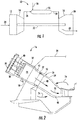
FIG. 3 is a cross-sectional side view of an exemplary cross-fire tube assembly, illustrating a telescoping tube coupled to a liner of the combustor; -
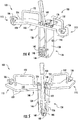
FIG. 4 is a front perspective view of a plunger assembly, which may be part of a tool kit for decoupling the telescoping tube in accordance with the embodiments disclosed herein; -
FIG. 5 is a rear perspective view of the plunger assembly, further illustrating various features thereof; -
FIG. 6 is a front perspective view of the plunger assembly similar toFIG. 4 , illustrating a plunger in an extended position; -
FIG. 7 is an enlarged front view of a post of the plunger assembly, illustrating a bushing plate; -
FIG. 8 is a cross-sectional view of a lever arm of the plunger assembly, illustrating the various features thereof; -
FIG. 9 is a perspective view of a retaining clip, which may be part of the tool kit for decoupling the telescoping tube in accordance with the embodiments disclosed herein; -
FIG. 10 is a perspective view of a connector, which may be part of the tool kit for decoupling the telescoping tube in accordance with the embodiments disclosed herein; -
FIG. 11 is a cross-sectional view of the connector taken generally about line 11-11 inFIG. 10 , further illustrating the features thereof; -
FIG. 12 is a flow chart illustrating a method for using the tool kit to decouple the telescoping tube in accordance with the embodiments disclosed herein; -
FIG. 13 is a perspective view of a portion of the combustor, illustrating the plunger assembly coupled to a combustor casing; -
FIG. 14 is a cross-sectional view of the combustor, illustrating the positioning of the plunger assembly in a combustion chamber; -
FIG. 15 is a cross-sectional view of the combustor, illustrating the telescoping tube decoupled from the liner; -
FIG. 16 is a perspective view of a portion of the combustor, illustrating a locking pin locking the position of the lever arm; -
FIG. 17 is a perspective view of a portion of the combustor, illustrating the retaining clip coupled to the combustor casing; -
FIG. 18 is a cross-sectional view of a portion of the combustor, illustrating the positioning of the retaining clip in an annular plenum between the combustor casing and the liner; and -
FIG. 19 is a cross-sectional view of a portion of the combustor, illustrating the retaining clip holding the telescoping tube in a decoupled position. - Repeat use of reference characters in the present specification and drawings is intended to represent the same or analogous features or elements of the present technology.
- Reference will now be made in detail to present embodiments of the technology, one or more examples of which are illustrated in the accompanying drawings. The detailed description uses numerical and letter designations to refer to features in the drawings. Like or similar designations in the drawings and description have been used to refer to like or similar parts of the technology. As used herein, the terms "first", "second", and "third" may be used interchangeably to distinguish one component from another and are not intended to signify location or importance of the individual components. The terms "upstream" and "downstream" refer to the relative direction with respect to fluid flow in a fluid pathway. For example, "upstream" refers to the direction from which the fluid flows, and "downstream" refers to the direction to which the fluid flows.
- Each example is provided by way of explanation of the technology, not limitation of the technology. In fact, it will be apparent to those skilled in the art that modifications and variations can be made in the present technology without departing from the scope or spirit thereof. For instance, features illustrated or described as part of one embodiment may be used on another embodiment to yield a still further embodiment. Thus, it is intended that the present technology covers such modifications and variations as come within the scope of the appended claims and their equivalents. Although an industrial or land-based gas turbine is shown and described herein, the present technology as shown and described herein is not limited to a land-based and/or industrial gas turbine unless otherwise specified in the claims. For example, the technology as described herein may be used in any type of turbine including, but not limited to, aviation gas turbines (e.g., turbofans, etc.), steam turbines, and marine gas turbines.
- Now referring to the drawings, wherein identical numerals indicate the same elements throughout the figures,
FIG. 1 schematically illustrates an exemplarygas turbine engine 10. As depicted therein, thegas turbine engine 10 includes aninlet section 12, acompressor 14, one ormore combustors 16, aturbine 18, and anexhaust section 20. Thecompressor 14 andturbine 18 may be coupled by ashaft 22, which may be a single shaft or a plurality of shaft segments coupled together. - During operation, the
gas turbine engine 10 produces mechanical rotational energy, which may, e.g., be used to generate electricity. More specifically,air 24 enters theinlet section 12 of thegas turbine engine 10. In some embodiments, theinlet section 12 may include various filters, cooling coils, moisture separators, and/or other devices to purify and otherwise condition theair 24. From theinlet section 12, theair 24 flows into thecompressor 14, where it is progressively compressed to providecompressed air 26 to each of thecombustors 16. Thecompressed air 26 in each of thecombustors 16 mixes with afuel 28. The resulting fuel-air mixture burns in each combustor 16 to produce high temperature and highpressure combustion gases 30. From thecombustors 16, thecombustion gases 30 flow through theturbine 18, which extracts kinetic and/or thermal energy therefrom. This energy extraction rotates theshaft 22, thereby creating mechanical rotational energy for powering thecompressor 14 and/or generating electricity. Thecombustion gases 30 exit thegas turbine engine 10 through theexhaust section 20. In some embodiments, theexhaust section 20 may include, for example, a heat recovery steam generator (not shown) for cleaning and extracting additional heat from thecombustion gases 30 prior to release to the environment. - Some embodiments of the
gas turbine engine 10 includemultiple combustors 16. In such embodiments, thecombustors 16 may be annularly-arranged can-type combustors. -
FIG. 2 illustrates an exemplary embodiment of one of thecombustors 16. In the embodiment depicted therein, thecombustor 16 is a can-type combustor. More specifically, thecombustor 16 includes acombustor casing 32 that couples to acompressor discharge casing 34. Thecombustor casing 32 circumferentially encloses at least a portion of thecombustor 16. As such, thecombustor casing 32 and/or thecompressor discharge casing 34 contain thecompressed air 26 entering the combustor 16 from thecompressor 14. Thecombustor 16 also includes anend cover 36 that couples to thecombustor casing 32. As shown inFIG. 2 , thecombustor casing 32 and end cover 36 collectively define ahead end 38 in thecombustor 16. One ormore fuel nozzles 40 may be arranged in thehead end 38 to supplyfuel 28, diluent, and/or other additives to acombustion chamber 44 located downstream from thehead end 38. Aliner 42 positioned downstream of thehead end 38 defines thecombustion chamber 44 where the fuel-air mixture is burned. Atransition duct 46 positioned downstream from theliner 42 couples thecombustor 16 to theturbine 18. As such, theliner 42 and thetransition duct 46 at least partially define ahot gas path 48 through thecombustor 16 for routing thecombustion gases 30 to theturbine 18. Although, thecombustor 16 may have different configurations in other embodiments. - The embodiment of the
combustor 16 shown inFIG. 2 includes anannular plenum 50. More particularly, aflow sleeve 52 may circumferentially surround a portion of theliner 42. Similarly, animpingement sleeve 54 defining one ormore flow apertures 56 extending therethrough may circumferentially surround at least a portion of thetransition duct 46. In this respect, theliner 42, thetransition duct 46, theflow sleeve 52, andimpingement sleeve 54 collectively define theannular plenum 50. In the embodiment shown inFIG. 2 , theflow sleeve 52 terminates before reaching thehead end 38. As such, theliner 42 and thecombustor casing 32 define a portion of theannular plenum 50 positioned between theflow sleeve 52 and thehead end 38. In operation, thecompressed air 26 from thecompressor 14 may enter theannular plenum 50 through the one ormore flow apertures 56 in theimpingement sleeve 54. As thecompressed air 26 flows through theannular plenum 50 to thehead end 38, it convectively cools thetransition duct 46 and theliner 42. Upon reaching thehead end 38, thecompressed air 26 reverses direction and flows through thefuel nozzles 40 and into thecombustion chamber 44. - As shown in
FIG. 2 , thegas turbine engine 10 includes one or morecross-fire tube assemblies 58. Each of thecross-fire tube assemblies 58 fluidly couples an adjacent pair of thecombustors 16 to permit combustion to propagate therebetween. In the embodiment shown inFIG. 3 , for example, one of thecross-fire tube assemblies 58 fluidly couples afirst combustor 16A and an adjacentsecond combustor 16B. In this respect, combustion in, e.g., thefirst combustor 16A may travel through thecross-fire tube assembly 58 to thesecond combustor 16B. Nevertheless, the combustion may travel through thecross-fire tube assembly 58 from thesecond combustor 16B to thefirst combustor 16A as well. As such, every one of thecombustors 16 in thegas turbine engine 10 need not have a spark plug or other ignition device (not shown). Thegas turbine engine 10 may include as many or as fewcross-fire tube assemblies 58 as is necessary or desired. - As shown in
FIG. 3 , thecrossfire tube assembly 58 generally includes an extendable ortelescoping tube 60. More specifically, thetelescoping tube 60 includes afirst side surface 62 positioned at afirst end 64 thereof and asecond side surface 66 positioned atsecond end 68 thereof. As shown, thetelescoping tube 60 includes afirst tube segment 70 and asecond tube segment 72 in sliding engagement with thefirst tube segment 70. Thefirst tube segment 70 couples to theliner 42 of thefirst combustor 16A, and thesecond tube segment 72 couples to theliner 42 of thesecond combustor 16B. Thetelescoping tube 60 may have more than two tube segments in other embodiments. Although generally illustrated as a cylindrical tube, thetelescoping tube 60 may have any suitable geometric cross-section. - In order to propagate combustion between the first and the
second combustors telescoping tube 60 defines atelescoping tube passage 74. In particular, thetelescoping tube passage 74 is in fluid communication with thecombustion chamber 44 of thefirst combustor 16A and thecombustion chamber 44 of thesecond combustor 16B. As such, thefirst tube segment 70 extends through thecombustor casing 32 and theliner 42 of thefirst combustor 16A. Similarly, thesecond tube segment 72 extends through thecombustor casing 32 and theliner 42 of thesecond combustor 16B. Thetelescoping tube 60 has a narrowestinner diameter 76 and anouter diameter 78. As shown inFIG. 3 , theouter diameter 78 is measured at thefirst end 64 and/or thesecond end 68 of thetelescoping tube 60. - Various flanges, bosses, or other detents that locate the
telescoping tube 60 relative to the first andsecond combustors FIG. 3 , for example, thetelescoping tube 60 includes one ormore flanges 80. Specifically, the one ormore flanges 80 locate the first and/orsecond tubes segments combustor casings 32 of the first and/or thesecond combustors liners 42 of the first and/or thesecond combustors boss 82. Thefirst end 64 and/or thesecond end 68 of thetelescoping tube 60 may slide inside or outside of thebosses 82 to provide the aforementioned fluid communication between the telescopingtube 60 and thecombustion chambers 44. Furthermore, thebosses 82 reduce or prevent thecompressed air 26 from leaking into thetelescoping tube 60 and/or thecombustion gases 30 from leaking out of thetelescoping tube 60. - In the embodiment shown in
FIG. 3 , thecross-fire tube assembly 58 includes abias 84 that biases the first and thesecond tube segments bias 84 may positively seat the one ormore flanges 80 against thecombustor casings 32 of the first and thesecond combustors bias 84 couples thetelescoping tube 60 to theliners 42 of the first and thesecond combustors bias 84 adjusts alength 86 of thetelescoping tube 60 to accommodate varying distances and/or vibrations between the first and thesecond combustors FIG. 3 , thebias 84 is a compression spring that circumferentially surrounds at least a portion of thesecond tube segment 72. Nevertheless, thebias 84 may circumferentially surround at least a portion of thefirst tube segment 70 in other embodiments. Moreover, thebias 84 may be a tension spring, torsion spring, clutch, or other suitable biasing device in alternate embodiments. - In the embodiment shown in
FIG. 3 , thecross-fire tube assembly 58 may include abellows 88 that circumferentially surrounds at least a portion of thetelescoping tube 60. The bellows 88 may welded or otherwise connected to thecombustor casings 32 of the first andsecond combustor cross-fire tube assembly 58 may not include thebellows 88. -
FIGS. 4-10 illustrate various components of atool kit 100 for decoupling thetelescoping tube 60 of thecross-fire tube assembly 58 from theliner 42, thefirst combustor 16A, thesecond combustor 16B, and/or anyother combustor 16 in thegas turbine engine 10. In general, thetool kit 100 includes aplunger assembly 102, one or more retaining clips 104, and a plurality ofconnectors 106. -
FIGS. 4-7 illustrate theplunger assembly 102 in greater detail. More specifically, theplunger assembly 102 includes abase plate 108 having afirst end 110 spaced apart from asecond end 112. Furthermore, thebase plate 108 includes atop surface 114, abottom surface 116 spaced apart from thetop surface 114, afront surface 118, and arear surface 120 spaced apart from thefront surface 118. Thebase plate 108 defines anotch 122 positioned between the first and second ends 110, 112 thereof. In particular, thenotch 122 extends inwardly from therear surface 120 of thebase plate 108 toward thefront surface 118 of thebase plate 108. Thenotch 122 also extends through the entire thickness of thebase plate 108. That is, thenotch 122 extends through the top andbottom surfaces base plate 108. In the embodiment shown inFIGS. 4-6 , thebase plate 108 is arcuate. Nevertheless, thebase plate 108 may have any suitable shape. - The
plunger assembly 102 includes at least onepin block 124 coupled to thetop surface 114 of thebase plate 108. In the embodiment shown inFIGS. 4-6 , onepin block 124 is positioned on each side of and adjacent to thenotch 122. Furthermore, the pin blocks 124 may extend past therear surface 120 of thebase plate 108 such that portions of the pin blocks 124 are not supported by thebase plate 108 in some embodiments. In other embodiments, however, only onepin block 124 may couple to thetop surface 114 of thebase plate 108 and/or the pin blocks 124 may be entirely supported by thebase plate 108. Each of the pin blocks 124 defines a firstpin block aperture 126 and a secondpin block aperture 128 spaced apart from the firstpin block aperture 126. As best shown inFIG. 6 , the portion of each pin block 124 unsupported by thebase plate 108, if present, may define the firstpin block aperture 126 in certain embodiments. If theplunger assembly 102 includes two pin blocks 124 (i.e., onepin block 124 on each side of thenotch 122 as shown inFIGS. 4-6 ), the firstpin block apertures 126 of each of the pin blocks 124 are coaxial. Similarly, the secondpin block apertures 128 of each of the pin blocks 124 are also coaxial. The pin blocks 124 may also define additional pin block apertures (not shown) located between the first and the secondpin block apertures - One or
more connectors 106 couple to each of the first and second ends 110, 112 of thebase plate 108. In the embodiment shown inFIGS. 4-6 , oneconnector 106 is positioned at each of the first and second ends 110, 112. Although, two ormore connectors 106 may be positioned at each of the first and second ends 110, 112 in other embodiments. Theconnectors 106 will be discussed in greater detail below. - In the embodiment shown in
FIGS. 4-6 , a pair ofhandles 132 extends outwardly from thetop surface 114 of thebase plate 108. In particular, each handle 132 is positioned between thenotch 122 and one of theconnectors 106. In other embodiments, zero, one, three, ormore handles 132 may extend outwardly from thetop surface 114 of thebase plate 108. Thehandles 132 may have any suitable size, shape, and/or configuration. - The
plunger assembly 102 also includes apost 134 that extends outward from thebottom surface 116 of thebase plate 108. As shown inFIGS. 4-7 , thepost 134 includes afirst side plate 136 and asecond side plate 138 spaced apart from thefirst side plate 136. The first andsecond side plates bottom surface 116 of thebase plate 108 and are positioned adjacent to thenotch 122. As shown inFIGS. 4 and6 , thefirst side plate 136 is positioned between thenotch 122 and thefirst end 110 of thebase plate 108. Conversely, thesecond side plate 138 is positioned between thenotch 122 and thesecond end 112 of thebase plate 108. Abushing plate 140 extends between and couples to the first and thesecond side plates bushing plate 140 is spaced apart from thebase plate 108. As shown inFIG. 7 , thebushing plate 140 defines abushing plate aperture 142 extending therethrough. In certain embodiments, abushing 144 may be positioned into thebushing plate aperture 142. Apivot shaft 146 extends between and couples the first and thesecond side plates FIG. 4 , thepivot shaft 146 may be positioned between thebushing plate 140 and thebase plate 108. Furthermore, thepivot shaft 146 may be positioned between the first and secondpin block apertures post 134 may have other suitable configurations as well. - The
plunger assembly 102 further includes aplunger 148 having anouter surface 150, aside surface 152, and aplunger diameter 154. Theplunger diameter 154 is greater than the narrowestinner diameter 76 of thetelescoping tube 60 and less than theouter diameter 78 of thetelescoping tube 60. Aboss 156 having aboss diameter 158 extends outwardly from theouter surface 150 of theplunger 148. Theboss diameter 158 is less than theplunger diameter 154 and the narrowestinner diameter 76 of thetelescoping tube 60. As shown inFIGS. 4-6 , theplunger 148 is slidably received in thebushing plate aperture 142. In this respect, theplunger 148 is slidable between a retracted position shown inFIG. 4 and an extended position shown inFIG. 6 . Theplunger 148 is in the retracted position when it extends outwardly (i.e., in the direction extending from therear surface 120 of thebase plate 108 to thefront surface 118 of the base plate 108) from the bushing plate 140 a minimum distance. Conversely, theplunger 148 is in the extended position when it extends outwardly from the bushing plate 140 a maximum distance. Although generally illustrated having a circular cross-section, theplunger 148 and theboss 156 may have any suitable geometric cross-sections. - The
plunger assembly 102 includes alever arm 160 pivotably coupled to thepost 134 and theplunger 148 for actuating theplunger 148. More specifically, thelever arm 160 includes afirst end 162 and asecond end 164 spaced apart from thefirst end 162. As shown inFIGS. 4-6 , thefirst end 162 of thelever arm 160 is generally positioned above thetop surface 114 of thebase plate 108. Conversely, thesecond end 164 of thelever arm 160 is positioned below thebottom surface 116 of thebase plate 108 and generally aligned with theplunger 148 as will be discussed in greater detail below. Thefirst end 162 of thelever arm 160 may optionally include a handle orgrip 166 to facilitate user manipulation thereof. - The
lever arm 160 may include afork 168 positioned at thesecond end 164 thereof that pivotably couples to theplunger 148. More specifically, thefork 168 includes afirst fork arm 170 spaced apart from asecond fork arm 172. In this respect, the first and thesecond fork arms slot 174 therebetween that receives a portion of theplunger 148. The first and thesecond fork arms fork arm aperture 176 and a secondfork arm aperture 178 that is coaxial with the firstfork arm aperture 176. Apivot pin 180 may extend through the first andsecond arm apertures lever arm 160 and theplunger 148. Some embodiments may not include thefork 168. - The
lever arm 160 defines apivot aperture 182 extending therethrough. As best shown inFIGS. 5 and8 , thepivot aperture 182 is located between the first and the second ends 162, 164 of thelever arm 160 and generally aligned with thepivot shaft 146 extending between the first andsecond side plates pivot shaft 146 is positioned in thepivot aperture 182 to pivotably couple thelever arm 160 and thepost 134. In the embodiment shown inFIGS. 5 and8 , asleeve 184 extends outwardly from opposing sides of thelever arm 160 and further defines thepivot aperture 182. Although, some embodiments may not include thesleeves 184. - Furthermore, the
lever arm 160 defines a lockingaperture 186 extending therethrough and positioned between thefirst end 162 and thepivot aperture 182. A lockingpin 188 may be positioned in the lockingaperture 186 and either the firstpin block apertures 126 or the secondpin block apertures 128 to prevent movement of thelever arm 160. In this respect, the lockingaperture 186 is coaxial with the firstpin block aperture 126 when thelever arm 160 is aligned with the firstpin block aperture 126. Similarly, the lockingaperture 186 is coaxial with the secondpin block aperture 128 when thelever arm 160 is aligned with the secondpin block aperture 128. - As mentioned above, the
tool kit 100 also includes the one or more retaining clips 104. In particular, thetool kit 100 includes at least as many retainingclips 104 as there arecross-fire tube assemblies 58 that couple to thecombustor 16. For example, if twocross-fire tube assemblies 58 couple to thecombustor 16, thetool kit 100 will include at least two retainingclips 104. As will be discussed in greater detail below, each retainingclip 104 holds thetelescoping tube 60 of one of thecross-fire tube assemblies 58 in a decoupled position. The decoupled position is where thetelescoping tube 60 is not in contact with or connected to theliner 42. In some embodiments, thetool kit 100 may include more retaining clips 104 than there arecross-fire tube assemblies 58 that couple to thecombustor 16 to provide, e.g., spare retaining clips 104. - Now referring to
FIG. 9 , each retainingclip 104 includes abase plate 190 having afirst end 192 spaced apart from asecond end 194. Thebase plate 190 also includes atop surface 196, abottom surface 198 spaced apart from thetop surface 196, afront surface 200, and arear surface 202 spaced apart from thefront surface 200. Aclip arm 204 extends outwardly from thebottom surface 198 of thebase plate 190. Theclip arm 204 includes afront surface 206, arear surface 208 spaced apart from thefront surface 206, and abottom surface 210 spaced apart from thebottom surface 198 of thebase plate 190. As shown inFIG. 9 , the front andrear surfaces clip arm 204 are generally parallel to and spaced apart from thefront surface 200 of thebase plate 190. Theclip arm 204 defines anotch 212 having anotch width 214 greater than theplunger diameter 154. In particular, thenotch 212 extends inwardly from thebottom surface 210 of theclip arm 204 and through the entire thickness of theclip arm 204. That is, thenotch 212 extends through the front andrear surfaces clip arm 204. - One or
more connectors 106 couple to each of the first and second ends 192, 194 of thebase plate 190. In the embodiment shown inFIG. 9 , oneconnector 106 is positioned at each of the first and second ends 192, 194. Although, two ormore connectors 106 may be positioned at each of the first and second ends 192, 194 in other embodiments. -
FIGS. 10 and 11 illustrate one embodiment of theconnectors 106, which may couple to thebase plate 108 of theplunger assembly 102 and/or thebase plate 190 of the retaining clips 104. As shown, eachconnector 106 includes astud 216, aknob 218, and apin 220. Thestud 216 includes afirst end 222 spaced apart from a threadedsecond end 224. Thefirst end 222 includes acircumferential boss 226 extending outwardly therefrom. The threadedsecond end 224 defines anaperture 228 extending therethrough. Theknob 218 defines anaperture 230 extending therethrough and a threadedcavity 232 oriented generally perpendicularly to theaperture 230. As shown inFIG. 11 , theaperture 230 extends through the threadedcavity 232. Thepin 220 may be a spring pin or any other suitable pin. In other embodiments, theconnector 106 may include other components or have other configurations. -
FIG. 11 illustrates theconnector 106 assembled and coupled to thebase plate 108 of theplunger assembly 102. In particular, thestud 216 extends through anaperture 234 defined by thebase plate 108 such that thecircumferential boss 226 is positioned below thebottom surface 116 of thebase plate 108 and the threadedsecond end 224 is positioned above thetop surface 114 of thebase plate 108. As shown, thecircumferential boss 226 is wider than theaperture 234 in thebase plate 108. Theknob 218 threadingly couples to the threadedsecond end 224 of thestud 216. That is, the threadedsecond end 224 of thestud 216 is threadingly received in the threadedcavity 232 of theknob 218 such that theaperture 228 in thestud 216 is coaxial with theaperture 230 in theknob 218. Thepin 220 is positioned in theapertures knob 218 and thestud 216. Awasher 236 may be positioned between theknob 218 and thetop surface 114 of thebase plate 108. Theconnector 106 may couple to thebase plate 190 of the retainingclips 104 in same manner. -
FIG. 12 is a flowchart illustrating anexemplary method 300 for using thetool kit 100 to decouple thetelescoping tube 60 from theliner 42 in accordance with the embodiments disclosed herein.FIGS. 13-19 illustrate various steps of themethod 300. Instep 302, thehead end 38 of thecombustor 16 or a portion thereof is removed to provide access to thecombustion chamber 44 and aflange 90 of thecombustor casing 32. - In
step 304, thelever arm 160 of theplunger assembly 102 is pivoted in a second direction to slide theplunger 148 into the retracted position (FIG. 4 ). In the embodiments shown inFIGS. 4-6 and13-19 , for example, pivoting thefirst end 162 of thelever arm 160 toward thefront surface 118 of thebase plate 108 slides theplunger 148 into the retracted position. Nevertheless, thelever arm 160 may be manipulated differently to place theplunger 148 in the retracted position in other embodiments of theplunger assembly 102. Thelocking pin 188 may be inserted into the secondpin block apertures 128 and the lockingaperture 186 of thelever arm 160 to lock theplunger 148 in the retracted position. Theplunger 148 should be in the retracted position before installation of theplunger assembly 102 in thecombustion chamber 44. - The
plunger assembly 102 is partially inserted into thecombustion chamber 44 instep 306 and coupled to thecombustor casing 32 instep 308.FIGS. 13 and 14 illustrate the positioning of theplunger assembly 102 upon completion ofstep 308. Referring particularly toFIG. 13 , a pair of theconnectors 106 couples the first and second ends 110, 112 of thebase plate 108 to theflange 90 of thecombustor casing 32. The arcuate shape of thebase plate 108 permits thebase plate 108 to extend inwardly from thecombustor casing 32. As such, a portion of thebase plate 108 is positioned over thecombustion chamber 44 when theplunger assembly 102 is coupled to thecombustor casing 32. Referring now toFIG. 14 , thepost 134 extends down into thecombustion chamber 44 such that theplunger 148 is aligned (i.e., coaxial) with thetelescoping tube 60. - In
step 310, thelever arm 160 of theplunger assembly 102 is pivoted in the first direction to slide theplunger 148 into the extended position (FIG. 6 ). Thelocking pin 188 may need to be removed from the secondpin block apertures 128 and the lockingaperture 186 of thelever arm 160 to permit movement of thelever arm 160 from the retracted position to the extended position. In the embodiments shown inFIGS. 4-6 and13-19 , for example, pivoting thefirst end 162 of thelever arm 160 toward therear surface 120 of thebase plate 108 pushes theplunger 148 into the extended position. Nevertheless, thelever arm 160 may be manipulated differently to place theplunger 148 in the extended position in other embodiments of theplunger assembly 102. Thelocking pin 188 may be inserted into the firstpin block apertures 126 and the lockingaperture 186 of thelever arm 160 to lock theplunger 148 in the extended position. - Moving the
plunger 148 into the extended position in accordance withstep 310 decouples thetelescoping tube 60 from theliner 42 of thecombustor 16. As theplunger 148 moves from the retracted position to the extended position, the outer surface 150 (FIG. 6 ) of theplunger 148 contacts the first side surface 62 (FIG. 3 ) of thetelescoping tube 60. Once this contact occurs, theboss 156 extending outward from theplunger 148 is positioned in thetelescoping tube passage 74 to prevent theplunger 148 from sliding off of thetelescoping tube 60. As theplunger 148 continues to move toward the extended positioned, theplunger 148 compresses thebias 84 and slides thefirst tube segment 70 relative to thesecond tube segment 72. Once theplunger 148 reaches the extended position, thefirst tube segment 70 has moved out of contact with theliner 42, thereby decoupling thetelescoping tube 60 from theliner 42. - In
step 312, the position of thelever arm 160 is locked after theplunger 148 is moved to the extended position. As mentioned above, the lockingaperture 186 of thelever arm 160 is aligned (i.e., coaxial) with the firstpin block apertures 126 once theplunger 148 is in the extended position. In this respect, the lockingpin 188 is positioned in the lockingaperture 186 and the firstpin block apertures 126 to prevent movement of thelever arm 160 relative to thebase plate 108. - The retaining
clip 104 is partially inserted into theannular plenum 50 instep 314 and coupled to thecombustor casing 32 instep 316.FIGS. 17 and 18 illustrate the positioning of the retainingclip 104 upon completion ofstep 316. Referring particularly toFIG. 17 , a pair of theconnectors 106 couples the first and second ends 192, 194 of thebase plate 190 to theflange 90 of thecombustor casing 32. A portion of thebase plate 108 is positioned over theannular plenum 50 when the retainingclip 104 is coupled to thecombustor casing 32. Referring now toFIG. 14 , theclip arm 204 extends down into theannular plenum 50 such that a portion of theplunger 148 is positioned in thenotch 212. - The
lever arm 160 is unlocked instep 318 and pivoted in the second direction to slide the plunger into the retracted position instep 320. In particular, the lockingpin 188 is removed from the lockingaperture 186 of thelever arm 160 and the firstpin block apertures 126 to unlock thelever arm 160. After pivoting thelever arm 160 to move theplunger 148 into the retracted position, the lockingpin 188 is inserted into the secondpin block apertures 128 and the lockingaperture 186 of thelever arm 160 to lock theplunger 148 in the retracted position. - Upon completion of
step 318, the retainingclip 104 holds thetelescoping tube 60 in the decoupled position. That is, the retainingclip 104 prevents thebias 84 from pushing thefirst tube segment 70 back into contact with theliner 42. More specifically, thebias 84 pushes thefirst tube segment 70 toward theliner 42 once theplunger 148 moves to the retracted position in accordance withstep 320. In this respect, the retainingclip 104 catches thefirst tube segment 70 of thetelescoping tube 60, thereby preventing further movement toward theliner 42. As shown inFIG. 19 , a portion of thefirst tube segment 70 is positioned in thenotch 212 upon completion ofstep 320. - Once the
plunger 148 is moved to the retracted position in accordance withstep 320, theplunger assembly 102 is decoupled from theflange 90 of thecombustor casing 32. In the embodiments of theplunger assembly 102 shown inFIGS. 4-6 and13-19 , theplunger assembly 102 is decoupled from theflange 90 by removing theconnectors 106. Instep 324, theplunger assembly 102 is removed from thecombustion chamber 44 of thecombustor 106. - Steps 308-322 may be repeated for any additional
cross-fire tube assemblies 58 coupled to thecombustor 16. As such, additional retainingclips 104 may be necessary to holdadditional telescoping tubes 60 in the decoupled position. Nevertheless, thesame plunger assembly 102 may be used to decouple eachcross-fire tube assembly 58. Once all of thecross-fire tube assemblies 58 are decoupled from theliner 42, various maintenance operations may performed on thecombustor 16. For example, theliner 42 may optionally be removed from thecombustor 16 instep 326. - The
tool kit 100 and themethod 300 disclosed herein decouple thetelescoping tube 60 of thecross-fire tube assembly 58 from theliner 42 of thecombustor 16. In particular, thetool kit 100 and themethod 300 only require the removal of thehead end 38 or a portion thehead end 38 of thecombustor 16 containing theliner 42 from which thetelescoping tube 60 is to be decoupled. In this respect, and unlike conventional tools and methods, the head ends of adjacent combustors need not be removed in order to use of thetool kit 100 or themethod 300 to decouplecross-fire tube assemblies 58. - This written description uses examples to disclose the technology, including the best mode, and also to enable any person skilled in the art to practice the technology, including making and using any devices or systems and performing any incorporated methods. The patentable scope of the technology is defined by the claims, and may include other examples that occur to those skilled in the art. Such other examples are intended to be within the scope of the claims if they include structural elements that do not differ from the literal language of the claims, or if they include equivalent structural elements with insubstantial differences from the literal languages of the claims.
- Various aspects and embodiments of the present invention are defined by the following clauses:
- 1. A tool kit for decoupling a telescoping tube from a liner of a component, the tool kit comprising:
- a plunger assembly comprising:
- a base plate that couples to a casing;
- a post extending outward from the base plate into a chamber at least partially defined by the liner;
- a plunger slidably mounted to the post, the plunger slidable between an extended position and a retracted position; and
- a lever arm pivotably coupled to the post and to the plunger, wherein pivoting the lever arm in a first direction slides the plunger to the extended position to decouple the telescoping tube from the liner; and
- a retaining clip that couples to the casing and extends into an annular plenum at least partially defined between the liner and the casing, the retaining clip defining a notch that receives the telescoping tube after the plunger assembly decouples the telescoping tube from the liner.
- a plunger assembly comprising:
- 2. The tool kit of
clause 1, wherein the plunger assembly comprises a pin block coupled to the base plate, the pin block defining a pin block aperture extending therethrough, wherein the lever arm defines a lever arm aperture extending therethrough, and wherein a pin extends through the pin block aperture and the lever arm aperture to prevent the lever arm from sliding from the extended positioned to the retracted position or from the retracted position to the extended position. - 3. The tool kit of
clause 1, wherein one or more connectors couple at least one of the plunger assembly and the retaining clip to the casing, each connector comprising a stud, a knob, and a pin that couples the knob to the stud. - 4. The tool kit of
clause 1, wherein the post comprises a first side plate coupled to the base plate, a second side plate coupled to the base plate and spaced apart from the first side plate, and a bushing plate coupled to the first side plate and the second side plate and spaced apart from the base plate. - 5. The tool kit of
clause 1, wherein the base plate is arcuate and extends over a portion of the combustion chamber. - 6. The tool kit of
clause 1, wherein pivoting the lever arm in a second direction slides the plunger to the retracted position. - 7. A system for decoupling a telescoping tube from a liner of a gas turbine engine, the system comprising:
- a liner that at least partially defines a combustion chamber;
- a combustor casing surrounding at least a portion of the liner and spaced apart from the liner, the combustor casing and the liner at least partially defining an annular plenum therebetween;
- a telescoping tube extending through the combustor casing and coupled to the liner;
- a plunger assembly comprising:
- a base plate coupled to the combustor casing;
- a post extending outward from the base plate into the combustion chamber;
- a plunger positioned in the combustion chamber and slidably mounted to the post, the plunger aligned with the telescoping tube and slidable between an extended position and a retracted position; and
- a lever arm pivotably coupled to the post and to the plunger, wherein pivoting the lever arm in a first direction slides the plunger into contact with the telescoping tube and into the extended position to decouple the telescoping tube from the liner; and
- a retaining clip coupled to the combustor casing and extending into the annular plenum, the retaining clip defining a notch that receives the telescoping tube after the plunger assembly decouples the telescoping tube from the liner.
- 8. The system of clause 7, wherein the plunger assembly comprises a pin block coupled to the base plate, the pin block defining a pin block aperture extending therethrough, wherein the lever arm defines a lever arm aperture extending therethrough, and wherein a pin extends through the pin block aperture and the lever arm aperture to prevent the lever arm from sliding from the extended positioned to the retracted position or from the retracted position to the extended position.
- 9. The system of clause 7, wherein one or more connectors couple at least one of the plunger assembly and the retaining clip to the combustor casing, each connector comprising a stud, a knob, and a pin that couples the knob to the stud.
- 10. The system of clause 7, wherein the post comprises a first side plate coupled to the base plate, a second side plate coupled to the base plate and spaced apart from the first side plate, and a bushing plate coupled to the first side plate and the second side plate and spaced apart from the base plate.
- 11. The system of clause 7, wherein the base plate is arcuate and extends over a portion of the combustion chamber.
- 12. The system of clause 7, wherein pivoting the lever arm in a second direction slides the plunger to the retracted position.
- 13. A method for decoupling a telescoping tube from a liner of a combustor of a gas turbine engine, the method comprising:
- inserting a plunger assembly partially into a combustion chamber defined by the liner, the plunger assembly comprising a base plate, a post extending outward from the base plate into the combustion chamber, a plunger slidably mounted to the post and aligned with the telescoping tube, and a lever arm pivotably coupled to the post and to the plunger;
- coupling the base plate to the combustor casing;
- pivoting the lever arm in a first direction to slide the plunger into contact with the telescoping tube and into an extended position to decouple the telescoping tube from the liner;
- locking the lever arm after the plunger is in the extended position;
- inserting a retaining clip into an annular plenum defined between the liner and the combustor casing such that a notch defined by the retaining clip receives the telescoping tube to retain the telescoping tube in a decoupled position; and
- coupling the retaining clip to the combustor casing.
- 14. The method of clause 13, further comprising:
- unlocking the lever arm after coupling the retaining clip to the combustor casing.
- 15. The method of
clause 14, further comprising:- pivoting the lever arm in a second direction to slide the plunger into a retracted position after unlocking the lever arm.
- 16. The method of clause 15, further comprising:
- decoupling the plunger assembly from the combustor casing and removing the plunger assembly from the combustion chamber after sliding the plunger into the retracted position.
- 17. The method of
clause 16, further comprising:- removing the liner from the combustor.
- 18. The method of clause 13, wherein locking the lever arm comprises inserting a pin into a pin block aperture defined by a pin block coupled to the base plate and into a lever arm aperture defined by the lever arm.
- 19. The method of clause 13, further comprising:
- removing a head end of the combustor before inserting the plunger assembly partially into the combustion chamber.
- 20. The method of clause 13, further comprising:
- pivoting the lever arm in a second direction to slide the plunger into a retracted position before inserting the plunger assembly partially into the combustion chamber.
Claims (15)
- A tool kit (100) for decoupling a telescoping tube (60) from a liner (42) of a component (16), the tool kit (100) comprising:a plunger assembly (102) comprising:a base plate (108) that couples to a casing (32);a post (134) extending outward from the base plate (108) into a chamber (44) at least partially defined by the liner (42);a plunger (148) slidably mounted to the post (134), the plunger (148) slidable between an extended position and a retracted position; anda lever arm (160) pivotably coupled to the post (134) and to the plunger (148), wherein pivoting the lever arm (160) in a first direction slides the plunger (148) to the extended position to decouple the telescoping tube (60) from the liner (42); anda retaining clip (104) that couples to the casing (32) and extends into an annular plenum (50) at least partially defined between the liner (42) and the casing (32), the retaining clip (104) defining a notch (212) that receives the telescoping tube (60) after the plunger assembly (102) decouples the telescoping tube (60) from the liner (42).
- The tool kit (100) of claim 1, wherein the plunger assembly (102) comprises a pin block (124) coupled to the base plate (108), the pin block (124) defining a pin block aperture (126, 128) extending therethrough, wherein the lever arm (160) defines a lever arm aperture (186) extending therethrough, and wherein a pin (188) extends through the pin block aperture (126, 128) and the lever arm aperture (186) to prevent the lever arm (160) from sliding from the extended positioned to the retracted position or from the retracted position to the extended position.
- The tool kit (100) of claim 1 or 2, wherein one or more connectors (106) couple at least one of the plunger assembly (102) and the retaining clip (104) to the casing (32), each connector (106) comprising a stud (216), a knob (218), and a pin (220) that couples the knob (218) to the stud (216).
- The tool kit (100) of any preceding claim, wherein the post (134) comprises a first side plate (136) coupled to the base plate (108), a second side plate (138) coupled to the base plate (108) and spaced apart from the first side plate (136), and a bushing plate (140) coupled to the first side plate (136) and the second side plate (138) and spaced apart from the base plate (108).
- The tool kit (100) of any preceding claim, wherein the base plate (108) is arcuate and extends over a portion of the chamber (44).
- The tool kit (100) of any preceding claim, wherein pivoting the lever arm (160) in a second direction slides the plunger (148) to the retracted position.
- A system (100) for decoupling a telescoping tube (60) from a liner (42) of a gas turbine engine (10), the system (100) comprising:a liner (42) that at least partially defines a combustion chamber (44);a combustor casing (32) surrounding at least a portion of the liner (42) and spaced apart from the liner (42), the combustor casing (32) and the liner (42) at least partially defining an annular plenum (50) therebetween;a telescoping tube (60) extending through the combustor casing (32) and coupled to the liner (42); anda plunger assembly (102) comprising:a base plate (108) coupled to the combustor casing (32);a post (134) extending outward from the base plate (108) into the combustion chamber (44);a plunger (148) positioned in the combustion chamber (44) and slidably mounted to the post (134), the plunger (148) aligned with the telescoping tube (60) and slidable between an extended position and a retracted position; anda lever arm (160) pivotably coupled to the post (134) and to the plunger (148), wherein pivoting the lever arm (160) in a first direction slides the plunger (148) into contact with the telescoping tube (60) and into the extended position to decouple the telescoping tube (60) from the liner (42); anda retaining clip (104) coupled to the combustor casing (32) and extending into the annular plenum (50), the retaining clip (104) defining a notch (212) that receives the telescoping tube (60) after the plunger assembly (102) decouples the telescoping tube (60) from the liner (42).
- The system (100) of claim 7, wherein the plunger assembly (102) comprises a pin block (124) coupled to the base plate (108), the pin block (124) defining a pin block aperture (126, 128) extending therethrough, wherein the lever arm (160) defines a lever arm aperture (186) extending therethrough, and wherein a pin (188) extends through the pin block aperture (126, 128) and the lever arm aperture (186) to prevent the lever arm (160) from sliding from the extended positioned to the retracted position or from the retracted position to the extended position.
- The system (100) of claim 7 or claim 8, wherein one or more connectors (106) couple at least one of the plunger assembly (102) and the retaining clip (104) to the combustor casing (32), each connector (106) comprising a stud (216), a knob (218), and a pin (220) that couples the knob (216) to the stud (216).
- The system (100) of any of claims 7 to 9, wherein the post (134) comprises a first side plate (136) coupled to the base plate (108), a second side plate (138) coupled to the base plate (108) and spaced apart from the first side plate (136), and a bushing plate (140) coupled to the first side plate (136) and the second side plate (138) and spaced apart from the base plate (108).
- The system (100) of any of claims 7 to 10, wherein the base plate (108) is arcuate and extends over a portion of the combustion chamber (44).
- The system (100) of any of claims 7 to 11, wherein pivoting the lever arm (160) in a second direction slides the plunger (148) to the retracted position.
- A method for decoupling a telescoping tube (60) from a liner (42) of a combustor (16) of a gas turbine engine (10), the method comprising:inserting (306) a plunger assembly (102) partially into a combustion chamber (44) defined by the liner (42), the plunger assembly (102) comprising a base plate (108), a post (134) extending outward from the base plate (108) into the combustion chamber (44), a plunger (148) slidably mounted to the post (134) and aligned with the telescoping tube (60), and a lever arm (160) pivotably coupled to the post (134) and to the plunger (148);coupling (308) the base plate (108) to the combustor casing (32);pivoting (310) the lever arm (160) in a first direction to slide the plunger (148) into contact with the telescoping tube (60) and into an extended position to decouple the telescoping tube (60) from the liner (42);locking (312) the lever arm (160) after the plunger (148) is in the extended position;inserting (314) a retaining clip (104) into an annular plenum (50) defined between the liner (42) and the combustor casing (32) such that a notch (212) defined by the retaining clip (104) receives the telescoping tube (60) to retain the telescoping tube (60) in a decoupled position; andcoupling (316) the retaining clip (104) to the combustor casing (32).
- The method of claim 13, further comprising:unlocking (318) the lever arm (160) after coupling the retaining clip (104) to the combustor casing (32).
- The method of claim 13 or 14, wherein locking (312) the lever arm (160) comprises inserting a pin (188) into a pin block aperture (126,128) defined by a pin block (124) coupled to the base plate (108) and into a lever arm aperture (186) defined by the lever arm (160).
Applications Claiming Priority (1)
| Application Number | Priority Date | Filing Date | Title |
|---|---|---|---|
| US15/278,058 US10837644B2 (en) | 2016-09-28 | 2016-09-28 | Tool kit and method for decoupling cross-fire tube assemblies in gas turbine engines |
Publications (3)
| Publication Number | Publication Date |
|---|---|
| EP3312403A2 true EP3312403A2 (en) | 2018-04-25 |
| EP3312403A3 EP3312403A3 (en) | 2018-06-06 |
| EP3312403B1 EP3312403B1 (en) | 2019-06-12 |
Family
ID=60021895
Family Applications (1)
| Application Number | Title | Priority Date | Filing Date |
|---|---|---|---|
| EP17193833.5A Active EP3312403B1 (en) | 2016-09-28 | 2017-09-28 | Tool kit and method for decoupling cross-fire tube assemblies in gas turbine engines |
Country Status (4)
| Country | Link |
|---|---|
| US (1) | US10837644B2 (en) |
| EP (1) | EP3312403B1 (en) |
| KR (1) | KR102350864B1 (en) |
| CN (1) | CN107866773B (en) |
Families Citing this family (4)
| Publication number | Priority date | Publication date | Assignee | Title |
|---|---|---|---|---|
| US10247421B2 (en) | 2016-10-10 | 2019-04-02 | General Electric Company | Tool and method for decoupling cross-fire tube assemblies in gas turbine engines |
| CN109366413B (en) * | 2018-11-19 | 2021-03-23 | 中国航发沈阳黎明航空发动机有限责任公司 | Rapid installation tool for jet nozzle and use method |
| DE102019204544A1 (en) * | 2019-04-01 | 2020-10-01 | Siemens Aktiengesellschaft | Tube combustion chamber system and gas turbine system with such a tube combustion chamber system |
| CN114986446B (en) * | 2022-08-03 | 2022-10-25 | 中国能源建设集团山西电力建设有限公司 | Method for disassembling high-pressure main steam valve compression ring on high-pressure cylinder of steam turbine |
Family Cites Families (14)
| Publication number | Priority date | Publication date | Assignee | Title |
|---|---|---|---|---|
| US2741022A (en) | 1951-09-07 | 1956-04-10 | Wallace O Weaver | Liner remover |
| US2832195A (en) | 1956-04-16 | 1958-04-29 | Gen Electric | Cross-ignition tube assembly for gas turbine combustion system |
| US5210919A (en) * | 1992-04-27 | 1993-05-18 | Caterpillar Inc. | Tool assembly |
| US5440778A (en) | 1994-09-30 | 1995-08-15 | Micronova Manufacturing, Inc. | Multiple purpose wringer |
| US7338101B2 (en) | 2005-02-28 | 2008-03-04 | Quiroz Mario I | Apparatus and method for handling a crossover tube of a gas turbine |
| US20090241313A1 (en) * | 2008-03-31 | 2009-10-01 | Vess Robert L | Pin Removal and Insertion Tool |
| US8528176B2 (en) | 2008-10-24 | 2013-09-10 | Pratt & Whitney Canada Corp. | Diffuser case removal apparatus and method |
| US8220246B2 (en) | 2009-09-21 | 2012-07-17 | General Electric Company | Impingement cooled crossfire tube assembly |
| US8713776B2 (en) * | 2010-04-07 | 2014-05-06 | General Electric Company | System and tool for installing combustion liners |
| US8601820B2 (en) * | 2011-06-06 | 2013-12-10 | General Electric Company | Integrated late lean injection on a combustion liner and late lean injection sleeve assembly |
| US20140137536A1 (en) | 2012-11-21 | 2014-05-22 | General Electric Company | Super telescoping cross-fire tube and method of assembling a combustor structure |
| US9422827B2 (en) | 2013-08-23 | 2016-08-23 | General Electric Company | Apparatus and method for servicing gas turbine engines |
| US9617913B2 (en) | 2014-03-12 | 2017-04-11 | General Electric Company | Tool for manipulating cross-fire tube in combustor assembly, combustor maintenance assembly and method |
| CN204248795U (en) * | 2014-11-06 | 2015-04-08 | 中国石油天然气股份有限公司 | A filling pressing device |
-
2016
- 2016-09-28 US US15/278,058 patent/US10837644B2/en active Active
-
2017
- 2017-09-20 KR KR1020170121037A patent/KR102350864B1/en active Active
- 2017-09-28 EP EP17193833.5A patent/EP3312403B1/en active Active
- 2017-09-28 CN CN201710897926.9A patent/CN107866773B/en active Active
Non-Patent Citations (1)
| Title |
|---|
| None |
Also Published As
| Publication number | Publication date |
|---|---|
| US20180085869A1 (en) | 2018-03-29 |
| EP3312403A3 (en) | 2018-06-06 |
| CN107866773B (en) | 2021-01-19 |
| CN107866773A (en) | 2018-04-03 |
| EP3312403B1 (en) | 2019-06-12 |
| KR20180035142A (en) | 2018-04-05 |
| KR102350864B1 (en) | 2022-01-14 |
| US10837644B2 (en) | 2020-11-17 |
Similar Documents
| Publication | Publication Date | Title |
|---|---|---|
| EP3312403B1 (en) | Tool kit and method for decoupling cross-fire tube assemblies in gas turbine engines | |
| US9400114B2 (en) | Combustor support assembly for mounting a combustion module of a gas turbine | |
| US9322556B2 (en) | Flow sleeve assembly for a combustion module of a gas turbine combustor | |
| US9631812B2 (en) | Support frame and method for assembly of a combustion module of a gas turbine | |
| US9353952B2 (en) | Crossfire tube assembly with tube bias between adjacent combustors | |
| EP2554906A2 (en) | Assemblies and apparatus related to integrating late lean injection into combustion turbine engines | |
| CN108006696B (en) | Burner Components and Burners | |
| CN108758694B (en) | Turbine coupling assembly | |
| EP3306198B1 (en) | System comprising a tool for decoupling cross-fire tube assemblies in gas turbine engines | |
| US10519873B2 (en) | Air bypass system for rotor shaft cooling | |
| EP3339609A1 (en) | Mounting assembly for gas turbine engine fluid conduit | |
| CA2611612C (en) | Internally mounted fuel manifold with support pins | |
| US9617913B2 (en) | Tool for manipulating cross-fire tube in combustor assembly, combustor maintenance assembly and method | |
| US10156363B2 (en) | Compact multi-piece spring-loaded crossfire tube | |
| KR102715276B1 (en) | Ignitor apparatus of combuster and Combuster and Gas turbine comprising the same |
Legal Events
| Date | Code | Title | Description |
|---|---|---|---|
| PUAI | Public reference made under article 153(3) epc to a published international application that has entered the european phase |
Free format text: ORIGINAL CODE: 0009012 |
|
| STAA | Information on the status of an ep patent application or granted ep patent |
Free format text: STATUS: THE APPLICATION HAS BEEN PUBLISHED |
|
| AK | Designated contracting states |
Kind code of ref document: A2 Designated state(s): AL AT BE BG CH CY CZ DE DK EE ES FI FR GB GR HR HU IE IS IT LI LT LU LV MC MK MT NL NO PL PT RO RS SE SI SK SM TR |
|
| AX | Request for extension of the european patent |
Extension state: BA ME |
|
| PUAL | Search report despatched |
Free format text: ORIGINAL CODE: 0009013 |
|
| AK | Designated contracting states |
Kind code of ref document: A3 Designated state(s): AL AT BE BG CH CY CZ DE DK EE ES FI FR GB GR HR HU IE IS IT LI LT LU LV MC MK MT NL NO PL PT RO RS SE SI SK SM TR |
|
| AX | Request for extension of the european patent |
Extension state: BA ME |
|
| RIC1 | Information provided on ipc code assigned before grant |
Ipc: F23R 3/48 20060101ALI20180427BHEP Ipc: F02C 7/22 20060101AFI20180427BHEP Ipc: F01D 25/28 20060101ALI20180427BHEP |
|
| STAA | Information on the status of an ep patent application or granted ep patent |
Free format text: STATUS: REQUEST FOR EXAMINATION WAS MADE |
|
| 17P | Request for examination filed |
Effective date: 20181206 |
|
| RBV | Designated contracting states (corrected) |
Designated state(s): AL AT BE BG CH CY CZ DE DK EE ES FI FR GB GR HR HU IE IS IT LI LT LU LV MC MK MT NL NO PL PT RO RS SE SI SK SM TR |
|
| GRAP | Despatch of communication of intention to grant a patent |
Free format text: ORIGINAL CODE: EPIDOSNIGR1 |
|
| STAA | Information on the status of an ep patent application or granted ep patent |
Free format text: STATUS: GRANT OF PATENT IS INTENDED |
|
| RIC1 | Information provided on ipc code assigned before grant |
Ipc: F01D 9/02 20060101ALI20190114BHEP Ipc: F01D 25/28 20060101ALI20190114BHEP Ipc: F02C 7/22 20060101AFI20190114BHEP Ipc: F23R 3/48 20060101ALI20190114BHEP |
|
| INTG | Intention to grant announced |
Effective date: 20190201 |
|
| GRAS | Grant fee paid |
Free format text: ORIGINAL CODE: EPIDOSNIGR3 |
|
| GRAA | (expected) grant |
Free format text: ORIGINAL CODE: 0009210 |
|
| STAA | Information on the status of an ep patent application or granted ep patent |
Free format text: STATUS: THE PATENT HAS BEEN GRANTED |
|
| AK | Designated contracting states |
Kind code of ref document: B1 Designated state(s): AL AT BE BG CH CY CZ DE DK EE ES FI FR GB GR HR HU IE IS IT LI LT LU LV MC MK MT NL NO PL PT RO RS SE SI SK SM TR |
|
| REG | Reference to a national code |
Ref country code: GB Ref legal event code: FG4D |
|
| REG | Reference to a national code |
Ref country code: CH Ref legal event code: EP |
|
| REG | Reference to a national code |
Ref country code: AT Ref legal event code: REF Ref document number: 1142845 Country of ref document: AT Kind code of ref document: T Effective date: 20190615 |
|
| REG | Reference to a national code |
Ref country code: DE Ref legal event code: R096 Ref document number: 602017004459 Country of ref document: DE |
|
| REG | Reference to a national code |
Ref country code: IE Ref legal event code: FG4D |
|
| REG | Reference to a national code |
Ref country code: NL Ref legal event code: MP Effective date: 20190612 |
|
| REG | Reference to a national code |
Ref country code: LT Ref legal event code: MG4D |
|
| PG25 | Lapsed in a contracting state [announced via postgrant information from national office to epo] |
Ref country code: SE Free format text: LAPSE BECAUSE OF FAILURE TO SUBMIT A TRANSLATION OF THE DESCRIPTION OR TO PAY THE FEE WITHIN THE PRESCRIBED TIME-LIMIT Effective date: 20190612 Ref country code: HR Free format text: LAPSE BECAUSE OF FAILURE TO SUBMIT A TRANSLATION OF THE DESCRIPTION OR TO PAY THE FEE WITHIN THE PRESCRIBED TIME-LIMIT Effective date: 20190612 Ref country code: LT Free format text: LAPSE BECAUSE OF FAILURE TO SUBMIT A TRANSLATION OF THE DESCRIPTION OR TO PAY THE FEE WITHIN THE PRESCRIBED TIME-LIMIT Effective date: 20190612 Ref country code: AL Free format text: LAPSE BECAUSE OF FAILURE TO SUBMIT A TRANSLATION OF THE DESCRIPTION OR TO PAY THE FEE WITHIN THE PRESCRIBED TIME-LIMIT Effective date: 20190612 Ref country code: NO Free format text: LAPSE BECAUSE OF FAILURE TO SUBMIT A TRANSLATION OF THE DESCRIPTION OR TO PAY THE FEE WITHIN THE PRESCRIBED TIME-LIMIT Effective date: 20190912 Ref country code: FI Free format text: LAPSE BECAUSE OF FAILURE TO SUBMIT A TRANSLATION OF THE DESCRIPTION OR TO PAY THE FEE WITHIN THE PRESCRIBED TIME-LIMIT Effective date: 20190612 |
|
| PG25 | Lapsed in a contracting state [announced via postgrant information from national office to epo] |
Ref country code: GR Free format text: LAPSE BECAUSE OF FAILURE TO SUBMIT A TRANSLATION OF THE DESCRIPTION OR TO PAY THE FEE WITHIN THE PRESCRIBED TIME-LIMIT Effective date: 20190913 Ref country code: BG Free format text: LAPSE BECAUSE OF FAILURE TO SUBMIT A TRANSLATION OF THE DESCRIPTION OR TO PAY THE FEE WITHIN THE PRESCRIBED TIME-LIMIT Effective date: 20190912 Ref country code: LV Free format text: LAPSE BECAUSE OF FAILURE TO SUBMIT A TRANSLATION OF THE DESCRIPTION OR TO PAY THE FEE WITHIN THE PRESCRIBED TIME-LIMIT Effective date: 20190612 Ref country code: RS Free format text: LAPSE BECAUSE OF FAILURE TO SUBMIT A TRANSLATION OF THE DESCRIPTION OR TO PAY THE FEE WITHIN THE PRESCRIBED TIME-LIMIT Effective date: 20190612 |
|
| REG | Reference to a national code |
Ref country code: AT Ref legal event code: MK05 Ref document number: 1142845 Country of ref document: AT Kind code of ref document: T Effective date: 20190612 |
|
| PG25 | Lapsed in a contracting state [announced via postgrant information from national office to epo] |
Ref country code: EE Free format text: LAPSE BECAUSE OF FAILURE TO SUBMIT A TRANSLATION OF THE DESCRIPTION OR TO PAY THE FEE WITHIN THE PRESCRIBED TIME-LIMIT Effective date: 20190612 Ref country code: NL Free format text: LAPSE BECAUSE OF FAILURE TO SUBMIT A TRANSLATION OF THE DESCRIPTION OR TO PAY THE FEE WITHIN THE PRESCRIBED TIME-LIMIT Effective date: 20190612 Ref country code: PT Free format text: LAPSE BECAUSE OF FAILURE TO SUBMIT A TRANSLATION OF THE DESCRIPTION OR TO PAY THE FEE WITHIN THE PRESCRIBED TIME-LIMIT Effective date: 20191014 Ref country code: CZ Free format text: LAPSE BECAUSE OF FAILURE TO SUBMIT A TRANSLATION OF THE DESCRIPTION OR TO PAY THE FEE WITHIN THE PRESCRIBED TIME-LIMIT Effective date: 20190612 Ref country code: RO Free format text: LAPSE BECAUSE OF FAILURE TO SUBMIT A TRANSLATION OF THE DESCRIPTION OR TO PAY THE FEE WITHIN THE PRESCRIBED TIME-LIMIT Effective date: 20190612 Ref country code: SK Free format text: LAPSE BECAUSE OF FAILURE TO SUBMIT A TRANSLATION OF THE DESCRIPTION OR TO PAY THE FEE WITHIN THE PRESCRIBED TIME-LIMIT Effective date: 20190612 Ref country code: AT Free format text: LAPSE BECAUSE OF FAILURE TO SUBMIT A TRANSLATION OF THE DESCRIPTION OR TO PAY THE FEE WITHIN THE PRESCRIBED TIME-LIMIT Effective date: 20190612 |
|
| PG25 | Lapsed in a contracting state [announced via postgrant information from national office to epo] |
Ref country code: IS Free format text: LAPSE BECAUSE OF FAILURE TO SUBMIT A TRANSLATION OF THE DESCRIPTION OR TO PAY THE FEE WITHIN THE PRESCRIBED TIME-LIMIT Effective date: 20191012 Ref country code: SM Free format text: LAPSE BECAUSE OF FAILURE TO SUBMIT A TRANSLATION OF THE DESCRIPTION OR TO PAY THE FEE WITHIN THE PRESCRIBED TIME-LIMIT Effective date: 20190612 Ref country code: ES Free format text: LAPSE BECAUSE OF FAILURE TO SUBMIT A TRANSLATION OF THE DESCRIPTION OR TO PAY THE FEE WITHIN THE PRESCRIBED TIME-LIMIT Effective date: 20190612 Ref country code: IT Free format text: LAPSE BECAUSE OF FAILURE TO SUBMIT A TRANSLATION OF THE DESCRIPTION OR TO PAY THE FEE WITHIN THE PRESCRIBED TIME-LIMIT Effective date: 20190612 |
|
| REG | Reference to a national code |
Ref country code: DE Ref legal event code: R097 Ref document number: 602017004459 Country of ref document: DE |
|
| PG25 | Lapsed in a contracting state [announced via postgrant information from national office to epo] |
Ref country code: TR Free format text: LAPSE BECAUSE OF FAILURE TO SUBMIT A TRANSLATION OF THE DESCRIPTION OR TO PAY THE FEE WITHIN THE PRESCRIBED TIME-LIMIT Effective date: 20190612 |
|
| PLBE | No opposition filed within time limit |
Free format text: ORIGINAL CODE: 0009261 |
|
| STAA | Information on the status of an ep patent application or granted ep patent |
Free format text: STATUS: NO OPPOSITION FILED WITHIN TIME LIMIT |
|
| PG25 | Lapsed in a contracting state [announced via postgrant information from national office to epo] |
Ref country code: DK Free format text: LAPSE BECAUSE OF FAILURE TO SUBMIT A TRANSLATION OF THE DESCRIPTION OR TO PAY THE FEE WITHIN THE PRESCRIBED TIME-LIMIT Effective date: 20190612 Ref country code: PL Free format text: LAPSE BECAUSE OF FAILURE TO SUBMIT A TRANSLATION OF THE DESCRIPTION OR TO PAY THE FEE WITHIN THE PRESCRIBED TIME-LIMIT Effective date: 20190612 |
|
| 26N | No opposition filed |
Effective date: 20200313 |
|
| PG25 | Lapsed in a contracting state [announced via postgrant information from national office to epo] |
Ref country code: IS Free format text: LAPSE BECAUSE OF FAILURE TO SUBMIT A TRANSLATION OF THE DESCRIPTION OR TO PAY THE FEE WITHIN THE PRESCRIBED TIME-LIMIT Effective date: 20200224 Ref country code: MC Free format text: LAPSE BECAUSE OF FAILURE TO SUBMIT A TRANSLATION OF THE DESCRIPTION OR TO PAY THE FEE WITHIN THE PRESCRIBED TIME-LIMIT Effective date: 20190612 Ref country code: SI Free format text: LAPSE BECAUSE OF FAILURE TO SUBMIT A TRANSLATION OF THE DESCRIPTION OR TO PAY THE FEE WITHIN THE PRESCRIBED TIME-LIMIT Effective date: 20190612 |
|
| PG2D | Information on lapse in contracting state deleted |
Ref country code: IS |
|
| PG25 | Lapsed in a contracting state [announced via postgrant information from national office to epo] |
Ref country code: IE Free format text: LAPSE BECAUSE OF NON-PAYMENT OF DUE FEES Effective date: 20190928 Ref country code: LU Free format text: LAPSE BECAUSE OF NON-PAYMENT OF DUE FEES Effective date: 20190928 |
|
| REG | Reference to a national code |
Ref country code: BE Ref legal event code: MM Effective date: 20190930 |
|
| PG25 | Lapsed in a contracting state [announced via postgrant information from national office to epo] |
Ref country code: BE Free format text: LAPSE BECAUSE OF NON-PAYMENT OF DUE FEES Effective date: 20190930 |
|
| REG | Reference to a national code |
Ref country code: CH Ref legal event code: PL |
|
| PG25 | Lapsed in a contracting state [announced via postgrant information from national office to epo] |
Ref country code: CY Free format text: LAPSE BECAUSE OF FAILURE TO SUBMIT A TRANSLATION OF THE DESCRIPTION OR TO PAY THE FEE WITHIN THE PRESCRIBED TIME-LIMIT Effective date: 20190612 |
|
| PG25 | Lapsed in a contracting state [announced via postgrant information from national office to epo] |
Ref country code: HU Free format text: LAPSE BECAUSE OF FAILURE TO SUBMIT A TRANSLATION OF THE DESCRIPTION OR TO PAY THE FEE WITHIN THE PRESCRIBED TIME-LIMIT; INVALID AB INITIO Effective date: 20170928 Ref country code: MT Free format text: LAPSE BECAUSE OF FAILURE TO SUBMIT A TRANSLATION OF THE DESCRIPTION OR TO PAY THE FEE WITHIN THE PRESCRIBED TIME-LIMIT Effective date: 20190612 |
|
| PG25 | Lapsed in a contracting state [announced via postgrant information from national office to epo] |
Ref country code: LI Free format text: LAPSE BECAUSE OF NON-PAYMENT OF DUE FEES Effective date: 20200930 Ref country code: CH Free format text: LAPSE BECAUSE OF NON-PAYMENT OF DUE FEES Effective date: 20200930 |
|
| PG25 | Lapsed in a contracting state [announced via postgrant information from national office to epo] |
Ref country code: MK Free format text: LAPSE BECAUSE OF FAILURE TO SUBMIT A TRANSLATION OF THE DESCRIPTION OR TO PAY THE FEE WITHIN THE PRESCRIBED TIME-LIMIT Effective date: 20190612 |
|
| REG | Reference to a national code |
Ref country code: DE Ref legal event code: R082 Ref document number: 602017004459 Country of ref document: DE Ref country code: DE Ref legal event code: R081 Ref document number: 602017004459 Country of ref document: DE Owner name: GENERAL ELECTRIC TECHNOLOGY GMBH, CH Free format text: FORMER OWNER: GENERAL ELECTRIC CO., SCHENECTADY, N.Y., US |
|
| REG | Reference to a national code |
Ref country code: GB Ref legal event code: 732E Free format text: REGISTERED BETWEEN 20240222 AND 20240228 |
|
| PGFP | Annual fee paid to national office [announced via postgrant information from national office to epo] |
Ref country code: DE Payment date: 20250820 Year of fee payment: 9 |
|
| PGFP | Annual fee paid to national office [announced via postgrant information from national office to epo] |
Ref country code: GB Payment date: 20250820 Year of fee payment: 9 |
|
| PGFP | Annual fee paid to national office [announced via postgrant information from national office to epo] |
Ref country code: FR Payment date: 20250820 Year of fee payment: 9 |