EP3312320A1 - Carbon nanotube yarn production device - Google Patents
Carbon nanotube yarn production device Download PDFInfo
- Publication number
- EP3312320A1 EP3312320A1 EP17205110.4A EP17205110A EP3312320A1 EP 3312320 A1 EP3312320 A1 EP 3312320A1 EP 17205110 A EP17205110 A EP 17205110A EP 3312320 A1 EP3312320 A1 EP 3312320A1
- Authority
- EP
- European Patent Office
- Prior art keywords
- carbon nanotube
- yarn
- fibers
- producing apparatus
- nanotube fibers
- Prior art date
- Legal status (The legal status is an assumption and is not a legal conclusion. Google has not performed a legal analysis and makes no representation as to the accuracy of the status listed.)
- Granted
Links
Images




Classifications
-
- D—TEXTILES; PAPER
- D02—YARNS; MECHANICAL FINISHING OF YARNS OR ROPES; WARPING OR BEAMING
- D02G—CRIMPING OR CURLING FIBRES, FILAMENTS, THREADS, OR YARNS; YARNS OR THREADS
- D02G3/00—Yarns or threads, e.g. fancy yarns; Processes or apparatus for the production thereof, not otherwise provided for
- D02G3/02—Yarns or threads characterised by the material or by the materials from which they are made
- D02G3/16—Yarns or threads made from mineral substances
-
- B—PERFORMING OPERATIONS; TRANSPORTING
- B65—CONVEYING; PACKING; STORING; HANDLING THIN OR FILAMENTARY MATERIAL
- B65H—HANDLING THIN OR FILAMENTARY MATERIAL, e.g. SHEETS, WEBS, CABLES
- B65H51/00—Forwarding filamentary material
- B65H51/015—Gathering a plurality of forwarding filamentary materials into a bundle
-
- B—PERFORMING OPERATIONS; TRANSPORTING
- B65—CONVEYING; PACKING; STORING; HANDLING THIN OR FILAMENTARY MATERIAL
- B65H—HANDLING THIN OR FILAMENTARY MATERIAL, e.g. SHEETS, WEBS, CABLES
- B65H54/00—Winding, coiling, or depositing filamentary material
- B65H54/02—Winding and traversing material on to reels, bobbins, tubes, or like package cores or formers
- B65H54/28—Traversing devices; Package-shaping arrangements
- B65H54/2896—Flyers
-
- D—TEXTILES; PAPER
- D01—NATURAL OR MAN-MADE THREADS OR FIBRES; SPINNING
- D01G—PRELIMINARY TREATMENT OF FIBRES, e.g. FOR SPINNING
- D01G99/00—Subject matter not provided for in other groups of this subclass
-
- D—TEXTILES; PAPER
- D01—NATURAL OR MAN-MADE THREADS OR FIBRES; SPINNING
- D01H—SPINNING OR TWISTING
- D01H1/00—Spinning or twisting machines in which the product is wound-up continuously
- D01H1/04—Spinning or twisting machines in which the product is wound-up continuously flyer type
-
- D—TEXTILES; PAPER
- D01—NATURAL OR MAN-MADE THREADS OR FIBRES; SPINNING
- D01H—SPINNING OR TWISTING
- D01H1/00—Spinning or twisting machines in which the product is wound-up continuously
- D01H1/11—Spinning by false-twisting
- D01H1/115—Spinning by false-twisting using pneumatic means
-
- D—TEXTILES; PAPER
- D01—NATURAL OR MAN-MADE THREADS OR FIBRES; SPINNING
- D01H—SPINNING OR TWISTING
- D01H13/00—Other common constructional features, details or accessories
- D01H13/04—Guides for slivers, rovings, or yarns; Smoothing dies
-
- B—PERFORMING OPERATIONS; TRANSPORTING
- B65—CONVEYING; PACKING; STORING; HANDLING THIN OR FILAMENTARY MATERIAL
- B65H—HANDLING THIN OR FILAMENTARY MATERIAL, e.g. SHEETS, WEBS, CABLES
- B65H2701/00—Handled material; Storage means
- B65H2701/30—Handled filamentary material
- B65H2701/31—Textiles threads or artificial strands of filaments
- B65H2701/314—Carbon fibres
-
- D—TEXTILES; PAPER
- D10—INDEXING SCHEME ASSOCIATED WITH SUBLASSES OF SECTION D, RELATING TO TEXTILES
- D10B—INDEXING SCHEME ASSOCIATED WITH SUBLASSES OF SECTION D, RELATING TO TEXTILES
- D10B2101/00—Inorganic fibres
- D10B2101/10—Inorganic fibres based on non-oxides other than metals
- D10B2101/12—Carbon; Pitch
- D10B2101/122—Nanocarbons
Definitions
- the present invention relates to a yarn producing apparatus for producing carbon nanotube yarn from carbon nanotube fibers while allowing the carbon nanotube fibers to run.
- a known example of the yarn producing apparatus as described above includes holding means for aggregating carbon nanotube fibers pulled out from a carbon nanotube forming substrate and twisting means for twisting the carbon nanotube fibers aggregated by the holding means (see, for example, Patent Literature 1).
- Patent Literature 2 ( FIG 4 ) discloses spinnerets or nozzles for creating alignment of the suspended nanotube arrays.
- the spinnerets or nozzles allow a significant increase in the intensity of the extensional flow in the nanotube suspension with an accompanying increase in the degree of carbon nanotube alignment.
- An object of the present invention is to provide a yarn producing apparatus capable of producing carbon nanotube yarn with sufficient strength.
- a yarn producing apparatus produces carbon nanotube yarn from carbon nanotube fibers while allowing the carbon nanotube fibers to run.
- the yarn producing apparatus includes a preliminary aggregating unit configured to aggregate the carbon nanotube fibers while exerting resistive force on the carbon nanotube fibers against the running, and a twisting unit configured to twist the carbon nanotube fibers aggregated by the preliminary aggregating unit.
- this yarn producing apparatus when the preliminary aggregating unit aggregates the carbon nanotube fibers, resistive force is exerted on the carbon nanotube fibers against the running.
- the twisting unit therefore, twists the carbon nanotube fibers in a state in which the carbon nanotube fibers are densely aggregated.
- This yarn producing apparatus thus can produce carbon nanotube yarn with sufficient strength.
- the preliminary aggregating unit may include an adjusting mechanism configured to adjust an aggregation state of the carbon nanotube fibers.
- the preliminary aggregating unit may further include a plurality of assembly parts configured to form a through hole allowing the carbon nanotube fibers to pass through in contact with the through hole.
- the adjusting mechanism may adjust the aggregation state of the carbon nanotube fibers by adjusting a positional relation between the assembly parts and adjusting an opening area of the through hole.
- the preliminary aggregating unit may further include a first plate-shaped member and a second plate-shaped member as the assembly parts.
- the first plate-shaped member and the second plate-shaped member may be provided with a first notch and a second notch respectively, the first notch and the second notch defining the through hole.
- the adjusting mechanism may adjust the opening area of the through hole by moving at least one of the first plate-shaped member and the second plate-shaped member and adjusting an overlapping state of the first notch and the second notch. With this configuration, the opening area of the through hole can be adjusted easily and reliably.
- the preliminary aggregating unit may further include a plurality of wires and a plurality of holding pieces as the assembly parts, the wires being configured to define the through hole, the holding pieces being configured to hold respective ends of the wires.
- the adjusting mechanism may adjust the opening area of the through hole by swinging each of the holding pieces and adjusting an overlapping state of the wires. With this configuration, the opening area of the through hole can be adjusted easily and reliably.
- the adjusting mechanism may monitor a value of tension exerting on the carbon nanotube fibers running between the preliminary aggregating unit and the twisting unit and may change the opening area of the through hole by feedback control, depending on a result of the monitoring. With this configuration, the value of tension exerting on the carbon nanotube fibers can be maintained at a desired value.
- the yarn producing apparatus may further include a tensioning unit configured to act on the carbon nanotube fibers running between the preliminary aggregating unit and the twisting unit and to apply tension to the carbon nanotube fibers to be twisted by the twisting unit.
- tensioning unit configured to act on the carbon nanotube fibers running between the preliminary aggregating unit and the twisting unit and to apply tension to the carbon nanotube fibers to be twisted by the twisting unit.
- the tensioning unit may be a pneumatic tensioning mechanism configured to blow air to the carbon nanotube fibers to thereby exert force on the carbon nanotube fibers in a direction opposite to a direction of the carbon nanotube fibers running.
- the tensioning unit may be a gate-type tensioning mechanism configured to bend the carbon nanotube fibers by using comb tooth-shaped contact portions arranged alternately to thereby exert resistive force on the running carbon nanotube fibers. With this configuration, tension can be appropriately applied to the carbon nanotube fibers without aggregating the carbon nanotube fibers more than necessary.
- the yarn producing apparatus may further include a substrate support configured to support a carbon nanotube forming substrate, the carbon nanotube fibers being drawn from the carbon nanotube forming substrate. With this configuration, the carbon nanotube fibers can be stably supplied.
- the twisting unit may include a wind driving mechanism configured to allow a winding shaft provided with a winding tube to rotate about the winding centerline of the winding shaft to thereby wind the carbon nanotube yarn onto the winding tube, a twist driving mechanism configured to allow a guide to rotate around the winding tube, the guide being configured to guide the carbon nanotube yarn to the winding tube, to thereby twist the carbon nanotube fibers and produce the carbon nanotube yarn while allowing the carbon nanotube fibers, carbon nanotube yarn, or both to swirl, and a traverse driving mechanism configured to allow the guide to reciprocate relative to the winding tube along the winding centerline of the winding shaft to thereby allow the carbon nanotube yarn to traverse the winding tube.
- a wind driving mechanism configured to allow a winding shaft provided with a winding tube to rotate about the winding centerline of the winding shaft to thereby wind the carbon nanotube yarn onto the winding tube
- a twist driving mechanism configured to allow a guide to rotate around the winding tube, the guide being configured to guide the carbon
- the carbon nanotube fibers, carbon nanotube yarn, or both are twisted and a balloon (the carbon nanotube fibers, carbon nanotube yarn, or both expanding like a balloon under centrifugal force) is formed, whereby the balloon can appropriately absorb tension variations produced in the relatively less elastic carbon nanotube fibers, and the carbon nanotube fibers can be twisted efficiently.
- the present invention can provide a yarn producing apparatus capable of producing carbon nanotube yarn with sufficient strength.
- a yarn producing apparatus 1A is an apparatus that produces carbon nanotube yarn (hereinafter referred to as "CNT yarn") Y from carbon nanotube fibers (hereinafter referred to as "CNT fibers”) F while allowing the CNT fibers F to run.
- the yarn producing apparatus 1A includes a substrate support 2, a preliminary aggregating unit 3A, a tensioning unit 4, and a twisting and winding device (twisting unit) 5.
- the substrate support 2, the preliminary aggregating unit 3A, the tensioning unit 4, and the twisting and winding device 5 are arranged in this order on a predetermined straight line L.
- the CNT fibers F run from the substrate support 2 toward the twisting and winding device 5.
- the CNT fibers F are a set of a plurality of fiber threads (fibers) of carbon nanotube.
- the CNT yarn Y is the twisted (genuine-twisted or false-twisted) CNT fibers F.
- the substrate support 2 supports a carbon nanotube forming substrate (hereinafter referred to as "CNT forming substrate") S from which the CNT fibers F are drawn, in a state of holding the CNT forming substrate S.
- the CNT forming substrate S is called a carbon nanotube forest or a vertically aligned carbon nanotube structure in which high-density and highly-oriented carbon nanotubes (for example, single-wall carbon nanotubes, double-wall carbon nanotubes, or multi-wall carbon nanotubes) are formed on a substrate by chemical vapor deposition or any other process.
- the substrate include a glass substrate, a silicon substrate, and a metal substrate.
- a tool called microdrill can be used to draw the CNT fibers F from the CNT forming substrate S.
- a suction device, an adhesive tape, or any other means may be used to draw the CNT fibers F from the CNT forming substrate S.
- the preliminary aggregating unit 3A aggregates the CNT fibers F while exerting resistive force on the CNT fibers F against the running when the CNT fibers F drawn from the CNT forming substrate S run toward the twisting and winding device 5. More specifically, the preliminary aggregating unit 3A aggregates the CNT fibers F to such an extent that the CNT fibers F can be twisted in the subsequent stage.
- the preliminary aggregating unit 3A includes a thin tube 6.
- the thin tube 6 is integrally formed of, for example, ruby.
- the thin tube 6 is shaped like a circular tube tapered to the downstream side in the direction of the CNT fibers F running (hereinafter simply referred to as "downstream side") in the downstream end portion.
- the tapered end of the thin tube 6 has a through hole 6a that allows the CNT fibers F to pass through in contact with the through hole 6a.
- the tensioning unit 4 acts on the CNT fibers F running between the preliminary aggregating unit 3A and the twisting and winding device 5 and to apply tension to the CNT fibers F to be twisted by the twisting and winding device 5. More specifically, the tensioning unit 4 is a pneumatic tensioning mechanism configured to blow air to the CNT fibers F toward the upstream side in the direction of the CNT fibers F running (hereinafter simply referred to as "upstream side") to thereby exert force on the CNT fibers F in the direction opposite to the direction of the CNT fibers F running.
- the tensioning unit 4 may be a gate-type tensioning mechanism configured to bend the CNT fibers F by using comb tooth-shaped contact portions arranged alternately to thereby exert resistive force on the running CNT fibers F.
- the tensioning unit 4 may be a disk-type tensioning mechanism or any other tensioning mechanism.
- the twisting and winding device 5 winds the produced CNT yarn Y onto a winding tube while twisting the CNT fibers F aggregated by the preliminary aggregating unit 3A. More specifically, as shown in FIG 2 , the twisting and winding device 5 includes a wind driving mechanism 20 for winding the CNT yarn Y onto a winding tube T, a twist driving mechanism 30 for twisting the CNT fibers F and producing the CNT yarn Y while forming a balloon B of the CNT fibers F, CNT yarn Y, or both, and a traverse driving mechanism 40 for allowing the CNT yarn Y to traverse the winding tube T.
- a wind driving mechanism 20 for winding the CNT yarn Y onto a winding tube T
- a twist driving mechanism 30 for twisting the CNT fibers F and producing the CNT yarn Y while forming a balloon B of the CNT fibers F, CNT yarn Y, or both
- a traverse driving mechanism 40 for allowing the CNT yarn Y to traverse the winding
- the wind driving mechanism 20 includes a winding shaft 21 having the winding centerline on the predetermined line L and a wind driving motor 22 for rotating the winding shaft 21.
- the winding tube T is attached to a tip end portion 21a that is the upstream end of the winding shaft 21, and is removable from the winding shaft 21.
- a base end portion 21b that is the downstream end of the winding shaft 21 is coupled to the drive shaft 22a of the wind driving motor 22 with a shaft coupling 23.
- the winding shaft 21 is supported on a frame 5a of the twisting and winding device 5 with a bearing 24.
- the wind driving motor 22 is fixed to the frame 5a.
- the wind driving mechanism 20 as described above winds the CNT yarn Y onto the winding tube T by driving the wind driving motor 22 so that the winding shaft 21 provided with the winding tube T is rotated about the winding centerline (that is, the predetermined line L).
- the twist driving mechanism 30 includes a guide 31 for guiding the CNT yarn Y to the winding tube T and a twist driving motor 32 for rotating the guide 31 around the winding tube T.
- the guide 31 includes a tubular body 31a surrounding the winding shaft 21 and a pair of arms 31 b extending on the upstream side from the body 31 a.
- a tip end portion that is the upstream end of one arm 31b has an insertion hole 31c through which the CNT yarn Y is inserted to be guided to the winding tube T.
- the CNT yarn Y to be inserted through the insertion hole 31c is passed through a guide ring 35 arranged on the predetermined line L in a state of the CNT fibers F, CNT yarn Y, or both, and guided to the winding tube T.
- the body 31a of the guide 31 is coupled to the drive shaft 32a of the twist driving motor 32 with a plurality of spur gears 33.
- the guide 31, the twist driving motor 32, and the spur gear 33 are supported by a stage 34 attached to the frame 5a so as to be able to reciprocate along the predetermined line L.
- a bush serving as a slide bearing may be disposed between the winding shaft 21 and the body 31a.
- the twist driving mechanism 30 twists the CNT fibers F and produces the CNT yarn Y while allowing the CNT fibers F, CNT yarn Y, or both to swirl on the guide ring 35 serving as a fulcrum, by driving the twist driving motor 32 so that the guide 31 for guiding the CNT yarn Y to the winding tube T is rotated around the winding tube T.
- the traverse driving mechanism 40 includes a ball screw shaft 41 having the centerline parallel to the predetermined line L, a ball screw nut 42 screwed onto the ball screw shaft 41, and a traverse driving motor 43 for rotating the ball screw shaft 41.
- a base end portion that is the downstream end of the ball screw shaft 41 is coupled to the drive shaft 43a of the traverse driving motor 43 with a shaft coupling 44.
- the ball screw nut 42 is fixed to the stage 34 of the twist driving mechanism 30.
- the traverse driving motor 43 is fixed to the frame 5a.
- the traverse driving mechanism 40 as described above allows the CNT yarn Y to traverse the winding tube T by driving the traverse driving motor 43 so that the ball screw shaft 41 is rotated in the positive direction and the negative direction and the twist driving mechanism 30 reciprocates along the predetermined line L (that is, the guide 31 reciprocates relative to the winding tube T along the winding centerline of the winding shaft 21).
- the winding tube T may be allowed to reciprocate relative to the guide 31 along the winding centerline of the winding shaft 21 as long as the guide 31 can reciprocate relative to the winding tube T along the winding centerline of the winding shaft 21.
- the yarn producing apparatus 1A when the preliminary aggregating unit 3A aggregates the CNT fibers F, resistive force is exerted on the CNT fibers F against the running.
- the twisting and winding device 5 therefore twists the CNT fibers F in a state in which the CNT fibers F are densely aggregated.
- the yarn producing apparatus 1A thus can produce CNT yarn Y having sufficient strength.
- the preliminary aggregating unit 3A includes the thin tube 6 provided with the through hole 6a that allows the CNT fibers F to pass through in contact with the through hole 6a.
- the yarn producing apparatus 1A includes the tensioning unit 4 for applying tension to the CNT fibers F running between the preliminary aggregating unit 3A and the twisting and winding device 5. With this configuration, tension at a desired value can be applied to the CNT fibers F, and the CNT fibers F can be twisted in the twisting and winding device 5 in a state in which the CNT fibers F are densely aggregated.
- a pneumatic tensioning mechanism is used as the tensioning unit 4. With this configuration, tension can be appropriately applied to the CNT fibers F without aggregating the CNT fibers F more than necessary due to contact.
- the yarn producing apparatus 1A includes the substrate support 2 for supporting the CNT forming substrate S from which CNT fibers F are drawn. With this configuration, the CNT fibers F can be stably supplied.
- the guide 31 for guiding the CNT yarn Y to the winding tube T is rotated around the winding tube T, whereby the CNT fibers F are twisted and CNT yarn Y is produced while allowing the CNT fibers F, CNT yarn Y, or both to swirl.
- the CNT fibers F, CNT yarn Y, or both swirl and a balloon B is formed. While the balloon B can appropriately absorb tension variations produced in relatively less elastic CNT fibers F, the CNT fibers F can be twisted efficiently.
- CNT yarn Y is produced by twisting the CNT fibers F while forming a balloon B.
- the CNT yarn Y may be produced by twisting the CNT fibers F in a condition under which no balloon B is formed.
- a yarn producing apparatus 1B mainly differs from the yarn producing apparatus 1A described above in that a preliminary aggregating unit 3B includes an adjusting mechanism 10.
- the preliminary aggregating unit 3B includes a plurality of first plate-shaped members 12 and a plurality of second plate-shaped members 13 as assembly parts configured to form a through hole 11 that allows the CNT fibers F to pass through in contact with the through hole 11.
- the adjusting mechanism 10 adjusts the aggregation state of the CNT fibers F by adjusting the positional relation between the first plate-shaped members 12 and the second plate-shaped members 13 and adjusting the opening area of the through hole 11.
- a plurality of (for example, two) first plate-shaped members 12 are attached at a predetermined distance from each other to the adjusting mechanism 10 on one side of the predetermined line L.
- a plurality of (for example, three) second plate-shaped members 13 are attached at a distance from each other to the adjusting mechanism 10 on the other side of the predetermined line L.
- the adjusting mechanism 10 advances and retreats the tip end portion 12a of each first plate-shaped member 12 and the tip end portion 13a of each second plate-shaped member 13 to/from the predetermined line L, so that the tip end portions 12a and the tip end portions 13 a are arranged alternately on the predetermined line L.
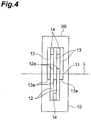
- Spacers 14 for keeping a predetermined distance are interposed between the adjacent first plate-shaped members 12 and between the adjacent second plate-shaped members 13.
- the tip end portion 12a of the first plate-shaped member 12 is provided with a first notch 16 opening to the predetermined line L.
- the tip end portion 13a of the second plate-shaped member 13 is provided with a second notch 17 opening to the predetermined line L.
- the region where the first notch 16 and the second notch 17 overlap each other on the predetermined line L serves as the through hole 11 that allows the CNT fibers F to pass through in contact with the through hole 11. That is, the first notch 16 and the second notch 17 define the through hole 11.
- the adjusting mechanism 10 adjusts the opening area of the through hole 11 by advancing and retreating the tip end portion 12a of each first plate-shaped member 12 and the tip end portion 13a of each second plate-shaped member 13 to/from the predetermined line L and adjusting the overlapping state of the first notch 16 and the second notch 17 on the predetermined line L.
- the adjusting mechanism 10 adjusts the aggregation state of the CNT fibers F.
- the CNT fibers F can be aggregated more densely as the opening area of the through hole 11 decreases.
- the resistive force exerting on the running CNT fibers F increases, so that the tension in the CNT fibers F can be increased on the downstream side from the preliminary aggregating unit 3B.
- the yarn producing apparatus 1 B can produce CNT yarn Y having sufficient strength as in the yarn producing apparatus 1A described above.
- the preliminary aggregating unit 3B includes the adjusting mechanism 10 for adjusting the aggregation state of the CNT fibers F.
- the CNT fibers F can be aggregated in desired density (for example, a density for aggregating to such a strength that can withstand the tension exerted on the downstream side from the preliminary aggregating unit 3B).
- the adjusting mechanism 10 can advance and retreat the tip end portion 12a of each first plate-shaped member 12 and the tip end portion 13a of each second plate-shaped member 13 to/from the predetermined line L, based on the amount of the CNT fibers F detected by a separate sensor, such that the opening area of the through hole 11 increases as the amount of the CNT fibers F increases.
- the preliminary aggregating unit 3B may be configured to include a biasing member such as a spring such that the tip end portion 12a of each first plate-shaped member 12 and the tip end portion 13a of each second plate-shaped member 13 move away from the predetermined line L when force is exerted in the direction vertical to the direction of the CNT fibers F running. This configuration can prevent the damage of the CNT fibers F even when the amount of the CNT fibers F abruptly increases.
- the adjusting mechanism 10 adjusts the aggregation state of the CNT fibers F by adjusting the positional relation between the first plate-shaped member 12 and the second plate-shaped member 13 and adjusting the opening area of the through hole 11.
- the magnitude of resistive force exerting on the CNT fibers F and the aggregation state of the CNT fibers F can be adjusted as desired. For example, even when the CNT fibers F clog the through hole 11, the CNT fibers F can be easily removed by increasing the distance between the first plate-shaped members 12 and the second plate-shaped members 13.
- the adjusting mechanism 10 may monitor the value of tension exerted on the CNT fibers F and then change the opening area of the through hole 11 by feedback control, depending on the result of the monitoring.
- an actuator is provided for actuating the adjusting mechanism 10. With this configuration, the value of tension exerted on the CNT fibers F can be maintained at a desired value.
- the adjusting mechanism 10 adjusts the opening area of the through hole 11 by moving the first plate-shaped member 12 and the second plate-shaped member 13 and thereby adjusting the overlapping state of the first notch 16 and the second notch 17. With this configuration, the opening area of the through hole 11 can be adjusted easily and reliably.
- the adjusting mechanism 10 may adjust the overlapping state of the first notch 16 and the second notch 17 by moving the first plate-shaped member 12 or the second plate-shaped member 13.
- the first plate-shaped members 12 and the second plate-shaped members 13 may be attached to a holding piece 18 and a holding piece 19, respectively.
- the holding piece 18 and the holding piece 19 swing about a line parallel to the predetermined line L.
- the holding piece 18 and the holding piece 19 are swung in directions different from each other, so that the tip end portion 12a of each first plate-shaped member 12 and the tip end portion 13a of each second plate-shaped member 13 can be advanced and retreated to/from the predetermined line L.
- the preliminary aggregating unit 3B may include a plurality of wires 51 and a plurality of holding pieces 52 as assembly parts configured to form the through hole 11 that allows the CNT fibers F to pass through in contact with the through hole 11.
- the wires 51 define the through hole 11.
- the holding pieces 52 hold the respective ends of the wires 51.
- the adjusting mechanism 10 may adjust the opening area of the through hole 11 by swinging the holding pieces 52 and thereby adjusting the overlapping state of the wires 51. Also in this case, the opening area of the through hole 11 can be adjusted easily and reliably.
- the centers about which the holding pieces 52 are swung are arranged at regular pitches on the same circle the center of which is on the predetermined line L.
- the supply source of the CNT fibers F may not be a CNT forming substrate S but may be a device that continuously synthesizes carbon nanotubes to supply the CNT fibers F.
- the twisting and winding device 5 may be replaced by, for example, a device that gives false twist to CNT fibers F and a device that winds the false-twisted CNT yarn around the winding tube.
- the present invention can provide a yarn producing apparatus capable of producing carbon nanotube yarn with sufficient strength.
- 1A, 1B ... yarn producing apparatus 2 ... substrate support, 3A, 3B ... preliminary aggregating unit, 4 ... tensioning unit, 5 ... twisting and winding device (twisting unit), 6 ... thin tube, 6a ... through hole, 10 ... adjusting mechanism, 11 ... through hole, 12 ... first plate-shaped member (assembly part), 13 ... second plate-shaped member (assembly part), 16 ... first notch, 17 ... second notch, 20 ... wind driving mechanism, 21 ... winding shaft, 30 ... twist driving mechanism, 31 ... guide, 40 ... traverse driving mechanism, 51 ... wire, 52 ... holding piece.
Landscapes
- Engineering & Computer Science (AREA)
- Textile Engineering (AREA)
- Mechanical Engineering (AREA)
- Yarns And Mechanical Finishing Of Yarns Or Ropes (AREA)
- Carbon And Carbon Compounds (AREA)
- Chemical & Material Sciences (AREA)
- Chemical Kinetics & Catalysis (AREA)
- General Chemical & Material Sciences (AREA)
Abstract
Description
- The present invention relates to a yarn producing apparatus for producing carbon nanotube yarn from carbon nanotube fibers while allowing the carbon nanotube fibers to run.
- A known example of the yarn producing apparatus as described above includes holding means for aggregating carbon nanotube fibers pulled out from a carbon nanotube forming substrate and twisting means for twisting the carbon nanotube fibers aggregated by the holding means (see, for example, Patent Literature 1).
- Patent Literature 2 (
FIG 4 ) discloses spinnerets or nozzles for creating alignment of the suspended nanotube arrays. The spinnerets or nozzles allow a significant increase in the intensity of the extensional flow in the nanotube suspension with an accompanying increase in the degree of carbon nanotube alignment. -
- [Patent Literature 1] Japanese Patent Application Laid-Open Publication No.
2010-116632 - [Patent Literature 2] Japanese Patent No.
3954967 - In the yarn producing apparatus described in
Patent Literature 1, since a pair of rotatable roller is used as the holding means for aggregating carbon nanotube fibers, resistive force does not stably exert on the carbon nanotube fibers against the running. As a result, twisting state by the twisting means may become unstable and the produced carbon nanotube yarn may not have sufficient strength. In order to produce carbon nanotube yarn having sufficient strength with the spinnerets or nozzles described inPatent Literature 2, the spinnerets or nozzles have to be replaced each time depending on a desired thickness of carbon nanotube yarn. - An object of the present invention, therefore, is to provide a yarn producing apparatus capable of producing carbon nanotube yarn with sufficient strength.
- A yarn producing apparatus according to the present invention produces carbon nanotube yarn from carbon nanotube fibers while allowing the carbon nanotube fibers to run. The yarn producing apparatus includes a preliminary aggregating unit configured to aggregate the carbon nanotube fibers while exerting resistive force on the carbon nanotube fibers against the running, and a twisting unit configured to twist the carbon nanotube fibers aggregated by the preliminary aggregating unit.
- In this yarn producing apparatus, when the preliminary aggregating unit aggregates the carbon nanotube fibers, resistive force is exerted on the carbon nanotube fibers against the running. The twisting unit, therefore, twists the carbon nanotube fibers in a state in which the carbon nanotube fibers are densely aggregated. This yarn producing apparatus thus can produce carbon nanotube yarn with sufficient strength.
- In the yarn producing apparatus according to the present invention, the preliminary aggregating unit may include an adjusting mechanism configured to adjust an aggregation state of the carbon nanotube fibers. With this configuration, for example, even when the amount of carbon nanotube fibers varies, the carbon nanotube fibers can be aggregated in desired density.
- In the yarn producing apparatus according to the present invention, the preliminary aggregating unit may further include a plurality of assembly parts configured to form a through hole allowing the carbon nanotube fibers to pass through in contact with the through hole. The adjusting mechanism may adjust the aggregation state of the carbon nanotube fibers by adjusting a positional relation between the assembly parts and adjusting an opening area of the through hole. With this configuration, the magnitude of resistive force exerted on the carbon nanotube fibers and the aggregation state of the carbon nanotube fibers can be adjusted as desired. For example, even when the carbon nanotube fibers clog the through hole, the carbon nanotube fibers can be easily removed by dissembling the assembly parts.
- In the yarn producing apparatus according to the present invention, the preliminary aggregating unit may further include a first plate-shaped member and a second plate-shaped member as the assembly parts. The first plate-shaped member and the second plate-shaped member may be provided with a first notch and a second notch respectively, the first notch and the second notch defining the through hole. The adjusting mechanism may adjust the opening area of the through hole by moving at least one of the first plate-shaped member and the second plate-shaped member and adjusting an overlapping state of the first notch and the second notch. With this configuration, the opening area of the through hole can be adjusted easily and reliably.
- In the yarn producing apparatus according to the present invention, the preliminary aggregating unit may further include a plurality of wires and a plurality of holding pieces as the assembly parts, the wires being configured to define the through hole, the holding pieces being configured to hold respective ends of the wires. The adjusting mechanism may adjust the opening area of the through hole by swinging each of the holding pieces and adjusting an overlapping state of the wires. With this configuration, the opening area of the through hole can be adjusted easily and reliably.
- In the yarn producing apparatus according to the present invention, the adjusting mechanism may monitor a value of tension exerting on the carbon nanotube fibers running between the preliminary aggregating unit and the twisting unit and may change the opening area of the through hole by feedback control, depending on a result of the monitoring. With this configuration, the value of tension exerting on the carbon nanotube fibers can be maintained at a desired value.
- The yarn producing apparatus according to the present invention may further include a tensioning unit configured to act on the carbon nanotube fibers running between the preliminary aggregating unit and the twisting unit and to apply tension to the carbon nanotube fibers to be twisted by the twisting unit. With this configuration, tension at a desired value can be applied to the carbon nanotube fibers, and the carbon nanotube fibers can be twisted in the twisting unit in a state in which the carbon nanotube fibers are densely aggregated.
- In the yarn producing apparatus according to the present invention, the tensioning unit may be a pneumatic tensioning mechanism configured to blow air to the carbon nanotube fibers to thereby exert force on the carbon nanotube fibers in a direction opposite to a direction of the carbon nanotube fibers running. With this configuration, tension can be appropriately applied to the carbon nanotube fibers without aggregating the carbon nanotube fibers more than necessary due to contact.
- In the yarn producing apparatus according to the present invention, the tensioning unit may be a gate-type tensioning mechanism configured to bend the carbon nanotube fibers by using comb tooth-shaped contact portions arranged alternately to thereby exert resistive force on the running carbon nanotube fibers. With this configuration, tension can be appropriately applied to the carbon nanotube fibers without aggregating the carbon nanotube fibers more than necessary.
- The yarn producing apparatus according to the present invention may further include a substrate support configured to support a carbon nanotube forming substrate, the carbon nanotube fibers being drawn from the carbon nanotube forming substrate. With this configuration, the carbon nanotube fibers can be stably supplied.
- In the yarn producing apparatus according to the present invention, the twisting unit may include a wind driving mechanism configured to allow a winding shaft provided with a winding tube to rotate about the winding centerline of the winding shaft to thereby wind the carbon nanotube yarn onto the winding tube, a twist driving mechanism configured to allow a guide to rotate around the winding tube, the guide being configured to guide the carbon nanotube yarn to the winding tube, to thereby twist the carbon nanotube fibers and produce the carbon nanotube yarn while allowing the carbon nanotube fibers, carbon nanotube yarn, or both to swirl, and a traverse driving mechanism configured to allow the guide to reciprocate relative to the winding tube along the winding centerline of the winding shaft to thereby allow the carbon nanotube yarn to traverse the winding tube. With this configuration, the carbon nanotube fibers, carbon nanotube yarn, or both are twisted and a balloon (the carbon nanotube fibers, carbon nanotube yarn, or both expanding like a balloon under centrifugal force) is formed, whereby the balloon can appropriately absorb tension variations produced in the relatively less elastic carbon nanotube fibers, and the carbon nanotube fibers can be twisted efficiently.
- The present invention can provide a yarn producing apparatus capable of producing carbon nanotube yarn with sufficient strength.
-
-
FIG 1 is a plan view of a yarn producing apparatus according to a first embodiment of the present invention. -
FIG. 2 is a partial cross-sectional view of a twisting and winding device in the yarn producing apparatus inFIG. 1 . -
FIG. 3 is a plan view of a yarn producing apparatus according to a second embodiment of the present invention. -
FIG 4 is a plan view of a preliminary aggregating unit in the yarn producing apparatus inFIG 3 . -
FIG. 5 is a front view of first and second plate-shaped members in the preliminary aggregating unit inFIG 4 . -
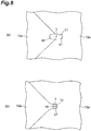
FIG. 6 is an enlarged view of the main parts of the first and second plate-shaped members inFIG 5 . -
FIG 7 is a perspective view of a modification to the preliminary aggregating unit in the yarn producing apparatus inFIG. 3 . -
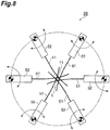
FIG 8 is a front view of a modification to the preliminary aggregating unit in the yarn producing apparatus inFIG 3 . - Preferred embodiments of the present invention will be described in details below with reference to the figures. It should be noted that the same or corresponding parts in the figures are denoted with the same reference signs and an overlapping description will be omitted.
- As shown in
FIG 1 , ayarn producing apparatus 1A is an apparatus that produces carbon nanotube yarn (hereinafter referred to as "CNT yarn") Y from carbon nanotube fibers (hereinafter referred to as "CNT fibers") F while allowing the CNT fibers F to run. Theyarn producing apparatus 1A includes asubstrate support 2, a preliminary aggregatingunit 3A, atensioning unit 4, and a twisting and winding device (twisting unit) 5. The substrate support 2, the preliminary aggregatingunit 3A, thetensioning unit 4, and the twisting andwinding device 5 are arranged in this order on a predetermined straight line L. The CNT fibers F run from thesubstrate support 2 toward the twisting and windingdevice 5. The CNT fibers F are a set of a plurality of fiber threads (fibers) of carbon nanotube. The CNT yarn Y is the twisted (genuine-twisted or false-twisted) CNT fibers F. - The
substrate support 2 supports a carbon nanotube forming substrate (hereinafter referred to as "CNT forming substrate") S from which the CNT fibers F are drawn, in a state of holding the CNT forming substrate S. The CNT forming substrate S is called a carbon nanotube forest or a vertically aligned carbon nanotube structure in which high-density and highly-oriented carbon nanotubes (for example, single-wall carbon nanotubes, double-wall carbon nanotubes, or multi-wall carbon nanotubes) are formed on a substrate by chemical vapor deposition or any other process. Examples of the substrate include a glass substrate, a silicon substrate, and a metal substrate. For example, at the start of production of the CNT yarn Y or during replacement of the CNT forming substrates S, a tool called microdrill can be used to draw the CNT fibers F from the CNT forming substrate S. In place of a microdrill, a suction device, an adhesive tape, or any other means may be used to draw the CNT fibers F from the CNT forming substrate S. - The preliminary aggregating
unit 3A aggregates the CNT fibers F while exerting resistive force on the CNT fibers F against the running when the CNT fibers F drawn from the CNT forming substrate S run toward the twisting and windingdevice 5. More specifically, the preliminary aggregatingunit 3A aggregates the CNT fibers F to such an extent that the CNT fibers F can be twisted in the subsequent stage. The preliminary aggregatingunit 3A includes athin tube 6. Thethin tube 6 is integrally formed of, for example, ruby. - The
thin tube 6 is shaped like a circular tube tapered to the downstream side in the direction of the CNT fibers F running (hereinafter simply referred to as "downstream side") in the downstream end portion. The tapered end of thethin tube 6 has a throughhole 6a that allows the CNT fibers F to pass through in contact with the throughhole 6a. - The
tensioning unit 4 acts on the CNT fibers F running between the preliminary aggregatingunit 3A and the twisting and windingdevice 5 and to apply tension to the CNT fibers F to be twisted by the twisting and windingdevice 5. More specifically, thetensioning unit 4 is a pneumatic tensioning mechanism configured to blow air to the CNT fibers F toward the upstream side in the direction of the CNT fibers F running (hereinafter simply referred to as "upstream side") to thereby exert force on the CNT fibers F in the direction opposite to the direction of the CNT fibers F running. Thetensioning unit 4 may be a gate-type tensioning mechanism configured to bend the CNT fibers F by using comb tooth-shaped contact portions arranged alternately to thereby exert resistive force on the running CNT fibers F. Alternatively, thetensioning unit 4 may be a disk-type tensioning mechanism or any other tensioning mechanism. - The twisting and winding
device 5 winds the produced CNT yarn Y onto a winding tube while twisting the CNT fibers F aggregated by the preliminary aggregatingunit 3A. More specifically, as shown inFIG 2 , the twisting and windingdevice 5 includes awind driving mechanism 20 for winding the CNT yarn Y onto a winding tube T, atwist driving mechanism 30 for twisting the CNT fibers F and producing the CNT yarn Y while forming a balloon B of the CNT fibers F, CNT yarn Y, or both, and atraverse driving mechanism 40 for allowing the CNT yarn Y to traverse the winding tube T. - The
wind driving mechanism 20 includes a windingshaft 21 having the winding centerline on the predetermined line L and awind driving motor 22 for rotating the windingshaft 21. The winding tube T is attached to atip end portion 21a that is the upstream end of the windingshaft 21, and is removable from the windingshaft 21. Abase end portion 21b that is the downstream end of the windingshaft 21 is coupled to thedrive shaft 22a of thewind driving motor 22 with ashaft coupling 23. The windingshaft 21 is supported on aframe 5a of the twisting and windingdevice 5 with abearing 24. Thewind driving motor 22 is fixed to theframe 5a. Thewind driving mechanism 20 as described above winds the CNT yarn Y onto the winding tube T by driving thewind driving motor 22 so that the windingshaft 21 provided with the winding tube T is rotated about the winding centerline (that is, the predetermined line L). - The
twist driving mechanism 30 includes aguide 31 for guiding the CNT yarn Y to the winding tube T and atwist driving motor 32 for rotating theguide 31 around the winding tube T. Theguide 31 includes atubular body 31a surrounding the windingshaft 21 and a pair ofarms 31 b extending on the upstream side from thebody 31 a. A tip end portion that is the upstream end of onearm 31b has aninsertion hole 31c through which the CNT yarn Y is inserted to be guided to the winding tube T. The CNT yarn Y to be inserted through theinsertion hole 31c is passed through aguide ring 35 arranged on the predetermined line L in a state of the CNT fibers F, CNT yarn Y, or both, and guided to the winding tube T. Thebody 31a of theguide 31 is coupled to thedrive shaft 32a of thetwist driving motor 32 with a plurality of spur gears 33. Theguide 31, thetwist driving motor 32, and thespur gear 33 are supported by astage 34 attached to theframe 5a so as to be able to reciprocate along the predetermined line L. For example, a bush serving as a slide bearing may be disposed between the windingshaft 21 and thebody 31a. Thetwist driving mechanism 30 as described above twists the CNT fibers F and produces the CNT yarn Y while allowing the CNT fibers F, CNT yarn Y, or both to swirl on theguide ring 35 serving as a fulcrum, by driving thetwist driving motor 32 so that theguide 31 for guiding the CNT yarn Y to the winding tube T is rotated around the winding tube T. The term "the CNT fibers F, CNT yarn Y, or both" inclusively means the CNT fibers F in a raw state, the CNT fibers F twisted into CNT yarn Y, and the intermediate therebetween. - The
traverse driving mechanism 40 includes aball screw shaft 41 having the centerline parallel to the predetermined line L, aball screw nut 42 screwed onto theball screw shaft 41, and atraverse driving motor 43 for rotating theball screw shaft 41. A base end portion that is the downstream end of theball screw shaft 41 is coupled to thedrive shaft 43a of thetraverse driving motor 43 with ashaft coupling 44. The ball screwnut 42 is fixed to thestage 34 of thetwist driving mechanism 30. Thetraverse driving motor 43 is fixed to theframe 5a. Thetraverse driving mechanism 40 as described above allows the CNT yarn Y to traverse the winding tube T by driving thetraverse driving motor 43 so that theball screw shaft 41 is rotated in the positive direction and the negative direction and thetwist driving mechanism 30 reciprocates along the predetermined line L (that is, theguide 31 reciprocates relative to the winding tube T along the winding centerline of the winding shaft 21). In order to allow the CNT yarn Y to traverse the winding tube T, for example, the winding tube T may be allowed to reciprocate relative to theguide 31 along the winding centerline of the windingshaft 21 as long as theguide 31 can reciprocate relative to the winding tube T along the winding centerline of the windingshaft 21. - As described above, in the
yarn producing apparatus 1A, when the preliminary aggregatingunit 3A aggregates the CNT fibers F, resistive force is exerted on the CNT fibers F against the running. The twisting and windingdevice 5 therefore twists the CNT fibers F in a state in which the CNT fibers F are densely aggregated. Theyarn producing apparatus 1A thus can produce CNT yarn Y having sufficient strength. - In the
yarn producing apparatus 1A, the preliminary aggregatingunit 3A includes thethin tube 6 provided with the throughhole 6a that allows the CNT fibers F to pass through in contact with the throughhole 6a. With this configuration, exertion of resistive force on the CNT fibers F and aggregation of the CNT fibers F are accomplished with a simple structure. - The
yarn producing apparatus 1A includes thetensioning unit 4 for applying tension to the CNT fibers F running between the preliminary aggregatingunit 3A and the twisting and windingdevice 5. With this configuration, tension at a desired value can be applied to the CNT fibers F, and the CNT fibers F can be twisted in the twisting and windingdevice 5 in a state in which the CNT fibers F are densely aggregated. - In the
yarn producing apparatus 1A, a pneumatic tensioning mechanism is used as thetensioning unit 4. With this configuration, tension can be appropriately applied to the CNT fibers F without aggregating the CNT fibers F more than necessary due to contact. - The
yarn producing apparatus 1A includes thesubstrate support 2 for supporting the CNT forming substrate S from which CNT fibers F are drawn. With this configuration, the CNT fibers F can be stably supplied. - In the twisting and winding
device 5 in theyarn producing apparatus 1A, theguide 31 for guiding the CNT yarn Y to the winding tube T is rotated around the winding tube T, whereby the CNT fibers F are twisted and CNT yarn Y is produced while allowing the CNT fibers F, CNT yarn Y, or both to swirl. With this configuration, the CNT fibers F, CNT yarn Y, or both swirl and a balloon B is formed. While the balloon B can appropriately absorb tension variations produced in relatively less elastic CNT fibers F, the CNT fibers F can be twisted efficiently. In the foregoing embodiment, CNT yarn Y is produced by twisting the CNT fibers F while forming a balloon B. Alternatively, the CNT yarn Y may be produced by twisting the CNT fibers F in a condition under which no balloon B is formed. - As shown in
FIG. 3 , ayarn producing apparatus 1B mainly differs from theyarn producing apparatus 1A described above in that a preliminary aggregatingunit 3B includes anadjusting mechanism 10. The preliminary aggregatingunit 3B includes a plurality of first plate-shapedmembers 12 and a plurality of second plate-shapedmembers 13 as assembly parts configured to form a throughhole 11 that allows the CNT fibers F to pass through in contact with the throughhole 11. Theadjusting mechanism 10 adjusts the aggregation state of the CNT fibers F by adjusting the positional relation between the first plate-shapedmembers 12 and the second plate-shapedmembers 13 and adjusting the opening area of the throughhole 11. - A plurality of (for example, two) first plate-shaped
members 12 are attached at a predetermined distance from each other to theadjusting mechanism 10 on one side of the predetermined line L. A plurality of (for example, three) second plate-shapedmembers 13 are attached at a distance from each other to theadjusting mechanism 10 on the other side of the predetermined line L. As shown inFIG 4 , the adjustingmechanism 10 advances and retreats thetip end portion 12a of each first plate-shapedmember 12 and thetip end portion 13a of each second plate-shapedmember 13 to/from the predetermined line L, so that thetip end portions 12a and thetip end portions 13 a are arranged alternately on the predeterminedline L. Spacers 14 for keeping a predetermined distance are interposed between the adjacent first plate-shapedmembers 12 and between the adjacent second plate-shapedmembers 13. - As shown in
FIG 5 , thetip end portion 12a of the first plate-shapedmember 12 is provided with afirst notch 16 opening to the predetermined line L. Thetip end portion 13a of the second plate-shapedmember 13 is provided with asecond notch 17 opening to the predetermined line L. As shown inFIG 6 , the region where thefirst notch 16 and thesecond notch 17 overlap each other on the predetermined line L (for example, an oval region as shown inFIG 6(a) or a circular region as shown inFIG 6(b) ) serves as the throughhole 11 that allows the CNT fibers F to pass through in contact with the throughhole 11. That is, thefirst notch 16 and thesecond notch 17 define the throughhole 11. - The
adjusting mechanism 10 adjusts the opening area of the throughhole 11 by advancing and retreating thetip end portion 12a of each first plate-shapedmember 12 and thetip end portion 13a of each second plate-shapedmember 13 to/from the predetermined line L and adjusting the overlapping state of thefirst notch 16 and thesecond notch 17 on the predetermined line L. With this configuration, the adjustingmechanism 10 adjusts the aggregation state of the CNT fibers F. For example, the CNT fibers F can be aggregated more densely as the opening area of the throughhole 11 decreases. As the opening area of the throughhole 11 decreases, the resistive force exerting on the running CNT fibers F increases, so that the tension in the CNT fibers F can be increased on the downstream side from the preliminary aggregatingunit 3B. - As described above, the
yarn producing apparatus 1 B can produce CNT yarn Y having sufficient strength as in theyarn producing apparatus 1A described above. - In the
yarn producing apparatus 1B, the preliminary aggregatingunit 3B includes theadjusting mechanism 10 for adjusting the aggregation state of the CNT fibers F. With this configuration, for example, even when the amount of the CNT fibers F drawn from the CNT forming substrate S varies, the CNT fibers F can be aggregated in desired density (for example, a density for aggregating to such a strength that can withstand the tension exerted on the downstream side from the preliminary aggregatingunit 3B). - More specifically, the adjusting
mechanism 10 can advance and retreat thetip end portion 12a of each first plate-shapedmember 12 and thetip end portion 13a of each second plate-shapedmember 13 to/from the predetermined line L, based on the amount of the CNT fibers F detected by a separate sensor, such that the opening area of the throughhole 11 increases as the amount of the CNT fibers F increases. The preliminary aggregatingunit 3B may be configured to include a biasing member such as a spring such that thetip end portion 12a of each first plate-shapedmember 12 and thetip end portion 13a of each second plate-shapedmember 13 move away from the predetermined line L when force is exerted in the direction vertical to the direction of the CNT fibers F running. This configuration can prevent the damage of the CNT fibers F even when the amount of the CNT fibers F abruptly increases. - In the
yarn producing apparatus 1B, the adjustingmechanism 10 adjusts the aggregation state of the CNT fibers F by adjusting the positional relation between the first plate-shapedmember 12 and the second plate-shapedmember 13 and adjusting the opening area of the throughhole 11. With this configuration, the magnitude of resistive force exerting on the CNT fibers F and the aggregation state of the CNT fibers F can be adjusted as desired. For example, even when the CNT fibers F clog the throughhole 11, the CNT fibers F can be easily removed by increasing the distance between the first plate-shapedmembers 12 and the second plate-shapedmembers 13. Theadjusting mechanism 10 may monitor the value of tension exerted on the CNT fibers F and then change the opening area of the throughhole 11 by feedback control, depending on the result of the monitoring. In this case, an actuator is provided for actuating theadjusting mechanism 10. With this configuration, the value of tension exerted on the CNT fibers F can be maintained at a desired value. - In the
yarn producing apparatus 1B, the adjustingmechanism 10 adjusts the opening area of the throughhole 11 by moving the first plate-shapedmember 12 and the second plate-shapedmember 13 and thereby adjusting the overlapping state of thefirst notch 16 and thesecond notch 17. With this configuration, the opening area of the throughhole 11 can be adjusted easily and reliably. Theadjusting mechanism 10 may adjust the overlapping state of thefirst notch 16 and thesecond notch 17 by moving the first plate-shapedmember 12 or the second plate-shapedmember 13. - As shown in
FIG 7 , the first plate-shapedmembers 12 and the second plate-shapedmembers 13 may be attached to a holdingpiece 18 and a holdingpiece 19, respectively. The holdingpiece 18 and the holdingpiece 19 swing about a line parallel to the predetermined line L. In this case, the holdingpiece 18 and the holdingpiece 19 are swung in directions different from each other, so that thetip end portion 12a of each first plate-shapedmember 12 and thetip end portion 13a of each second plate-shapedmember 13 can be advanced and retreated to/from the predetermined line L. - As shown in
FIG 8 , the preliminary aggregatingunit 3B may include a plurality ofwires 51 and a plurality of holdingpieces 52 as assembly parts configured to form the throughhole 11 that allows the CNT fibers F to pass through in contact with the throughhole 11. Thewires 51 define the throughhole 11. The holdingpieces 52 hold the respective ends of thewires 51. Theadjusting mechanism 10 may adjust the opening area of the throughhole 11 by swinging the holdingpieces 52 and thereby adjusting the overlapping state of thewires 51. Also in this case, the opening area of the throughhole 11 can be adjusted easily and reliably. The centers about which the holdingpieces 52 are swung are arranged at regular pitches on the same circle the center of which is on the predetermined line L. - Although the first and the second embodiments of the present invention have been described above, the present invention is not intended to be limited to the foregoing embodiments. For example, the supply source of the CNT fibers F may not be a CNT forming substrate S but may be a device that continuously synthesizes carbon nanotubes to supply the CNT fibers F. The twisting and winding
device 5 may be replaced by, for example, a device that gives false twist to CNT fibers F and a device that winds the false-twisted CNT yarn around the winding tube. - The present invention can provide a yarn producing apparatus capable of producing carbon nanotube yarn with sufficient strength.
- 1A, 1B ... yarn producing apparatus, 2 ... substrate support, 3A, 3B ... preliminary aggregating unit, 4 ... tensioning unit, 5 ... twisting and winding device (twisting unit), 6 ... thin tube, 6a ... through hole, 10 ... adjusting mechanism, 11 ... through hole, 12 ... first plate-shaped member (assembly part), 13 ... second plate-shaped member (assembly part), 16 ... first notch, 17 ... second notch, 20 ... wind driving mechanism, 21 ... winding shaft, 30 ... twist driving mechanism, 31 ... guide, 40 ... traverse driving mechanism, 51 ... wire, 52 ... holding piece.
Claims (11)
- A yarn producing apparatus for producing carbon nanotube yarn from carbon nanotube fibers while allowing the carbon nanotube fibers to run, the yarn producing apparatus comprising:a preliminary aggregating unit configured to aggregate the carbon nanotube fibers while exerting resistive force on the carbon nanotube fibers against the running; anda twisting unit configured to twist the carbon nanotube fibers aggregated by the preliminary aggregating unit.
- The yarn producing apparatus according to claim 1, wherein
the preliminary aggregating unit includes an adjusting mechanism configured to adjust an aggregation state of the carbon nanotube fibers. - The yarn producing apparatus according to claim 2, wherein
the preliminary aggregating unit further includes a plurality of assembly parts configured to form the through hole allowing the carbon nanotube fibers to pass through in contact with the through hole, and
the adjusting mechanism adjusts the aggregation state of the carbon nanotube fibers by adjusting a positional relation between the assembly parts and adjusting an opening area of the through hole. - The yarn producing apparatus according to claim 3, wherein
the preliminary aggregating unit further includes a first plate-shaped member and a second plate-shaped member as the assembly parts, the first plate-shaped member and the second plate-shaped member being provided with a first notch and a second notch respectively, the first notch and the second notch defining the through hole, and
the adjusting mechanism adjusts the opening area of the through hole by moving at least one of the first plate-shaped member and the second plate-shaped member and adjusting an overlapping state of the first notch and the second notch. - The yarn producing apparatus according to claim 3, wherein
the preliminary aggregating unit further includes a plurality of wires and a plurality of holding pieces as the assembly parts, the wires being configured to define the through hole, the holding pieces being configured to hold respective ends of the wires, and
the adjusting mechanism adjusts the opening area of the through hole by swinging each of the holding pieces and adjusting an overlapping state of the wires. - The yarn producing apparatus according to any one of claims 3 to 5, wherein the adjusting mechanism monitors a value of tension exerting on the carbon nanotube fibers running between the preliminary aggregating unit and the twisting unit and changes the opening area of the through hole by feedback control, depending on a result of the monitoring.
- The yarn producing apparatus according to any one of claims 1 to 6, further comprising a tensioning unit configured to act on the carbon nanotube fibers running between the preliminary aggregating unit and the twisting unit and to apply tension to the carbon nanotube fibers to be twisted by the twisting unit.
- The yarn producing apparatus according to claim 7, wherein
the tensioning unit is a pneumatic tensioning mechanism configured to blow air to the carbon nanotube fibers to thereby exert force on the carbon nanotube fibers in a direction opposite to a direction of the carbon nanotube fibers running. - The yarn producing apparatus according to claim 7, wherein
the tensioning unit is a gate-type tensioning mechanism configured to bend the carbon nanotube fibers by using comb tooth-shaped contact portions arranged alternately to thereby exert resistive force on the running carbon nanotube fibers. - The yarn producing apparatus according to any one of claims 1 to 9, further comprising a substrate support configured to support a carbon nanotube forming substrate, the carbon nanotube fibers being drawn from the carbon nanotube forming substrate.
- The yarn producing apparatus according to any one of claims 1 to 10, wherein
the twisting unit includes:a wind driving mechanism configured to allow a winding shaft provided with a winding tube to rotate about the winding centerline of the winding shaft to thereby wind the carbon nanotube yarn onto the winding tube;a twist driving mechanism configured to allow a guide to rotate around the winding tube, the guide being configured to guide the carbon nanotube yarn to the winding tube, to thereby twist the carbon nanotube fibers and produce the carbon nanotube yarn while allowing the carbon nanotube fibers, carbon nanotube yarn, or both to swirl; anda traverse driving mechanism configured to allow the guide to reciprocate relative to the winding tube along the winding centerline of the winding shaft to thereby allow the carbon nanotube yarn to traverse the winding tube.
Priority Applications (1)
| Application Number | Priority Date | Filing Date | Title |
|---|---|---|---|
| EP17205110.4A EP3312320B1 (en) | 2013-07-22 | 2013-07-22 | Carbon nanotube yarn production device |
Applications Claiming Priority (3)
| Application Number | Priority Date | Filing Date | Title |
|---|---|---|---|
| EP13890206.9A EP3026159A4 (en) | 2013-07-22 | 2013-07-22 | Thread production device |
| EP17205110.4A EP3312320B1 (en) | 2013-07-22 | 2013-07-22 | Carbon nanotube yarn production device |
| PCT/JP2013/069798 WO2015011761A1 (en) | 2013-07-22 | 2013-07-22 | Thread production device |
Related Parent Applications (1)
| Application Number | Title | Priority Date | Filing Date |
|---|---|---|---|
| EP13890206.9A Division EP3026159A4 (en) | 2013-07-22 | 2013-07-22 | Thread production device |
Publications (2)
| Publication Number | Publication Date |
|---|---|
| EP3312320A1 true EP3312320A1 (en) | 2018-04-25 |
| EP3312320B1 EP3312320B1 (en) | 2022-03-16 |
Family
ID=52392846
Family Applications (2)
| Application Number | Title | Priority Date | Filing Date |
|---|---|---|---|
| EP13890206.9A Withdrawn EP3026159A4 (en) | 2013-07-22 | 2013-07-22 | Thread production device |
| EP17205110.4A Not-in-force EP3312320B1 (en) | 2013-07-22 | 2013-07-22 | Carbon nanotube yarn production device |
Family Applications Before (1)
| Application Number | Title | Priority Date | Filing Date |
|---|---|---|---|
| EP13890206.9A Withdrawn EP3026159A4 (en) | 2013-07-22 | 2013-07-22 | Thread production device |
Country Status (7)
| Country | Link |
|---|---|
| US (1) | US10351977B2 (en) |
| EP (2) | EP3026159A4 (en) |
| JP (1) | JP5943149B2 (en) |
| KR (1) | KR20160003738A (en) |
| CN (1) | CN105408535B (en) |
| TW (1) | TW201516203A (en) |
| WO (1) | WO2015011761A1 (en) |
Families Citing this family (9)
| Publication number | Priority date | Publication date | Assignee | Title |
|---|---|---|---|---|
| KR101730948B1 (en) * | 2013-07-22 | 2017-04-27 | 무라다기카이가부시끼가이샤 | Thread production device, and aggregating part |
| JP6015861B2 (en) * | 2013-07-22 | 2016-10-26 | 村田機械株式会社 | Yarn manufacturing equipment |
| WO2015011755A1 (en) * | 2013-07-22 | 2015-01-29 | 村田機械株式会社 | Thread production device |
| WO2015011768A1 (en) * | 2013-07-22 | 2015-01-29 | 村田機械株式会社 | Yarn manufacturing device |
| US10472739B2 (en) * | 2013-07-22 | 2019-11-12 | Murata Machinery Ltd. | Yarn manufacturing device |
| WO2018118682A1 (en) * | 2016-12-19 | 2018-06-28 | Lintec Of America, Inc. | Nanofiber yarn spinning system |
| US11161743B2 (en) * | 2018-05-09 | 2021-11-02 | Lintec Of America, Inc. | Applying micron diameter yarns |
| JP7783102B2 (en) * | 2021-04-02 | 2025-12-09 | トヨタ自動車株式会社 | Method for manufacturing spun yarn made of carbon nanotubes and spun yarn made of carbon nanotubes |
| CN114803674A (en) * | 2022-05-09 | 2022-07-29 | 苏州卓米纺织科技有限公司 | Two-for-one twisting device for yarn processing and using method thereof |
Citations (5)
| Publication number | Priority date | Publication date | Assignee | Title |
|---|---|---|---|---|
| US4235070A (en) * | 1978-09-20 | 1980-11-25 | Dynamex Corporation | Wire stranding machine and control means therefor |
| JP3954967B2 (en) | 2000-11-03 | 2007-08-08 | ハネウェル・インターナショナル・インコーポレーテッド | Spinning, processing, and utilization of carbon nanotube filaments, ribbons, and yarns |
| JP2010116632A (en) | 2008-11-11 | 2010-05-27 | Osaka Prefecture | Apparatus and method for producing fine carbon fiber twisted yarn |
| JP2011153392A (en) * | 2010-01-28 | 2011-08-11 | Osaka Prefecture | Carbon nanotube twisted yarn, and method for producing the same |
| WO2012127814A1 (en) * | 2011-03-23 | 2012-09-27 | 株式会社神戸製鋼所 | Production method and production device for long fiber-reinforced resin strand |
Family Cites Families (24)
| Publication number | Priority date | Publication date | Assignee | Title |
|---|---|---|---|---|
| US2731786A (en) * | 1954-07-01 | 1956-01-24 | klein | |
| US3563018A (en) * | 1969-03-20 | 1971-02-16 | Anaconda Wire & Cable Co | Winding machine guide |
| JP2005097750A (en) | 2000-09-28 | 2005-04-14 | Toray Eng Co Ltd | Polyester fiber and method for producing polyester fiber |
| US6601880B2 (en) * | 2001-05-01 | 2003-08-05 | Wulftec International Inc. | Method and apparatus for making a knot with flexible material wrapped around an article |
| JP3833654B2 (en) * | 2001-06-12 | 2006-10-18 | 三菱レイヨン株式会社 | Carbon fiber manufacturing apparatus and manufacturing method thereof |
| US6991702B2 (en) * | 2001-07-04 | 2006-01-31 | Nag-Yong Kim | Electronic spinning apparatus |
| DE10201577A1 (en) * | 2002-01-17 | 2003-07-31 | Schlafhorst & Co W | Spinning device for producing a spun thread by means of a circulating air stream |
| WO2006018036A1 (en) * | 2004-08-10 | 2006-02-23 | Toho Tenax Europe Gmbh | Cabled carbon-fibre thread |
| CN108425170B (en) * | 2004-11-09 | 2021-02-26 | 得克萨斯大学体系董事会 | Manufacture and use of nanofiber yarns, tapes and sheets |
| CA2897320A1 (en) * | 2005-07-28 | 2007-01-28 | Nanocomp Technologies, Inc. | Systems and methods for formation and harvesting of nanofibrous materials |
| WO2008022129A2 (en) * | 2006-08-14 | 2008-02-21 | Cnt Technologies, Inc. | System and methods for spinning carbon nanotubes into yarn, and yarn made therefrom |
| EP2092095B1 (en) * | 2006-11-20 | 2017-03-08 | Stellenbosch University | A yarn and a process for manufacture thereof |
| US7709732B2 (en) * | 2006-12-12 | 2010-05-04 | Motorola, Inc. | Carbon nanotubes litz wire for low loss inductors and resonators |
| US8286413B2 (en) * | 2007-02-05 | 2012-10-16 | Commonwealth Scientific And Industrial Research Organisation | Nanofibre yarns |
| JP5509559B2 (en) | 2008-09-10 | 2014-06-04 | 東レ株式会社 | Method and apparatus for producing carbon nanotube continuous fiber |
| CN102001641B (en) * | 2009-08-28 | 2013-06-05 | 清华大学 | Method for preparing carbon nanotube linear structure |
| DE102011116936A1 (en) * | 2010-11-29 | 2012-05-31 | Amann & Söhne GmbH & Co. KG | Yarn, in particular sewing or embroidery thread and method for producing such a yarn |
| CN102953171A (en) * | 2011-08-30 | 2013-03-06 | 苏州捷迪纳米科技有限公司 | Carbon nanotube spinning machine and method for preparing carbon nanotube yarns by use of same |
| JP2014169521A (en) * | 2013-02-05 | 2014-09-18 | Honda Motor Co Ltd | Carbon nanotube fiber and manufacturing method thereof |
| EP3018242B1 (en) * | 2013-07-05 | 2019-10-23 | Murata Machinery, Ltd. | Yarn manufacturing apparatus |
| KR101730948B1 (en) * | 2013-07-22 | 2017-04-27 | 무라다기카이가부시끼가이샤 | Thread production device, and aggregating part |
| WO2015011755A1 (en) * | 2013-07-22 | 2015-01-29 | 村田機械株式会社 | Thread production device |
| WO2015011768A1 (en) * | 2013-07-22 | 2015-01-29 | 村田機械株式会社 | Yarn manufacturing device |
| US10472739B2 (en) * | 2013-07-22 | 2019-11-12 | Murata Machinery Ltd. | Yarn manufacturing device |
-
2013
- 2013-07-22 US US14/905,202 patent/US10351977B2/en active Active
- 2013-07-22 KR KR1020157033205A patent/KR20160003738A/en not_active Abandoned
- 2013-07-22 CN CN201380078263.8A patent/CN105408535B/en active Active
- 2013-07-22 EP EP13890206.9A patent/EP3026159A4/en not_active Withdrawn
- 2013-07-22 JP JP2015528030A patent/JP5943149B2/en not_active Expired - Fee Related
- 2013-07-22 EP EP17205110.4A patent/EP3312320B1/en not_active Not-in-force
- 2013-07-22 WO PCT/JP2013/069798 patent/WO2015011761A1/en not_active Ceased
-
2014
- 2014-07-17 TW TW103124552A patent/TW201516203A/en unknown
Patent Citations (5)
| Publication number | Priority date | Publication date | Assignee | Title |
|---|---|---|---|---|
| US4235070A (en) * | 1978-09-20 | 1980-11-25 | Dynamex Corporation | Wire stranding machine and control means therefor |
| JP3954967B2 (en) | 2000-11-03 | 2007-08-08 | ハネウェル・インターナショナル・インコーポレーテッド | Spinning, processing, and utilization of carbon nanotube filaments, ribbons, and yarns |
| JP2010116632A (en) | 2008-11-11 | 2010-05-27 | Osaka Prefecture | Apparatus and method for producing fine carbon fiber twisted yarn |
| JP2011153392A (en) * | 2010-01-28 | 2011-08-11 | Osaka Prefecture | Carbon nanotube twisted yarn, and method for producing the same |
| WO2012127814A1 (en) * | 2011-03-23 | 2012-09-27 | 株式会社神戸製鋼所 | Production method and production device for long fiber-reinforced resin strand |
Non-Patent Citations (3)
| Title |
|---|
| JAYASINGHE C., CHAKRABARTI S., SCHULZ M.J., SHANOV V.: "Spinning yarn from long carbon nanotube arrays", JOURNAL OF MATERIAL RESEARCH, vol. 26, no. 5, 28 January 2011 (2011-01-28), pages 645 - 651, XP002769143, DOI: /10.1557/jmr.2010.91 * |
| MIAO M., MCDONNELL J., VUCKOVIC L., HAWKINS S.C.: "Poisson's ratio and porosity of carbon nanotube dry-spun yarns", CARBON, vol. 48, no. 10, 10 April 2010 (2010-04-10), pages 2802 - 2811, XP002769142, DOI: /10.1016/j.carbon.2010.04.009 * |
| TRAN C.D., HUMPHRIES W., SMITH S.M., HUYNH C., LUCAS S.: "Improving the tensile strength of carbon nanotube spun yarns using a modified spinning process", CARBON, vol. 47, no. 11, 27 May 2009 (2009-05-27), pages 2662 - 2670, XP002769141, DOI: /10.1016/j.carbon.2009.05.020 * |
Also Published As
| Publication number | Publication date |
|---|---|
| EP3312320B1 (en) | 2022-03-16 |
| EP3026159A1 (en) | 2016-06-01 |
| US10351977B2 (en) | 2019-07-16 |
| KR20160003738A (en) | 2016-01-11 |
| JPWO2015011761A1 (en) | 2017-03-02 |
| CN105408535A (en) | 2016-03-16 |
| EP3026159A4 (en) | 2017-05-31 |
| TW201516203A (en) | 2015-05-01 |
| JP5943149B2 (en) | 2016-06-29 |
| CN105408535B (en) | 2017-10-13 |
| WO2015011761A1 (en) | 2015-01-29 |
| US20160160401A1 (en) | 2016-06-09 |
Similar Documents
| Publication | Publication Date | Title |
|---|---|---|
| EP3026153A1 (en) | Thread production device, and aggregating part | |
| EP3312320B1 (en) | Carbon nanotube yarn production device | |
| US10017882B2 (en) | Thread production device | |
| US9945053B2 (en) | Yarn manufacturing apparatus | |
| US10450678B2 (en) | Yarn manufacturing device | |
| EP3176294A1 (en) | Tensor, draft device, and spinning machine | |
| CN206591216U (en) | A kind of twister of two-for-one twister and the two-for-one twister using the twister | |
| WO2023021824A1 (en) | Yarn winder | |
| US10179959B2 (en) | Yarn manufacturing device | |
| CN202265654U (en) | Adjustable device for filament location and silk guide control for embedded spinning | |
| WO2015011767A1 (en) | Thread production device | |
| WO2015011770A1 (en) | Thread production device | |
| US20120167634A1 (en) | Apparatus for winding filaments or strands | |
| CN102505221A (en) | Rough yarn feeding method of segmented colored yarn production process |
Legal Events
| Date | Code | Title | Description |
|---|---|---|---|
| PUAI | Public reference made under article 153(3) epc to a published international application that has entered the european phase |
Free format text: ORIGINAL CODE: 0009012 |
|
| STAA | Information on the status of an ep patent application or granted ep patent |
Free format text: STATUS: THE APPLICATION HAS BEEN PUBLISHED |
|
| AC | Divisional application: reference to earlier application |
Ref document number: 3026159 Country of ref document: EP Kind code of ref document: P |
|
| AK | Designated contracting states |
Kind code of ref document: A1 Designated state(s): AL AT BE BG CH CY CZ DE DK EE ES FI FR GB GR HR HU IE IS IT LI LT LU LV MC MK MT NL NO PL PT RO RS SE SI SK SM TR |
|
| STAA | Information on the status of an ep patent application or granted ep patent |
Free format text: STATUS: REQUEST FOR EXAMINATION WAS MADE |
|
| 17P | Request for examination filed |
Effective date: 20181018 |
|
| RBV | Designated contracting states (corrected) |
Designated state(s): AL AT BE BG CH CY CZ DE DK EE ES FI FR GB GR HR HU IE IS IT LI LT LU LV MC MK MT NL NO PL PT RO RS SE SI SK SM TR |
|
| STAA | Information on the status of an ep patent application or granted ep patent |
Free format text: STATUS: EXAMINATION IS IN PROGRESS |
|
| 17Q | First examination report despatched |
Effective date: 20210430 |
|
| GRAP | Despatch of communication of intention to grant a patent |
Free format text: ORIGINAL CODE: EPIDOSNIGR1 |
|
| STAA | Information on the status of an ep patent application or granted ep patent |
Free format text: STATUS: GRANT OF PATENT IS INTENDED |
|
| INTG | Intention to grant announced |
Effective date: 20211125 |
|
| GRAS | Grant fee paid |
Free format text: ORIGINAL CODE: EPIDOSNIGR3 |
|
| GRAA | (expected) grant |
Free format text: ORIGINAL CODE: 0009210 |
|
| STAA | Information on the status of an ep patent application or granted ep patent |
Free format text: STATUS: THE PATENT HAS BEEN GRANTED |
|
| AC | Divisional application: reference to earlier application |
Ref document number: 3026159 Country of ref document: EP Kind code of ref document: P |
|
| AK | Designated contracting states |
Kind code of ref document: B1 Designated state(s): AL AT BE BG CH CY CZ DE DK EE ES FI FR GB GR HR HU IE IS IT LI LT LU LV MC MK MT NL NO PL PT RO RS SE SI SK SM TR |
|
| REG | Reference to a national code |
Ref country code: GB Ref legal event code: FG4D |
|
| REG | Reference to a national code |
Ref country code: CH Ref legal event code: EP |
|
| REG | Reference to a national code |
Ref country code: DE Ref legal event code: R096 Ref document number: 602013081149 Country of ref document: DE |
|
| REG | Reference to a national code |
Ref country code: IE Ref legal event code: FG4D |
|
| REG | Reference to a national code |
Ref country code: AT Ref legal event code: REF Ref document number: 1475935 Country of ref document: AT Kind code of ref document: T Effective date: 20220415 |
|
| REG | Reference to a national code |
Ref country code: LT Ref legal event code: MG9D |
|
| REG | Reference to a national code |
Ref country code: NL Ref legal event code: MP Effective date: 20220316 |
|
| PG25 | Lapsed in a contracting state [announced via postgrant information from national office to epo] |
Ref country code: SE Free format text: LAPSE BECAUSE OF FAILURE TO SUBMIT A TRANSLATION OF THE DESCRIPTION OR TO PAY THE FEE WITHIN THE PRESCRIBED TIME-LIMIT Effective date: 20220316 Ref country code: RS Free format text: LAPSE BECAUSE OF FAILURE TO SUBMIT A TRANSLATION OF THE DESCRIPTION OR TO PAY THE FEE WITHIN THE PRESCRIBED TIME-LIMIT Effective date: 20220316 Ref country code: NO Free format text: LAPSE BECAUSE OF FAILURE TO SUBMIT A TRANSLATION OF THE DESCRIPTION OR TO PAY THE FEE WITHIN THE PRESCRIBED TIME-LIMIT Effective date: 20220616 Ref country code: LT Free format text: LAPSE BECAUSE OF FAILURE TO SUBMIT A TRANSLATION OF THE DESCRIPTION OR TO PAY THE FEE WITHIN THE PRESCRIBED TIME-LIMIT Effective date: 20220316 Ref country code: HR Free format text: LAPSE BECAUSE OF FAILURE TO SUBMIT A TRANSLATION OF THE DESCRIPTION OR TO PAY THE FEE WITHIN THE PRESCRIBED TIME-LIMIT Effective date: 20220316 Ref country code: BG Free format text: LAPSE BECAUSE OF FAILURE TO SUBMIT A TRANSLATION OF THE DESCRIPTION OR TO PAY THE FEE WITHIN THE PRESCRIBED TIME-LIMIT Effective date: 20220616 |
|
| REG | Reference to a national code |
Ref country code: AT Ref legal event code: MK05 Ref document number: 1475935 Country of ref document: AT Kind code of ref document: T Effective date: 20220316 |
|
| PG25 | Lapsed in a contracting state [announced via postgrant information from national office to epo] |
Ref country code: LV Free format text: LAPSE BECAUSE OF FAILURE TO SUBMIT A TRANSLATION OF THE DESCRIPTION OR TO PAY THE FEE WITHIN THE PRESCRIBED TIME-LIMIT Effective date: 20220316 Ref country code: GR Free format text: LAPSE BECAUSE OF FAILURE TO SUBMIT A TRANSLATION OF THE DESCRIPTION OR TO PAY THE FEE WITHIN THE PRESCRIBED TIME-LIMIT Effective date: 20220617 Ref country code: FI Free format text: LAPSE BECAUSE OF FAILURE TO SUBMIT A TRANSLATION OF THE DESCRIPTION OR TO PAY THE FEE WITHIN THE PRESCRIBED TIME-LIMIT Effective date: 20220316 |
|
| PG25 | Lapsed in a contracting state [announced via postgrant information from national office to epo] |
Ref country code: NL Free format text: LAPSE BECAUSE OF FAILURE TO SUBMIT A TRANSLATION OF THE DESCRIPTION OR TO PAY THE FEE WITHIN THE PRESCRIBED TIME-LIMIT Effective date: 20220316 |
|
| PG25 | Lapsed in a contracting state [announced via postgrant information from national office to epo] |
Ref country code: SM Free format text: LAPSE BECAUSE OF FAILURE TO SUBMIT A TRANSLATION OF THE DESCRIPTION OR TO PAY THE FEE WITHIN THE PRESCRIBED TIME-LIMIT Effective date: 20220316 Ref country code: SK Free format text: LAPSE BECAUSE OF FAILURE TO SUBMIT A TRANSLATION OF THE DESCRIPTION OR TO PAY THE FEE WITHIN THE PRESCRIBED TIME-LIMIT Effective date: 20220316 Ref country code: RO Free format text: LAPSE BECAUSE OF FAILURE TO SUBMIT A TRANSLATION OF THE DESCRIPTION OR TO PAY THE FEE WITHIN THE PRESCRIBED TIME-LIMIT Effective date: 20220316 Ref country code: PT Free format text: LAPSE BECAUSE OF FAILURE TO SUBMIT A TRANSLATION OF THE DESCRIPTION OR TO PAY THE FEE WITHIN THE PRESCRIBED TIME-LIMIT Effective date: 20220718 Ref country code: ES Free format text: LAPSE BECAUSE OF FAILURE TO SUBMIT A TRANSLATION OF THE DESCRIPTION OR TO PAY THE FEE WITHIN THE PRESCRIBED TIME-LIMIT Effective date: 20220316 Ref country code: EE Free format text: LAPSE BECAUSE OF FAILURE TO SUBMIT A TRANSLATION OF THE DESCRIPTION OR TO PAY THE FEE WITHIN THE PRESCRIBED TIME-LIMIT Effective date: 20220316 Ref country code: CZ Free format text: LAPSE BECAUSE OF FAILURE TO SUBMIT A TRANSLATION OF THE DESCRIPTION OR TO PAY THE FEE WITHIN THE PRESCRIBED TIME-LIMIT Effective date: 20220316 Ref country code: AT Free format text: LAPSE BECAUSE OF FAILURE TO SUBMIT A TRANSLATION OF THE DESCRIPTION OR TO PAY THE FEE WITHIN THE PRESCRIBED TIME-LIMIT Effective date: 20220316 |
|
| PG25 | Lapsed in a contracting state [announced via postgrant information from national office to epo] |
Ref country code: PL Free format text: LAPSE BECAUSE OF FAILURE TO SUBMIT A TRANSLATION OF THE DESCRIPTION OR TO PAY THE FEE WITHIN THE PRESCRIBED TIME-LIMIT Effective date: 20220316 Ref country code: IS Free format text: LAPSE BECAUSE OF FAILURE TO SUBMIT A TRANSLATION OF THE DESCRIPTION OR TO PAY THE FEE WITHIN THE PRESCRIBED TIME-LIMIT Effective date: 20220716 Ref country code: AL Free format text: LAPSE BECAUSE OF FAILURE TO SUBMIT A TRANSLATION OF THE DESCRIPTION OR TO PAY THE FEE WITHIN THE PRESCRIBED TIME-LIMIT Effective date: 20220316 |
|
| REG | Reference to a national code |
Ref country code: DE Ref legal event code: R097 Ref document number: 602013081149 Country of ref document: DE |
|
| PLBE | No opposition filed within time limit |
Free format text: ORIGINAL CODE: 0009261 |
|
| STAA | Information on the status of an ep patent application or granted ep patent |
Free format text: STATUS: NO OPPOSITION FILED WITHIN TIME LIMIT |
|
| PG25 | Lapsed in a contracting state [announced via postgrant information from national office to epo] |
Ref country code: DK Free format text: LAPSE BECAUSE OF FAILURE TO SUBMIT A TRANSLATION OF THE DESCRIPTION OR TO PAY THE FEE WITHIN THE PRESCRIBED TIME-LIMIT Effective date: 20220316 |
|
| 26N | No opposition filed |
Effective date: 20221219 |
|
| PG25 | Lapsed in a contracting state [announced via postgrant information from national office to epo] |
Ref country code: SI Free format text: LAPSE BECAUSE OF FAILURE TO SUBMIT A TRANSLATION OF THE DESCRIPTION OR TO PAY THE FEE WITHIN THE PRESCRIBED TIME-LIMIT Effective date: 20220316 Ref country code: MC Free format text: LAPSE BECAUSE OF FAILURE TO SUBMIT A TRANSLATION OF THE DESCRIPTION OR TO PAY THE FEE WITHIN THE PRESCRIBED TIME-LIMIT Effective date: 20220316 |
|
| REG | Reference to a national code |
Ref country code: CH Ref legal event code: PL |
|
| REG | Reference to a national code |
Ref country code: BE Ref legal event code: MM Effective date: 20220731 |
|
| PG25 | Lapsed in a contracting state [announced via postgrant information from national office to epo] |
Ref country code: LU Free format text: LAPSE BECAUSE OF NON-PAYMENT OF DUE FEES Effective date: 20220722 Ref country code: LI Free format text: LAPSE BECAUSE OF NON-PAYMENT OF DUE FEES Effective date: 20220731 Ref country code: FR Free format text: LAPSE BECAUSE OF NON-PAYMENT OF DUE FEES Effective date: 20220731 Ref country code: CH Free format text: LAPSE BECAUSE OF NON-PAYMENT OF DUE FEES Effective date: 20220731 |
|
| PG25 | Lapsed in a contracting state [announced via postgrant information from national office to epo] |
Ref country code: BE Free format text: LAPSE BECAUSE OF NON-PAYMENT OF DUE FEES Effective date: 20220731 |
|
| PG25 | Lapsed in a contracting state [announced via postgrant information from national office to epo] |
Ref country code: IT Free format text: LAPSE BECAUSE OF FAILURE TO SUBMIT A TRANSLATION OF THE DESCRIPTION OR TO PAY THE FEE WITHIN THE PRESCRIBED TIME-LIMIT Effective date: 20220316 Ref country code: IE Free format text: LAPSE BECAUSE OF NON-PAYMENT OF DUE FEES Effective date: 20220722 |
|
| PG25 | Lapsed in a contracting state [announced via postgrant information from national office to epo] |
Ref country code: HU Free format text: LAPSE BECAUSE OF FAILURE TO SUBMIT A TRANSLATION OF THE DESCRIPTION OR TO PAY THE FEE WITHIN THE PRESCRIBED TIME-LIMIT; INVALID AB INITIO Effective date: 20130722 |
|
| PG25 | Lapsed in a contracting state [announced via postgrant information from national office to epo] |
Ref country code: MK Free format text: LAPSE BECAUSE OF FAILURE TO SUBMIT A TRANSLATION OF THE DESCRIPTION OR TO PAY THE FEE WITHIN THE PRESCRIBED TIME-LIMIT Effective date: 20220316 Ref country code: CY Free format text: LAPSE BECAUSE OF FAILURE TO SUBMIT A TRANSLATION OF THE DESCRIPTION OR TO PAY THE FEE WITHIN THE PRESCRIBED TIME-LIMIT Effective date: 20220316 |
|
| PGFP | Annual fee paid to national office [announced via postgrant information from national office to epo] |
Ref country code: GB Payment date: 20240620 Year of fee payment: 12 |
|
| PG25 | Lapsed in a contracting state [announced via postgrant information from national office to epo] |
Ref country code: MT Free format text: LAPSE BECAUSE OF FAILURE TO SUBMIT A TRANSLATION OF THE DESCRIPTION OR TO PAY THE FEE WITHIN THE PRESCRIBED TIME-LIMIT Effective date: 20220316 |
|
| PGFP | Annual fee paid to national office [announced via postgrant information from national office to epo] |
Ref country code: DE Payment date: 20240619 Year of fee payment: 12 |
|
| PG25 | Lapsed in a contracting state [announced via postgrant information from national office to epo] |
Ref country code: TR Free format text: LAPSE BECAUSE OF FAILURE TO SUBMIT A TRANSLATION OF THE DESCRIPTION OR TO PAY THE FEE WITHIN THE PRESCRIBED TIME-LIMIT Effective date: 20220316 |
|
| REG | Reference to a national code |
Ref country code: DE Ref legal event code: R119 Ref document number: 602013081149 Country of ref document: DE |
|
| GBPC | Gb: european patent ceased through non-payment of renewal fee |
Effective date: 20250722 |
|
| PG25 | Lapsed in a contracting state [announced via postgrant information from national office to epo] |
Ref country code: GB Free format text: LAPSE BECAUSE OF NON-PAYMENT OF DUE FEES Effective date: 20250722 |
|
| PG25 | Lapsed in a contracting state [announced via postgrant information from national office to epo] |
Ref country code: DE Free format text: LAPSE BECAUSE OF NON-PAYMENT OF DUE FEES Effective date: 20260203 |