EP3312300B1 - Method for manufacturing molded material and a molded material comprising a diffraction grating - Google Patents
Method for manufacturing molded material and a molded material comprising a diffraction grating Download PDFInfo
- Publication number
- EP3312300B1 EP3312300B1 EP16814288.3A EP16814288A EP3312300B1 EP 3312300 B1 EP3312300 B1 EP 3312300B1 EP 16814288 A EP16814288 A EP 16814288A EP 3312300 B1 EP3312300 B1 EP 3312300B1
- Authority
- EP
- European Patent Office
- Prior art keywords
- metallic glass
- temperature
- glass material
- concavity
- molded material
- Prior art date
- Legal status (The legal status is an assumption and is not a legal conclusion. Google has not performed a legal analysis and makes no representation as to the accuracy of the status listed.)
- Active
Links
Images




Classifications
-
- C—CHEMISTRY; METALLURGY
- C22—METALLURGY; FERROUS OR NON-FERROUS ALLOYS; TREATMENT OF ALLOYS OR NON-FERROUS METALS
- C22F—CHANGING THE PHYSICAL STRUCTURE OF NON-FERROUS METALS AND NON-FERROUS ALLOYS
- C22F1/00—Changing the physical structure of non-ferrous metals or alloys by heat treatment or by hot or cold working
- C22F1/002—Changing the physical structure of non-ferrous metals or alloys by heat treatment or by hot or cold working by rapid cooling or quenching; cooling agents used therefor
-
- C—CHEMISTRY; METALLURGY
- C22—METALLURGY; FERROUS OR NON-FERROUS ALLOYS; TREATMENT OF ALLOYS OR NON-FERROUS METALS
- C22C—ALLOYS
- C22C28/00—Alloys based on a metal not provided for in groups C22C5/00 - C22C27/00
-
- C—CHEMISTRY; METALLURGY
- C22—METALLURGY; FERROUS OR NON-FERROUS ALLOYS; TREATMENT OF ALLOYS OR NON-FERROUS METALS
- C22C—ALLOYS
- C22C30/00—Alloys containing less than 50% by weight of each constituent
- C22C30/02—Alloys containing less than 50% by weight of each constituent containing copper
-
- C—CHEMISTRY; METALLURGY
- C22—METALLURGY; FERROUS OR NON-FERROUS ALLOYS; TREATMENT OF ALLOYS OR NON-FERROUS METALS
- C22C—ALLOYS
- C22C45/00—Amorphous alloys
-
- C—CHEMISTRY; METALLURGY
- C22—METALLURGY; FERROUS OR NON-FERROUS ALLOYS; TREATMENT OF ALLOYS OR NON-FERROUS METALS
- C22C—ALLOYS
- C22C45/00—Amorphous alloys
- C22C45/003—Amorphous alloys with one or more of the noble metals as major constituent
-
- C—CHEMISTRY; METALLURGY
- C22—METALLURGY; FERROUS OR NON-FERROUS ALLOYS; TREATMENT OF ALLOYS OR NON-FERROUS METALS
- C22C—ALLOYS
- C22C5/00—Alloys based on noble metals
- C22C5/04—Alloys based on a platinum group metal
-
- C—CHEMISTRY; METALLURGY
- C22—METALLURGY; FERROUS OR NON-FERROUS ALLOYS; TREATMENT OF ALLOYS OR NON-FERROUS METALS
- C22F—CHANGING THE PHYSICAL STRUCTURE OF NON-FERROUS METALS AND NON-FERROUS ALLOYS
- C22F1/00—Changing the physical structure of non-ferrous metals or alloys by heat treatment or by hot or cold working
- C22F1/10—Changing the physical structure of non-ferrous metals or alloys by heat treatment or by hot or cold working of nickel or cobalt or alloys based thereon
-
- C—CHEMISTRY; METALLURGY
- C22—METALLURGY; FERROUS OR NON-FERROUS ALLOYS; TREATMENT OF ALLOYS OR NON-FERROUS METALS
- C22F—CHANGING THE PHYSICAL STRUCTURE OF NON-FERROUS METALS AND NON-FERROUS ALLOYS
- C22F1/00—Changing the physical structure of non-ferrous metals or alloys by heat treatment or by hot or cold working
- C22F1/14—Changing the physical structure of non-ferrous metals or alloys by heat treatment or by hot or cold working of noble metals or alloys based thereon
-
- C—CHEMISTRY; METALLURGY
- C22—METALLURGY; FERROUS OR NON-FERROUS ALLOYS; TREATMENT OF ALLOYS OR NON-FERROUS METALS
- C22F—CHANGING THE PHYSICAL STRUCTURE OF NON-FERROUS METALS AND NON-FERROUS ALLOYS
- C22F1/00—Changing the physical structure of non-ferrous metals or alloys by heat treatment or by hot or cold working
- C22F1/16—Changing the physical structure of non-ferrous metals or alloys by heat treatment or by hot or cold working of other metals or alloys based thereon
-
- G—PHYSICS
- G01—MEASURING; TESTING
- G01N—INVESTIGATING OR ANALYSING MATERIALS BY DETERMINING THEIR CHEMICAL OR PHYSICAL PROPERTIES
- G01N23/00—Investigating or analysing materials by the use of wave or particle radiation, e.g. X-rays or neutrons, not covered by groups G01N3/00 – G01N17/00, G01N21/00 or G01N22/00
- G01N23/20—Investigating or analysing materials by the use of wave or particle radiation, e.g. X-rays or neutrons, not covered by groups G01N3/00 – G01N17/00, G01N21/00 or G01N22/00 by using diffraction of the radiation by the materials, e.g. for investigating crystal structure; by using scattering of the radiation by the materials, e.g. for investigating non-crystalline materials; by using reflection of the radiation by the materials
-
- G—PHYSICS
- G21—NUCLEAR PHYSICS; NUCLEAR ENGINEERING
- G21K—HANDLING OF PARTICLES OR IONISING RADIATION NOT OTHERWISE PROVIDED FOR; IRRADIATION DEVICES; GAMMA RAY OR X-RAY MICROSCOPES
- G21K1/00—Arrangements for handling particles or ionising radiation, e.g. focusing or moderating
- G21K1/06—Arrangements for handling particles or ionising radiation, e.g. focusing or moderating using diffraction, refraction or reflection, e.g. monochromators
-
- C—CHEMISTRY; METALLURGY
- C22—METALLURGY; FERROUS OR NON-FERROUS ALLOYS; TREATMENT OF ALLOYS OR NON-FERROUS METALS
- C22F—CHANGING THE PHYSICAL STRUCTURE OF NON-FERROUS METALS AND NON-FERROUS ALLOYS
- C22F1/00—Changing the physical structure of non-ferrous metals or alloys by heat treatment or by hot or cold working
Definitions
- the present invention relates to process for producing molded material, molded materials, wavefront control elements and diffraction gratings.
- wavefront control elements used need to have a precisely controlled accurate shape.
- the wavefront control elements used in particular for X-ray Talbot interferometers and neutron Talbot interferometers are diffraction gratings. To provide diffraction gratings that have enhanced sensitivity and spatial resolution, diffraction gratings with a shorter period and a highly-precise shape have been demanded.
- a diffraction grating for X-ray Talbot interferometers that is conventionally obtained by the present inventors is one made from metallic glass which is produced by subjecting a supercooled Pd-based metallic glass material to transfer molding at a temperature increase rate of 0.33 K/s and as a result has concavity with a depth of about 10 ⁇ m and a concavity-convexity period of 8 ⁇ m (see, for example, Non-Patent Literature 1).
- This diffraction grating is produced with reference to an amorphous alloy production process (described in, for example, Patent Literature 1) which involves heating an amorphous alloy material at a temperature increase rate of 100 K/s or more to a temperature falling in a range between a glass transition temperature ( T g ) and a crystallization temperature ( T x ), and at the temperature in that range the amorphous alloy material is molded into a supercooled amorphous alloy material, which is then cooled to produce the amorphous alloy.
- an amorphous alloy production process described in, for example, Patent Literature 1 which involves heating an amorphous alloy material at a temperature increase rate of 100 K/s or more to a temperature falling in a range between a glass transition temperature ( T g ) and a crystallization temperature ( T x ), and at the temperature in that range the amorphous alloy material is molded into a supercooled amorphous alloy material, which is then cooled to produce the amorphous alloy.
- a process developed for obtaining diffraction gratings for neutron Talbot interferometers involves injecting Gadox (Gd sulfate) powder into a Si substrate grating to allow the powder to penetrate into the substrate grating, followed by solidification, in order to produce a Gadox diffraction grating (see, for example, Non-Patent Literature 2).
- the diffraction grating obtained by this process has concavity with a depth of 500 ⁇ m and a concavity-convexity period of 477 ⁇ m.
- a process developed for obtaining diffraction gratings with a shorter period involves spraying Gd vapor from upward obliquely onto a Si diffraction grating mold to deposit the Gd vapor on the Si mold in order to produce a Gd diffraction grating (see, for example, Non-Patent Literature 3).
- the diffraction grating obtained by this process has concavity with a depth of about 11 ⁇ m and a concavity-convexity period of about 4 ⁇ m.
- Patent Literature 1 JP-A-H07-26354
- Non-Patent Literature 1 and Patent Literature 1 to obtain metallic glass diffraction gratings, however, would require a temperature during the molding to be maintained in a range between a glass transition temperature ( T g ) and a crystallization initiation temperature ( T on ).
- T g glass transition temperature
- T on crystallization initiation temperature
- the temperature increase needs to end before arriving at the crystallization initiation temperature in order to prevent the metallic glass material from advancing toward crystallization.
- the application of a higher temperature increase rate together with a higher proximity to the crystallization temperature (crystallization initiation temperature) is known to lead to a lower viscosity coefficient of a supercooled metallic glass material, as described in Non-Patent Literature 4.
- Non-Patent Literature 1 and Patent Literature 1 the problem with the processes described in Non-Patent Literature 1 and Patent Literature 1 is the need to mold metallic glass materials which still have a higher viscosity coefficient than cases permitting the temperature increase to continue to immediately before the crystallization initiation temperature.
- Non-Patent Literature 2 The diffraction grating production process described in Non-Patent Literature 2 can only produce diffraction gratings with a structure measuring hundreds of micrometers at smallest, making it difficult to produce diffraction gratings with a finer structure. While the process of Non-Patent Literature 2 allows for the production of G 0 (Source Grating) diffraction gratings, which have a relatively longer concavity-convexity period, this process fails to serve as producing G 2 (Analyzer Grating) diffraction gratings, which have a relatively shorter concavity-convexity period.
- G 0 Source Grating
- G 2 Analyzer Grating
- Non-Patent Literature 3 gives diffraction gratings with a short period that are applicable to G 2 diffraction gratings for neutron Talbot interferometers, and yet their shape fails to be precisely controlled: the resultant diffraction gratings have convexity with an uneven thickness, possibly causing the interferometers to have a lowered spatial resolution.
- Another problem with this production process is a prolonged production time ranging from about two days to one week for the production of a single diffraction grating.
- the present invention having focused on such problems as described above, has objects of providing process for producing molded material by which a metallic glass material can be molded at a lower viscosity coefficient and a structure measuring not more than tens of micrometers can be molded with a highly precise shape control in a relatively short period of time; and providing the molded material, a wavefront control element and a diffraction grating.
- the X-ray and neutron beam absorption capability of the materials of diffraction gratings is hardly affected by a structure formed by atoms in those materials, i.e., whether the materials have a crystalline state structure or an amorphous state structure.
- Metallic glass which normally has superior mechanical properties such as high strength and low Young's modulus, comes to be brittle with the progress of a crystallization process. Hence, practical applications taking advantage of those superior mechanical properties inherent in the metallic glass would require a metallic glass state to be maintained even after the metallic glass undergoes the molding operation.
- a process as given in claim 1 for producing a molded material according to the present invention which comprises a step of heating a supercooled metallic glass material to a temperature which is equal to or higher than a temperature at which a supercooled liquid of the metallic glass material starts to crystallize; and a step of molding the metallic glass material, during the heating, for a period of time lasting before a completion of the crystallization process of the supercooled liquid of the metallic glass material, into the material having a mixed phase of metallic glass and a crystalline phase or having a crystalline phase alone.
- the process for producing a molded material according to the present invention may comprise a step of heating a solid metallic glass material to a temperature which is equal to or higher than a glass transition temperature of the metallic glass material and is equal to or higher than a temperature at which the metallic glass material starts to crystallize; and a step of molding the metallic glass material, during the heating, for a period of time starting with an arrival at the glass transition temperature and lasting before a completion of the crystallization process of a supercooled liquid of the metallic glass material, into the material having a mixed phase of metallic glass and a crystalline phase or having a crystalline phase alone.
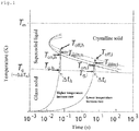
- FIG. 1 shows relations between metallic glass material states with respect to temperature and elapsed time of heating.
- a solid metallic glass material by being heated to a temperature surpassing a glass transition temperature ( T g ), becomes a supercooled liquid, and by being heated to a temperature surpassing a crystallization initiation temperature ( T on ), starts to crystallize, and is completely crystallized at a crystallization completion temperature ( T off ), eventually giving a crystalline alloy represented by the same composition as that of the metallic glass material.
- T g glass transition temperature
- T on crystallization initiation temperature
- T off crystallization completion temperature
- the application of a higher temperature increase rate brings about the supercooled state at a glass transition temperature T g,h , and allows the crystallization process to start at T on,h ; and the application of a lower temperature increase rate brings about the supercooled state at a glass transition temperature T g,l , and allows the crystallization process to start at T on,l ( ⁇ T on,h ).
- Dispersion of solid particles in viscous fluid caused by the initiation of the crystallization process at T on contributes to the increase in viscosity coefficient, which is, however, surpassed by the decrease in the viscosity coefficient of the remaining supercooled liquid due to the temperature increase, which lowers the viscosity coefficient as a whole.
- a further temperature increase causes the increase in volume of the solid particles, leading to the increase in the viscosity coefficient.
- This increase in the viscosity coefficient equilibrates with the decrease in the viscosity coefficient presented by the remaining supercooled liquid, at a temperature T min (hereinafter, referred to as "minimum viscosity coefficient temperature”), at which a minimum viscosity coefficient ⁇ ( T min ) is reached.
- T min hereinafter, referred to as "minimum viscosity coefficient temperature”
- Non-Patent Literature 4 it is known that supercooled metallic glass materials subjected to a higher temperature have a lower viscosity coefficient. This is because, as shown in FIG.1 , the higher temperature increase rate shifts the glass transition temperature of the material toward the higher temperature/shorter elapsed time side. The same tendency applies to the crystallization initiation temperature T on , which is positioned higher than the glass transition temperature, and to the minimum viscosity coefficient temperature T min , which is positioned much higher than that.
- the process for producing a molded material according to the present invention involves heating a supercooled metallic glass material lying under a temperature which is equal to or higher than its glass transition temperature to a temperature which is equal to or higher than its crystallization initiation temperature, and molding the metallic glass material, at a lower viscosity, for a period of time lasting before the completion of the crystallization process, into the material having a mixed phase of metallic glass and a crystalline phase or having a crystalline phase alone.
- This configuration enables the molding to be performed with a highly precise shape control, giving rise to a molded material with a fine structure measuring not more than tens of micrometers, such as G 2 diffraction gratings for neutron Talbot interferometers and X-ray Talbot interferometers.
- ⁇ t h is a period of time passed in the case of the application of a higher temperature increase rate (period of time passed until the arrival at crystallization completion temperature T off,h - period of time passed until the arrival at glass transition temperature T g,h )
- ⁇ t l is a period of time passed in the case of the application of a lower temperature increase rate (period of time passed until the arrival at crystallization completion temperature T off,l - period of time passed until the arrival at glass transition temperature T g,l ).
- the production time is shortened by the application of a higher temperature increase rate.
- Contribution to the molding operation achievable on a larger scale in a shorter period of time is made by the decrease in the viscosity coefficient rather than the shortening of molding time attributable to the higher temperature increase rate.
- the heating step at which a supercooled metallic glass material is heated to a temperature which is equal to or higher than its crystallization initiation temperature, is performed at a heating temperature that is preferably the minimum viscosity coefficient temperature or higher, and more preferably the crystallization completion temperature or higher, in view of the easiness of molding and the molding time.
- the heating step is performed preferably at a temperature increase rate of 0.5 K/s or more.
- the temperature increase rate is more preferably 3 K/s or more.
- a higher temperature increase rate in these cases elevates a temperature reached at a supercooled state, which lowers a minimum viscosity coefficient of the metallic glass material. This is the reason why the metallic glass material can undergo the molding operation at a much lower viscosity coefficient.
- the molding step preferred is subjecting the metallic glass material to transfer molding with the use of a concave-convex mold.
- the use of a mold in this case enables a precise shape control in producing the molded material, the material being produced with a desired shape in a relatively short period of time.
- the concave-convex mold has concavity-convexity that may be arranged either regularly or irregularly.
- the concave-convex mold has concavity-convexity that may be arranged continuously in one direction while having concavity-convexity repeatedly appear in a direction perpendicular thereto, or has concavity-convexity that may appear repeatedly in two directions perpendicular to each other.
- the use of the mold having periodic concavity-convexity would be able to produce wavefront control elements having periodic concavity-convexity.
- the heating step is performed at a temperature increase rate which is equal to or higher than a temperature increase rate ⁇ , which is obtained from a formula below, wherein ⁇ L is a depth of concavity of the above-described mold used in the molding step; d is an aperture width of the concavity; P is a pressure applied in the molding step; ⁇ is a temperature increase rate in the molding step; T min is a minimum viscosity coefficient temperature at a supercooled liquid state of the metallic glass material; ⁇ ( T min ) is a viscosity coefficient at the T min of the metallic glass material; k is Boltzmann's constant; Q is an activation energy given in the approximation of the temperature dependence of the viscosity coefficient of a supercooled liquid of the metallic glass component to Arrhenius thermal activation; and A is a constant determined by a composition of an alloy and the temperature increase rate (A>1.5).
- the heating step performed in the above manner produces molded materials with a desired concavity-convexity shape, with certainty and accuracy.
- Formula (2) is a differential equation.
- Formula (2) results in deriving a viscous flow amount ⁇ L ( T min ), from T g to T min , as Formula (4).
- ⁇ ⁇ 0 exp Q kT
- Formula 4 ⁇ ⁇ L T min ⁇ Pd 2 16 ⁇ ⁇ ⁇ ⁇ T min ⁇ kT min 2 Q 1 2
- the depth of the concavity of the mold, ⁇ L refers to a height difference between the tip of the convexity of the mold and the deepest part of the concavity of the mold; and the aperture width of the concavity, d , in the case where concavities have a width (pitch between one inner wall and the other inner wall opposite thereto) varying in the depth direction, is an averaged width in the depth direction of the concavity.
- the metallic glass material may be composed of a Gd-based, Sm-based, Eu-based or Dy-based metallic glass material.
- the metallic glass material is preferably composed of Gd w Cu x Al y B z wherein w, x, y, z are each an atomic percentage satisfying 50 ⁇ w ⁇ 80, 10 ⁇ x ⁇ 50, 0 ⁇ y ⁇ 30 and 0 ⁇ z ⁇ 10.
- the molded material allows the molded material to be produced with a fine structure having a precisely controlled shape measuring not more than tens of micrometers, leading to the precise production of G 2 diffraction gratings for neutron Talbot interferometers.
- the metallic glass material may be composed of a Pt-based, Au-based, Pd-based or Ni-based metallic glass material.
- compositions allow the molded material to be produced with a fine structure having a precisely controlled shape measuring not more than tens of micrometers, leading to the precise production of G 2 diffraction gratings for X-ray Talbot interferometers.
- the molded material according to the present invention which is given by claim 7 is composed of an alloy with the same composition as a composition of the metallic glass material, and has on its surface concavity-convexity with a pitch between adjacent convexities being in the order of nanometers or in the order of micrometers and a depth of the concavity being more than 10 ⁇ m.
- the molded material according to the present invention due to having a structure in which a pitch between adjacent convexities is in the order of nanometers or in the order of micrometers and a depth of the concavity is more than 10 ⁇ m, is employable in applications requiring fine structures measuring not more than tens of micrometers.
- a molded material having periodic concavity-convexity for example, is employable as a wavefront control element.
- Such a molded material composed of an alloy with the same composition as a composition of a Gd-based, Sm-based, Eu-based or Dy-based metallic glass material is employable as a diffraction grating for a neutron beam interferometer.
- Such a molded material composed of an alloy with the same composition as a composition of a Pt-based, Au-based, Pd-based or Ni-based metallic glass material is employable as a diffraction grating for an X-ray interferometer.
- a molded material that fulfills the above-mentioned requirements and in addition defines a depth of concavity as not more than 110 ⁇ m and the concavity-convexity period as ranging from 0.4 ⁇ m to 90 ⁇ m is employable as a G 2 diffraction grating for a neutron Talbot interferometer or an X-ray Talbot interferometer.
- This diffraction grating may have concavity with not less than a depth of 1 ⁇ m or not less than a depth of 15 ⁇ m.
- the present invention provides process for producing molded material by which a metallic glass material can be molded at a lower viscosity coefficient and a structure measuring not more than tens of micrometers can be molded with a highly precise shape control in a relatively short period of time; and the molded material, a wavefront control element and a diffraction grating are also provided.
- Process for producing molded material of embodiments of the present invention is a process which uses a metallic glass material to produce a molded material, a wavefront control element and a diffraction grating, which are embodiments of the present invention, and the process includes a heating step and a molding step.
- the heating step is a step of heating a supercooled metallic glass material or solid metallic glass material to a temperature which is equal to or higher than a temperature at which a supercooled liquid of the metallic glass material starts to crystallize, in which the heating is performed at a temperature increase rate of 0.5 K/s or more. to less than 100 K/s.
- the molding step is a step performed during the heating step in which the metallic glass material is molded, for a period of time starting with the arrival at the glass transition temperature and lasting before a completion of a crystallization process of the supercooled liquid of the metallic glass material, into a material having a mixed phase of metallic glass and a crystalline phase or having a crystalline phase alone.
- the metallic glass material is preferably subjected to transfer molding using a concave-convex mold.
- a composition of the metallic glass material is selected preferably considering a target molded material.
- the metallic glass material is preferably a Gd-based, Sm-based, Eu-based or Dy-based one in view of the capability of Gd, Sm, Eu, Dy to absorb thermal neutrons better than other elements.
- Such a metallic glass material may be the one that contains at least one component selected from Gd, Sm, Eu and Dy at an atomic ratio of 50% or more and at least one element capable of forming a eutectic crystal together with any of those elements that is selected from, for example, Ag, Al, Au, B, Bi, Cd, Co, Cu, Fe, Ga, Ge, Hg, In, Ir, Mg, Mn, Ni, Pb, Pd, Pt, Rh, Ru, Sb, Si, Sn, Te, Tl, Zn and Zr.
- B which is capable of efficiently absorbing neutrons, in an amount not detrimental to the glass formability and the thermal stability at a supercooled liquid state.
- the metallic glass material is preferably a Pt-based, Au-based, Pd-based or Ni-based one, in view of the capability of Pt, Au, Pd, Ni to absorb X-rays better than other elements.
- Such a metallic glass material may be the one that contains at least one component selected from Pt, Au, Pd and Ni at an atomic ratio of 50% or more and at least one component capable of forming a eutectic alloy system together with any of those elements that is selected from, for example, Al, Am, As, B, Be, Bi, Ca, Ce, Cm, Er, Eu, Ga, Gd, Ge, Hf, Ho, In, La, Lu, Nb, Nd, P, Pb, Pr, Sb, Sc, Se, Si, Sn, Sr, Ta, Tb, Te, Th, Ti, Tm, Y, Yb and Zr.
- the metallic glass material may take any form: for example, may be composed of a material given by directly supercooling an alloy liquid, or a metallic glass ribbon or metallic glass thin film given by rapidly quenching and solidifying an alloy liquid or by rapidly quenching and solidifying an alloy gas.
- the metallic glass material may be a metallic glass sheet given by thermal-spraying metallic glass powder prepared by an atomizing method. Crystalline substances with such a size or in such an amount as will not significantly inhibit the viscous flow of the supercooled liquid may be dispersed within the supercooled liquid or within its original metallic glass that has not been heated.
- a mold used for the transfer molding in the molding step may be the one that has concavity-convexity arranged either regularly or irregularly.
- the mold may have concavity and convexity arranged continuously in one direction while having concavity-convexity repeatedly appear in a direction perpendicular thereto, or have convexity-convexity repeatedly in two directions perpendicular to each other.
- use of the mold having periodic concavity-convexity is preferred.
- the process for producing molded material of an embodiment of the present invention involves heating a supercooled metallic glass material lying under a temperature which is equal to or higher than its glass transition temperature to a temperature which is equal to or higher than its crystallization initiation temperature, and molding the metallic glass material at a lower viscosity, during the heating, for a period of time lasting before the completion of the crystallization process, into the material having a mixed phase of metallic glass and a crystalline phase or having a crystalline phase alone.
- This configuration enables a highly precise shape control at the time of the molding, giving rise to the molded material with a fine structure measuring not more than tens of micrometers, such as G 2 diffraction gratings for neutron Talbot interferometers and X-ray Talbot interferometers.
- the process for producing molded material of embodiments of the present invention requires the metallic glass material to be molded while metallic glass material keeps a supercooled state, which inevitably shortens the production time.
- increasing a temperature increase rate in the heating step elevates a temperature reached at a supercooled state, which in turn decreases a minimum viscosity coefficient of the metallic glass materials.
- This configuration enables the metallic glass materials to be molded at a lower viscosity coefficient.
- Subjecting the metallic glass materials to transfer molding with the use of a mold gives the molded materials a precisely controlled shape.
- the molded materials are produced with a desired shape in a relatively short period of time.
- a rapidly-quenched ribbon of metallic glass material Gd 60 Cu 25 Al 15 (at.%) was subjected to temperature increase at a constant rate of 0.67 K/s, during which the temperature dependence of the viscosity coefficient of the metallic glass material was measured.
- the measurement result is shown in FIG. 3 .
- a metallic glass material used was a rapidly-quenched ribbon of Gd 60 Cu 25 Al 15 (at.%).
- the solid metallic glass material while being heated at a constant temperature increase rate of not less than 3 K/s to a temperature which is equal to or higher than its crystallization initiation temperature (580 K), was subjected to transfer molding for a period of time starting with the arrival at the glass transition temperature of the metallic glass material and lasting before the arrival at the crystallization completion temperature of the metallic glass material.
- the transfer molding was performed with a configuration as shown in Fig. 4 : on the surface of a Si wafer 11, a C sheet 12 was put, and thereon a Si mold 13 with concavity-convexity regularly arranged was put such that the concavity-convexity faced upward, and on the mold 13, a metallic glass material 14 ribbon was put, and pressure was applied at the time of molding so as to press the metallic glass material 14 to the mold 13.
- the same operation was adopted for transfer molding operations carried out in examples provided below.
- FIG.6 shows the result of an X-ray diffraction of the resultant molded metal (diffraction grating) shown in FIG. 5(a).
- FIG. 6 verifies the formation of an alloy from the metallic glass raw material. It is considered from the results of FIG. 5 and FIG. 6 that the resultant diffraction gratings having periodic concavity-convexity and composed of a Gd-based alloy are optimal for G 2 diffraction gratings for neutron Talbot interferometers.
- the process for producing molded material of an embodiment of the present invention was applied to produce a diffraction grating for X-rays.
- a metallic glass material used was a rapidly-quenched ribbon of Pt 60 Ni 15 P 25 (at.%).
- the solid metallic glass material while being heated at an average temperature increase rate of not less than 2.5 K/s to a temperature (620 to 630 K) higher than its crystallization initiation temperature (570 K), was subjected to transfer molding for a period of time starting with the arrival at the glass transition temperature of the metallic glass material and lasting before the arrival at the crystallization completion temperature of the metallic glass material.
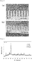
- FIG. 7(a) shows a diffraction grating that was produced at an average temperature increase rate of 2.5 K/s and at a pressure applied at the transfer molding of 5 kN, and that has concavity whose depth is 100 ⁇ m with a pitch between adjacent convexities (width of concavity) being about 10 ⁇ m and a concavity-convexity period being about 65 ⁇ m.
- a period of time from the initiation of temperature increase until the completion of the transfer molding was about 140 seconds.
- FIG. 7(b) shows a diffraction grating that was produced at an average temperature increase rate of 3.4 K/s and at a pressure applied at the transfer molding of 2 kN, and that has concavity whose depth is 50 ⁇ m with a pitch between adjacent convexities (width of concavity) being about 20 ⁇ m and a concavity-convexity period being about 84 ⁇ m.
- a period of time from the initiation of temperature increase until the completion of the transfer molding was about 380 seconds.
- FIG. 7(c) shows a diffraction grating that was produced at an average temperature increase rate of 3.2 K/s and at a pressure applied at the transfer molding of 1 kN, and that has concavity whose depth is 50 ⁇ m with a pitch between adjacent convexities (width of concavity) being about 8 ⁇ m and a concavity-convexity period being about 67 ⁇ m.
- a period of time from the initiation of temperature increase until the completion of the transfer molding was about 480 seconds.
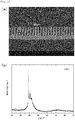
- FIG. 8 shows the result of X-ray diffraction for the resultant molded metal (diffraction grating) shown in FIG. 7(a) .
- FIG. 8 verifies the formation of an alloy from the metallic glass raw material. It is considered from the results of FIG. 7 and FIG. 8 that the resultant diffraction gratings having periodic concavity-convexity and composed of a Pt-based alloy are optimal for G 2 diffraction gratings for X-ray Talbot interferometers.
- the process for producing molded material of an embodiment of the present invention was applied to produce a diffraction grating for X-rays.
- a metallic glass material used was prepared by stacking three rapidly-quenched ribbons of Pd 42.5 Ni 7.5 Cu 30 P 20 (at.%).
- the solid metallic glass material (thickness: not more than 120 ⁇ m), while being heated at an average temperature increase rate of 5 K/s to a temperature (623 K) higher than its crystallization initiation temperature (610 K), was subjected to transfer molding for a period of time starting with the arrival at the glass transition temperature of the metallic glass material and lasting before the arrival at the crystallization completion temperature of the metallic glass material.
- FIG. 9(a) shows that the resultant diffraction grating had concavity whose depth was 60 ⁇ m with a pitch between adjacent convexities (width of concavity) being about 5 ⁇ m, and a concavity-convexity period being about 10 ⁇ m.
- a pressure at the time of the transfer molding was 20 MPa, and a period of time from the initiation of temperature increase until the completion of the transfer molding was about 180 seconds.
- FIG. 9(b) The result of X-ray diffraction for the resultant molded metal (diffraction grating) is shown in FIG. 9(b).
- FIG. 9(b) verifies the formation of an alloy from the metallic glass raw material. It is considered from the results of FIG. 9(a) and (b) that the resultant diffraction gratings having periodic concavity-convexity and composed of a Pt-based alloy are optimal for G 2 diffraction gratings for X-ray Talbot interferometers.
- the process for producing molded material of an embodiment of the present invention was applied to produce a diffraction grating for X-rays.
- a metallic glass material used was a rapidly-quenched ribbon of Pd 42.5 Ni 7.5 Cu 30 P 20 (at.%) (average thickness: 40 ⁇ m).
- the solid metallic glass material while being heated by laser at an average temperature increase rate of 1.67 K/s to a temperature (603 K) higher than its crystallization initiation temperature (590 K), was subjected to transfer molding for a period of time starting with the arrival at the glass transition temperature of the metallic glass material and lasting before the arrival at the crystallization completion temperature of the metallic glass material.
- FIG. 10(a) shows that the diffraction grating produced through laser heating had concavity whose depth was 30 ⁇ m with a pitch between adjacent convexities (width of concavity) being about 4 ⁇ m and a concavity-convexity period being about 10 ⁇ m.
- a pressure applied at the time of the transfer molding was 40 MPa, and a period of time from the initiation of temperature increase until the completion of the transfer molding was about 100 seconds.
- FIG. 10(b) The result of X-ray diffraction for the resultant molded metal (diffraction grating) is shown in FIG. 10(b).
- FIG. 10(b) verifies the formation of an alloy from the metallic glass raw material even in the case of laser heating. It is considered from the results of FIG. 10(a) and (b) that the resultant diffraction gratings having periodic concavity-convexity and composed of a Pt-based alloy are optimal for G 2 diffraction gratings for X-ray Talbot interferometers.
- the process for producing molded material of an embodiment of the present invention was applied to produce a diffraction grating for X-rays.
- a metallic glass material used was a bulk of Ni 50 Pd 30 P 20 (at.%) (thickness: 1.5 mm, diameter: 30 mm).
- the solid metallic glass material while being heated at an average temperature increase rate of 0.67 K/s to a temperature (675 K) higher than its crystallization initiation temperature (668 K), was subjected to transfer molding for a period of time starting with the arrival at the glass transition temperature of the metallic glass material and lasting before the arrival at the crystallization completion temperature of the metallic glass material.
- FIG. 11(a) shows the resultant diffraction grating having a columnar convexity with a diameter of 187 nm on a lattice point of a hexagonal lattice with a length of its one side measuring about 450 nm.
- a pressure applied at the time of the transfer molding was 20 MPa, and a period of time from the initiation of temperature increase until the completion of the transfer molding was about 180 seconds.
- FIG. 11(b) The result of an X-ray diffraction for the resultant molded metal (diffraction grating) is shown in FIG. 11(b).
- FIG. 11(b) verifies the formation of an alloy from the metallic glass raw material. It is considered from the results of FIG. 11(a) and (b) that the resultant diffraction gratings having periodic concavity-convexity and composed of a Ni-based alloy are optimal for G 2 diffraction gratings for X-ray Talbot interferometers.
Landscapes
- Chemical & Material Sciences (AREA)
- Engineering & Computer Science (AREA)
- Materials Engineering (AREA)
- Mechanical Engineering (AREA)
- Metallurgy (AREA)
- Organic Chemistry (AREA)
- Physics & Mathematics (AREA)
- Crystallography & Structural Chemistry (AREA)
- Thermal Sciences (AREA)
- Biochemistry (AREA)
- Health & Medical Sciences (AREA)
- Life Sciences & Earth Sciences (AREA)
- Analytical Chemistry (AREA)
- General Health & Medical Sciences (AREA)
- General Physics & Mathematics (AREA)
- Immunology (AREA)
- Pathology (AREA)
- General Engineering & Computer Science (AREA)
- Spectroscopy & Molecular Physics (AREA)
- High Energy & Nuclear Physics (AREA)
- Analysing Materials By The Use Of Radiation (AREA)
- Diffracting Gratings Or Hologram Optical Elements (AREA)
Description
- The present invention relates to process for producing molded material, molded materials, wavefront control elements and diffraction gratings.
- It is necessary in e.g., X-ray interferometers and neutron interferometers to precisely control the wavefront of X-rays and neutron beams. For this necessity, wavefront control elements used need to have a precisely controlled accurate shape. The wavefront control elements used in particular for X-ray Talbot interferometers and neutron Talbot interferometers are diffraction gratings. To provide diffraction gratings that have enhanced sensitivity and spatial resolution, diffraction gratings with a shorter period and a highly-precise shape have been demanded.
- A diffraction grating for X-ray Talbot interferometers that is conventionally obtained by the present inventors is one made from metallic glass which is produced by subjecting a supercooled Pd-based metallic glass material to transfer molding at a temperature increase rate of 0.33 K/s and as a result has concavity with a depth of about 10 µm and a concavity-convexity period of 8 µm (see, for example, Non-Patent Literature 1). This diffraction grating is produced with reference to an amorphous alloy production process (described in, for example, Patent Literature 1) which involves heating an amorphous alloy material at a temperature increase rate of 100 K/s or more to a temperature falling in a range between a glass transition temperature (T g) and a crystallization temperature (T x), and at the temperature in that range the amorphous alloy material is molded into a supercooled amorphous alloy material, which is then cooled to produce the amorphous alloy.
- A process developed for obtaining diffraction gratings for neutron Talbot interferometers involves injecting Gadox (Gd sulfate) powder into a Si substrate grating to allow the powder to penetrate into the substrate grating, followed by solidification, in order to produce a Gadox diffraction grating (see, for example, Non-Patent Literature 2). The diffraction grating obtained by this process has concavity with a depth of 500 µm and a concavity-convexity period of 477 µm.
- A process developed for obtaining diffraction gratings with a shorter period involves spraying Gd vapor from upward obliquely onto a Si diffraction grating mold to deposit the Gd vapor on the Si mold in order to produce a Gd diffraction grating (see, for example, Non-Patent Literature 3). The diffraction grating obtained by this process has concavity with a depth of about 11 µm and a concavity-convexity period of about 4 µm.
- Meanwhile, in heating a La-Al-Ni-based metallic glass material lying at a supercooled state at a prescribed temperature increase rate, the application of a higher temperature increase rate has been known to lead to a lower minimum viscosity coefficient of the material, i.e., a lower viscosity coefficient of the material lying immediately before arriving at a crystallization temperature (see, for example, Non-Patent Literature 4).
-
- Non-Patent Literature 1: Wataru Yashiro, Daiji Noda, Tadashi Hattori, Kouichi Hayashi, Atsushi Momose, and Hidemi Kato, "A metallic glass grating for X-ray grating interferometers fabricated by imprinting", Applied Physics Express, 2014, 7, 032501
- Non-Patent Literature 2: J. Kim, et al., "Fabrication and characterization of the source grating for visibility improvement of neutron phase imaging with gratings", Rev. Sci. Instrum., 2013, 84, 063705
- Non-Patent Literature 3: C. Grunzweig, et al., "Design, fabrication, and characterization of diffraction gratings for neutron phase contrast imaging", Rev. Sci. Instrum., 2008, 79, 053703
- Non-Patent Literature 4: Saotome et al., "Characteristic behavior of La55Al25Ni20 amorphous alloy under rapid heating", Mater. Sci. Eng., A304-306, 2001, p.743-746
- Patent Literature 1:
JP-A-H07-26354 - Performing the processes described in
Non-Patent Literature 1 andPatent Literature 1 to obtain metallic glass diffraction gratings, however, would require a temperature during the molding to be maintained in a range between a glass transition temperature (T g) and a crystallization initiation temperature (T on). In other words, the temperature increase needs to end before arriving at the crystallization initiation temperature in order to prevent the metallic glass material from advancing toward crystallization. The application of a higher temperature increase rate together with a higher proximity to the crystallization temperature (crystallization initiation temperature) is known to lead to a lower viscosity coefficient of a supercooled metallic glass material, as described in Non-PatentLiterature 4. Thus, to facilitate the molding of metallic glass materials, it would be preferred for the molding to be performed at a higher temperature increase rate with temperature being as close to the crystallization initiation temperature as possible. Yet, the application of a temperature increase rate as high as 100 K/s or more would make it difficult to end the temperature increase at a desired temperature, and shorten a lifetime spanning from the crystallization of the supercooled liquid until its stabilization. In view of this, the attempt to allow the material to avoid its crystallization and maintain a metallic glass state even after the molding operation would make it necessary to end the temperature increase well before the crystallization initiation temperature for the molding operation, for safety reasons, followed by rapidly cooling to a temperature T g or lower. Hence, the problem with the processes described in Non-PatentLiterature 1 andPatent Literature 1 is the need to mold metallic glass materials which still have a higher viscosity coefficient than cases permitting the temperature increase to continue to immediately before the crystallization initiation temperature. - The diffraction grating production process described in Non-Patent
Literature 2 can only produce diffraction gratings with a structure measuring hundreds of micrometers at smallest, making it difficult to produce diffraction gratings with a finer structure. While the process of Non-PatentLiterature 2 allows for the production of G0 (Source Grating) diffraction gratings, which have a relatively longer concavity-convexity period, this process fails to serve as producing G2 (Analyzer Grating) diffraction gratings, which have a relatively shorter concavity-convexity period. - The diffraction grating production process described in
Non-Patent Literature 3 gives diffraction gratings with a short period that are applicable to G2 diffraction gratings for neutron Talbot interferometers, and yet their shape fails to be precisely controlled: the resultant diffraction gratings have convexity with an uneven thickness, possibly causing the interferometers to have a lowered spatial resolution. Another problem with this production process is a prolonged production time ranging from about two days to one week for the production of a single diffraction grating. - The present invention, having focused on such problems as described above, has objects of providing process for producing molded material by which a metallic glass material can be molded at a lower viscosity coefficient and a structure measuring not more than tens of micrometers can be molded with a highly precise shape control in a relatively short period of time; and providing the molded material, a wavefront control element and a diffraction grating.
- The X-ray and neutron beam absorption capability of the materials of diffraction gratings, for example, is hardly affected by a structure formed by atoms in those materials, i.e., whether the materials have a crystalline state structure or an amorphous state structure. Metallic glass, which normally has superior mechanical properties such as high strength and low Young's modulus, comes to be brittle with the progress of a crystallization process. Hence, practical applications taking advantage of those superior mechanical properties inherent in the metallic glass would require a metallic glass state to be maintained even after the metallic glass undergoes the molding operation. In applications such as diffraction gratings for X-ray interferometers and neutron interferometers, on the other hand, those superior mechanical properties are not necessarily required in use, and therefore, the present inventors have thought, the maintenance of the metallic glass state may be disregarded. Based on this idea, the present inventors have discovered that the attempt to provide the diffraction gratings and such others would be advantageous by letting the crystallization process proceed during the molding operation to utilize a lower viscosity coefficient state during the molding as well as by utilizing, for the molding, a viscous flow deformation obtainable on a large scale for a period of time starting with the initiation of the crystallization process and lasting before the completion of the crystallization process. The present invention has been made based on this discovery.
- Specifically, objects described above are attained by a process as given in
claim 1 for producing a molded material according to the present invention, which comprises a step of heating a supercooled metallic glass material to a temperature which is equal to or higher than a temperature at which a supercooled liquid of the metallic glass material starts to crystallize; and a step of molding the metallic glass material, during the heating, for a period of time lasting before a completion of the crystallization process of the supercooled liquid of the metallic glass material, into the material having a mixed phase of metallic glass and a crystalline phase or having a crystalline phase alone. - The process for producing a molded material according to the present invention may comprise a step of heating a solid metallic glass material to a temperature which is equal to or higher than a glass transition temperature of the metallic glass material and is equal to or higher than a temperature at which the metallic glass material starts to crystallize; and a step of molding the metallic glass material, during the heating, for a period of time starting with an arrival at the glass transition temperature and lasting before a completion of the crystallization process of a supercooled liquid of the metallic glass material, into the material having a mixed phase of metallic glass and a crystalline phase or having a crystalline phase alone.
- The processes for producing a molded material according to the present invention are based on principle set forth below.
-
FIG. 1 shows relations between metallic glass material states with respect to temperature and elapsed time of heating. As shown inFIG. 1 , a solid metallic glass material, by being heated to a temperature surpassing a glass transition temperature (T g), becomes a supercooled liquid, and by being heated to a temperature surpassing a crystallization initiation temperature (T on), starts to crystallize, and is completely crystallized at a crystallization completion temperature (T off), eventually giving a crystalline alloy represented by the same composition as that of the metallic glass material. The above excludes effects brought about by factors occurring during the temperature increase/decrease step: impurities such as oxygen mixed unintendedly and constituent elements lost due to e.g., evaporation. - In an instance shown in
FIG. 1 , the application of a higher temperature increase rate brings about the supercooled state at a glass transition temperature T g,h, and allows the crystallization process to start at T on,h; and the application of a lower temperature increase rate brings about the supercooled state at a glass transition temperature T g,l, and allows the crystallization process to start at T on,l (<T on,h). Dispersion of solid particles in viscous fluid caused by the initiation of the crystallization process at T on contributes to the increase in viscosity coefficient, which is, however, surpassed by the decrease in the viscosity coefficient of the remaining supercooled liquid due to the temperature increase, which lowers the viscosity coefficient as a whole. And yet, a further temperature increase causes the increase in volume of the solid particles, leading to the increase in the viscosity coefficient. This increase in the viscosity coefficient equilibrates with the decrease in the viscosity coefficient presented by the remaining supercooled liquid, at a temperature T min (hereinafter, referred to as "minimum viscosity coefficient temperature"), at which a minimum viscosity coefficient η(T min) is reached. The viscosity coefficient as a whole, even if that temperature is surpassed or maintained, would continue to rise because of a more pronounced contribution made by the increase in volume of the solid particles mentioned above in a longer period of time. Eventually, the completion of the crystallization process terminates the viscous flow, giving a crystalline solid. It is notable here that the increase of the viscosity coefficient lasting from its minimum value toward its higher value is still accompanied by the occurrence of the viscous flow; namely, the viscous molding operation can be continued for a period of time that ends at the completion of the crystallization process. - As described in Non-Patent
Literature 4, it is known that supercooled metallic glass materials subjected to a higher temperature have a lower viscosity coefficient. This is because, as shown inFIG.1 , the higher temperature increase rate shifts the glass transition temperature of the material toward the higher temperature/shorter elapsed time side. The same tendency applies to the crystallization initiation temperature T on, which is positioned higher than the glass transition temperature, and to the minimum viscosity coefficient temperature T min, which is positioned much higher than that. Given T on,h>T on,l and T min,h>T min,l, the application of a higher temperature increase rate, rather than the application of a lower temperature increase rate, leads to a lowered viscosity coefficient η(T on) of the metallic glass material at the crystallization initiation temperature T on, and also leads to a lowered minimum viscosity coefficient η(T min) occurring in the crystallization process. - The process for producing a molded material according to the present invention involves heating a supercooled metallic glass material lying under a temperature which is equal to or higher than its glass transition temperature to a temperature which is equal to or higher than its crystallization initiation temperature, and molding the metallic glass material, at a lower viscosity, for a period of time lasting before the completion of the crystallization process, into the material having a mixed phase of metallic glass and a crystalline phase or having a crystalline phase alone. This configuration enables the molding to be performed with a highly precise shape control, giving rise to a molded material with a fine structure measuring not more than tens of micrometers, such as G2 diffraction gratings for neutron Talbot interferometers and X-ray Talbot interferometers.
- The process for producing a molded material according to the present invention requires the metallic glass material to be subjected to the molding operation while the metallic glass material keeps its supercooled state, inevitably shortening the production time. As shown in
FIG. 1 , in a period of time during which the metallic glass material keeps its supercooled state, Δth<Δt l is fulfilled wherein Δt h is a period of time passed in the case of the application of a higher temperature increase rate (period of time passed until the arrival at crystallization completion temperature T off,h - period of time passed until the arrival at glass transition temperature T g,h), and Δt l is a period of time passed in the case of the application of a lower temperature increase rate (period of time passed until the arrival at crystallization completion temperature T off,l - period of time passed until the arrival at glass transition temperature T g,l). Thus, the production time is shortened by the application of a higher temperature increase rate. Contribution to the molding operation achievable on a larger scale in a shorter period of time is made by the decrease in the viscosity coefficient rather than the shortening of molding time attributable to the higher temperature increase rate. - In the process for producing a molded material according to the present invention, the heating step, at which a supercooled metallic glass material is heated to a temperature which is equal to or higher than its crystallization initiation temperature, is performed at a heating temperature that is preferably the minimum viscosity coefficient temperature or higher, and more preferably the crystallization completion temperature or higher, in view of the easiness of molding and the molding time.
- In the process for producing the molded material according to the present invention, the heating step is performed preferably at a temperature increase rate of 0.5 K/s or more. The temperature increase rate is more preferably 3 K/s or more. A higher temperature increase rate in these cases elevates a temperature reached at a supercooled state, which lowers a minimum viscosity coefficient of the metallic glass material. This is the reason why the metallic glass material can undergo the molding operation at a much lower viscosity coefficient.
- In the process for producing a molded material according to the present invention, the molding step preferred is subjecting the metallic glass material to transfer molding with the use of a concave-convex mold. The use of a mold in this case enables a precise shape control in producing the molded material, the material being produced with a desired shape in a relatively short period of time. The concave-convex mold has concavity-convexity that may be arranged either regularly or irregularly. The concave-convex mold has concavity-convexity that may be arranged continuously in one direction while having concavity-convexity repeatedly appear in a direction perpendicular thereto, or has concavity-convexity that may appear repeatedly in two directions perpendicular to each other. The use of the mold having periodic concavity-convexity would be able to produce wavefront control elements having periodic concavity-convexity.
- In the use of the above-described mold, it is preferred for the heating step to be performed at a temperature increase rate which is equal to or higher than a temperature increase rate β, which is obtained from a formula below, wherein ΔL is a depth of concavity of the above-described mold used in the molding step; d is an aperture width of the concavity; P is a pressure applied in the molding step; β is a temperature increase rate in the molding step; T min is a minimum viscosity coefficient temperature at a supercooled liquid state of the metallic glass material; η(T min) is a viscosity coefficient at the T min of the metallic glass material; k is Boltzmann's constant; Q is an activation energy given in the approximation of the temperature dependence of the viscosity coefficient of a supercooled liquid of the metallic glass component to Arrhenius thermal activation; and A is a constant determined by a composition of an alloy and the temperature increase rate (A>1.5).
[Formula 1]
- The heating step performed in the above manner produces molded materials with a desired concavity-convexity shape, with certainty and accuracy.
- Formula (1) can be determined in a following manner. Assuming concavity of the mold to be a tube extending in its depth direction and assuming the metallic glass material to be a viscous fluid flowing within the tube leads to the fulfillment of a Hagen-Poiseuille formula. Specifically, provided that d is an inner diameter of the tube (aperture width of concavity), P is a pressure applied to the viscous fluid, η is a viscosity coefficient of the viscous fluid (metallic glass material), v is a flow velocity at the time when the viscous fluid (metallic glass material) flows within the tube, and L is a flow amount of the viscous fluid (metallic glass material), Formula (2) will be obtained as a Hagen-Poiseuille formula.
[Formula 2]

- Formula (2) is a differential equation. By neglecting a minute viscous flow amount generated within a range from room temperature to T g during the temperature increase, and by assuming the temperature dependence of the viscosity coefficient at the supercooled liquid state from T g to minimum viscosity coefficient temperature T min to be approximate to the temperature dependence defined in the Arrhenius equation represented by Formula (3), solving Formula (2) results in deriving a viscous flow amount ΔL (T min), from T g to T min, as Formula (4).
[Formula 3]
[Formula 4]
- It is generally difficult to accurately define, with a numerical formula, a total viscous flow amount ΔL present from T g to crystallization completion temperature T off, which heavily depends on the crystallization process of the supercooled liquid occurring from its midpoint T min to T off. However, using Formula (1) in view of ΔL=A·ΔL(T min), with a constant A (>1.5) given by considering the symmetry between the two crystallization processes, i.e., a process ranging from the initiation of the crystallization to the minimum viscosity state (T on to T min) and a process ranging from the minimum viscosity state to the completion of the crystallization (T min to T off), could provide the total viscous flow amount ΔL. A is a constant determined by a composition of a metallic glass alloy and a temperature increase rate.
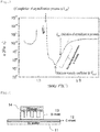
- Relations of the parameters provided in Formula (1) are shown in
FIG. 2 . In Formula (1), increase in the temperature increase rate would heighten the minimum viscosity coefficient temperature T min, according toFIG. 1 , and would lower the minimum viscosity coefficient η(T min), according toNon-Patent Literature 4. Consequently, ΔL increases. - In Formula (1), the depth of the concavity of the mold, ΔL, refers to a height difference between the tip of the convexity of the mold and the deepest part of the concavity of the mold; and the aperture width of the concavity, d, in the case where concavities have a width (pitch between one inner wall and the other inner wall opposite thereto) varying in the depth direction, is an averaged width in the depth direction of the concavity.
- In the process for producing a molded material according to the present invention, the metallic glass material may be composed of a Gd-based, Sm-based, Eu-based or Dy-based metallic glass material. In particular, the metallic glass material is preferably composed of GdwCuxAlyBz wherein w, x, y, z are each an atomic percentage satisfying 50≤w≤80, 10≤x≤50, 0≤y≤30 and 0≤z≤10. These compositions, due to the capability of Gd, Sm, Eu and Dy to absorb thermal neutrons better than other elements, are effective in terms of producing diffraction gratings for neutron beam interferometers. In particular, these compositions allow the molded material to be produced with a fine structure having a precisely controlled shape measuring not more than tens of micrometers, leading to the precise production of G2 diffraction gratings for neutron Talbot interferometers. In the process for producing a molded material according to the present invention, the metallic glass material may be composed of a Pt-based, Au-based, Pd-based or Ni-based metallic glass material. These compositions, due to the capability of Pt, Au, Pd, Ni to absorb X-rays better than other elements, are effective in terms of producing diffraction gratings for X-ray interferometers. In particular, these compositions allow the molded material to be produced with a fine structure having a precisely controlled shape measuring not more than tens of micrometers, leading to the precise production of G2 diffraction gratings for X-ray Talbot interferometers.
- The molded material according to the present invention which is given by claim 7 is composed of an alloy with the same composition as a composition of the metallic glass material, and has on its surface concavity-convexity with a pitch between adjacent convexities being in the order of nanometers or in the order of micrometers and a depth of the concavity being more than 10 µm.
- The molded material according to the present invention, due to having a structure in which a pitch between adjacent convexities is in the order of nanometers or in the order of micrometers and a depth of the concavity is more than 10 µm, is employable in applications requiring fine structures measuring not more than tens of micrometers. Such a molded material having periodic concavity-convexity, for example, is employable as a wavefront control element. Such a molded material composed of an alloy with the same composition as a composition of a Gd-based, Sm-based, Eu-based or Dy-based metallic glass material is employable as a diffraction grating for a neutron beam interferometer. Such a molded material composed of an alloy with the same composition as a composition of a Pt-based, Au-based, Pd-based or Ni-based metallic glass material is employable as a diffraction grating for an X-ray interferometer. Such a molded material that fulfills the above-mentioned requirements and in addition defines a depth of concavity as not more than 110 µm and the concavity-convexity period as ranging from 0.4 µm to 90 µm is employable as a G2 diffraction grating for a neutron Talbot interferometer or an X-ray Talbot interferometer. This diffraction grating may have concavity with not less than a depth of 1 µm or not less than a depth of 15 µm.
- The present invention provides process for producing molded material by which a metallic glass material can be molded at a lower viscosity coefficient and a structure measuring not more than tens of micrometers can be molded with a highly precise shape control in a relatively short period of time; and the molded material, a wavefront control element and a diffraction grating are also provided.
-
-
FIG. 1 is a graph showing relations between metallic glass material states with respect to temperature and elapsed time of heating. -
FIG. 2 is (a) a graph that, in heating a metallic glass material, shows a relation between a temperature T and a viscosity coefficient η of the metallic glass material, and (b) a graph that, in heating a metallic glass material, schematically shows a relation between an elapsed time of heating t and a flow amount ΔL of the metallic glass material. -
FIG. 3 is a graph that in heating a metallic glass material according to process for producing molded material of an embodiment of the present invention, shows a measurement result of a viscosity coefficient η of the metallic glass material with respect to a temperature T. -
FIG. 4 is a side-view showing how transfer molding is performed in a molding step included in process for producing molded material of an embodiment of the present invention. -
FIG. 5 shows photomicrographs of diffraction gratings produced according to process for producing molded material of an embodiment of the present invention and using a Gd60Cu25Al15 (at.%) metallic glass material, in which loads applied at the time of transfer molding are (a) 100 MPa and (b) 50 MPa. -
FIG. 6 shows an X-ray diffraction spectrum of the molded metal (diffraction grating) shown inFIG. 5(a) . -
FIG. 7 shows photomicrographs of diffraction gratings produced according to process for producing molded material of an embodiment of the present invention and using a Pt60Ni15P25 (at.%) metallic glass material, in which (a) an average temperature increase rate is 2.5 K/s and a pressure applied at the time of transfer molding is 5 kN, (b) an average temperature increase rate is 3.4 K/s and a pressure applied at the time of transfer molding is 2 kN, and (c) an average temperature increase rate is 3.2 K/s and a pressure applied at the time of transfer molding is 1 kN. -
FIG. 8 shows an X-ray diffraction spectrum of the molded metal (diffraction grating) shown inFIG. 7(a) . -
FIG. 9 shows (a) a photomicrograph and (b) an X-ray diffraction spectrum, of a molded metal (diffraction grating) produced according to process for producing molded material of an embodiment of the present invention and using a Pd42.5Ni7.5Cu30P20 (at.%) metallic glass material, in which an average temperature increase rate is 5 K/s and a pressure applied at the time of transfer molding is 20 MPa. -
FIG. 10 shows (a) a photomicrograph and (b) an X-ray diffraction spectrum, of a molded metal (diffraction grating) produced according to process for producing molded material of an embodiment of the present invention and using a Pd42.5Ni7.5Cu30P20 (at.%) metallic glass material, in which an average temperature increase rate in laser heating is 1.67 K/s and a pressure applied at the time of transfer molding is 40 MPa. -
FIG. 11 shows (a) a photomicrograph and (b) an X-ray diffraction spectrum, of a molded metal (diffraction grating) produced according to process for producing molded material of an embodiment of the present invention and using a Ni50Pd30P20 (at.%) metallic glass material, in which an average temperature increase rate is 0.67 K/s and a pressure applied at the time of transfer molding is 20 MPa. - Hereinafter, embodiments of the present invention will be described.
- Process for producing molded material of embodiments of the present invention is a process which uses a metallic glass material to produce a molded material, a wavefront control element and a diffraction grating, which are embodiments of the present invention, and the process includes a heating step and a molding step.
- The heating step is a step of heating a supercooled metallic glass material or solid metallic glass material to a temperature which is equal to or higher than a temperature at which a supercooled liquid of the metallic glass material starts to crystallize, in which the heating is performed at a temperature increase rate of 0.5 K/s or more. to less than 100 K/s.
- The molding step is a step performed during the heating step in which the metallic glass material is molded, for a period of time starting with the arrival at the glass transition temperature and lasting before a completion of a crystallization process of the supercooled liquid of the metallic glass material, into a material having a mixed phase of metallic glass and a crystalline phase or having a crystalline phase alone. At this time, the metallic glass material is preferably subjected to transfer molding using a concave-convex mold.
- A composition of the metallic glass material is selected preferably considering a target molded material. For the production of G2 diffraction gratings for neutron beam interferometers, in particular for neutron Talbot interferometers, the metallic glass material is preferably a Gd-based, Sm-based, Eu-based or Dy-based one in view of the capability of Gd, Sm, Eu, Dy to absorb thermal neutrons better than other elements. Such a metallic glass material may be the one that contains at least one component selected from Gd, Sm, Eu and Dy at an atomic ratio of 50% or more and at least one element capable of forming a eutectic crystal together with any of those elements that is selected from, for example, Ag, Al, Au, B, Bi, Cd, Co, Cu, Fe, Ga, Ge, Hg, In, Ir, Mg, Mn, Ni, Pb, Pd, Pt, Rh, Ru, Sb, Si, Sn, Te, Tl, Zn and Zr. Preferred in particular is the addition of B, which is capable of efficiently absorbing neutrons, in an amount not detrimental to the glass formability and the thermal stability at a supercooled liquid state.
- For the production of G2 diffraction gratings for X-ray interferometers, in particular for X-ray Talbot interferometers, for example, the metallic glass material is preferably a Pt-based, Au-based, Pd-based or Ni-based one, in view of the capability of Pt, Au, Pd, Ni to absorb X-rays better than other elements. Such a metallic glass material may be the one that contains at least one component selected from Pt, Au, Pd and Ni at an atomic ratio of 50% or more and at least one component capable of forming a eutectic alloy system together with any of those elements that is selected from, for example, Al, Am, As, B, Be, Bi, Ca, Ce, Cm, Er, Eu, Ga, Gd, Ge, Hf, Ho, In, La, Lu, Nb, Nd, P, Pb, Pr, Sb, Sc, Se, Si, Sn, Sr, Ta, Tb, Te, Th, Ti, Tm, Y, Yb and Zr.
- The metallic glass material may take any form: for example, may be composed of a material given by directly supercooling an alloy liquid, or a metallic glass ribbon or metallic glass thin film given by rapidly quenching and solidifying an alloy liquid or by rapidly quenching and solidifying an alloy gas. The metallic glass material may be a metallic glass sheet given by thermal-spraying metallic glass powder prepared by an atomizing method. Crystalline substances with such a size or in such an amount as will not significantly inhibit the viscous flow of the supercooled liquid may be dispersed within the supercooled liquid or within its original metallic glass that has not been heated.
- A mold used for the transfer molding in the molding step may be the one that has concavity-convexity arranged either regularly or irregularly. The mold may have concavity and convexity arranged continuously in one direction while having concavity-convexity repeatedly appear in a direction perpendicular thereto, or have convexity-convexity repeatedly in two directions perpendicular to each other. For the production of wavefront control elements and diffraction gratings that have periodic concavity-convexity, use of the mold having periodic concavity-convexity is preferred.
- Hereinafter, actions and effects will be described.
- The process for producing molded material of an embodiment of the present invention involves heating a supercooled metallic glass material lying under a temperature which is equal to or higher than its glass transition temperature to a temperature which is equal to or higher than its crystallization initiation temperature, and molding the metallic glass material at a lower viscosity, during the heating, for a period of time lasting before the completion of the crystallization process, into the material having a mixed phase of metallic glass and a crystalline phase or having a crystalline phase alone. This configuration enables a highly precise shape control at the time of the molding, giving rise to the molded material with a fine structure measuring not more than tens of micrometers, such as G2 diffraction gratings for neutron Talbot interferometers and X-ray Talbot interferometers.
- The process for producing molded material of embodiments of the present invention requires the metallic glass material to be molded while metallic glass material keeps a supercooled state, which inevitably shortens the production time. According to the process for producing molded material of embodiments of the present invention, increasing a temperature increase rate in the heating step elevates a temperature reached at a supercooled state, which in turn decreases a minimum viscosity coefficient of the metallic glass materials. This configuration enables the metallic glass materials to be molded at a lower viscosity coefficient. Subjecting the metallic glass materials to transfer molding with the use of a mold gives the molded materials a precisely controlled shape. The molded materials are produced with a desired shape in a relatively short period of time.
- A rapidly-quenched ribbon of metallic glass material Gd60Cu25Al15 (at.%) was subjected to temperature increase at a constant rate of 0.67 K/s, during which the temperature dependence of the viscosity coefficient of the metallic glass material was measured. The measurement result is shown in
FIG. 3 . - As shown in
FIG. 3 , the tens-of-K range falling before a minimum viscosity coefficient temperature T min, although somewhat affected by a viscosity increase observed in the range beginning with T on, fulfills a relation between reciprocal of temperature (1/T) and a logarithm of viscosity coefficient (logη) that takes a substantially linear form. This means that the temperature dependence of the viscosity coefficient at a supercooled state is as defined in the Arrhenius equation as represented in Formula (3). This verifies the fulfillments of the relations represented by Formula (1) and byFIG. 2 with high precision. - The process for producing molded material of an embodiment of the present invention was applied to produce a diffraction grating for neutron beams. A metallic glass material used was a rapidly-quenched ribbon of Gd60Cu25Al15 (at.%). The solid metallic glass material, while being heated at a constant temperature increase rate of not less than 3 K/s to a temperature which is equal to or higher than its crystallization initiation temperature (580 K), was subjected to transfer molding for a period of time starting with the arrival at the glass transition temperature of the metallic glass material and lasting before the arrival at the crystallization completion temperature of the metallic glass material.
- The transfer molding was performed with a configuration as shown in
Fig. 4 : on the surface of aSi wafer 11, aC sheet 12 was put, and thereon aSi mold 13 with concavity-convexity regularly arranged was put such that the concavity-convexity faced upward, and on themold 13, ametallic glass material 14 ribbon was put, and pressure was applied at the time of molding so as to press themetallic glass material 14 to themold 13. The same operation was adopted for transfer molding operations carried out in examples provided below. - As shown in
Figures 5(a) and (b) , the transfer molding operations performed with a pressure of 100 MPa and 50 MPa resulted in producing diffraction gratings whose concavity had a depth of 20 µm and 30 µm, respectively. Considering the successful filling to the depth of 30 µm at 50 MPa, the application of 100 MPa would not have been necessarily required for the molding to create a shallow depth of 20 µm, and even the application of 50 MPa would have been sufficient. These diffraction gratings had a pitch between adjacent convexities (width of concavity) of 4 µm and a concavity-convexity period of 9 µm. -
FIG.6 shows the result of an X-ray diffraction of the resultant molded metal (diffraction grating) shown inFIG. 5(a). FIG. 6 verifies the formation of an alloy from the metallic glass raw material. It is considered from the results ofFIG. 5 and FIG. 6 that the resultant diffraction gratings having periodic concavity-convexity and composed of a Gd-based alloy are optimal for G2 diffraction gratings for neutron Talbot interferometers. - The process for producing molded material of an embodiment of the present invention was applied to produce a diffraction grating for X-rays. A metallic glass material used was a rapidly-quenched ribbon of Pt60Ni15P25 (at.%). The solid metallic glass material, while being heated at an average temperature increase rate of not less than 2.5 K/s to a temperature (620 to 630 K) higher than its crystallization initiation temperature (570 K), was subjected to transfer molding for a period of time starting with the arrival at the glass transition temperature of the metallic glass material and lasting before the arrival at the crystallization completion temperature of the metallic glass material.
- The diffraction gratings produced are shown in
Figures 7(a)-(c) . -
FIG. 7(a) shows a diffraction grating that was produced at an average temperature increase rate of 2.5 K/s and at a pressure applied at the transfer molding of 5 kN, and that has concavity whose depth is 100 µm with a pitch between adjacent convexities (width of concavity) being about 10 µm and a concavity-convexity period being about 65 µm. In this instance, a period of time from the initiation of temperature increase until the completion of the transfer molding was about 140 seconds. -
FIG. 7(b) shows a diffraction grating that was produced at an average temperature increase rate of 3.4 K/s and at a pressure applied at the transfer molding of 2 kN, and that has concavity whose depth is 50 µm with a pitch between adjacent convexities (width of concavity) being about 20 µm and a concavity-convexity period being about 84 µm. In this instance, a period of time from the initiation of temperature increase until the completion of the transfer molding was about 380 seconds. -
FIG. 7(c) shows a diffraction grating that was produced at an average temperature increase rate of 3.2 K/s and at a pressure applied at the transfer molding of 1 kN, and that has concavity whose depth is 50 µm with a pitch between adjacent convexities (width of concavity) being about 8 µm and a concavity-convexity period being about 67 µm. In this instance, a period of time from the initiation of temperature increase until the completion of the transfer molding was about 480 seconds. -
FIG. 8 shows the result of X-ray diffraction for the resultant molded metal (diffraction grating) shown inFIG. 7(a) .FIG. 8 verifies the formation of an alloy from the metallic glass raw material. It is considered from the results ofFIG. 7 andFIG. 8 that the resultant diffraction gratings having periodic concavity-convexity and composed of a Pt-based alloy are optimal for G2 diffraction gratings for X-ray Talbot interferometers. - The process for producing molded material of an embodiment of the present invention was applied to produce a diffraction grating for X-rays. A metallic glass material used was prepared by stacking three rapidly-quenched ribbons of Pd42.5Ni7.5Cu30P20 (at.%). The solid metallic glass material (thickness: not more than 120 µm), while being heated at an average temperature increase rate of 5 K/s to a temperature (623 K) higher than its crystallization initiation temperature (610 K), was subjected to transfer molding for a period of time starting with the arrival at the glass transition temperature of the metallic glass material and lasting before the arrival at the crystallization completion temperature of the metallic glass material.
- The diffraction grating produced is shown in
FIG. 9(a). FIG. 9(a) shows that the resultant diffraction grating had concavity whose depth was 60 µm with a pitch between adjacent convexities (width of concavity) being about 5 µm, and a concavity-convexity period being about 10 µm. A pressure at the time of the transfer molding was 20 MPa, and a period of time from the initiation of temperature increase until the completion of the transfer molding was about 180 seconds. - The result of X-ray diffraction for the resultant molded metal (diffraction grating) is shown in
FIG. 9(b). FIG. 9(b) verifies the formation of an alloy from the metallic glass raw material. It is considered from the results ofFIG. 9(a) and (b) that the resultant diffraction gratings having periodic concavity-convexity and composed of a Pt-based alloy are optimal for G2 diffraction gratings for X-ray Talbot interferometers. - The process for producing molded material of an embodiment of the present invention was applied to produce a diffraction grating for X-rays. A metallic glass material used was a rapidly-quenched ribbon of Pd42.5Ni7.5Cu30P20 (at.%) (average thickness: 40 µm). The solid metallic glass material, while being heated by laser at an average temperature increase rate of 1.67 K/s to a temperature (603 K) higher than its crystallization initiation temperature (590 K), was subjected to transfer molding for a period of time starting with the arrival at the glass transition temperature of the metallic glass material and lasting before the arrival at the crystallization completion temperature of the metallic glass material.
- The diffraction grating produced is shown in
FIG. 10(a). FIG. 10(a) shows that the diffraction grating produced through laser heating had concavity whose depth was 30 µm with a pitch between adjacent convexities (width of concavity) being about 4 µm and a concavity-convexity period being about 10 µm. A pressure applied at the time of the transfer molding was 40 MPa, and a period of time from the initiation of temperature increase until the completion of the transfer molding was about 100 seconds. - The result of X-ray diffraction for the resultant molded metal (diffraction grating) is shown in
FIG. 10(b). FIG. 10(b) verifies the formation of an alloy from the metallic glass raw material even in the case of laser heating. It is considered from the results ofFIG. 10(a) and (b) that the resultant diffraction gratings having periodic concavity-convexity and composed of a Pt-based alloy are optimal for G2 diffraction gratings for X-ray Talbot interferometers. - The process for producing molded material of an embodiment of the present invention was applied to produce a diffraction grating for X-rays. A metallic glass material used was a bulk of Ni50Pd30P20 (at.%) (thickness: 1.5 mm, diameter: 30 mm). The solid metallic glass material, while being heated at an average temperature increase rate of 0.67 K/s to a temperature (675 K) higher than its crystallization initiation temperature (668 K), was subjected to transfer molding for a period of time starting with the arrival at the glass transition temperature of the metallic glass material and lasting before the arrival at the crystallization completion temperature of the metallic glass material.
- The diffraction grating produced is shown in
FIG. 11(a). FIG. 11(a) shows the resultant diffraction grating having a columnar convexity with a diameter of 187 nm on a lattice point of a hexagonal lattice with a length of its one side measuring about 450 nm. A pressure applied at the time of the transfer molding was 20 MPa, and a period of time from the initiation of temperature increase until the completion of the transfer molding was about 180 seconds. - The result of an X-ray diffraction for the resultant molded metal (diffraction grating) is shown in
FIG. 11(b). FIG. 11(b) verifies the formation of an alloy from the metallic glass raw material. It is considered from the results ofFIG. 11(a) and (b) that the resultant diffraction gratings having periodic concavity-convexity and composed of a Ni-based alloy are optimal for G2 diffraction gratings for X-ray Talbot interferometers. -
- 11:
- Si wafer
- 12:
- sheet
- 13:
- mold
- 14:
- metallic glass material
Claims (8)
- A process for producing a molded material comprising:a step of heating a supercooled or solid metallic glass material to a temperature which is equal to or higher than a temperature at which a supercooled liquid of the metallic glass material is completely crystallized at a temperature increase rate of 0.5 K/s or more and less than 100 K/s;and during the heating step, and for a period of time lasting before a completion of a crystallization process of the supercooled liquid of the metallic glass material, a step of molding the metallic glass material at a temperature which is equal to or higher than a glass transition temperature of the metallic glass material into the material having a mixed phase of metallic glass and a crystalline phase or having a crystalline phase alone to produce said molded material composed of an alloy which has on its surface periodic concavity-convexity, a depth of the concavity being not more than 110 µm, and the concavity-convexity period ranging from 0.4 µm to 90 µm.
- The process for producing a molded material according to claim 1, wherein
the step of molding is performed by subjecting the metallic glass material to transfer molding. - The process for producing a molded material according to any one of claims 1 or 2, wherein
the step of molding is performed to produce a wavefront control element having periodic concavity-convexity. - The process for producing a molded material according to any one of claims 1 or 2, wherein
the step of molding is performed to produce a G2 diffraction grating for a neutron Talbot interferometer or an X-ray Talbot interferometer. - The process for producing a molded material according to claim 4, wherein
the metallic glass material comprises a Gd-based, Sm-based, Eu-based, Dy-based, Pt-based, Au-based, Pd-based or Ni-based metallic glass material. - The process for producing a molded material according to claim 4, wherein
the metallic glass material is composed of GdwCuxAlyBz, wherein w, x, y, z are each an atomic percentage satisfying 50≤w≤80, 10≤x≤50, 0≤y≤30 and 0≤z≤10. - A molded material produced by the process for producing a molded material according to any one of claims 1 to 6, comprising a diffraction grating which has a mixed phase of metallic glass and a crystalline phase or has a crystalline phase alone and which has on its surface periodic concavity-convexity, a depth of the concavity being not more than 110 µm, and the concavity-convexity period ranging from 0.4 µm to 90 µm.
- The molded material according to claim 7, said molded material composed of an alloy with the same composition as a composition of a Gd-based, Sm-based, Eu-based, Dy-based, Pt-based, Au-based, Pd-based or Ni-based metallic glass material.
Applications Claiming Priority (2)
| Application Number | Priority Date | Filing Date | Title |
|---|---|---|---|
| JP2015124336 | 2015-06-22 | ||
| PCT/JP2016/068182 WO2016208517A1 (en) | 2015-06-22 | 2016-06-17 | Method for manufacturing molded material, molded material, wavefront control element, and diffraction grating |
Publications (3)
| Publication Number | Publication Date |
|---|---|
| EP3312300A1 EP3312300A1 (en) | 2018-04-25 |
| EP3312300A4 EP3312300A4 (en) | 2018-05-23 |
| EP3312300B1 true EP3312300B1 (en) | 2019-12-18 |
Family
ID=57585008
Family Applications (1)
| Application Number | Title | Priority Date | Filing Date |
|---|---|---|---|
| EP16814288.3A Active EP3312300B1 (en) | 2015-06-22 | 2016-06-17 | Method for manufacturing molded material and a molded material comprising a diffraction grating |
Country Status (4)
| Country | Link |
|---|---|
| US (1) | US10968505B2 (en) |
| EP (1) | EP3312300B1 (en) |
| JP (1) | JP6863589B2 (en) |
| WO (1) | WO2016208517A1 (en) |
Families Citing this family (4)
| Publication number | Priority date | Publication date | Assignee | Title |
|---|---|---|---|---|
| DE102017200762A1 (en) * | 2017-01-18 | 2018-07-19 | Siemens Healthcare Gmbh | Scattering grid with an amorphous material and its use in a scattered radiation grid |
| JP6968419B2 (en) * | 2018-04-27 | 2021-11-17 | 国立大学法人東北大学 | Manufacturing method of wavefront control element |
| EP3654075A1 (en) | 2018-11-13 | 2020-05-20 | Koninklijke Philips N.V. | Structured grating component, imaging system and manufacturing method |
| CN111304557B (en) * | 2020-03-20 | 2021-01-19 | 西安交通大学 | A metallic glass metamaterial with a wrinkled structure |
Family Cites Families (8)
| Publication number | Priority date | Publication date | Assignee | Title |
|---|---|---|---|---|
| JPH0726354A (en) | 1993-03-15 | 1995-01-27 | Toyota Motor Corp | Amorphous alloy forming method |
| JP3490228B2 (en) * | 1996-03-25 | 2004-01-26 | アルプス電気株式会社 | Hard magnetic alloy compact and manufacturing method thereof |
| JP2005121730A (en) * | 2003-10-14 | 2005-05-12 | Seiko Epson Corp | Reflective diffraction grating and method of manufacturing the same |
| TW200819546A (en) * | 2006-10-30 | 2008-05-01 | Jinn P Chu | In-air micro and nanoimprint of bulk metallic glasses and a method for making the same |
| CN103153502B (en) | 2010-08-31 | 2015-04-01 | 加利福尼亚技术学院 | High aspect ratio parts of bulk metallic glass and methods of manufacturing thereof |
| KR101527306B1 (en) | 2011-02-16 | 2015-06-09 | 캘리포니아 인스티튜트 오브 테크놀로지 | Injection molding of metallic glass by rapid capacitor discharge |
| JP5936487B2 (en) * | 2012-08-23 | 2016-06-22 | キヤノン株式会社 | Amorphous alloy, molding die, and optical element manufacturing method |
| US20160318095A1 (en) * | 2013-10-29 | 2016-11-03 | Yale University | Molding and De-Molding of Metallic Glass Using Non-Disposable Molds |
-
2016
- 2016-06-17 JP JP2017524878A patent/JP6863589B2/en active Active
- 2016-06-17 EP EP16814288.3A patent/EP3312300B1/en active Active
- 2016-06-17 US US15/738,929 patent/US10968505B2/en active Active
- 2016-06-17 WO PCT/JP2016/068182 patent/WO2016208517A1/en not_active Ceased
Non-Patent Citations (1)
| Title |
|---|
| None * |
Also Published As
| Publication number | Publication date |
|---|---|
| JPWO2016208517A1 (en) | 2018-05-24 |
| US20180187294A1 (en) | 2018-07-05 |
| JP6863589B2 (en) | 2021-04-21 |
| US10968505B2 (en) | 2021-04-06 |
| WO2016208517A1 (en) | 2016-12-29 |
| EP3312300A4 (en) | 2018-05-23 |
| EP3312300A1 (en) | 2018-04-25 |
Similar Documents
| Publication | Publication Date | Title |
|---|---|---|
| US10968505B2 (en) | Process for producing molded material, molded material, wavefront control element and diffraction grating | |
| US9845523B2 (en) | Methods for shaping high aspect ratio articles from metallic glass alloys using rapid capacitive discharge and metallic glass feedstock for use in such methods | |
| Yavari et al. | Crystallization during bending of a Pd-based metallic glass detected by x-ray microscopy | |
| Tainoff et al. | Competition between exciton-phonon interaction and defects states in the 3.31 eV band in ZnO | |
| Sordelet et al. | Synthesis of Cu47Ti34Zr11Ni8 bulk metallic glass by warm extrusion of gas atomized powders | |
| Sokolowski-Tinten et al. | Ultrafast phase transitions and lattice dynamics probed using laser-produced x-ray pulses | |
| Jeong et al. | Role of the Lattice in the γ→ α Phase Transition of Ce:<? format?> A High-Pressure Neutron and X-Ray Diffraction Study | |
| Park et al. | Effect of addition of Be on glass-forming ability, plasticity and structural change in Cu–Zr bulk metallic glasses | |
| Liu et al. | General nanomolding of ordered phases | |
| Wang et al. | Characteristics of the glass transition and supercooled liquid state of the Zr 41 Ti 14 Cu 12.5 Ni 10 Be 22.5 bulk metallic glass | |
| Fukao et al. | Observation of molecular orientation in evaporated films of n-paraffins | |
| Gheiratmand et al. | On the effect of cooling rate during melt spinning of FINEMET ribbons | |
| Abrosimova et al. | Nanostructure and microhardness of AL86NI11YB3 nanocrystalline alloy | |
| US20210138588A1 (en) | Mask-free photolithography using metastable undercooled metal particles | |
| Nam et al. | Microstructure and corrosion behavior of rapidly solidified Mg-Zn-Y alloys | |
| Kinemuchi et al. | LiVO2 as a new solid-state phase change material | |
| Colceag et al. | Pulsed laser deposition of doped skutterudite thin films | |
| Kang et al. | Periodic oxide breakdown during oxidation of AlN/Sapphire (0001) films | |
| Prokhorenko et al. | Modification of the structurally the phase state of aluminum alloy as a result of radiation thermal treatment | |
| Huett et al. | Formation and hydrogen adsorption properties of Ti-Hf-Ni quasicrystals and crystal approximants | |
| Vogl et al. | In situ TEM study to unravel dynamic processes and phase transition during the synthesis of ultrathin crystalline ALD nanotubes | |
| JP6968419B2 (en) | Manufacturing method of wavefront control element | |
| Pigozzi et al. | The measurement of internal strain in core–shell Ni3Si (Al)–SiO x nanoparticles | |
| Mattern et al. | Phase separation in Ni70Nb30− xYx glasses | |
| Wang | Crystallization of ZrTiCuNiBe bulk metallic glasses |
Legal Events
| Date | Code | Title | Description |
|---|---|---|---|
| STAA | Information on the status of an ep patent application or granted ep patent |
Free format text: STATUS: THE INTERNATIONAL PUBLICATION HAS BEEN MADE |
|
| PUAI | Public reference made under article 153(3) epc to a published international application that has entered the european phase |
Free format text: ORIGINAL CODE: 0009012 |
|
| STAA | Information on the status of an ep patent application or granted ep patent |
Free format text: STATUS: REQUEST FOR EXAMINATION WAS MADE |
|
| 17P | Request for examination filed |
Effective date: 20171207 |
|
| AK | Designated contracting states |
Kind code of ref document: A1 Designated state(s): AL AT BE BG CH CY CZ DE DK EE ES FI FR GB GR HR HU IE IS IT LI LT LU LV MC MK MT NL NO PL PT RO RS SE SI SK SM TR |
|
| AX | Request for extension of the european patent |
Extension state: BA ME |
|
| A4 | Supplementary search report drawn up and despatched |
Effective date: 20180425 |
|
| RIC1 | Information provided on ipc code assigned before grant |
Ipc: C22C 45/00 20060101AFI20180419BHEP Ipc: G01N 23/20 20180101ALI20180419BHEP Ipc: C22C 28/00 20060101ALI20180419BHEP Ipc: C22F 1/10 20060101ALI20180419BHEP Ipc: C22F 1/00 20060101ALI20180419BHEP Ipc: C22F 1/14 20060101ALI20180419BHEP Ipc: C22C 5/04 20060101ALI20180419BHEP Ipc: C22F 1/16 20060101ALI20180419BHEP Ipc: C22C 30/02 20060101ALI20180419BHEP |
|
| DAV | Request for validation of the european patent (deleted) | ||
| DAX | Request for extension of the european patent (deleted) | ||
| STAA | Information on the status of an ep patent application or granted ep patent |
Free format text: STATUS: EXAMINATION IS IN PROGRESS |
|
| 17Q | First examination report despatched |
Effective date: 20190207 |
|
| GRAP | Despatch of communication of intention to grant a patent |
Free format text: ORIGINAL CODE: EPIDOSNIGR1 |
|
| STAA | Information on the status of an ep patent application or granted ep patent |
Free format text: STATUS: GRANT OF PATENT IS INTENDED |
|
| INTG | Intention to grant announced |
Effective date: 20190822 |
|
| GRAS | Grant fee paid |
Free format text: ORIGINAL CODE: EPIDOSNIGR3 |
|
| GRAA | (expected) grant |
Free format text: ORIGINAL CODE: 0009210 |
|
| STAA | Information on the status of an ep patent application or granted ep patent |
Free format text: STATUS: THE PATENT HAS BEEN GRANTED |
|
| AK | Designated contracting states |
Kind code of ref document: B1 Designated state(s): AL AT BE BG CH CY CZ DE DK EE ES FI FR GB GR HR HU IE IS IT LI LT LU LV MC MK MT NL NO PL PT RO RS SE SI SK SM TR |
|
| REG | Reference to a national code |
Ref country code: CH Ref legal event code: EP |
|
| REG | Reference to a national code |
Ref country code: IE Ref legal event code: FG4D |
|
| REG | Reference to a national code |
Ref country code: DE Ref legal event code: R096 Ref document number: 602016026590 Country of ref document: DE |
|
| REG | Reference to a national code |
Ref country code: AT Ref legal event code: REF Ref document number: 1214676 Country of ref document: AT Kind code of ref document: T Effective date: 20200115 |
|
| REG | Reference to a national code |
Ref country code: NL Ref legal event code: MP Effective date: 20191218 |
|
| PG25 | Lapsed in a contracting state [announced via postgrant information from national office to epo] |
Ref country code: LT Free format text: LAPSE BECAUSE OF FAILURE TO SUBMIT A TRANSLATION OF THE DESCRIPTION OR TO PAY THE FEE WITHIN THE PRESCRIBED TIME-LIMIT Effective date: 20191218 Ref country code: BG Free format text: LAPSE BECAUSE OF FAILURE TO SUBMIT A TRANSLATION OF THE DESCRIPTION OR TO PAY THE FEE WITHIN THE PRESCRIBED TIME-LIMIT Effective date: 20200318 Ref country code: GR Free format text: LAPSE BECAUSE OF FAILURE TO SUBMIT A TRANSLATION OF THE DESCRIPTION OR TO PAY THE FEE WITHIN THE PRESCRIBED TIME-LIMIT Effective date: 20200319 Ref country code: NO Free format text: LAPSE BECAUSE OF FAILURE TO SUBMIT A TRANSLATION OF THE DESCRIPTION OR TO PAY THE FEE WITHIN THE PRESCRIBED TIME-LIMIT Effective date: 20200318 Ref country code: LV Free format text: LAPSE BECAUSE OF FAILURE TO SUBMIT A TRANSLATION OF THE DESCRIPTION OR TO PAY THE FEE WITHIN THE PRESCRIBED TIME-LIMIT Effective date: 20191218 Ref country code: SE Free format text: LAPSE BECAUSE OF FAILURE TO SUBMIT A TRANSLATION OF THE DESCRIPTION OR TO PAY THE FEE WITHIN THE PRESCRIBED TIME-LIMIT Effective date: 20191218 Ref country code: FI Free format text: LAPSE BECAUSE OF FAILURE TO SUBMIT A TRANSLATION OF THE DESCRIPTION OR TO PAY THE FEE WITHIN THE PRESCRIBED TIME-LIMIT Effective date: 20191218 |
|
| REG | Reference to a national code |
Ref country code: LT Ref legal event code: MG4D |
|
| PG25 | Lapsed in a contracting state [announced via postgrant information from national office to epo] |
Ref country code: RS Free format text: LAPSE BECAUSE OF FAILURE TO SUBMIT A TRANSLATION OF THE DESCRIPTION OR TO PAY THE FEE WITHIN THE PRESCRIBED TIME-LIMIT Effective date: 20191218 Ref country code: HR Free format text: LAPSE BECAUSE OF FAILURE TO SUBMIT A TRANSLATION OF THE DESCRIPTION OR TO PAY THE FEE WITHIN THE PRESCRIBED TIME-LIMIT Effective date: 20191218 |
|
| PG25 | Lapsed in a contracting state [announced via postgrant information from national office to epo] |
Ref country code: AL Free format text: LAPSE BECAUSE OF FAILURE TO SUBMIT A TRANSLATION OF THE DESCRIPTION OR TO PAY THE FEE WITHIN THE PRESCRIBED TIME-LIMIT Effective date: 20191218 |
|
| PG25 | Lapsed in a contracting state [announced via postgrant information from national office to epo] |
Ref country code: NL Free format text: LAPSE BECAUSE OF FAILURE TO SUBMIT A TRANSLATION OF THE DESCRIPTION OR TO PAY THE FEE WITHIN THE PRESCRIBED TIME-LIMIT Effective date: 20191218 Ref country code: PT Free format text: LAPSE BECAUSE OF FAILURE TO SUBMIT A TRANSLATION OF THE DESCRIPTION OR TO PAY THE FEE WITHIN THE PRESCRIBED TIME-LIMIT Effective date: 20200513 Ref country code: CZ Free format text: LAPSE BECAUSE OF FAILURE TO SUBMIT A TRANSLATION OF THE DESCRIPTION OR TO PAY THE FEE WITHIN THE PRESCRIBED TIME-LIMIT Effective date: 20191218 Ref country code: EE Free format text: LAPSE BECAUSE OF FAILURE TO SUBMIT A TRANSLATION OF THE DESCRIPTION OR TO PAY THE FEE WITHIN THE PRESCRIBED TIME-LIMIT Effective date: 20191218 Ref country code: RO Free format text: LAPSE BECAUSE OF FAILURE TO SUBMIT A TRANSLATION OF THE DESCRIPTION OR TO PAY THE FEE WITHIN THE PRESCRIBED TIME-LIMIT Effective date: 20191218 |
|
| PG25 | Lapsed in a contracting state [announced via postgrant information from national office to epo] |
Ref country code: SM Free format text: LAPSE BECAUSE OF FAILURE TO SUBMIT A TRANSLATION OF THE DESCRIPTION OR TO PAY THE FEE WITHIN THE PRESCRIBED TIME-LIMIT Effective date: 20191218 Ref country code: IS Free format text: LAPSE BECAUSE OF FAILURE TO SUBMIT A TRANSLATION OF THE DESCRIPTION OR TO PAY THE FEE WITHIN THE PRESCRIBED TIME-LIMIT Effective date: 20200418 Ref country code: SK Free format text: LAPSE BECAUSE OF FAILURE TO SUBMIT A TRANSLATION OF THE DESCRIPTION OR TO PAY THE FEE WITHIN THE PRESCRIBED TIME-LIMIT Effective date: 20191218 |
|
| REG | Reference to a national code |
Ref country code: DE Ref legal event code: R097 Ref document number: 602016026590 Country of ref document: DE |
|
| REG | Reference to a national code |
Ref country code: AT Ref legal event code: MK05 Ref document number: 1214676 Country of ref document: AT Kind code of ref document: T Effective date: 20191218 |
|
| PLBE | No opposition filed within time limit |
Free format text: ORIGINAL CODE: 0009261 |
|
| STAA | Information on the status of an ep patent application or granted ep patent |
Free format text: STATUS: NO OPPOSITION FILED WITHIN TIME LIMIT |
|
| PG25 | Lapsed in a contracting state [announced via postgrant information from national office to epo] |
Ref country code: ES Free format text: LAPSE BECAUSE OF FAILURE TO SUBMIT A TRANSLATION OF THE DESCRIPTION OR TO PAY THE FEE WITHIN THE PRESCRIBED TIME-LIMIT Effective date: 20191218 Ref country code: DK Free format text: LAPSE BECAUSE OF FAILURE TO SUBMIT A TRANSLATION OF THE DESCRIPTION OR TO PAY THE FEE WITHIN THE PRESCRIBED TIME-LIMIT Effective date: 20191218 |
|
| 26N | No opposition filed |
Effective date: 20200921 |
|
| PG25 | Lapsed in a contracting state [announced via postgrant information from national office to epo] |
Ref country code: SI Free format text: LAPSE BECAUSE OF FAILURE TO SUBMIT A TRANSLATION OF THE DESCRIPTION OR TO PAY THE FEE WITHIN THE PRESCRIBED TIME-LIMIT Effective date: 20191218 Ref country code: AT Free format text: LAPSE BECAUSE OF FAILURE TO SUBMIT A TRANSLATION OF THE DESCRIPTION OR TO PAY THE FEE WITHIN THE PRESCRIBED TIME-LIMIT Effective date: 20191218 |
|
| PG25 | Lapsed in a contracting state [announced via postgrant information from national office to epo] |
Ref country code: MC Free format text: LAPSE BECAUSE OF FAILURE TO SUBMIT A TRANSLATION OF THE DESCRIPTION OR TO PAY THE FEE WITHIN THE PRESCRIBED TIME-LIMIT Effective date: 20191218 Ref country code: IT Free format text: LAPSE BECAUSE OF FAILURE TO SUBMIT A TRANSLATION OF THE DESCRIPTION OR TO PAY THE FEE WITHIN THE PRESCRIBED TIME-LIMIT Effective date: 20191218 |
|
| REG | Reference to a national code |
Ref country code: CH Ref legal event code: PL |
|
| PG25 | Lapsed in a contracting state [announced via postgrant information from national office to epo] |
Ref country code: PL Free format text: LAPSE BECAUSE OF FAILURE TO SUBMIT A TRANSLATION OF THE DESCRIPTION OR TO PAY THE FEE WITHIN THE PRESCRIBED TIME-LIMIT Effective date: 20191218 |
|
| GBPC | Gb: european patent ceased through non-payment of renewal fee |
Effective date: 20200617 |
|
| PG25 | Lapsed in a contracting state [announced via postgrant information from national office to epo] |
Ref country code: LU Free format text: LAPSE BECAUSE OF NON-PAYMENT OF DUE FEES Effective date: 20200617 |
|
| REG | Reference to a national code |
Ref country code: BE Ref legal event code: MM Effective date: 20200630 |
|
| PG25 | Lapsed in a contracting state [announced via postgrant information from national office to epo] |
Ref country code: IE Free format text: LAPSE BECAUSE OF NON-PAYMENT OF DUE FEES Effective date: 20200617 Ref country code: GB Free format text: LAPSE BECAUSE OF NON-PAYMENT OF DUE FEES Effective date: 20200617 Ref country code: FR Free format text: LAPSE BECAUSE OF NON-PAYMENT OF DUE FEES Effective date: 20200630 Ref country code: CH Free format text: LAPSE BECAUSE OF NON-PAYMENT OF DUE FEES Effective date: 20200630 Ref country code: LI Free format text: LAPSE BECAUSE OF NON-PAYMENT OF DUE FEES Effective date: 20200630 |
|
| PG25 | Lapsed in a contracting state [announced via postgrant information from national office to epo] |
Ref country code: BE Free format text: LAPSE BECAUSE OF NON-PAYMENT OF DUE FEES Effective date: 20200630 |
|
| PG25 | Lapsed in a contracting state [announced via postgrant information from national office to epo] |
Ref country code: TR Free format text: LAPSE BECAUSE OF FAILURE TO SUBMIT A TRANSLATION OF THE DESCRIPTION OR TO PAY THE FEE WITHIN THE PRESCRIBED TIME-LIMIT Effective date: 20191218 Ref country code: MT Free format text: LAPSE BECAUSE OF FAILURE TO SUBMIT A TRANSLATION OF THE DESCRIPTION OR TO PAY THE FEE WITHIN THE PRESCRIBED TIME-LIMIT Effective date: 20191218 Ref country code: CY Free format text: LAPSE BECAUSE OF FAILURE TO SUBMIT A TRANSLATION OF THE DESCRIPTION OR TO PAY THE FEE WITHIN THE PRESCRIBED TIME-LIMIT Effective date: 20191218 |
|
| PG25 | Lapsed in a contracting state [announced via postgrant information from national office to epo] |
Ref country code: MK Free format text: LAPSE BECAUSE OF FAILURE TO SUBMIT A TRANSLATION OF THE DESCRIPTION OR TO PAY THE FEE WITHIN THE PRESCRIBED TIME-LIMIT Effective date: 20191218 |
|
| PGFP | Annual fee paid to national office [announced via postgrant information from national office to epo] |
Ref country code: DE Payment date: 20250429 Year of fee payment: 10 |