EP3312092A1 - Fuel tank ullage purge system - Google Patents
Fuel tank ullage purge system Download PDFInfo
- Publication number
- EP3312092A1 EP3312092A1 EP17197441.3A EP17197441A EP3312092A1 EP 3312092 A1 EP3312092 A1 EP 3312092A1 EP 17197441 A EP17197441 A EP 17197441A EP 3312092 A1 EP3312092 A1 EP 3312092A1
- Authority
- EP
- European Patent Office
- Prior art keywords
- airflow
- tank
- source
- fluid communication
- inbound
- Prior art date
- Legal status (The legal status is an assumption and is not a legal conclusion. Google has not performed a legal analysis and makes no representation as to the accuracy of the status listed.)
- Granted
Links
Images



Classifications
-
- B—PERFORMING OPERATIONS; TRANSPORTING
- B64—AIRCRAFT; AVIATION; COSMONAUTICS
- B64D—EQUIPMENT FOR FITTING IN OR TO AIRCRAFT; FLIGHT SUITS; PARACHUTES; ARRANGEMENT OR MOUNTING OF POWER PLANTS OR PROPULSION TRANSMISSIONS IN AIRCRAFT
- B64D37/00—Arrangements in connection with fuel supply for power plant
- B64D37/32—Safety measures not otherwise provided for, e.g. preventing explosive conditions
-
- B—PERFORMING OPERATIONS; TRANSPORTING
- B64—AIRCRAFT; AVIATION; COSMONAUTICS
- B64D—EQUIPMENT FOR FITTING IN OR TO AIRCRAFT; FLIGHT SUITS; PARACHUTES; ARRANGEMENT OR MOUNTING OF POWER PLANTS OR PROPULSION TRANSMISSIONS IN AIRCRAFT
- B64D37/00—Arrangements in connection with fuel supply for power plant
- B64D37/02—Tanks
-
- F—MECHANICAL ENGINEERING; LIGHTING; HEATING; WEAPONS; BLASTING
- F02—COMBUSTION ENGINES; HOT-GAS OR COMBUSTION-PRODUCT ENGINE PLANTS
- F02C—GAS-TURBINE PLANTS; AIR INTAKES FOR JET-PROPULSION PLANTS; CONTROLLING FUEL SUPPLY IN AIR-BREATHING JET-PROPULSION PLANTS
- F02C9/00—Controlling gas-turbine plants; Controlling fuel supply in air- breathing jet-propulsion plants
- F02C9/16—Control of working fluid flow
- F02C9/18—Control of working fluid flow by bleeding, bypassing or acting on variable working fluid interconnections between turbines or compressors or their stages
Definitions
- the subject matter disclosed herein relates to passivation systems, and more particularly, to passivation systems for use with aircraft fuel systems.
- Fuel systems utilized within an aircraft may employ inerting systems to reduce the flammability of fuel vapors within the tank ullage of the fuel tank.
- Inerting systems within fuel systems may be utilized to provide a nitrogen-enriched environment, an oxygen-depleted environment, etc., to prevent ignition of fuel vapors. Inerting systems add additional weight, complexity, and expense.
- a purge system includes an airflow source to provide an airflow, and a fuel tank, including: a tank volume including a tank ullage, at least one inlet, wherein the at least one inlet is in fluid communication with the tank ullage and the airflow source to provide the airflow as an inbound airflow to the tank ullage, and at least one outlet, wherein the at least one outlet is in fluid communication with the tank ullage and an overboard location outside the aircraft to direct the inbound airflow as an outbound airflow from the tank ullage to the overboard location.
- a method to purge hydrocarbon vapors includes providing a cool airflow via an airflow source, providing a fuel tank having a tank volume with a tank ullage, providing the cool airflow as an inbound airflow to the tank ullage via at least one purge duct of the fuel tank, and directing the inbound airflow as an outbound airflow from the tank ullage to an overboard location via a vent of the fuel tank.
- an aircraft includes an airflow source to provide an airflow, an aircraft body, and a fuel tank disposed within the aircraft body, the fuel tank including: a tank volume including a tank ullage, at least one inlet, wherein the at least one inlet is in fluid communication with the tank ullage and the airflow source to provide the airflow to the tank ullage, and at least one outlet, wherein the at least one outlet is in fluid communication with the tank ullage and an overboard location outside the aircraft to direct the airflow from the tank ullage to the overboard location.
- inventions described above includes at least one inlet, wherein the at least one inlet is in fluid communication with the tank ullage and the airflow source to provide the airflow as an inbound airflow to the tank ullage, at least one outlet, wherein the at least one outlet is in fluid communication with the tank ullage and an overboard location outside the aircraft to direct the inbound airflow as an outbound airflow from the tank ullage to the overboard location.
- FIG. 1A shows an aircraft 100.
- the aircraft 100 include an aircraft body 102, an airflow source 104, and fuel tanks 110a-110c.
- the fuel tanks 110a-110c utilize the airflow source 104 to transfer fuel vapors from within the fuel tanks 110a-110c to an overboard location 108.
- potential ignition of fuel vapors is reduced without the use of complex or heavy inerting systems.
- the above-referenced fuel tank system can be utilized on-board any suitable vehicle.
- vehicle includes any powered conveyance device, including but not limited to aircraft, marine vessels, railroad engines, or roadway motor vehicles.
- the vehicle is an aircraft.
- the vehicle is a marine vessel such as a marine vessel fueled by liquefied natural gas (LNG).
- LNG liquefied natural gas
- the above-referenced fuel tank system can be used for stationary applications, including but not limited to fuel depots, fuel storage, etc.
- the airflow source 104 can provide an airflow to one or more of the fuel tanks 110a-110c.
- the airflow source 104 is a duct that can receive ram air 106 during flight of the aircraft.
- the duct can be a NACA scoop to reduce drag during operation.
- Ram air 106 is airflow that is received by the aircraft due to movement of the aircraft 100.
- the airflow source 104 can be other suitable source as described herein.
- the airflow source 104 can be an ambient airflow source, including, but not limited to ambient airflow from outside the aircraft (ram air), etc.
- ambient airflow can be directed within the aircraft body by a NACA scoop, etc.
- the airflow source 104 can be a ram air duct (as shown in FIG. 1A ) to utilize external airflow from outside the aircraft.
- the airflow source 104 can be a cabin airflow source to utilize airflow from within a passenger cabin of the aircraft.
- the airflow source 104 can be a cargo hold airflow source.
- the airflow source 104 can be a flight deck airflow source. Airflow sources from a cabin, cargo hold, and flight deck can be collectively referred to as fuselage sources.
- the airflow source 104 can be fan bleed air from an engine of the aircraft.
- the airflow source 104 is conditioned air from an environmental control system of the aircraft.
- the airflow source 104 can be a combination or hybrid of the airflow sources described herein. In certain embodiments, airflow sources can be selectively provided and combined to provide a desired airflow. In certain embodiments, the airflow source 104 can be augmented with a fan or other positive pressure device to provide airflow when sufficient airflow is not provided (ground operation).
- the aircraft body 102 can include multiple fuel tanks 110a-110c disposed throughout the aircraft body 102 to store fuel.
- the aircraft 100 can include at least one of a center tank 110a, and wing tanks 110b, 110c.
- liquid fuel levels in the fuel tanks 110a-110c is depleted forming a tank ullage that may contain fuel vapors and other hydrocarbons, as shown in FIGS. 2A-2C .
- each of the fuel tanks 110a-110c includes at least one inlet 112 and at least one outlet 114.
- inlets 112 can introduce airflow from the airflow source 104 into the tank ullage of a fuel tank 110a-110c. Introduced airflow along with fuel vapors and other hydrocarbons can be removed from the tank ullage of the fuel tank 110a-110c via outlets 114.
- the outlets 114 are in fluid communication with the overboard air 108 to direct airflow and fuel vapors to the overboard location 108.
- inlets 112 from multiple fuel tanks 110a-110c can be in fluid communication to share common lines.
- outlets 114 from multiple fuel tanks 110a-110c can be in fluid communication to share common lines.
- the aircraft 100 includes an ejector 105.
- the ejector 105 passes the ram air 106 that enters the airflow source 104 and is accelerated in a construction thereby producing a low pressure region to create suction.
- the suction is applied to the outlets 114 of the fuel tanks 110a-110c.
- airflow is drawn through the inlets 112, through the tank ullage of the fuel tanks 110a-110c and out the outlets 114 to an overboard location via the suction provided by the ejector 105.
- a fuel tank 210 of a purge system 200 suitable for use with the aircraft 100 is shown.
- the purge system 200 can further be referred to as a fuel tank safety system.
- the purge system 200 includes a fuel tank 210 and an airflow source 204.
- the purge system 200 can introduce airflow within the fuel tank 210.
- the purge system 200 can reduce fuel vapor temperatures and the presence of fuel vapors within the fuel tank 210 to reduce potential ignition of fuel vapors and other hydrocarbons.
- the fuel tank 210 includes a tank volume 211, at least one inlet 212 and at least one outlet 214.
- the fuel tank 210 can contain liquid fuel 216.
- the remaining volume within the tank volume 211 is the tank ullage 218.
- the tank ullage 218 can contain fuel vapors and other hydrocarbons.
- the tank ullage 218 can comprise various chemical compounds, including but not limited to components of air (e.g., nitrogen, oxygen) such as residual air from a tank filling process or outlet air that entered the tank to fill space previously occupied by liquid fuel as the fuel is consumed, water vapor, hydrocarbon vapor resulting from evaporation of liquid fuel.
- air e.g., nitrogen, oxygen
- use of the purge system 200 can reduce fuel vapor concentration within the tank ullage 218 below the lower explosive limit by removing fuel vapor and other hydrocarbons that could be ignited.
- the purge system 200 can reduce the temperature of the tank ullage 218.
- the amount of fuel vapor within the tank ullage 218 is dependent on the temperature within the tank ullage 218. Therefore, below a threshold temperature, ignition of vapor within the tank ullage 218 will not occur.
- the threshold temperature can range from approximately 95 degrees F at sea level to approximately 55 degrees F at 40,000 feet.
- airflow can be introduced into the tank ullage 218 via the inlets 212.
- the airflow can dilute and remove the fuel vapors within the tank ullage 218 while also reducing tank ullage 218 temperatures.
- the inlets 212 are in fluid communication with an airflow source 204.
- An inboard airflow 207 from the airflow source 204 to the inlets 212 is directed to the tank ullage 218.
- the inboard airflow 207 can be directed via a duct.
- the airflow source 204 can provide airflow to the tank ullage 218 via the inlets 212.
- the airflow source 204 provides low to no hydrocarbons to maintain the tank ullage 218 below flammability limits.
- the airflow source 204 can be any suitable source of low to no hydrocarbon airflow.
- the airflow source 204 can be an ambient airflow source, including, but not limited to ambient airflow from outside the aircraft (ram air), etc.
- ambient airflow can be directed within the aircraft body by a NACA scoop, etc.
- the airflow source 204 can be a ram air duct (as shown in FIG. 1A as airflow source 104) to utilize external airflow from outside the aircraft.
- the airflow source 204 can be a cabin airflow source to utilize airflow from within a passenger cabin of the aircraft. In certain embodiments, the airflow source 204 can be a cargo hold airflow source. In certain embodiments, the airflow source 204 can be a flight deck airflow source. In certain embodiments, the airflow source 204 can be fan bleed air from an engine of the aircraft. In certain embodiments, the airflow source 204 is conditioned air from an environmental control system of the aircraft. In certain embodiments, the airflow source 204 can be a combination or hybrid of the airflow sources described herein. In certain embodiments, airflow sources can be selectively provided and combined to provide a desired airflow.
- outlets 214 can direct airflow from the tank ullage 218 to an overboard location 208 via an outboard airflow 209.
- airflow from the inlets 212 can dilute and mix with fuel vapors that are removed from the tank ullage 218 via the outlets 214.
- outboard airflow 209 can be directed to a catalyst with a flame arrestor wherein the outboard airflow 209 is burned to prevent hydrocarbon emissions. Any hydrocarbon vapors exiting the tank can be recaptured in any suitable manner.
- the purge system 200 can keep the fuel ullage 218 below the lower explosive limits without the use of more complex methods that require additional components.
- a fan 205 is in fluid communication with the inbound airflow 207.
- the fan 205 can provide positive pressure to the inbound airflow 207 to direct airflow into the tank ullage 218.
- the fan 205 can allow for airflow from airflow sources 204 that may require external airflow, and can provide airflow when an aircraft is on the ground, or slowly moving, etc.
- a regenerative heat exchanger 220 is in fluid communication with the inbound airflow 207.
- the regenerative heat exchanger 220 includes a purge flow side 224 and an overboard flow side 222.
- inbound air flow 207 can pass through the purge flow side 224 of the regenerative heat exchanger 220.
- the regenerative heat exchanger 220 can precondition the inbound air flow 207 to cool the air to lower the temperature within the tank ullage 218 to below lower explosive limits of the fuel vapor.
- the regenerative heat exchanger 220 can heat the inbound air flow 207 in order to raise the temperature of the fuel 216 to prevent icing or gelling.
- the regenerative heat exchanger 220 is in fluid communication with the outbound airflow 209 via the overboard flow side 222. In certain embodiments, heat can be transferred between the outbound flow 209 and the inbound flow 207 as needed.
- a conditioning device 230 is in fluid communication with the inbound airflow 207.
- the conditioning device 230 can be an environmental control system, a vapor cycle machine, an air cycle machine, or any other suitable cooling or conditioning device.
- the conditioning device 230 can provide cooling to the inbound airflow 207 by introducing cool air or by cooling the inbound airflow.
- cooled airflow can allow ullage gases to remain below the lower flammability limit.
- a drying device 232 is in fluid communication with the inbound airflow 207.
- the drying device 232 can be a drier or any other suitable device.
- the drying device 232 can further remove humidity from the inbound airflow 207.
- inbound airflow 207 can selectively bypass or partially bypass at least one of the conditioning device 230 and the drying device 232 to provide a desired airflow.
- dried airflow can discourage bacterial growth and icing within the fuel tank 210.
Landscapes
- Engineering & Computer Science (AREA)
- Aviation & Aerospace Engineering (AREA)
- Chemical & Material Sciences (AREA)
- Combustion & Propulsion (AREA)
- Physics & Mathematics (AREA)
- Fluid Mechanics (AREA)
- Mechanical Engineering (AREA)
- General Engineering & Computer Science (AREA)
- Filling Or Discharging Of Gas Storage Vessels (AREA)
Abstract
Description
- The subject matter disclosed herein relates to passivation systems, and more particularly, to passivation systems for use with aircraft fuel systems.
- Fuel systems utilized within an aircraft may employ inerting systems to reduce the flammability of fuel vapors within the tank ullage of the fuel tank. Inerting systems within fuel systems may be utilized to provide a nitrogen-enriched environment, an oxygen-depleted environment, etc., to prevent ignition of fuel vapors. Inerting systems add additional weight, complexity, and expense.
- According to an embodiment, a purge system includes an airflow source to provide an airflow, and a fuel tank, including: a tank volume including a tank ullage, at least one inlet, wherein the at least one inlet is in fluid communication with the tank ullage and the airflow source to provide the airflow as an inbound airflow to the tank ullage, and at least one outlet, wherein the at least one outlet is in fluid communication with the tank ullage and an overboard location outside the aircraft to direct the inbound airflow as an outbound airflow from the tank ullage to the overboard location.
- According to an embodiment, a method to purge hydrocarbon vapors includes providing a cool airflow via an airflow source, providing a fuel tank having a tank volume with a tank ullage, providing the cool airflow as an inbound airflow to the tank ullage via at least one purge duct of the fuel tank, and directing the inbound airflow as an outbound airflow from the tank ullage to an overboard location via a vent of the fuel tank.
- According to an embodiment, an aircraft includes an airflow source to provide an airflow, an aircraft body, and a fuel tank disposed within the aircraft body, the fuel tank including: a tank volume including a tank ullage, at least one inlet, wherein the at least one inlet is in fluid communication with the tank ullage and the airflow source to provide the airflow to the tank ullage, and at least one outlet, wherein the at least one outlet is in fluid communication with the tank ullage and an overboard location outside the aircraft to direct the airflow from the tank ullage to the overboard location.
- Technical function of the embodiments described above includes at least one inlet, wherein the at least one inlet is in fluid communication with the tank ullage and the airflow source to provide the airflow as an inbound airflow to the tank ullage, at least one outlet, wherein the at least one outlet is in fluid communication with the tank ullage and an overboard location outside the aircraft to direct the inbound airflow as an outbound airflow from the tank ullage to the overboard location. Other aspects, features, and techniques of the embodiments will become more apparent from the following description taken in conjunction with the drawings.
- The subject matter is particularly pointed out and distinctly claimed in the claims at the conclusion of the specification. The foregoing and other features, and advantages of the embodiments are apparent from the following detailed description taken in conjunction with the accompanying drawings in which like elements are numbered alike in the FIGURES:
-
FIG. 1A is a schematic view of an aircraft with one embodiment of a purge system; -
FIG. 1B is a schematic view of an aircraft with another embodiment of a purge system; -
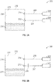
FIG. 2A is a schematic view of an embodiment of a purge system suitable for use with the aircraft ofFIGS. 1A and 1B ; -
FIG. 2B is a schematic view of an embodiment of a purge system suitable for use with the aircraft ofFIGS. 1A and 1B ; -
FIG. 2C is a schematic view of an embodiment of a purge system suitable for use with the aircraft ofFIGS. 1A and 1B ; and -
FIG. 2D is a schematic view of an embodiment of a purge system suitable for use with the aircraft ofFIGS. 1A and 1B . - Referring to the drawings,
FIG. 1A shows anaircraft 100. In the illustrated embodiment, theaircraft 100 include anaircraft body 102, anairflow source 104, andfuel tanks 110a-110c. In the illustrated embodiment, thefuel tanks 110a-110c utilize theairflow source 104 to transfer fuel vapors from within thefuel tanks 110a-110c to anoverboard location 108. Advantageously, by removing fuel vapors from within thefuel tanks 110a-110c potential ignition of fuel vapors is reduced without the use of complex or heavy inerting systems. In some embodiments, the above-referenced fuel tank system can be utilized on-board any suitable vehicle. The term "vehicle" includes any powered conveyance device, including but not limited to aircraft, marine vessels, railroad engines, or roadway motor vehicles. In some embodiments, the vehicle is an aircraft. In some embodiments, the vehicle is a marine vessel such as a marine vessel fueled by liquefied natural gas (LNG). In some embodiments, the above-referenced fuel tank system can be used for stationary applications, including but not limited to fuel depots, fuel storage, etc. - In the illustrated embodiment, the
airflow source 104 can provide an airflow to one or more of thefuel tanks 110a-110c. In the illustrated embodiment, theairflow source 104 is a duct that can receiveram air 106 during flight of the aircraft. The duct can be a NACA scoop to reduce drag during operation. Ramair 106 is airflow that is received by the aircraft due to movement of theaircraft 100. In other embodiments, theairflow source 104 can be other suitable source as described herein. In certain embodiments, theairflow source 104 can be an ambient airflow source, including, but not limited to ambient airflow from outside the aircraft (ram air), etc. In certain embodiments, ambient airflow can be directed within the aircraft body by a NACA scoop, etc. In certain embodiments, theairflow source 104 can be a ram air duct (as shown inFIG. 1A ) to utilize external airflow from outside the aircraft. In certain embodiments, theairflow source 104 can be a cabin airflow source to utilize airflow from within a passenger cabin of the aircraft. In certain embodiments, theairflow source 104 can be a cargo hold airflow source. In certain embodiments, theairflow source 104 can be a flight deck airflow source. Airflow sources from a cabin, cargo hold, and flight deck can be collectively referred to as fuselage sources. In certain embodiments, theairflow source 104 can be fan bleed air from an engine of the aircraft. In certain embodiments, theairflow source 104 is conditioned air from an environmental control system of the aircraft. In certain embodiments, theairflow source 104 can be a combination or hybrid of the airflow sources described herein. In certain embodiments, airflow sources can be selectively provided and combined to provide a desired airflow. In certain embodiments, theairflow source 104 can be augmented with a fan or other positive pressure device to provide airflow when sufficient airflow is not provided (ground operation). - In the illustrated embodiment, the
aircraft body 102 can includemultiple fuel tanks 110a-110c disposed throughout theaircraft body 102 to store fuel. In the illustrated embodiment, theaircraft 100 can include at least one of acenter tank 110a, andwing tanks fuel tanks 110a-110c is depleted forming a tank ullage that may contain fuel vapors and other hydrocarbons, as shown inFIGS. 2A-2C . - In the illustrated embodiment, each of the
fuel tanks 110a-110c includes at least oneinlet 112 and at least oneoutlet 114. In the illustrated embodiment,inlets 112 can introduce airflow from theairflow source 104 into the tank ullage of afuel tank 110a-110c. Introduced airflow along with fuel vapors and other hydrocarbons can be removed from the tank ullage of thefuel tank 110a-110c viaoutlets 114. In the illustrated embodiment, theoutlets 114 are in fluid communication with theoverboard air 108 to direct airflow and fuel vapors to theoverboard location 108. In the illustrated embodiment,inlets 112 frommultiple fuel tanks 110a-110c can be in fluid communication to share common lines. Similarly, in the illustrated embodiment,outlets 114 frommultiple fuel tanks 110a-110c can be in fluid communication to share common lines. - Referring to
FIG. 1B , another embodiment of theaircraft 100 is shown. In the illustrated embodiment, theaircraft 100 includes anejector 105. Theejector 105 passes theram air 106 that enters theairflow source 104 and is accelerated in a construction thereby producing a low pressure region to create suction. In the illustrated embodiment, the suction is applied to theoutlets 114 of thefuel tanks 110a-110c. In the illustrated embodiment, airflow is drawn through theinlets 112, through the tank ullage of thefuel tanks 110a-110c and out theoutlets 114 to an overboard location via the suction provided by theejector 105. - Referring to
FIG. 2A , afuel tank 210 of apurge system 200 suitable for use with theaircraft 100 is shown. Thepurge system 200 can further be referred to as a fuel tank safety system. In the illustrated embodiment, thepurge system 200 includes afuel tank 210 and anairflow source 204. In the illustrated embodiment, thepurge system 200 can introduce airflow within thefuel tank 210. Advantageously, thepurge system 200 can reduce fuel vapor temperatures and the presence of fuel vapors within thefuel tank 210 to reduce potential ignition of fuel vapors and other hydrocarbons. - In the illustrated embodiment, the
fuel tank 210 includes atank volume 211, at least oneinlet 212 and at least oneoutlet 214. Thefuel tank 210 can containliquid fuel 216. In the illustrated embodiment, the remaining volume within thetank volume 211 is thetank ullage 218. Thetank ullage 218 can contain fuel vapors and other hydrocarbons. Thetank ullage 218 can comprise various chemical compounds, including but not limited to components of air (e.g., nitrogen, oxygen) such as residual air from a tank filling process or outlet air that entered the tank to fill space previously occupied by liquid fuel as the fuel is consumed, water vapor, hydrocarbon vapor resulting from evaporation of liquid fuel. Advantageously, use of thepurge system 200 can reduce fuel vapor concentration within thetank ullage 218 below the lower explosive limit by removing fuel vapor and other hydrocarbons that could be ignited. - Further, the
purge system 200 can reduce the temperature of thetank ullage 218. Advantageously, the amount of fuel vapor within thetank ullage 218 is dependent on the temperature within thetank ullage 218. Therefore, below a threshold temperature, ignition of vapor within thetank ullage 218 will not occur. The threshold temperature can range from approximately 95 degrees F at sea level to approximately 55 degrees F at 40,000 feet. - In the illustrated embodiment, airflow can be introduced into the
tank ullage 218 via theinlets 212. Advantageously, the airflow can dilute and remove the fuel vapors within thetank ullage 218 while also reducingtank ullage 218 temperatures. In the illustrated embodiment, theinlets 212 are in fluid communication with anairflow source 204. Aninboard airflow 207 from theairflow source 204 to theinlets 212 is directed to thetank ullage 218. In certain embodiments, theinboard airflow 207 can be directed via a duct. - In the illustrated embodiment, the
airflow source 204 can provide airflow to thetank ullage 218 via theinlets 212. Theairflow source 204 provides low to no hydrocarbons to maintain thetank ullage 218 below flammability limits. In various embodiments, theairflow source 204 can be any suitable source of low to no hydrocarbon airflow. In certain embodiments, theairflow source 204 can be an ambient airflow source, including, but not limited to ambient airflow from outside the aircraft (ram air), etc. In certain embodiments, ambient airflow can be directed within the aircraft body by a NACA scoop, etc. In certain embodiments, theairflow source 204 can be a ram air duct (as shown inFIG. 1A as airflow source 104) to utilize external airflow from outside the aircraft. In certain embodiments, theairflow source 204 can be a cabin airflow source to utilize airflow from within a passenger cabin of the aircraft. In certain embodiments, theairflow source 204 can be a cargo hold airflow source. In certain embodiments, theairflow source 204 can be a flight deck airflow source. In certain embodiments, theairflow source 204 can be fan bleed air from an engine of the aircraft. In certain embodiments, theairflow source 204 is conditioned air from an environmental control system of the aircraft. In certain embodiments, theairflow source 204 can be a combination or hybrid of the airflow sources described herein. In certain embodiments, airflow sources can be selectively provided and combined to provide a desired airflow. - In the illustrated embodiment,
outlets 214 can direct airflow from thetank ullage 218 to anoverboard location 208 via anoutboard airflow 209. In the illustrated embodiment, airflow from theinlets 212 can dilute and mix with fuel vapors that are removed from thetank ullage 218 via theoutlets 214. In certain embodiments,outboard airflow 209 can be directed to a catalyst with a flame arrestor wherein theoutboard airflow 209 is burned to prevent hydrocarbon emissions. Any hydrocarbon vapors exiting the tank can be recaptured in any suitable manner. Advantageously, thepurge system 200 can keep thefuel ullage 218 below the lower explosive limits without the use of more complex methods that require additional components. - Referring to
FIG. 2B , another embodiment of thepurge system 200 is shown. In the illustrated embodiment, afan 205 is in fluid communication with theinbound airflow 207. Thefan 205 can provide positive pressure to theinbound airflow 207 to direct airflow into thetank ullage 218. Advantageously, thefan 205 can allow for airflow fromairflow sources 204 that may require external airflow, and can provide airflow when an aircraft is on the ground, or slowly moving, etc. - Referring to
FIG. 2C , another embodiment of thepurge system 200 is shown. In the illustrated embodiment, aregenerative heat exchanger 220 is in fluid communication with theinbound airflow 207. Theregenerative heat exchanger 220 includes apurge flow side 224 and anoverboard flow side 222. - In the illustrated embodiment,
inbound air flow 207 can pass through thepurge flow side 224 of theregenerative heat exchanger 220. In certain embodiments, theregenerative heat exchanger 220 can precondition theinbound air flow 207 to cool the air to lower the temperature within thetank ullage 218 to below lower explosive limits of the fuel vapor. In certain embodiments, theregenerative heat exchanger 220 can heat theinbound air flow 207 in order to raise the temperature of thefuel 216 to prevent icing or gelling. - In certain embodiments, the
regenerative heat exchanger 220 is in fluid communication with theoutbound airflow 209 via theoverboard flow side 222. In certain embodiments, heat can be transferred between theoutbound flow 209 and theinbound flow 207 as needed. - Referring to
FIG. 2D , another embodiment of thepurge system 200 is shown. In the illustrated embodiment, aconditioning device 230 is in fluid communication with theinbound airflow 207. Theconditioning device 230 can be an environmental control system, a vapor cycle machine, an air cycle machine, or any other suitable cooling or conditioning device. Theconditioning device 230 can provide cooling to theinbound airflow 207 by introducing cool air or by cooling the inbound airflow. Advantageously, cooled airflow can allow ullage gases to remain below the lower flammability limit. - In certain embodiments, a
drying device 232 is in fluid communication with theinbound airflow 207. Thedrying device 232 can be a drier or any other suitable device. Thedrying device 232 can further remove humidity from theinbound airflow 207. In certain embodiments,inbound airflow 207 can selectively bypass or partially bypass at least one of theconditioning device 230 and thedrying device 232 to provide a desired airflow. Advantageously, dried airflow can discourage bacterial growth and icing within thefuel tank 210. - The terminology used herein is for the purpose of describing particular embodiments only and is not intended to be limiting of the embodiments. While the description of the present embodiments has been presented for purposes of illustration and description, it is not intended to be exhaustive or limited to the embodiments in the form disclosed. Many modifications, variations, alterations, substitutions or equivalent arrangement not hereto described will be apparent to those of ordinary skill in the art without departing from the scope and spirit of the embodiments. Additionally, while various embodiments have been described, it is to be understood that aspects may include only some of the described embodiments. Accordingly, the embodiments are not to be seen as limited by the foregoing description, but are only limited by the scope of the appended claims.
Claims (15)
- A purge system (200), comprising:an airflow source (204) to provide an airflow; anda fuel tank (210), including:a tank volume including a tank ullage (218);at least one inlet (212), wherein the at least one inlet (212) is in fluid communication with the tank ullage (218) and the airflow source to provide the airflow as an inbound airflow to the tank ullage; andat least one outlet (214), wherein the at least one outlet (214) is in fluid communication with the tank ullage (218) and an overboard location outside the aircraft to direct the inbound airflow (207) as an outbound airflow (208) from the tank ullage (218) to the overboard location.
- The purge system of claim 1, wherein the airflow source (204) is an ambient air source, a fuselage source or an aircraft fan bleed air source.
- The purge system of claim 1 or 2, further comprising a conditioning device (230) in fluid communication with the inbound airflow (207).
- The purge system of any preceding claim, further comprising a drying device (232) in fluid communication with the inbound airflow (207).
- The purge system of any preceding claim, further comprising a fan (205) in fluid communication with the airflow.
- The purge system of any preceding claim, further comprising a heat exchanger (220) in fluid communication with the inbound airflow (207).
- The purge system of claim 6, wherein the heat exchanger (202) is in fluid communication with the outbound airflow (209) and the inbound airflow (207) is in thermal communication with the outbound airflow (209) via the heat exchanger (202).
- The purge system of any preceding claim, further comprising a suction device in fluid communication with the outbound airflow (209) to provide negative pressure to the outbound airflow (209).
- A method to purge hydrocarbon vapors, the method comprising:providing a cool airflow via an airflow source (204);providing a fuel tank (210) having a tank volume with a tank ullage (218);providing the cool airflow as an inbound airflow (207) to the tank ullage (218) via at least one purge duct of the fuel tank (210); anddirecting the inbound airflow (207) as an outbound airflow (209) from the tank ullage (218) to an overboard location via a vent of the fuel tank (210).
- The method of claim 9, wherein the cool airflow is cooled via a conditioning device (230).
- The method of claim 9 or 10, wherein the cool airflow is further dried via a drying device.
- The method of any of claims 9 to 11, wherein the airflow source is an ambient air source.
- The method of any of claims 9 to 12, wherein the airflow source is a fuselage air source.
- The method of any of claims 9 to 13, wherein the airflow source is an aircraft fan bleed air source.
- The method of any of claims 9 to 14, further comprising a fan in fluid communication with the airflow.
Applications Claiming Priority (1)
| Application Number | Priority Date | Filing Date | Title |
|---|---|---|---|
| US15/299,811 US10301034B2 (en) | 2016-10-21 | 2016-10-21 | Fuel tank ullage purge system |
Publications (2)
| Publication Number | Publication Date |
|---|---|
| EP3312092A1 true EP3312092A1 (en) | 2018-04-25 |
| EP3312092B1 EP3312092B1 (en) | 2020-01-08 |
Family
ID=60153153
Family Applications (1)
| Application Number | Title | Priority Date | Filing Date |
|---|---|---|---|
| EP17197441.3A Active EP3312092B1 (en) | 2016-10-21 | 2017-10-20 | Fuel tank ullage purge system |
Country Status (2)
| Country | Link |
|---|---|
| US (1) | US10301034B2 (en) |
| EP (1) | EP3312092B1 (en) |
Families Citing this family (1)
| Publication number | Priority date | Publication date | Assignee | Title |
|---|---|---|---|---|
| FR3137067A1 (en) * | 2022-06-24 | 2023-12-29 | Airbus | TANK SYSTEM WITH A VALVE IN THE FORM OF A PENDULUM SYSTEM |
Citations (5)
| Publication number | Priority date | Publication date | Assignee | Title |
|---|---|---|---|---|
| US2860815A (en) * | 1953-12-22 | 1958-11-18 | Exxon Research Engineering Co | Method of and apparatus for reducing water absorption by liquid fuels |
| US6343465B1 (en) * | 1999-06-25 | 2002-02-05 | Norman P. Martinov | Aircraft fuel tank explosion reduction safety method |
| US20080264951A1 (en) * | 2007-04-26 | 2008-10-30 | The Boeing Company | Sealing bladderless system and method |
| GB2477576A (en) * | 2010-02-09 | 2011-08-10 | Marshall Of Cambridge Aerospace Ltd | Leak prevention in aircraft fuel tanks |
| US20120035406A1 (en) * | 2010-08-03 | 2012-02-09 | Airbus Operations Limited | Dehydration of liquid fuel |
Family Cites Families (16)
| Publication number | Priority date | Publication date | Assignee | Title |
|---|---|---|---|---|
| US2944987A (en) | 1955-12-27 | 1960-07-12 | Stewart Warner Corp | Method and means for generating purge gases |
| GB1039361A (en) | 1964-04-08 | 1966-08-17 | Mini Of Aviat London | Means for preventing explosion in fuel tanks |
| US3672180A (en) | 1968-02-19 | 1972-06-27 | Edwin R Davis | Fuel vapor recovery apparatus |
| US3847298A (en) | 1972-03-20 | 1974-11-12 | Garrett Corp | Fuel tank inerting system |
| US4194924A (en) | 1978-12-13 | 1980-03-25 | The United States Of America As Represented By The Secretary Of The Air Force | Process for reclaiming aircraft fuel tank purging fluids |
| DE102008009274B4 (en) | 2008-02-15 | 2011-06-01 | Airbus Operations Gmbh | System and method for ventilating an area, in particular an explosive area of an aircraft |
| US8499567B2 (en) | 2011-06-27 | 2013-08-06 | Honeywell International, Inc. | Hybrid fuel tank inerting system |
| RU2487059C1 (en) | 2011-12-15 | 2013-07-10 | Открытое Акционерное Общество "Московский Вертолётный Завод Им. М.Л. Миля" | Aircraft fuel system |
| GB201204959D0 (en) * | 2012-03-21 | 2012-05-02 | Airbus Operations Ltd | Conditioning system for fuel cell exhaust |
| US8808428B2 (en) | 2012-03-27 | 2014-08-19 | The Boeing Company | Fuel vapor removal methods and systems for flammability reduction |
| US9114886B2 (en) * | 2012-03-27 | 2015-08-25 | The Boeing Company | Method and system for reducing the flammability of fuel-tanks onboard an aircraft |
| EP2740666B1 (en) | 2012-12-07 | 2017-03-22 | Airbus Operations GmbH | System and method for processing recirculation air |
| GB201303527D0 (en) * | 2013-02-28 | 2013-04-10 | Airbus Uk Ltd | Aircraft inerting system |
| US9447733B2 (en) | 2013-03-14 | 2016-09-20 | Pratt & Whitney Canada Corp. | Gas turbine engine fuel system with ecology valve |
| US10610712B2 (en) * | 2013-12-02 | 2020-04-07 | Aero Systems Consultants LLC | Aircraft fuel systems |
| US20160186671A1 (en) | 2014-12-24 | 2016-06-30 | General Electric Company | System and method for purging fuel from turbomachine |
-
2016
- 2016-10-21 US US15/299,811 patent/US10301034B2/en active Active
-
2017
- 2017-10-20 EP EP17197441.3A patent/EP3312092B1/en active Active
Patent Citations (5)
| Publication number | Priority date | Publication date | Assignee | Title |
|---|---|---|---|---|
| US2860815A (en) * | 1953-12-22 | 1958-11-18 | Exxon Research Engineering Co | Method of and apparatus for reducing water absorption by liquid fuels |
| US6343465B1 (en) * | 1999-06-25 | 2002-02-05 | Norman P. Martinov | Aircraft fuel tank explosion reduction safety method |
| US20080264951A1 (en) * | 2007-04-26 | 2008-10-30 | The Boeing Company | Sealing bladderless system and method |
| GB2477576A (en) * | 2010-02-09 | 2011-08-10 | Marshall Of Cambridge Aerospace Ltd | Leak prevention in aircraft fuel tanks |
| US20120035406A1 (en) * | 2010-08-03 | 2012-02-09 | Airbus Operations Limited | Dehydration of liquid fuel |
Also Published As
| Publication number | Publication date |
|---|---|
| US10301034B2 (en) | 2019-05-28 |
| US20180111696A1 (en) | 2018-04-26 |
| EP3312092B1 (en) | 2020-01-08 |
Similar Documents
| Publication | Publication Date | Title |
|---|---|---|
| US9114886B2 (en) | Method and system for reducing the flammability of fuel-tanks onboard an aircraft | |
| US11738874B2 (en) | Aircraft having hybrid-electric propulsion system with electric storage located in fuselage | |
| US7152635B2 (en) | Commercial aircraft on-board inerting system | |
| AU2012268924B2 (en) | Fuel vapor removal methods and systems for flammability reduction | |
| US10307708B2 (en) | Fuel tank system and method | |
| RU2706753C1 (en) | Catalytic inerting system for aircraft with several fuel tanks | |
| US9834314B2 (en) | Aircraft fuel tank inerting system | |
| US10654582B2 (en) | Fuel separation unit for inert gas generating system | |
| CN103768744A (en) | Thermodynamycally-optimized advanced fire suppression system | |
| EP3718898B1 (en) | Reuse of waste oxygen enriched air in an aircraft | |
| EP3312092B1 (en) | Fuel tank ullage purge system | |
| EP3418200B1 (en) | Catalytic oxidation product gas management | |
| GB2557302A (en) | An aircraft fuel tank | |
| WO2023215326A1 (en) | Modular hydrogen-fuel storage assembly | |
| EP3315412B1 (en) | Air separation system for fuel stabilization | |
| US12617546B2 (en) | Modular hydrogen-fuel storage assembly | |
| Westenberger | Hydrogen and fuel cells: mobile application in aviation |
Legal Events
| Date | Code | Title | Description |
|---|---|---|---|
| PUAI | Public reference made under article 153(3) epc to a published international application that has entered the european phase |
Free format text: ORIGINAL CODE: 0009012 |
|
| STAA | Information on the status of an ep patent application or granted ep patent |
Free format text: STATUS: THE APPLICATION HAS BEEN PUBLISHED |
|
| AK | Designated contracting states |
Kind code of ref document: A1 Designated state(s): AL AT BE BG CH CY CZ DE DK EE ES FI FR GB GR HR HU IE IS IT LI LT LU LV MC MK MT NL NO PL PT RO RS SE SI SK SM TR |
|
| AX | Request for extension of the european patent |
Extension state: BA ME |
|
| STAA | Information on the status of an ep patent application or granted ep patent |
Free format text: STATUS: REQUEST FOR EXAMINATION WAS MADE |
|
| 17P | Request for examination filed |
Effective date: 20181025 |
|
| RBV | Designated contracting states (corrected) |
Designated state(s): AL AT BE BG CH CY CZ DE DK EE ES FI FR GB GR HR HU IE IS IT LI LT LU LV MC MK MT NL NO PL PT RO RS SE SI SK SM TR |
|
| GRAP | Despatch of communication of intention to grant a patent |
Free format text: ORIGINAL CODE: EPIDOSNIGR1 |
|
| STAA | Information on the status of an ep patent application or granted ep patent |
Free format text: STATUS: GRANT OF PATENT IS INTENDED |
|
| INTG | Intention to grant announced |
Effective date: 20190305 |
|
| RAP1 | Party data changed (applicant data changed or rights of an application transferred) |
Owner name: HAMILTON SUNDSTRAND CORPORATION |
|
| GRAJ | Information related to disapproval of communication of intention to grant by the applicant or resumption of examination proceedings by the epo deleted |
Free format text: ORIGINAL CODE: EPIDOSDIGR1 |
|
| STAA | Information on the status of an ep patent application or granted ep patent |
Free format text: STATUS: REQUEST FOR EXAMINATION WAS MADE |
|
| GRAP | Despatch of communication of intention to grant a patent |
Free format text: ORIGINAL CODE: EPIDOSNIGR1 |
|
| STAA | Information on the status of an ep patent application or granted ep patent |
Free format text: STATUS: GRANT OF PATENT IS INTENDED |
|
| INTC | Intention to grant announced (deleted) | ||
| INTG | Intention to grant announced |
Effective date: 20190724 |
|
| GRAS | Grant fee paid |
Free format text: ORIGINAL CODE: EPIDOSNIGR3 |
|
| GRAA | (expected) grant |
Free format text: ORIGINAL CODE: 0009210 |
|
| STAA | Information on the status of an ep patent application or granted ep patent |
Free format text: STATUS: THE PATENT HAS BEEN GRANTED |
|
| AK | Designated contracting states |
Kind code of ref document: B1 Designated state(s): AL AT BE BG CH CY CZ DE DK EE ES FI FR GB GR HR HU IE IS IT LI LT LU LV MC MK MT NL NO PL PT RO RS SE SI SK SM TR |
|
| REG | Reference to a national code |
Ref country code: GB Ref legal event code: FG4D |
|
| REG | Reference to a national code |
Ref country code: CH Ref legal event code: EP |
|
| REG | Reference to a national code |
Ref country code: DE Ref legal event code: R096 Ref document number: 602017010607 Country of ref document: DE |
|
| REG | Reference to a national code |
Ref country code: IE Ref legal event code: FG4D |
|
| REG | Reference to a national code |
Ref country code: AT Ref legal event code: REF Ref document number: 1222395 Country of ref document: AT Kind code of ref document: T Effective date: 20200215 |
|
| REG | Reference to a national code |
Ref country code: NL Ref legal event code: MP Effective date: 20200108 |
|
| REG | Reference to a national code |
Ref country code: LT Ref legal event code: MG4D |
|
| PG25 | Lapsed in a contracting state [announced via postgrant information from national office to epo] |
Ref country code: NO Free format text: LAPSE BECAUSE OF FAILURE TO SUBMIT A TRANSLATION OF THE DESCRIPTION OR TO PAY THE FEE WITHIN THE PRESCRIBED TIME-LIMIT Effective date: 20200408 Ref country code: RS Free format text: LAPSE BECAUSE OF FAILURE TO SUBMIT A TRANSLATION OF THE DESCRIPTION OR TO PAY THE FEE WITHIN THE PRESCRIBED TIME-LIMIT Effective date: 20200108 Ref country code: FI Free format text: LAPSE BECAUSE OF FAILURE TO SUBMIT A TRANSLATION OF THE DESCRIPTION OR TO PAY THE FEE WITHIN THE PRESCRIBED TIME-LIMIT Effective date: 20200108 Ref country code: PT Free format text: LAPSE BECAUSE OF FAILURE TO SUBMIT A TRANSLATION OF THE DESCRIPTION OR TO PAY THE FEE WITHIN THE PRESCRIBED TIME-LIMIT Effective date: 20200531 Ref country code: NL Free format text: LAPSE BECAUSE OF FAILURE TO SUBMIT A TRANSLATION OF THE DESCRIPTION OR TO PAY THE FEE WITHIN THE PRESCRIBED TIME-LIMIT Effective date: 20200108 Ref country code: LT Free format text: LAPSE BECAUSE OF FAILURE TO SUBMIT A TRANSLATION OF THE DESCRIPTION OR TO PAY THE FEE WITHIN THE PRESCRIBED TIME-LIMIT Effective date: 20200108 |
|
| PG25 | Lapsed in a contracting state [announced via postgrant information from national office to epo] |
Ref country code: GR Free format text: LAPSE BECAUSE OF FAILURE TO SUBMIT A TRANSLATION OF THE DESCRIPTION OR TO PAY THE FEE WITHIN THE PRESCRIBED TIME-LIMIT Effective date: 20200409 Ref country code: HR Free format text: LAPSE BECAUSE OF FAILURE TO SUBMIT A TRANSLATION OF THE DESCRIPTION OR TO PAY THE FEE WITHIN THE PRESCRIBED TIME-LIMIT Effective date: 20200108 Ref country code: SE Free format text: LAPSE BECAUSE OF FAILURE TO SUBMIT A TRANSLATION OF THE DESCRIPTION OR TO PAY THE FEE WITHIN THE PRESCRIBED TIME-LIMIT Effective date: 20200108 Ref country code: LV Free format text: LAPSE BECAUSE OF FAILURE TO SUBMIT A TRANSLATION OF THE DESCRIPTION OR TO PAY THE FEE WITHIN THE PRESCRIBED TIME-LIMIT Effective date: 20200108 Ref country code: BG Free format text: LAPSE BECAUSE OF FAILURE TO SUBMIT A TRANSLATION OF THE DESCRIPTION OR TO PAY THE FEE WITHIN THE PRESCRIBED TIME-LIMIT Effective date: 20200408 Ref country code: IS Free format text: LAPSE BECAUSE OF FAILURE TO SUBMIT A TRANSLATION OF THE DESCRIPTION OR TO PAY THE FEE WITHIN THE PRESCRIBED TIME-LIMIT Effective date: 20200508 |
|
| REG | Reference to a national code |
Ref country code: DE Ref legal event code: R097 Ref document number: 602017010607 Country of ref document: DE |
|
| PG25 | Lapsed in a contracting state [announced via postgrant information from national office to epo] |
Ref country code: CZ Free format text: LAPSE BECAUSE OF FAILURE TO SUBMIT A TRANSLATION OF THE DESCRIPTION OR TO PAY THE FEE WITHIN THE PRESCRIBED TIME-LIMIT Effective date: 20200108 Ref country code: ES Free format text: LAPSE BECAUSE OF FAILURE TO SUBMIT A TRANSLATION OF THE DESCRIPTION OR TO PAY THE FEE WITHIN THE PRESCRIBED TIME-LIMIT Effective date: 20200108 Ref country code: SK Free format text: LAPSE BECAUSE OF FAILURE TO SUBMIT A TRANSLATION OF THE DESCRIPTION OR TO PAY THE FEE WITHIN THE PRESCRIBED TIME-LIMIT Effective date: 20200108 Ref country code: EE Free format text: LAPSE BECAUSE OF FAILURE TO SUBMIT A TRANSLATION OF THE DESCRIPTION OR TO PAY THE FEE WITHIN THE PRESCRIBED TIME-LIMIT Effective date: 20200108 Ref country code: SM Free format text: LAPSE BECAUSE OF FAILURE TO SUBMIT A TRANSLATION OF THE DESCRIPTION OR TO PAY THE FEE WITHIN THE PRESCRIBED TIME-LIMIT Effective date: 20200108 Ref country code: DK Free format text: LAPSE BECAUSE OF FAILURE TO SUBMIT A TRANSLATION OF THE DESCRIPTION OR TO PAY THE FEE WITHIN THE PRESCRIBED TIME-LIMIT Effective date: 20200108 Ref country code: RO Free format text: LAPSE BECAUSE OF FAILURE TO SUBMIT A TRANSLATION OF THE DESCRIPTION OR TO PAY THE FEE WITHIN THE PRESCRIBED TIME-LIMIT Effective date: 20200108 |
|
| PLBE | No opposition filed within time limit |
Free format text: ORIGINAL CODE: 0009261 |
|
| STAA | Information on the status of an ep patent application or granted ep patent |
Free format text: STATUS: NO OPPOSITION FILED WITHIN TIME LIMIT |
|
| REG | Reference to a national code |
Ref country code: AT Ref legal event code: MK05 Ref document number: 1222395 Country of ref document: AT Kind code of ref document: T Effective date: 20200108 |
|
| 26N | No opposition filed |
Effective date: 20201009 |
|
| PG25 | Lapsed in a contracting state [announced via postgrant information from national office to epo] |
Ref country code: AT Free format text: LAPSE BECAUSE OF FAILURE TO SUBMIT A TRANSLATION OF THE DESCRIPTION OR TO PAY THE FEE WITHIN THE PRESCRIBED TIME-LIMIT Effective date: 20200108 Ref country code: IT Free format text: LAPSE BECAUSE OF FAILURE TO SUBMIT A TRANSLATION OF THE DESCRIPTION OR TO PAY THE FEE WITHIN THE PRESCRIBED TIME-LIMIT Effective date: 20200108 |
|
| PG25 | Lapsed in a contracting state [announced via postgrant information from national office to epo] |
Ref country code: PL Free format text: LAPSE BECAUSE OF FAILURE TO SUBMIT A TRANSLATION OF THE DESCRIPTION OR TO PAY THE FEE WITHIN THE PRESCRIBED TIME-LIMIT Effective date: 20200108 Ref country code: SI Free format text: LAPSE BECAUSE OF FAILURE TO SUBMIT A TRANSLATION OF THE DESCRIPTION OR TO PAY THE FEE WITHIN THE PRESCRIBED TIME-LIMIT Effective date: 20200108 |
|
| REG | Reference to a national code |
Ref country code: CH Ref legal event code: PL |
|
| PG25 | Lapsed in a contracting state [announced via postgrant information from national office to epo] |
Ref country code: LU Free format text: LAPSE BECAUSE OF NON-PAYMENT OF DUE FEES Effective date: 20201020 Ref country code: MC Free format text: LAPSE BECAUSE OF FAILURE TO SUBMIT A TRANSLATION OF THE DESCRIPTION OR TO PAY THE FEE WITHIN THE PRESCRIBED TIME-LIMIT Effective date: 20200108 |
|
| REG | Reference to a national code |
Ref country code: BE Ref legal event code: MM Effective date: 20201031 |
|
| PG25 | Lapsed in a contracting state [announced via postgrant information from national office to epo] |
Ref country code: CH Free format text: LAPSE BECAUSE OF NON-PAYMENT OF DUE FEES Effective date: 20201031 Ref country code: BE Free format text: LAPSE BECAUSE OF NON-PAYMENT OF DUE FEES Effective date: 20201031 Ref country code: LI Free format text: LAPSE BECAUSE OF NON-PAYMENT OF DUE FEES Effective date: 20201031 |
|
| PG25 | Lapsed in a contracting state [announced via postgrant information from national office to epo] |
Ref country code: IE Free format text: LAPSE BECAUSE OF NON-PAYMENT OF DUE FEES Effective date: 20201020 |
|
| PG25 | Lapsed in a contracting state [announced via postgrant information from national office to epo] |
Ref country code: TR Free format text: LAPSE BECAUSE OF FAILURE TO SUBMIT A TRANSLATION OF THE DESCRIPTION OR TO PAY THE FEE WITHIN THE PRESCRIBED TIME-LIMIT Effective date: 20200108 Ref country code: MT Free format text: LAPSE BECAUSE OF FAILURE TO SUBMIT A TRANSLATION OF THE DESCRIPTION OR TO PAY THE FEE WITHIN THE PRESCRIBED TIME-LIMIT Effective date: 20200108 Ref country code: CY Free format text: LAPSE BECAUSE OF FAILURE TO SUBMIT A TRANSLATION OF THE DESCRIPTION OR TO PAY THE FEE WITHIN THE PRESCRIBED TIME-LIMIT Effective date: 20200108 |
|
| PG25 | Lapsed in a contracting state [announced via postgrant information from national office to epo] |
Ref country code: MK Free format text: LAPSE BECAUSE OF FAILURE TO SUBMIT A TRANSLATION OF THE DESCRIPTION OR TO PAY THE FEE WITHIN THE PRESCRIBED TIME-LIMIT Effective date: 20200108 Ref country code: AL Free format text: LAPSE BECAUSE OF FAILURE TO SUBMIT A TRANSLATION OF THE DESCRIPTION OR TO PAY THE FEE WITHIN THE PRESCRIBED TIME-LIMIT Effective date: 20200108 |
|
| P01 | Opt-out of the competence of the unified patent court (upc) registered |
Effective date: 20230522 |
|
| PGFP | Annual fee paid to national office [announced via postgrant information from national office to epo] |
Ref country code: GB Payment date: 20250923 Year of fee payment: 9 |
|
| PGFP | Annual fee paid to national office [announced via postgrant information from national office to epo] |
Ref country code: FR Payment date: 20250923 Year of fee payment: 9 |
|
| PGFP | Annual fee paid to national office [announced via postgrant information from national office to epo] |
Ref country code: DE Payment date: 20250923 Year of fee payment: 9 |