EP3312023A1 - Motorcycle tire - Google Patents
Motorcycle tire Download PDFInfo
- Publication number
- EP3312023A1 EP3312023A1 EP17186756.7A EP17186756A EP3312023A1 EP 3312023 A1 EP3312023 A1 EP 3312023A1 EP 17186756 A EP17186756 A EP 17186756A EP 3312023 A1 EP3312023 A1 EP 3312023A1
- Authority
- EP
- European Patent Office
- Prior art keywords
- tread
- reinforcing
- strip
- reinforcing layer
- cord
- Prior art date
- Legal status (The legal status is an assumption and is not a legal conclusion. Google has not performed a legal analysis and makes no representation as to the accuracy of the status listed.)
- Granted
Links
Images


Classifications
-
- B—PERFORMING OPERATIONS; TRANSPORTING
- B60—VEHICLES IN GENERAL
- B60C—VEHICLE TYRES; TYRE INFLATION; TYRE CHANGING; CONNECTING VALVES TO INFLATABLE ELASTIC BODIES IN GENERAL; DEVICES OR ARRANGEMENTS RELATED TO TYRES
- B60C9/00—Reinforcements or ply arrangement of pneumatic tyres
- B60C9/0042—Reinforcements made of synthetic materials
-
- B—PERFORMING OPERATIONS; TRANSPORTING
- B29—WORKING OF PLASTICS; WORKING OF SUBSTANCES IN A PLASTIC STATE IN GENERAL
- B29D—PRODUCING PARTICULAR ARTICLES FROM PLASTICS OR FROM SUBSTANCES IN A PLASTIC STATE
- B29D30/00—Producing pneumatic or solid tyres or parts thereof
- B29D30/06—Pneumatic tyres or parts thereof (e.g. produced by casting, moulding, compression moulding, injection moulding, centrifugal casting)
- B29D30/38—Textile inserts, e.g. cord or canvas layers, for tyres; Treatment of inserts prior to building the tyre
-
- B—PERFORMING OPERATIONS; TRANSPORTING
- B29—WORKING OF PLASTICS; WORKING OF SUBSTANCES IN A PLASTIC STATE IN GENERAL
- B29D—PRODUCING PARTICULAR ARTICLES FROM PLASTICS OR FROM SUBSTANCES IN A PLASTIC STATE
- B29D30/00—Producing pneumatic or solid tyres or parts thereof
- B29D30/06—Pneumatic tyres or parts thereof (e.g. produced by casting, moulding, compression moulding, injection moulding, centrifugal casting)
- B29D30/52—Unvulcanised treads, e.g. on used tyres; Retreading
- B29D30/58—Applying bands of rubber treads, i.e. applying camel backs
- B29D30/60—Applying bands of rubber treads, i.e. applying camel backs by winding narrow strips
-
- B—PERFORMING OPERATIONS; TRANSPORTING
- B60—VEHICLES IN GENERAL
- B60C—VEHICLE TYRES; TYRE INFLATION; TYRE CHANGING; CONNECTING VALVES TO INFLATABLE ELASTIC BODIES IN GENERAL; DEVICES OR ARRANGEMENTS RELATED TO TYRES
- B60C9/00—Reinforcements or ply arrangement of pneumatic tyres
- B60C9/02—Carcasses
- B60C9/04—Carcasses the reinforcing cords of each carcass ply arranged in a substantially parallel relationship
- B60C9/08—Carcasses the reinforcing cords of each carcass ply arranged in a substantially parallel relationship the cords extend transversely from bead to bead, i.e. radial ply
-
- B—PERFORMING OPERATIONS; TRANSPORTING
- B60—VEHICLES IN GENERAL
- B60C—VEHICLE TYRES; TYRE INFLATION; TYRE CHANGING; CONNECTING VALVES TO INFLATABLE ELASTIC BODIES IN GENERAL; DEVICES OR ARRANGEMENTS RELATED TO TYRES
- B60C9/00—Reinforcements or ply arrangement of pneumatic tyres
- B60C9/18—Structure or arrangement of belts or breakers, crown-reinforcing or cushioning layers
- B60C9/20—Structure or arrangement of belts or breakers, crown-reinforcing or cushioning layers built-up from rubberised plies each having all cords arranged substantially parallel
-
- B—PERFORMING OPERATIONS; TRANSPORTING
- B60—VEHICLES IN GENERAL
- B60C—VEHICLE TYRES; TYRE INFLATION; TYRE CHANGING; CONNECTING VALVES TO INFLATABLE ELASTIC BODIES IN GENERAL; DEVICES OR ARRANGEMENTS RELATED TO TYRES
- B60C9/00—Reinforcements or ply arrangement of pneumatic tyres
- B60C9/18—Structure or arrangement of belts or breakers, crown-reinforcing or cushioning layers
- B60C9/20—Structure or arrangement of belts or breakers, crown-reinforcing or cushioning layers built-up from rubberised plies each having all cords arranged substantially parallel
- B60C9/22—Structure or arrangement of belts or breakers, crown-reinforcing or cushioning layers built-up from rubberised plies each having all cords arranged substantially parallel the plies being arranged with all cords disposed along the circumference of the tyre
-
- B—PERFORMING OPERATIONS; TRANSPORTING
- B60—VEHICLES IN GENERAL
- B60C—VEHICLE TYRES; TYRE INFLATION; TYRE CHANGING; CONNECTING VALVES TO INFLATABLE ELASTIC BODIES IN GENERAL; DEVICES OR ARRANGEMENTS RELATED TO TYRES
- B60C9/00—Reinforcements or ply arrangement of pneumatic tyres
- B60C9/18—Structure or arrangement of belts or breakers, crown-reinforcing or cushioning layers
- B60C9/20—Structure or arrangement of belts or breakers, crown-reinforcing or cushioning layers built-up from rubberised plies each having all cords arranged substantially parallel
- B60C9/22—Structure or arrangement of belts or breakers, crown-reinforcing or cushioning layers built-up from rubberised plies each having all cords arranged substantially parallel the plies being arranged with all cords disposed along the circumference of the tyre
- B60C9/2204—Structure or arrangement of belts or breakers, crown-reinforcing or cushioning layers built-up from rubberised plies each having all cords arranged substantially parallel the plies being arranged with all cords disposed along the circumference of the tyre obtained by circumferentially narrow strip winding
-
- B—PERFORMING OPERATIONS; TRANSPORTING
- B29—WORKING OF PLASTICS; WORKING OF SUBSTANCES IN A PLASTIC STATE IN GENERAL
- B29B—PREPARATION OR PRETREATMENT OF THE MATERIAL TO BE SHAPED; MAKING GRANULES OR PREFORMS; RECOVERY OF PLASTICS OR OTHER CONSTITUENTS OF WASTE MATERIAL CONTAINING PLASTICS
- B29B15/00—Pretreatment of the material to be shaped, not covered by groups B29B7/00 - B29B13/00
- B29B15/08—Pretreatment of the material to be shaped, not covered by groups B29B7/00 - B29B13/00 of reinforcements or fillers
-
- B—PERFORMING OPERATIONS; TRANSPORTING
- B29—WORKING OF PLASTICS; WORKING OF SUBSTANCES IN A PLASTIC STATE IN GENERAL
- B29D—PRODUCING PARTICULAR ARTICLES FROM PLASTICS OR FROM SUBSTANCES IN A PLASTIC STATE
- B29D30/00—Producing pneumatic or solid tyres or parts thereof
- B29D30/06—Pneumatic tyres or parts thereof (e.g. produced by casting, moulding, compression moulding, injection moulding, centrifugal casting)
- B29D30/38—Textile inserts, e.g. cord or canvas layers, for tyres; Treatment of inserts prior to building the tyre
- B29D2030/383—Chemical treatment of the reinforcing elements, e.g. cords, wires and filamentary materials, to increase the adhesion to the rubber
-
- B—PERFORMING OPERATIONS; TRANSPORTING
- B60—VEHICLES IN GENERAL
- B60C—VEHICLE TYRES; TYRE INFLATION; TYRE CHANGING; CONNECTING VALVES TO INFLATABLE ELASTIC BODIES IN GENERAL; DEVICES OR ARRANGEMENTS RELATED TO TYRES
- B60C11/00—Tyre tread bands; Tread patterns; Anti-skid inserts
-
- B—PERFORMING OPERATIONS; TRANSPORTING
- B60—VEHICLES IN GENERAL
- B60C—VEHICLE TYRES; TYRE INFLATION; TYRE CHANGING; CONNECTING VALVES TO INFLATABLE ELASTIC BODIES IN GENERAL; DEVICES OR ARRANGEMENTS RELATED TO TYRES
- B60C9/00—Reinforcements or ply arrangement of pneumatic tyres
- B60C9/18—Structure or arrangement of belts or breakers, crown-reinforcing or cushioning layers
- B60C9/20—Structure or arrangement of belts or breakers, crown-reinforcing or cushioning layers built-up from rubberised plies each having all cords arranged substantially parallel
- B60C9/22—Structure or arrangement of belts or breakers, crown-reinforcing or cushioning layers built-up from rubberised plies each having all cords arranged substantially parallel the plies being arranged with all cords disposed along the circumference of the tyre
- B60C2009/2223—Structure or arrangement of belts or breakers, crown-reinforcing or cushioning layers built-up from rubberised plies each having all cords arranged substantially parallel the plies being arranged with all cords disposed along the circumference of the tyre with an interrupted zero degree ply, e.g. using two or more portions for the same ply
-
- B—PERFORMING OPERATIONS; TRANSPORTING
- B60—VEHICLES IN GENERAL
- B60C—VEHICLE TYRES; TYRE INFLATION; TYRE CHANGING; CONNECTING VALVES TO INFLATABLE ELASTIC BODIES IN GENERAL; DEVICES OR ARRANGEMENTS RELATED TO TYRES
- B60C9/00—Reinforcements or ply arrangement of pneumatic tyres
- B60C9/18—Structure or arrangement of belts or breakers, crown-reinforcing or cushioning layers
- B60C9/20—Structure or arrangement of belts or breakers, crown-reinforcing or cushioning layers built-up from rubberised plies each having all cords arranged substantially parallel
- B60C9/22—Structure or arrangement of belts or breakers, crown-reinforcing or cushioning layers built-up from rubberised plies each having all cords arranged substantially parallel the plies being arranged with all cords disposed along the circumference of the tyre
- B60C2009/2252—Physical properties or dimension of the zero degree ply cords
-
- B—PERFORMING OPERATIONS; TRANSPORTING
- B60—VEHICLES IN GENERAL
- B60C—VEHICLE TYRES; TYRE INFLATION; TYRE CHANGING; CONNECTING VALVES TO INFLATABLE ELASTIC BODIES IN GENERAL; DEVICES OR ARRANGEMENTS RELATED TO TYRES
- B60C9/00—Reinforcements or ply arrangement of pneumatic tyres
- B60C9/18—Structure or arrangement of belts or breakers, crown-reinforcing or cushioning layers
- B60C9/20—Structure or arrangement of belts or breakers, crown-reinforcing or cushioning layers built-up from rubberised plies each having all cords arranged substantially parallel
- B60C9/22—Structure or arrangement of belts or breakers, crown-reinforcing or cushioning layers built-up from rubberised plies each having all cords arranged substantially parallel the plies being arranged with all cords disposed along the circumference of the tyre
- B60C2009/2252—Physical properties or dimension of the zero degree ply cords
- B60C2009/2266—Density of the cords in width direction
- B60C2009/2271—Density of the cords in width direction with variable density
-
- B—PERFORMING OPERATIONS; TRANSPORTING
- B60—VEHICLES IN GENERAL
- B60C—VEHICLE TYRES; TYRE INFLATION; TYRE CHANGING; CONNECTING VALVES TO INFLATABLE ELASTIC BODIES IN GENERAL; DEVICES OR ARRANGEMENTS RELATED TO TYRES
- B60C9/00—Reinforcements or ply arrangement of pneumatic tyres
- B60C9/18—Structure or arrangement of belts or breakers, crown-reinforcing or cushioning layers
- B60C9/20—Structure or arrangement of belts or breakers, crown-reinforcing or cushioning layers built-up from rubberised plies each having all cords arranged substantially parallel
- B60C9/22—Structure or arrangement of belts or breakers, crown-reinforcing or cushioning layers built-up from rubberised plies each having all cords arranged substantially parallel the plies being arranged with all cords disposed along the circumference of the tyre
- B60C2009/2252—Physical properties or dimension of the zero degree ply cords
- B60C2009/2295—Physical properties or dimension of the zero degree ply cords with different cords in the same layer
-
- B—PERFORMING OPERATIONS; TRANSPORTING
- B60—VEHICLES IN GENERAL
- B60C—VEHICLE TYRES; TYRE INFLATION; TYRE CHANGING; CONNECTING VALVES TO INFLATABLE ELASTIC BODIES IN GENERAL; DEVICES OR ARRANGEMENTS RELATED TO TYRES
- B60C2200/00—Tyres specially adapted for particular applications
- B60C2200/10—Tyres specially adapted for particular applications for motorcycles, scooters or the like
-
- B—PERFORMING OPERATIONS; TRANSPORTING
- B60—VEHICLES IN GENERAL
- B60C—VEHICLE TYRES; TYRE INFLATION; TYRE CHANGING; CONNECTING VALVES TO INFLATABLE ELASTIC BODIES IN GENERAL; DEVICES OR ARRANGEMENTS RELATED TO TYRES
- B60C2200/00—Tyres specially adapted for particular applications
- B60C2200/12—Tyres specially adapted for particular applications for bicycles
Definitions
- the present invention relates to a motorcycle tire, more particularly to a structure of a tread reinforcing layer capable of improving the handling stability and riding comfort in a well-balanced manner.
- the carcass is tightly hooped and increased in the apparent rigidity over the entire width of the tread portion so that the tire is improved in the handling stability.
- the apparent rigidity of the carcass is increased, vibrations during running are not fully absorbed, and riding comfort is not good.
- Patent Document 1 Japanese Patent Application Publication No.JPH09-118109
- the present invention was made, and a primary object thereof is to provide a motorcycle tire in which, by improving a tread reinforcing layer, the handling stability and riding comfort can be improved in a well-balanced manner.
- a motorcycle tire comprises a tread portion, a pair of sidewall portions, a pair of bead portions, a carcass extending between the bead portions through the tread portion and the sidewall portions, and a tread reinforcing layer disposed radially outside the carcass in the tread portion, wherein the tread reinforcing layer is composed of a helically wound strip of parallel reinforcing cords coated with topping rubber, and the winding pitch of the wound strip is larger in a central part and axially outer shoulder parts of the tread reinforcing layer than in middle parts of the tread reinforcing layer between the central part and the shoulder parts.
- motorcycle tire according to the present invention may include the following features (1)-(6):
- the normally inflated unloaded condition is such that the tire is mounted on a standard wheel rim and inflate to a standard pressure but loaded with no tire load.
- the standard wheel rim is a wheel rim officially approved or recommended for the tire by standards organizations, i.e. JATMA (Japan and Asia), T&RA (North America), ETRTO (Europe), TRAA (Australia), STRO (Scandinavia), ALAPA (Latin America), ITTAC (India) and the like which are effective in the area where the tire is manufactured, sold or used.
- the standard pressure and the standard tire load are the maximum air pressure and the maximum tire load for the tire specified by the same organization in the Air-pressure/Maximum-load Table or similar list.
- the standard wheel rim is the "standard rim” specified in JATMA, the "Measuring Rim” in ETRTO, the "Design Rim” in TRA or the like.
- the standard pressure is the "maximum air pressure" in JATMA, the "Inflation Pressure” in ETRTO, the maximum pressure given in the "Tire Load Limits at various Cold Inflation Pressures” table in TRA or the like.
- Fig. 1 shows a motorcycle tire 1 as an embodiment of the present invention under the normally inflated unloaded condition.
- the motorcycle tire 1 is a pneumatic tire comprising a tread portion 2 whose outer surface defines the tread face 2a, a pair of axially spaced bead portions 4, a pair of sidewall portions 3 extending between the tread edges 2t and the bead portions 4, a carcass 6 extending between the bead portions 4 through the tread portion 2 and the sidewall portions 3, and a tread reinforcing layer 7 disposed radially outside the carcass 6 in the tread portion 2.
- the tread portion 2 (inclusive of the carcass 6, tread reinforcement layer 7 and a tread rubber thereon) is curved with a relatively small radius of curvature when compared with the passenger car tires, truck/bus tires and the like, and the maximum cross section width of the tire lies between the tread edges 2t.
- the undermentioned developed tread width TWe is a length measured between the tread edges 2t along the tread face 2a in a tire meridian section.
- tread portion 2 can be provided with grooves for the purpose of drainage although not shown in the drawings.
- the carcass 6 is composed of at least one ply 6A (in the present embodiment, a single ply 6A) of cords extending between the bead portions 4 through the tread portion 2 and the sidewall portions 3, and turned up around a bead core 5 in each of the bead portions so as to form a pair of turnup portions 6b and a main portion 6a therebetween.
- Each of the bead portions 4 is provided between the main portion 6a and turnup portion 6b with a bead apex rubber 8 made of hard rubber.
- the tread reinforcing layer 7 comprises one ply of circumferentially and helically wound reinforcing cords 11.
- the tread reinforcing layer 7 is made up of a single ply of circumferentially and helically wound reinforcing cords 11, therefore, the tread reinforcing layer 7 is the so-called zero-degree band 9 consisting a single ply 9A.
- the axial ends 7e of the tread reinforcing layer 7 are positioned in the vicinities of the tread edges 2t.
- the tread reinforcing layer 7 in combination with a belt or breaker formed of reinforcing cords inclined relatively largely with respect to the tire circumferential direction.
- the breaker may be of cross breaker plies.
- the breaker may be disposed radially inside or outside the tread reinforcing layer 7.
- the tread reinforcing layer 7 in combination with another tread reinforcing layer 7, in other words, the tread reinforcing layer 7 may comprise two plies of circumferentially and helically wound reinforcing cords 11.
- the tread reinforcing layer 7 is, as shown in Fig. 2 , formed by circumferentially and helically winding a strip 10 of the reinforcing cords 11 which are laid along the length of the strip in parallel with each other and coated with topping rubber 12.
- Such tread reinforcing layer 7 suppress movements of the tread portion 2 during running, and helps to improve the handling stability.
- the winding pitch Pm of the strip 10 in the middle parts Mi is smaller than the winding pitch Pc of the strip 10 in the central part Cr, and smaller than the winding pitch Ps of the strip 10 in the shoulder parts Sh as shown in Fig. 3 . Accordingly, the rigidity is increased in the middle parts Mi on which large load is exerted when the motorcycle is leaned to initiate cornering or end the cornering, therefore, large traction can be secured and the handling stability is improved.
- the rigidity is decreased in the central part Cr and the shoulder parts Sh, therefore, the vibrations caused during straight running can be effectively absorbed, and the riding comfort is improved. Furthermore, as the rigidity is decreased in the shoulder parts Sh, the contact of the tread portion with the ground is increased during cornering, and the handling stability can be improved.
- the winding pitch Pc of the strip 10 in the central part Cr is greater than the winding pitch Ps of the strip 10 in the shoulder parts Sh.
- the rigidity of the shoulder parts Sh becomes higher than the rigidity of the central part Cr.
- the winding pitches P suitable for the respective parts Cr, Mi and Sh are adopted. Thereby, a traction suitable for the leaning of the motorcycle can be generated, and the vibrations caused during the running can be effectively absorbed. Thus, the handling stability and the riding comfort can be improved in a good balance.
- a ratio P/La of the winding pitch P of the strip 10 to a distance La between the outermost points 11a and 11b of the respective outermost reinforcing cords 11e and 11i in the strip 10 in the widthwise direction of the strip as shown in Fig. 2 (referred to as the pitch ratio P/La) is preferably set as follows:
- the distance La between the outermost reinforcing cords 11e and 11i in the strip 10 is preferably set in a range from 2 to 8.2 mm. If the distance La is more than 8.2 mm, the difference between the winding diameters of the axially innermost and outermost reinforcing cords 11 in the strip 10 is increased, and the reinforcing cords 11 in the strip 10 may have excessively large differences in the cord tension. If the distance La is less than 2 mm, the number of winding the strip 10 is increased, and there is a possibility that the productivity of forming the tread reinforcing layer 7 is deteriorated.
- the number of the reinforcing cords 11 in the strip 10 is set in a range from 2 to 7.
- the arrangement pitch of the cords is constant.
- the number of the reinforcing cords 11 is 8 or more, the difference between the winding diameters of the axially innermost and outermost reinforcing cords 11 in the strip 10 is increased, and there is a possibility that the rigidity distribution of the strip 10 is pulsatively varied in the widthwise direction thereof or in the tire axial direction. If the number of the reinforcing cords 11 is 1, it may take a long time to form the tread reinforcing layer 7.
- each of the reinforcing cords 11 has an initial elongation percentage (a) in a range from 0.2% to 1.0%.
- the initial elongation percentage is a difference between an elongation at a load of 2.5N and an elongation at a load of 49N of the cord, more specifically, an elongation of the cord in terms of a percentage when a load applied to the cord is increased from 2.5N to 49N.
- the initial elongation percentage (a) is less than 0.2%, the absorption of vibrations caused during running is likely to reduce, and the riding comfort is deteriorated. If the initial elongation percentage (a) exceeds 1.0%, the rigidity of the tread reinforcing layer 7 becomes excessively low, therefore, there is a possibility that the traction is decreased and the handling stability is deteriorated.
- reinforcing cords 11 for example, steel cords, aramid fiber cords and the like can be suitably used.
- the tread reinforcing layer 7 is made up of a first halved reinforcing layer 7A disposed on one side (left side in Fig. 1 ) of the tire equator C and formed by winding a first strip 10A, and a second halved reinforcing layer 7B disposed on the other side (right side in Fig. 1 ) of the tire equator C and formed by winding a second strip 10B.
- the strip 10 includes the first strip 10A and the second strip 10B.
- each of the strips 10A and 10B comprises three reinforcing cords 11: a first reinforcing cord 11A, a second reinforcing cord 11B and a third reinforcing cord 11C.
- the first reinforcing cord 11A is axially innermost
- the second reinforcing cord 11B is axially outermost
- the third reinforcing cord 11C is disposed therebetween.
- the initial elongation percentage a2 of the axially outside second reinforcing cord 11B is greater than the initial elongation percentage a1 of the axially inside first reinforcing cord 11A.
- the tread portion 2 of the motorcycle tire 1 has a profile curved convexly toward the radially outside, therefore, in the strip 10, the winding diameter of the axially outside second reinforcing cord 11B becomes smaller than the winding diameter of the axially inside first reinforcing cord 11A.
- the tread reinforcing layer 7 can provide necessary rigidity by the axially inside first reinforcing cords 11A.
- the tread reinforcing layer 7 is provided with flexibility which enables to absorb vibrations during running. Therefore, it is possible to improve the handling stability and riding comfort in a well-balanced manner.
- the initial elongation percentage a1 of the axially inside first reinforcing cord 11A is in a range from 50% to 90% of the initial elongation percentage a2 of the axially outside second reinforcing cord 11B.
- the initial elongation percentage of the in-between reinforcing cord may be the same as that of either the first reinforcing cord 11A or the second reinforcing cord 11B. But, it is preferable that the initial elongation percentages (a) of the reinforcing cords 11 in the strip 10 are gradually decreased from the axially outermost reinforcing cord 11B to the axially innermost reinforcing cord 11A.
- the difference (a3-a1) in the initial elongation percentage between the third reinforcing cord 11C and the axially inside first reinforcing cord 11A is smaller than the difference (a2-a3) in the initial elongation percentage between the axially outside second reinforcing cord 11B and the third reinforcing cord 11C because the inclination angle with respect to the tire axial direction, of the profile of the tread reinforcing layer 7 becomes larger toward the tread edge 2t than the tire equator C due to the curvature, therefore, the difference in the winding diameter between the axially outside second reinforcing cord 11B and the third reinforcing cord 11C is larger than the difference in the winding diameter between the third reinforcing cord 11C and the axially inside first reinforcing cords 11A.
- the developed width Wa of the tread reinforcing layer 7 is preferably not less than 75%, more preferably not less than 80% of the developed tread width TWe in order that the tread reinforcing layer 7 effectively exerts its hooping effect to the carcass 6 in order to improve the handling stability.
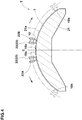
- Fig. 4 shows an example of a method for manufacturing the tread reinforcing layer 7 of the tire 1 in the present embodiment.
- a manufacturing apparatus T is used.
- the manufacturing apparatus T comprises a drum 21 and applicators 22 as schematic shown in Fig. 4 .
- the outer peripheral surface of the drum 21 is provided with a profiled shaping surface 21a on which the strips 10 are wound.
- the profiled shaping surface 21a is convexly curved according to the profile of the tread reinforcing layer 7 to be formed.
- the applicators 22 feed the strips 10 with the shaping surface 21a of the drum 21.
- the drum 21 has a spindle rotatably supported by a main frame (not shown) equipped with a drive unit for rotating the drum 21.
- the applicator 22 in this example is a belt conveyer provided at the downstream end with a feed roller 23.
- a rubber extruder (not shown) for extruding the strip 10 is provided so that the strip 10 is continuously supplied to the applicator 22.
- the applicator 22 is movably supported by a moving device (not shown) so that the applicator 22 in particular the feed roller 23 can move in the axial direction and radially direction of the drum 21.
- the feed roller 23 traverse the shaping surface 21a, while rotating the drum so that the strip 10 is wound helically and circumferentially on the drum 21.
- the applicators 22 are a first applicator 22A for the first halved reinforcing layer 7A and a second applicator 22B for the second halved reinforcing layer 7B.
- the process for forming the tread reinforcing layer 7 in the present embodiment is as follows:
- the applicators 22A and 22B are set on both sides of the center plane of the drum 21 corresponding to the tire equator C and near the center plane. More specifically, the first applicator 22A for forming the first halved reinforcing layer 7A is set on one side (left side in Fig. 4 ) of the center plane (C). The second applicator 22B for forming the second halved reinforcing layer 7B is set on the other side (right side in Fig. 4 ) of the center plane (C).
- the feed rollers 23 of the applicators 22A and 22B may be set at different positions in the circumferential direction of the drum, and/or the winding start time of the applicator 22A and the winding start time of the applicator 22B may be delayed one from the other.
- the start ends 10a of the first and second strips 10A and 10B fed by the applicators 22A and 22B are pressed against and adhered to the shaping surface 21a at positions adjacent to and on both sides of the center plane (C), for example, by the use of pressure rollers (not shown).
- the axially inside first reinforcing cord 11A in the first strip 10A and the axially inside first reinforcing cord 11A in the second strip 10B are positioned adjacently to each other in the axial direction on both sides of the center plane (C).
- the applicators 22A and 22B are moved toward the respective axial outer sides.
- a controller (not shown) controls the traversing speed of each applicator, the feed rate of each strip 10 and the rotational speed of the drum 21 to achieve the above-mentioned winding pitches Pc, Pm and Ps in the respective parts Cr, Mi and Sh.
- the tread reinforcing layer 7 consisting of the first halved reinforcing layer 7A and the second halved reinforcing layer 7B is formed.
- test tire inflated to 290 kPa
- rear wheel size 18 X MT6.00
- the test rider evaluated the handling stability based on handle response and cornering characteristics regarding traction and grip, as well as the riding comfort based on absorption of vibrations.
- the results are indicated in Table 1 by an index based on Conventional example (Conv) being 100, wherein the larger value is better.
- an identical tire of size 120/70R17 having a conventional structure was used as the front tire.
Landscapes
- Engineering & Computer Science (AREA)
- Mechanical Engineering (AREA)
- Textile Engineering (AREA)
- Tires In General (AREA)
Abstract
Description
- The present invention relates to a motorcycle tire, more particularly to a structure of a tread reinforcing layer capable of improving the handling stability and riding comfort in a well-balanced manner.
- There has been known a motorcycle tire provided in the tread portion with a tread reinforcing layer formed by helically winding a rubber strip in which parallel reinforcing cords are embedded. The strip is wound such that the sides of axially adjacent turns of the strip abut on each other.
- By providing such tread reinforcing layer, the carcass is tightly hooped and increased in the apparent rigidity over the entire width of the tread portion so that the tire is improved in the handling stability.
However, as the apparent rigidity of the carcass is increased, vibrations during running are not fully absorbed, and riding comfort is not good. - Patent Document 1: Japanese Patent Application Publication No.JPH09-118109
- In view of the circumstances described above, the present invention was made, and a primary object thereof is to provide a motorcycle tire in which, by improving a tread reinforcing layer, the handling stability and riding comfort can be improved in a well-balanced manner.
- According to the present invention, a motorcycle tire comprises
a tread portion,
a pair of sidewall portions,
a pair of bead portions,
a carcass extending between the bead portions through the tread portion and the sidewall portions, and
a tread reinforcing layer disposed radially outside the carcass in the tread portion, wherein
the tread reinforcing layer is composed of a helically wound strip of parallel reinforcing cords coated with topping rubber, and
the winding pitch of the wound strip is larger in a central part and axially outer shoulder parts of the tread reinforcing layer than in middle parts of the tread reinforcing layer between the central part and the shoulder parts. - Further, the motorcycle tire according to the present invention may include the following features (1)-(6):
- (1) the winding pitch is larger in the central part than in the axially outer shoulder parts;
- (2) a pitch ratio P/La of the winding pitch P of the strip to a distance La between the reinforcing cords in the strip which are closest to the respective two sides of the strip is 162% to 260% in the central part, 129% to 162% in the middle parts, and 140% to 240% in the shoulder parts;
- (3) the width of the central part measured along the tread face is 10% to 52% of a tread reinforcing layer width which is the width of the tread reinforcing layer measure along the tread face,
the width of each of the middle parts measured along the tread face is 17% to 38% of the tread reinforcing layer width, and
the width of each of the shoulder parts measured along the tread face is 7% to 28% of the tread reinforcing layer width; - (4) the tread reinforcing layer is composed of a first halved reinforcing layer disposed on one side of the tire equator, and a second halved reinforcing layer disposed on the other side of the tire equator,
the strip includes a first strip to form the first halved reinforcing layer, and a second strip to form the second halved reinforcing layer,
the reinforcing cords of the first strip include an axially inside first reinforcing cord and an axially outside second reinforcing cord disposed axially outside the first reinforcing cord,
the reinforcing cords of the second strip include an axially inside first reinforcing cord and an axially outside second reinforcing cord disposed axially outside the first reinforcing cord, and
in each of the first strip and the second strip, an initial elongation percentage a2 of the axially outside second reinforcing cord is greater than an initial elongation percentage a1 of the axially inside first reinforcing cord, wherein the initial elongation percentage of a reinforcing cord is an elongation of the cord in terms of a percentage when a load applied to the cord is increased from 2.5N to 49N; - (5) the initial elongation percentage a1 of the axially inside first reinforcing cord is in a range from 50% to 90% of the initial elongation percentage a2 of the axially outside second reinforcing cord;
- (6) the distance La between the reinforcing cords in the strip is in a range from 2.0 to 8.2 mm.
- In this application including specification and claims, various dimensions, positions and the like of the tire refer to those under a normally inflated unloaded condition of the tire unless otherwise noted.
- The normally inflated unloaded condition is such that the tire is mounted on a standard wheel rim and inflate to a standard pressure but loaded with no tire load.
- The standard wheel rim is a wheel rim officially approved or recommended for the tire by standards organizations, i.e. JATMA (Japan and Asia), T&RA (North America), ETRTO (Europe), TRAA (Australia), STRO (Scandinavia), ALAPA (Latin America), ITTAC (India) and the like which are effective in the area where the tire is manufactured, sold or used.
The standard pressure and the standard tire load are the maximum air pressure and the maximum tire load for the tire specified by the same organization in the Air-pressure/Maximum-load Table or similar list.
For example, the standard wheel rim is the "standard rim" specified in JATMA, the "Measuring Rim" in ETRTO, the "Design Rim" in TRA or the like. The standard pressure is the "maximum air pressure" in JATMA, the "Inflation Pressure" in ETRTO, the maximum pressure given in the "Tire Load Limits at various Cold Inflation Pressures" table in TRA or the like. -
-
Fig. 1 is a cross-sectional view of a motorcycle tire as an embodiment of the present invention. -
Fig. 2 is a schematic perspective partial view of an example of the strip of parallel reinforcing cords coated with topping rubber which is helically wound into the tread reinforcing layer. -
Fig. 3 is a cross sectional view of the left-hand part of the tread portion of the motorcycle tire shown inFig. 1 . -
Fig. 4 is a schematic cross-sectional view for explaining a method for manufacturing the tread reinforcing layer in the present embodiment. - Embodiments of the present invention will now be described in conjunction with accompanying drawings. The present invention can be applied to a pneumatic motorcycle tire regardless of for front wheel or rear wheel.
-
Fig. 1 shows a motorcycle tire 1 as an embodiment of the present invention under the normally inflated unloaded condition. - As shown, the motorcycle tire 1 is a pneumatic tire comprising a
tread portion 2 whose outer surface defines thetread face 2a, a pair of axially spacedbead portions 4, a pair ofsidewall portions 3 extending between thetread edges 2t and thebead portions 4, acarcass 6 extending between thebead portions 4 through thetread portion 2 and thesidewall portions 3, and atread reinforcing layer 7 disposed radially outside thecarcass 6 in thetread portion 2. - As a characteristic of a motorcycle tire, the tread portion 2 (inclusive of the
carcass 6,tread reinforcement layer 7 and a tread rubber thereon) is curved with a relatively small radius of curvature when compared with the passenger car tires, truck/bus tires and the like, and the maximum cross section width of the tire lies between thetread edges 2t. - The undermentioned developed tread width TWe is a length measured between the
tread edges 2t along thetread face 2a in a tire meridian section. - Incidentally, the
tread portion 2 can be provided with grooves for the purpose of drainage although not shown in the drawings. - The
carcass 6 is composed of at least oneply 6A (in the present embodiment, asingle ply 6A) of cords extending between thebead portions 4 through thetread portion 2 and thesidewall portions 3, and turned up around abead core 5 in each of the bead portions so as to form a pair ofturnup portions 6b and amain portion 6a therebetween. - Each of the
bead portions 4 is provided between themain portion 6a andturnup portion 6b with abead apex rubber 8 made of hard rubber. - The
tread reinforcing layer 7 comprises one ply of circumferentially and helically wound reinforcingcords 11. In the present embodiment, thetread reinforcing layer 7 is made up of a single ply of circumferentially and helically wound reinforcingcords 11, therefore, thetread reinforcing layer 7 is the so-called zero-degree band 9 consisting asingle ply 9A. Theaxial ends 7e of thetread reinforcing layer 7 are positioned in the vicinities of thetread edges 2t. - Incidentally, it may be possible to use the
tread reinforcing layer 7 in combination with a belt or breaker formed of reinforcing cords inclined relatively largely with respect to the tire circumferential direction. In such case, the breaker may be of cross breaker plies. In such case, the breaker may be disposed radially inside or outside thetread reinforcing layer 7. Further, it may be possible to use thetread reinforcing layer 7 in combination with anothertread reinforcing layer 7, in other words, thetread reinforcing layer 7 may comprise two plies of circumferentially and helically wound reinforcingcords 11. - The
tread reinforcing layer 7 is, as shown inFig. 2 , formed by circumferentially and helically winding astrip 10 of the reinforcingcords 11 which are laid along the length of the strip in parallel with each other and coated with toppingrubber 12. Suchtread reinforcing layer 7 suppress movements of thetread portion 2 during running, and helps to improve the handling stability. - As shown in
Fig. 1 , when thetread reinforcing layer 7 is sectioned into a central part Cr centered on the tire equator C, a pair of axially outermost shoulder parts Sh, and a pair of middle parts Mi therebetween,
the winding pitch Pm of thestrip 10 in the middle parts Mi is smaller than the winding pitch Pc of thestrip 10 in the central part Cr, and smaller than the winding pitch Ps of thestrip 10 in the shoulder parts Sh as shown inFig. 3 .
Accordingly, the rigidity is increased in the middle parts Mi on which large load is exerted when the motorcycle is leaned to initiate cornering or end the cornering, therefore, large traction can be secured and the handling stability is improved. Further, in comparison with the middle parts Mi, the rigidity is decreased in the central part Cr and the shoulder parts Sh, therefore, the vibrations caused during straight running can be effectively absorbed, and the riding comfort is improved. Furthermore, as the rigidity is decreased in the shoulder parts Sh, the contact of the tread portion with the ground is increased during cornering, and the handling stability can be improved. - Preferably, the winding pitch Pc of the
strip 10 in the central part Cr is greater than the winding pitch Ps of thestrip 10 in the shoulder parts Sh. Thereby, the rigidity of the shoulder parts Sh becomes higher than the rigidity of the central part Cr. Thus, when the shoulder part Sh is subjected to a larger load in the axial direction, namely, during cornering, larger traction can be ensured. Therefore, more excellent handling stability is exhibited, while improving the riding comfort during straight running. - As described, in the present embodiment, depending on the magnitude of load acting on the respective parts Cr, Mi and Sh, the winding pitches P suitable for the respective parts Cr, Mi and Sh are adopted. Thereby, a traction suitable for the leaning of the motorcycle can be generated, and the vibrations caused during the running can be effectively absorbed. Thus, the handling stability and the riding comfort can be improved in a good balance.
- In order to effectively derive the effects described above, a ratio P/La of the winding pitch P of the
strip 10 to a distance La between theoutermost points cords strip 10 in the widthwise direction of the strip as shown inFig. 2 , (referred to as the pitch ratio P/La) is preferably set as follows: - the pitch ratio Pc/La of the winding pitch Pc in the central part Cr is preferably 162% to 260%;
- the pitch ratio Pm/La of the winding pitch Pm in the middle parts Mi is preferably 129% to 162%; and
- the pitch ratio Ps/La of the winding pitch Ps in the shoulder parts Sh is preferably 140% to 240%.
- The distance La between the outermost reinforcing
cords strip 10 is preferably set in a range from 2 to 8.2 mm. If the distance La is more than 8.2 mm, the difference between the winding diameters of the axially innermost and outermost reinforcingcords 11 in thestrip 10 is increased, and the reinforcingcords 11 in thestrip 10 may have excessively large differences in the cord tension. If the distance La is less than 2 mm, the number of winding thestrip 10 is increased, and there is a possibility that the productivity of forming thetread reinforcing layer 7 is deteriorated. - Preferably, the number of the reinforcing
cords 11 in thestrip 10 is set in a range from 2 to 7. - when the number of the reinforcing
cords 11 in thestrip 10 is 3 or more, it is preferable that the arrangement pitch of the cords is constant. - If the number of the reinforcing
cords 11 is 8 or more, the difference between the winding diameters of the axially innermost and outermost reinforcingcords 11 in thestrip 10 is increased, and there is a possibility that the rigidity distribution of thestrip 10 is pulsatively varied in the widthwise direction thereof or in the tire axial direction. If the number of the reinforcingcords 11 is 1, it may take a long time to form thetread reinforcing layer 7. - Preferably, each of the reinforcing
cords 11 has an initial elongation percentage (a) in a range from 0.2% to 1.0%. - Here, the initial elongation percentage is a difference between an elongation at a load of 2.5N and an elongation at a load of 49N of the cord, more specifically, an elongation of the cord in terms of a percentage when a load applied to the cord is increased from 2.5N to 49N.
- If the initial elongation percentage (a) is less than 0.2%, the absorption of vibrations caused during running is likely to reduce, and the riding comfort is deteriorated. If the initial elongation percentage (a) exceeds 1.0%, the rigidity of the
tread reinforcing layer 7 becomes excessively low, therefore, there is a possibility that the traction is decreased and the handling stability is deteriorated. - As to the reinforcing
cords 11, for example, steel cords, aramid fiber cords and the like can be suitably used. - In the present embodiment, the
tread reinforcing layer 7 is made up of
a first halved reinforcinglayer 7A disposed on one side (left side inFig. 1 ) of the tire equator C and formed by winding afirst strip 10A, and
a second halved reinforcinglayer 7B disposed on the other side (right side inFig. 1 ) of the tire equator C and formed by winding asecond strip 10B.
Thus, thestrip 10 includes thefirst strip 10A and thesecond strip 10B. - In the present embodiment, as shown in
Fig. 3 , each of thestrips cord 11A, a second reinforcingcord 11B and a third reinforcingcord 11C.
In thetread reinforcing layer 7, the first reinforcingcord 11A is axially innermost, the second reinforcingcord 11B is axially outermost and the third reinforcingcord 11C is disposed therebetween. - It is preferable that the initial elongation percentage a2 of the axially outside second reinforcing
cord 11B is greater than the initial elongation percentage a1 of the axially inside first reinforcingcord 11A.
Thetread portion 2 of the motorcycle tire 1 has a profile curved convexly toward the radially outside, therefore, in thestrip 10, the winding diameter of the axially outside second reinforcingcord 11B becomes smaller than the winding diameter of the axially inside first reinforcingcord 11A.
By setting the initial elongation percentage a2 of the axially outside second reinforcingcord 11B to be greater than the initial elongation percentage a1 of the axially inside first reinforcingcord 11A, the tension of the axially inside first reinforcingcord 11A is increased more than the tension of the axially outside second reinforcingcord 11B.
Thus, thetread reinforcing layer 7 can provide necessary rigidity by the axially inside first reinforcingcords 11A. At the same time, by the axially outside second reinforcingcords 11A arranged alternately with the axially inside first reinforcingcords 11A, thetread reinforcing layer 7 is provided with flexibility which enables to absorb vibrations during running. Therefore, it is possible to improve the handling stability and riding comfort in a well-balanced manner. - In order to effectively derive the effects described above, it is preferred that the initial elongation percentage a1 of the axially inside first reinforcing
cord 11A is in a range from 50% to 90% of the initial elongation percentage a2 of the axially outside second reinforcingcord 11B. - If the
strip 10 include at least one reinforcing cord between the axially inside first reinforcingcord 11A and the axially outside second reinforcingcord 11B as in this example, the initial elongation percentage of the in-between reinforcing cord may be the same as that of either the first reinforcingcord 11A or the second reinforcingcord 11B.
But, it is preferable that the initial elongation percentages (a) of the reinforcingcords 11 in thestrip 10 are gradually decreased from the axially outermost reinforcingcord 11B to the axially innermost reinforcingcord 11A. - Furthermore, it is preferred that the difference (a3-a1) in the initial elongation percentage between the third reinforcing
cord 11C and the axially inside first reinforcingcord 11A is smaller than the difference (a2-a3) in the initial elongation percentage between the axially outside second reinforcingcord 11B and the third reinforcingcord 11C because the inclination angle with respect to the tire axial direction, of the profile of thetread reinforcing layer 7 becomes larger toward thetread edge 2t than the tire equator C due to the curvature, therefore,
the difference in the winding diameter between the axially outside second reinforcingcord 11B and the third reinforcingcord 11C is larger than the difference in the winding diameter between the third reinforcingcord 11C and the axially inside first reinforcingcords 11A. - The developed width Wa of the
tread reinforcing layer 7 is preferably not less than 75%, more preferably not less than 80% of the developed tread width TWe in order that thetread reinforcing layer 7 effectively exerts its hooping effect to thecarcass 6 in order to improve the handling stability. -
Fig. 4 shows an example of a method for manufacturing thetread reinforcing layer 7 of the tire 1 in the present embodiment. In this example, a manufacturing apparatus T is used. - The manufacturing apparatus T comprises a
drum 21 andapplicators 22 as schematic shown inFig. 4 .
The outer peripheral surface of thedrum 21 is provided with a profiledshaping surface 21a on which thestrips 10 are wound. The profiledshaping surface 21a is convexly curved according to the profile of thetread reinforcing layer 7 to be formed. - The
applicators 22 feed thestrips 10 with the shapingsurface 21a of thedrum 21. - The
drum 21 has a spindle rotatably supported by a main frame (not shown) equipped with a drive unit for rotating thedrum 21. - The
applicator 22 in this example is a belt conveyer provided at the downstream end with afeed roller 23.
On the upstream side of theapplicator 22, a rubber extruder (not shown) for extruding thestrip 10 is provided so that thestrip 10 is continuously supplied to theapplicator 22.
Theapplicator 22 is movably supported by a moving device (not shown) so that theapplicator 22 in particular thefeed roller 23 can move in the axial direction and radially direction of thedrum 21.
Thus, thefeed roller 23 traverse theshaping surface 21a, while rotating the drum so that thestrip 10 is wound helically and circumferentially on thedrum 21.
In this example, theapplicators 22 are afirst applicator 22A for the first halved reinforcinglayer 7A and asecond applicator 22B for the second halved reinforcinglayer 7B. - The process for forming the
tread reinforcing layer 7 in the present embodiment is as follows: - First, the
applicators drum 21 corresponding to the tire equator C and near the center plane.
More specifically, thefirst applicator 22A for forming the first halved reinforcinglayer 7A is set on one side (left side inFig. 4 ) of the center plane (C). Thesecond applicator 22B for forming the second halved reinforcinglayer 7B is set on the other side (right side inFig. 4 ) of the center plane (C).
At this time, in order that thefeed rollers 23 of theapplicators feed rollers 23 may be set at different positions in the circumferential direction of the drum, and/or
the winding start time of theapplicator 22A and the winding start time of theapplicator 22B may be delayed one from the other. - Next, the start ends 10a of the first and
second strips applicators surface 21a at positions adjacent to and on both sides of the center plane (C), for example, by the use of pressure rollers (not shown).
At this time, the axially inside first reinforcingcord 11A in thefirst strip 10A and the axially inside first reinforcingcord 11A in thesecond strip 10B are positioned adjacently to each other in the axial direction on both sides of the center plane (C). - Then, while rotating the
drum 21, theapplicators
At this time, a controller (not shown) controls the traversing speed of each applicator, the feed rate of eachstrip 10 and the rotational speed of thedrum 21 to achieve the above-mentioned winding pitches Pc, Pm and Ps in the respective parts Cr, Mi and Sh. - when the first and
second strips strips tread reinforcing layer 7. Thus, thetread reinforcing layer 7 consisting of the first halved reinforcinglayer 7A and the second halved reinforcinglayer 7B is formed. - while detailed description has been made of a preferable embodiment of the present invention, the present invention can be embodied in various forms without being limited to the illustrated embodiment.
- Motorcycle tires of size 190/50ZR17 having the specifications shown in Table 1 were manufactured as test tires, and tested for the handling stability and riding comfort.
The test tires were working examples (Ex.1-Ex.29) and Comparative examples (Ref.1-Ref.3) manufactured based on the structure shown inFig. 1 , and Conventional example (Conv). - Common specifications are as follows:
- Developed width Wa of Tread reinforcing layer Wa/Developed tread width TWe: 84%
- Number of Reinforcing cords in Each strip: 3
- Reinforcing cords: steel cords
- Distance La between Reinforcing cords: 3.3 mm
- Initial elongation percentage of First reinforcing cord: 0.8%
- Each test tire (inflated to 290 kPa) was mounted on the rear wheel (size 18 X MT6.00) of a 1300cc motorcycle, and was run on a dry asphalt road of a test course.
During running, the test rider evaluated the handling stability based on handle response and cornering characteristics regarding traction and grip, as well as the riding comfort based on absorption of vibrations.
The results are indicated in Table 1 by an index based on Conventional example (Conv) being 100, wherein the larger value is better.
For all the test tires (rear tires), an identical tire of size 120/70R17 having a conventional structure was used as the front tire.Table 1 Tire Conv Ref.1 Ref.2 Ref.3 Ex.1 Ex.2 Ex.3 Ex.4 Ex.5 Ex.6 Pc/La(%) 129 160 190 120 190 150 170 260 280 190 Pm/La(%) 129 180 140 140 140 140 140 140 140 110 Ps/La(%) 129 155 120 175 175 145 165 175 175 175 Wc/Wa(%) -- 15 15 15 15 15 15 15 15 15 Wm/Wa(%) -- 32.5 32.5 32.5 32.5 32.5 32.5 32.5 32.5 32.5 Ws/Wa(%) -- 10 10 10 10 10 10 10 10 10 a1/a2(%) 100 75 75 75 75 75 75 75 75 75 handling stability 100 100 103 101 110 112 110 110 107 110 riding comfort 100 103 102 102 110 106 110 110 111 108 Tire Ex.7 Ex.8 Ex.9 Ex.10 Ex.11 Ex.12 Ex.13 Ex.14 Ex.15 Ex.16 Pc/La(%) 190 190 190 190 190 250 260 190 190 190 Pm/La(%) 130 160 170 120 130 140 140 140 140 140 Ps/La(%) 175 175 175 130 140 240 250 175 175 175 Wc/Wa(%) 15 15 15 15 15 15 15 10 15 35 Wm/Wa(%) 32.5 32.5 32.5 32.5 32.5 32.5 32.5 38 35 25 Ws/Wa(%) 10 10 10 10 10 10 10 7 7.5 7.5 a1/a2(%) 75 75 75 75 75 75 75 75 75 75 handling stability 110 110 107 113 110 110 106 112 110 107 riding comfort 110 110 111 105 110 110 112 105 110 111 Tire Ex.17 Ex.22 Ex.23 Ex.24 Ex.25 Ex.26 Ex.27 Ex.28 Ex.29 Pc/La(%) 190 190 190 190 190 190 190 190 190 Pm/La(%) 140 140 140 140 140 140 140 140 140 Ps/La(%) 175 175 175 175 175 175 175 175 175 Wc/Wa(%) 52 10 10 20 10 15 15 15 15 Wm/Wa(%) 17 38 35 25 17 32.5 32.5 32.5 32.5 Ws/Wa(%) 7 7 10 15 28 10 10 10 10 a1/a2(%) 75 75 75 75 75 45 50 90 100 handling stability 103 110 110 108 106 108 110 110 109 riding comfort 113 110 110 111 112 107 110 110 106 - From the test results, it was confirmed that working example tires were improved in the riding comfort and handling stability in a good balance in comparison with Comparative example tires.
-
- 1
- motorcycle tire
- 2
- tread portion
- 3
- sidewall portion
- 4
- bead portion
- 5
- bead core
- 6
- carcass
- 7
- tread reinforcing layer
- 10
- strip
- 11
- reinforcing cord
- 12
- topping rubber
- Cr
- central part
- Mi
- middle part
- Sh
- shoulder part
the width Wm of each of the middle parts Mi measured along the
Claims (7)
- A motorcycle tire comprising:a tread portion having a tread face,a pair of sidewall portions,a pair of bead portions,a carcass extending between the bead portions through the tread portion and the sidewall portions, anda tread reinforcing layer disposed radially outside the carcass in the tread portion,
whereinthe tread reinforcing layer is composed of a helically wound strip of parallel reinforcing cords coated with topping rubber, andthe winding pitch of the wound strip is larger in a central part and axially outer shoulder parts of the tread reinforcing layer than in middle parts of the tread reinforcing layer between the central part and the shoulder parts. - The motorcycle tire according to claim 1, wherein
the winding pitch is larger in the central part than in the axially outer shoulder parts. - The motorcycle tire according to claim 1 or 2, wherein
a pitch ratio P/La of the winding pitch P of the strip to a distance La between the reinforcing cords in the strip which are closest to respective two sides of the strip is
162% to 260% in the central part,
129% to 162% in the middle parts, and
140% to 240% in the shoulder parts. - The motorcycle tire according to claim 1, 2 or 3, wherein
a width of the central part measured along the tread face is 10% to 52% of a tread reinforcing layer width which is a width of the tread reinforcing layer measure along the tread face,
a width of each of the middle parts measured along the tread face is 17% to 38% of the tread reinforcing layer width, and
a width of each of the shoulder parts measured along the tread face is 7% to 28% of the tread reinforcing layer width. - The motorcycle tire according claim 1, 2, 3 or 4, wherein
the tread reinforcing layer is composed of a first halved reinforcing layer disposed on one side of the tire equator, and a second halved reinforcing layer disposed on the other side of the tire equator,
the strip includes a first strip to form the first halved reinforcing layer, and a second strip to form the second halved reinforcing layer,
the reinforcing cords of the first strip include an axially inside first reinforcing cord and an axially outside second reinforcing cord disposed axially outside the axially inside first reinforcing cord,
the reinforcing cords of the second strip include an axially inside first reinforcing cord and an axially outside second reinforcing cord disposed axially outside the axially inside first reinforcing cord, and
in each of the first strip and the second strip, an initial elongation percentage a2 of the axially outside second reinforcing cord is greater than an initial elongation percentage a1 of the axially inside first reinforcing cord, wherein
the initial elongation percentage of a reinforcing cord is an elongation of the cord in terms of a percentage when a load applied to the cord is increased from 2.5N to 49N. - The motorcycle tire according to claim 5, wherein
the initial elongation percentage a1 of the axially inside first reinforcing cord is in a range from 50% to 90% of the initial elongation percentage a2 of the axially outside second reinforcing cord. - The motorcycle tire according to claim 3, wherein
the distance La between the reinforcing cords in the strip is in a range from 2.0 to 8.2 mm.
Applications Claiming Priority (1)
| Application Number | Priority Date | Filing Date | Title |
|---|---|---|---|
| JP2016168178 | 2016-08-30 |
Publications (2)
| Publication Number | Publication Date |
|---|---|
| EP3312023A1 true EP3312023A1 (en) | 2018-04-25 |
| EP3312023B1 EP3312023B1 (en) | 2019-10-09 |
Family
ID=59655940
Family Applications (1)
| Application Number | Title | Priority Date | Filing Date |
|---|---|---|---|
| EP17186756.7A Active EP3312023B1 (en) | 2016-08-30 | 2017-08-18 | Motorcycle tire |
Country Status (4)
| Country | Link |
|---|---|
| US (1) | US10654319B2 (en) |
| EP (1) | EP3312023B1 (en) |
| JP (1) | JP6907820B2 (en) |
| CN (1) | CN107791750B (en) |
Cited By (1)
| Publication number | Priority date | Publication date | Assignee | Title |
|---|---|---|---|---|
| CN111251786A (en) * | 2020-03-17 | 2020-06-09 | 中策橡胶集团有限公司 | Motorcycle or electric vehicle tyre with 0-degree variable winding density belt ply |
Families Citing this family (6)
| Publication number | Priority date | Publication date | Assignee | Title |
|---|---|---|---|---|
| JP6911496B2 (en) * | 2017-05-01 | 2021-07-28 | 住友ゴム工業株式会社 | Motorcycle tires |
| JP7119868B2 (en) * | 2018-10-03 | 2022-08-17 | 住友ゴム工業株式会社 | tire |
| JP7268434B2 (en) * | 2019-03-22 | 2023-05-08 | 住友ゴム工業株式会社 | motorcycle tire |
| JP7467964B2 (en) * | 2019-03-22 | 2024-04-16 | 住友ゴム工業株式会社 | Motorcycle tires |
| JP2020203613A (en) | 2019-06-18 | 2020-12-24 | 株式会社ブリヂストン | tire |
| JP7302391B2 (en) * | 2019-09-03 | 2023-07-04 | 住友ゴム工業株式会社 | motorcycle tire |
Citations (4)
| Publication number | Priority date | Publication date | Assignee | Title |
|---|---|---|---|---|
| JPH09118109A (en) | 1995-08-01 | 1997-05-06 | Pirelli Coordinamento Pneumatici Spa | Tire for two-wheel barrow |
| JP2007326498A (en) * | 2006-06-08 | 2007-12-20 | Sumitomo Rubber Ind Ltd | Pneumatic tires for motorcycles |
| JP2009113604A (en) * | 2007-11-05 | 2009-05-28 | Bridgestone Corp | Pneumatic tire for motorcycle |
| US20110308678A1 (en) * | 2008-12-17 | 2011-12-22 | Francis Bordoz | Vehicle Tire Comprising a Tread Composed of a Plurality of Compounds and a Layer of Circumferential Reinforcement Elements of Variable Pitch |
Family Cites Families (13)
| Publication number | Priority date | Publication date | Assignee | Title |
|---|---|---|---|---|
| IT1204980B (en) * | 1987-04-28 | 1989-03-10 | Pirelli | TIRES REINFORCEMENT REINFORCEMENT FOR VEHICLE WHEELS |
| US6425426B1 (en) * | 1999-12-07 | 2002-07-30 | Michelin Recherche Et Technique S.A. | Pneumatic tire with cords directly contacting tread compound |
| JP2002001833A (en) * | 2000-06-26 | 2002-01-08 | Sumitomo Rubber Ind Ltd | Method of forming band of pneumatic tire |
| GB2404636B (en) * | 2003-08-01 | 2006-12-20 | Dunlop Tyres Ltd | Motorcycle radial tyre |
| JP2007084025A (en) * | 2005-09-26 | 2007-04-05 | Bridgestone Corp | Pneumatic tire for two-wheeler |
| EP2017093B1 (en) * | 2007-07-20 | 2010-12-15 | Sumitomo Rubber Industries, Ltd. | Pneumatic tire |
| FR2939721B1 (en) * | 2008-12-17 | 2010-12-31 | Michelin Soc Tech | PNEUMATIC FOR CARCASS VEHICLES INTERRUPTED AND COMPRISING A LAYER OF CIRCUMFERENTIAL REINFORCING ELEMENTS |
| FR2939723B1 (en) * | 2008-12-17 | 2010-12-31 | Michelin Soc Tech | PNEUMATIC VEHICLE COMPRISING A LAYER OF CIRCUMFERENTIAL REINFORCING ELEMENTS |
| BRPI0823305B8 (en) * | 2008-12-22 | 2020-03-31 | Pirelli | tire for two-wheel vehicles, and, process for making a tire. |
| JP6003024B2 (en) * | 2011-08-24 | 2016-10-05 | 横浜ゴム株式会社 | Pneumatic radial tire for passenger cars |
| JP5412503B2 (en) * | 2011-12-26 | 2014-02-12 | 住友ゴム工業株式会社 | Motorcycle tires |
| JP5918742B2 (en) * | 2013-12-03 | 2016-05-18 | 住友ゴム工業株式会社 | Manufacturing method of pneumatic tire for motorcycle |
| CN106163780B (en) * | 2014-04-22 | 2019-01-01 | 住友橡胶工业株式会社 | The manufacturing method of pneumatic tire and pneumatic tire |
-
2017
- 2017-08-18 EP EP17186756.7A patent/EP3312023B1/en active Active
- 2017-08-28 US US15/688,223 patent/US10654319B2/en active Active
- 2017-08-29 JP JP2017164737A patent/JP6907820B2/en active Active
- 2017-08-29 CN CN201710755346.6A patent/CN107791750B/en active Active
Patent Citations (4)
| Publication number | Priority date | Publication date | Assignee | Title |
|---|---|---|---|---|
| JPH09118109A (en) | 1995-08-01 | 1997-05-06 | Pirelli Coordinamento Pneumatici Spa | Tire for two-wheel barrow |
| JP2007326498A (en) * | 2006-06-08 | 2007-12-20 | Sumitomo Rubber Ind Ltd | Pneumatic tires for motorcycles |
| JP2009113604A (en) * | 2007-11-05 | 2009-05-28 | Bridgestone Corp | Pneumatic tire for motorcycle |
| US20110308678A1 (en) * | 2008-12-17 | 2011-12-22 | Francis Bordoz | Vehicle Tire Comprising a Tread Composed of a Plurality of Compounds and a Layer of Circumferential Reinforcement Elements of Variable Pitch |
Cited By (1)
| Publication number | Priority date | Publication date | Assignee | Title |
|---|---|---|---|---|
| CN111251786A (en) * | 2020-03-17 | 2020-06-09 | 中策橡胶集团有限公司 | Motorcycle or electric vehicle tyre with 0-degree variable winding density belt ply |
Also Published As
| Publication number | Publication date |
|---|---|
| JP6907820B2 (en) | 2021-07-21 |
| JP2018034787A (en) | 2018-03-08 |
| US10654319B2 (en) | 2020-05-19 |
| US20180056721A1 (en) | 2018-03-01 |
| CN107791750A (en) | 2018-03-13 |
| CN107791750B (en) | 2021-02-02 |
| EP3312023B1 (en) | 2019-10-09 |
Similar Documents
| Publication | Publication Date | Title |
|---|---|---|
| EP3312023B1 (en) | Motorcycle tire | |
| US9713943B2 (en) | Pneumatic tire | |
| EP2497656B1 (en) | Pneumatic tire | |
| EP2607104B1 (en) | Pneumatic tire | |
| EP2743099B1 (en) | Motorcycle tire | |
| EP2962874B1 (en) | Pneumatic radial tire for passenger vehicle | |
| CN101888934A (en) | Pneumatic tire | |
| EP3960497B1 (en) | Tire | |
| CN103874590B (en) | pneumatic tire | |
| EP2979900B1 (en) | Heavy load pneumatic tire | |
| EP3213929B1 (en) | Pneumatic tire for passenger cars | |
| WO2020066906A1 (en) | Pneumatic tire | |
| EP1057659B1 (en) | Pneumatic radial tire for passenger car | |
| EP2602125A1 (en) | Pneumatic tire | |
| EP3251875A1 (en) | Pneumatic tire for motorcycle | |
| US11772425B2 (en) | Pneumatic tire | |
| EP3521059B1 (en) | Motorcycle tire | |
| EP3521060B1 (en) | Motorcycle tire | |
| EP3533623B1 (en) | Tire | |
| JP7758952B2 (en) | tire | |
| EP4574459A1 (en) | Tire | |
| EP3539796B1 (en) | Tire | |
| EP3539797B1 (en) | Tire | |
| JP2022045556A (en) | Tire, manufacturing method for tire, and tire design method |
Legal Events
| Date | Code | Title | Description |
|---|---|---|---|
| PUAI | Public reference made under article 153(3) epc to a published international application that has entered the european phase |
Free format text: ORIGINAL CODE: 0009012 |
|
| STAA | Information on the status of an ep patent application or granted ep patent |
Free format text: STATUS: THE APPLICATION HAS BEEN PUBLISHED |
|
| AK | Designated contracting states |
Kind code of ref document: A1 Designated state(s): AL AT BE BG CH CY CZ DE DK EE ES FI FR GB GR HR HU IE IS IT LI LT LU LV MC MK MT NL NO PL PT RO RS SE SI SK SM TR |
|
| AX | Request for extension of the european patent |
Extension state: BA ME |
|
| STAA | Information on the status of an ep patent application or granted ep patent |
Free format text: STATUS: REQUEST FOR EXAMINATION WAS MADE |
|
| 17P | Request for examination filed |
Effective date: 20181010 |
|
| RBV | Designated contracting states (corrected) |
Designated state(s): AL AT BE BG CH CY CZ DE DK EE ES FI FR GB GR HR HU IE IS IT LI LT LU LV MC MK MT NL NO PL PT RO RS SE SI SK SM TR |
|
| RIC1 | Information provided on ipc code assigned before grant |
Ipc: B60C 9/22 20060101AFI20181108BHEP Ipc: B29D 30/38 20060101ALI20181108BHEP |
|
| GRAP | Despatch of communication of intention to grant a patent |
Free format text: ORIGINAL CODE: EPIDOSNIGR1 |
|
| STAA | Information on the status of an ep patent application or granted ep patent |
Free format text: STATUS: GRANT OF PATENT IS INTENDED |
|
| INTG | Intention to grant announced |
Effective date: 20181221 |
|
| GRAJ | Information related to disapproval of communication of intention to grant by the applicant or resumption of examination proceedings by the epo deleted |
Free format text: ORIGINAL CODE: EPIDOSDIGR1 |
|
| STAA | Information on the status of an ep patent application or granted ep patent |
Free format text: STATUS: REQUEST FOR EXAMINATION WAS MADE |
|
| GRAS | Grant fee paid |
Free format text: ORIGINAL CODE: EPIDOSNIGR3 |
|
| STAA | Information on the status of an ep patent application or granted ep patent |
Free format text: STATUS: GRANT OF PATENT IS INTENDED |
|
| GRAP | Despatch of communication of intention to grant a patent |
Free format text: ORIGINAL CODE: EPIDOSNIGR1 |
|
| INTC | Intention to grant announced (deleted) | ||
| INTG | Intention to grant announced |
Effective date: 20190513 |
|
| GRAA | (expected) grant |
Free format text: ORIGINAL CODE: 0009210 |
|
| STAA | Information on the status of an ep patent application or granted ep patent |
Free format text: STATUS: THE PATENT HAS BEEN GRANTED |
|
| AK | Designated contracting states |
Kind code of ref document: B1 Designated state(s): AL AT BE BG CH CY CZ DE DK EE ES FI FR GB GR HR HU IE IS IT LI LT LU LV MC MK MT NL NO PL PT RO RS SE SI SK SM TR |
|
| REG | Reference to a national code |
Ref country code: GB Ref legal event code: FG4D |
|
| REG | Reference to a national code |
Ref country code: CH Ref legal event code: EP |
|
| REG | Reference to a national code |
Ref country code: IE Ref legal event code: FG4D |
|
| REG | Reference to a national code |
Ref country code: DE Ref legal event code: R096 Ref document number: 602017007616 Country of ref document: DE |
|
| REG | Reference to a national code |
Ref country code: AT Ref legal event code: REF Ref document number: 1188353 Country of ref document: AT Kind code of ref document: T Effective date: 20191115 |
|
| REG | Reference to a national code |
Ref country code: NL Ref legal event code: MP Effective date: 20191009 |
|
| REG | Reference to a national code |
Ref country code: LT Ref legal event code: MG4D |
|
| REG | Reference to a national code |
Ref country code: AT Ref legal event code: MK05 Ref document number: 1188353 Country of ref document: AT Kind code of ref document: T Effective date: 20191009 |
|
| PG25 | Lapsed in a contracting state [announced via postgrant information from national office to epo] |
Ref country code: PL Free format text: LAPSE BECAUSE OF FAILURE TO SUBMIT A TRANSLATION OF THE DESCRIPTION OR TO PAY THE FEE WITHIN THE PRESCRIBED TIME-LIMIT Effective date: 20191009 Ref country code: LT Free format text: LAPSE BECAUSE OF FAILURE TO SUBMIT A TRANSLATION OF THE DESCRIPTION OR TO PAY THE FEE WITHIN THE PRESCRIBED TIME-LIMIT Effective date: 20191009 Ref country code: SE Free format text: LAPSE BECAUSE OF FAILURE TO SUBMIT A TRANSLATION OF THE DESCRIPTION OR TO PAY THE FEE WITHIN THE PRESCRIBED TIME-LIMIT Effective date: 20191009 Ref country code: BG Free format text: LAPSE BECAUSE OF FAILURE TO SUBMIT A TRANSLATION OF THE DESCRIPTION OR TO PAY THE FEE WITHIN THE PRESCRIBED TIME-LIMIT Effective date: 20200109 Ref country code: NL Free format text: LAPSE BECAUSE OF FAILURE TO SUBMIT A TRANSLATION OF THE DESCRIPTION OR TO PAY THE FEE WITHIN THE PRESCRIBED TIME-LIMIT Effective date: 20191009 Ref country code: FI Free format text: LAPSE BECAUSE OF FAILURE TO SUBMIT A TRANSLATION OF THE DESCRIPTION OR TO PAY THE FEE WITHIN THE PRESCRIBED TIME-LIMIT Effective date: 20191009 Ref country code: AT Free format text: LAPSE BECAUSE OF FAILURE TO SUBMIT A TRANSLATION OF THE DESCRIPTION OR TO PAY THE FEE WITHIN THE PRESCRIBED TIME-LIMIT Effective date: 20191009 Ref country code: GR Free format text: LAPSE BECAUSE OF FAILURE TO SUBMIT A TRANSLATION OF THE DESCRIPTION OR TO PAY THE FEE WITHIN THE PRESCRIBED TIME-LIMIT Effective date: 20200110 Ref country code: PT Free format text: LAPSE BECAUSE OF FAILURE TO SUBMIT A TRANSLATION OF THE DESCRIPTION OR TO PAY THE FEE WITHIN THE PRESCRIBED TIME-LIMIT Effective date: 20200210 Ref country code: LV Free format text: LAPSE BECAUSE OF FAILURE TO SUBMIT A TRANSLATION OF THE DESCRIPTION OR TO PAY THE FEE WITHIN THE PRESCRIBED TIME-LIMIT Effective date: 20191009 Ref country code: NO Free format text: LAPSE BECAUSE OF FAILURE TO SUBMIT A TRANSLATION OF THE DESCRIPTION OR TO PAY THE FEE WITHIN THE PRESCRIBED TIME-LIMIT Effective date: 20200109 |
|
| PG25 | Lapsed in a contracting state [announced via postgrant information from national office to epo] |
Ref country code: RS Free format text: LAPSE BECAUSE OF FAILURE TO SUBMIT A TRANSLATION OF THE DESCRIPTION OR TO PAY THE FEE WITHIN THE PRESCRIBED TIME-LIMIT Effective date: 20191009 Ref country code: HR Free format text: LAPSE BECAUSE OF FAILURE TO SUBMIT A TRANSLATION OF THE DESCRIPTION OR TO PAY THE FEE WITHIN THE PRESCRIBED TIME-LIMIT Effective date: 20191009 Ref country code: IS Free format text: LAPSE BECAUSE OF FAILURE TO SUBMIT A TRANSLATION OF THE DESCRIPTION OR TO PAY THE FEE WITHIN THE PRESCRIBED TIME-LIMIT Effective date: 20200224 |
|
| PG25 | Lapsed in a contracting state [announced via postgrant information from national office to epo] |
Ref country code: AL Free format text: LAPSE BECAUSE OF FAILURE TO SUBMIT A TRANSLATION OF THE DESCRIPTION OR TO PAY THE FEE WITHIN THE PRESCRIBED TIME-LIMIT Effective date: 20191009 |
|
| REG | Reference to a national code |
Ref country code: DE Ref legal event code: R097 Ref document number: 602017007616 Country of ref document: DE |
|
| PG2D | Information on lapse in contracting state deleted |
Ref country code: IS |
|
| PG25 | Lapsed in a contracting state [announced via postgrant information from national office to epo] |
Ref country code: CZ Free format text: LAPSE BECAUSE OF FAILURE TO SUBMIT A TRANSLATION OF THE DESCRIPTION OR TO PAY THE FEE WITHIN THE PRESCRIBED TIME-LIMIT Effective date: 20191009 Ref country code: RO Free format text: LAPSE BECAUSE OF FAILURE TO SUBMIT A TRANSLATION OF THE DESCRIPTION OR TO PAY THE FEE WITHIN THE PRESCRIBED TIME-LIMIT Effective date: 20191009 Ref country code: EE Free format text: LAPSE BECAUSE OF FAILURE TO SUBMIT A TRANSLATION OF THE DESCRIPTION OR TO PAY THE FEE WITHIN THE PRESCRIBED TIME-LIMIT Effective date: 20191009 Ref country code: DK Free format text: LAPSE BECAUSE OF FAILURE TO SUBMIT A TRANSLATION OF THE DESCRIPTION OR TO PAY THE FEE WITHIN THE PRESCRIBED TIME-LIMIT Effective date: 20191009 Ref country code: IS Free format text: LAPSE BECAUSE OF FAILURE TO SUBMIT A TRANSLATION OF THE DESCRIPTION OR TO PAY THE FEE WITHIN THE PRESCRIBED TIME-LIMIT Effective date: 20200209 |
|
| PLBE | No opposition filed within time limit |
Free format text: ORIGINAL CODE: 0009261 |
|
| STAA | Information on the status of an ep patent application or granted ep patent |
Free format text: STATUS: NO OPPOSITION FILED WITHIN TIME LIMIT |
|
| PG25 | Lapsed in a contracting state [announced via postgrant information from national office to epo] |
Ref country code: SK Free format text: LAPSE BECAUSE OF FAILURE TO SUBMIT A TRANSLATION OF THE DESCRIPTION OR TO PAY THE FEE WITHIN THE PRESCRIBED TIME-LIMIT Effective date: 20191009 Ref country code: SM Free format text: LAPSE BECAUSE OF FAILURE TO SUBMIT A TRANSLATION OF THE DESCRIPTION OR TO PAY THE FEE WITHIN THE PRESCRIBED TIME-LIMIT Effective date: 20191009 Ref country code: IT Free format text: LAPSE BECAUSE OF FAILURE TO SUBMIT A TRANSLATION OF THE DESCRIPTION OR TO PAY THE FEE WITHIN THE PRESCRIBED TIME-LIMIT Effective date: 20191009 |
|
| 26N | No opposition filed |
Effective date: 20200710 |
|
| PG25 | Lapsed in a contracting state [announced via postgrant information from national office to epo] |
Ref country code: ES Free format text: LAPSE BECAUSE OF FAILURE TO SUBMIT A TRANSLATION OF THE DESCRIPTION OR TO PAY THE FEE WITHIN THE PRESCRIBED TIME-LIMIT Effective date: 20191009 |
|
| PG25 | Lapsed in a contracting state [announced via postgrant information from national office to epo] |
Ref country code: SI Free format text: LAPSE BECAUSE OF FAILURE TO SUBMIT A TRANSLATION OF THE DESCRIPTION OR TO PAY THE FEE WITHIN THE PRESCRIBED TIME-LIMIT Effective date: 20191009 |
|
| PG25 | Lapsed in a contracting state [announced via postgrant information from national office to epo] |
Ref country code: MC Free format text: LAPSE BECAUSE OF FAILURE TO SUBMIT A TRANSLATION OF THE DESCRIPTION OR TO PAY THE FEE WITHIN THE PRESCRIBED TIME-LIMIT Effective date: 20191009 |
|
| REG | Reference to a national code |
Ref country code: CH Ref legal event code: PL |
|
| PG25 | Lapsed in a contracting state [announced via postgrant information from national office to epo] |
Ref country code: CH Free format text: LAPSE BECAUSE OF NON-PAYMENT OF DUE FEES Effective date: 20200831 Ref country code: LI Free format text: LAPSE BECAUSE OF NON-PAYMENT OF DUE FEES Effective date: 20200831 Ref country code: LU Free format text: LAPSE BECAUSE OF NON-PAYMENT OF DUE FEES Effective date: 20200818 |
|
| REG | Reference to a national code |
Ref country code: BE Ref legal event code: MM Effective date: 20200831 |
|
| PG25 | Lapsed in a contracting state [announced via postgrant information from national office to epo] |
Ref country code: BE Free format text: LAPSE BECAUSE OF NON-PAYMENT OF DUE FEES Effective date: 20200831 Ref country code: IE Free format text: LAPSE BECAUSE OF NON-PAYMENT OF DUE FEES Effective date: 20200818 |
|
| GBPC | Gb: european patent ceased through non-payment of renewal fee |
Effective date: 20210818 |
|
| PG25 | Lapsed in a contracting state [announced via postgrant information from national office to epo] |
Ref country code: TR Free format text: LAPSE BECAUSE OF FAILURE TO SUBMIT A TRANSLATION OF THE DESCRIPTION OR TO PAY THE FEE WITHIN THE PRESCRIBED TIME-LIMIT Effective date: 20191009 Ref country code: MT Free format text: LAPSE BECAUSE OF FAILURE TO SUBMIT A TRANSLATION OF THE DESCRIPTION OR TO PAY THE FEE WITHIN THE PRESCRIBED TIME-LIMIT Effective date: 20191009 Ref country code: CY Free format text: LAPSE BECAUSE OF FAILURE TO SUBMIT A TRANSLATION OF THE DESCRIPTION OR TO PAY THE FEE WITHIN THE PRESCRIBED TIME-LIMIT Effective date: 20191009 |
|
| PG25 | Lapsed in a contracting state [announced via postgrant information from national office to epo] |
Ref country code: MK Free format text: LAPSE BECAUSE OF FAILURE TO SUBMIT A TRANSLATION OF THE DESCRIPTION OR TO PAY THE FEE WITHIN THE PRESCRIBED TIME-LIMIT Effective date: 20191009 |
|
| PG25 | Lapsed in a contracting state [announced via postgrant information from national office to epo] |
Ref country code: GB Free format text: LAPSE BECAUSE OF NON-PAYMENT OF DUE FEES Effective date: 20210818 |
|
| P01 | Opt-out of the competence of the unified patent court (upc) registered |
Effective date: 20230510 |
|
| PGFP | Annual fee paid to national office [announced via postgrant information from national office to epo] |
Ref country code: DE Payment date: 20250702 Year of fee payment: 9 |
|
| PGFP | Annual fee paid to national office [announced via postgrant information from national office to epo] |
Ref country code: FR Payment date: 20250703 Year of fee payment: 9 |