EP3311944A1 - Procede d'usinage d'une alveole d'un panneau raidi - Google Patents
Procede d'usinage d'une alveole d'un panneau raidi Download PDFInfo
- Publication number
- EP3311944A1 EP3311944A1 EP17192664.5A EP17192664A EP3311944A1 EP 3311944 A1 EP3311944 A1 EP 3311944A1 EP 17192664 A EP17192664 A EP 17192664A EP 3311944 A1 EP3311944 A1 EP 3311944A1
- Authority
- EP
- European Patent Office
- Prior art keywords
- cutting tool
- axis
- rotation
- parallel
- cell
- Prior art date
- Legal status (The legal status is an assumption and is not a legal conclusion. Google has not performed a legal analysis and makes no representation as to the accuracy of the status listed.)
- Granted
Links
Images


Classifications
-
- B—PERFORMING OPERATIONS; TRANSPORTING
- B23—MACHINE TOOLS; METAL-WORKING NOT OTHERWISE PROVIDED FOR
- B23C—MILLING
- B23C3/00—Milling particular work; Special milling operations; Machines therefor
- B23C3/26—Making square or polygonal holes in workpieces, e.g. key holes in tools
-
- B—PERFORMING OPERATIONS; TRANSPORTING
- B23—MACHINE TOOLS; METAL-WORKING NOT OTHERWISE PROVIDED FOR
- B23C—MILLING
- B23C3/00—Milling particular work; Special milling operations; Machines therefor
- B23C3/10—Relieving by milling
-
- B—PERFORMING OPERATIONS; TRANSPORTING
- B23—MACHINE TOOLS; METAL-WORKING NOT OTHERWISE PROVIDED FOR
- B23C—MILLING
- B23C2220/00—Details of milling processes
- B23C2220/56—Plunge milling
-
- B—PERFORMING OPERATIONS; TRANSPORTING
- B23—MACHINE TOOLS; METAL-WORKING NOT OTHERWISE PROVIDED FOR
- B23C—MILLING
- B23C2228/00—Properties of materials of tools or workpieces, materials of tools or workpieces applied in a specific manner
- B23C2228/25—Honeycomb
Definitions
- the present application relates to a method of machining a cell of a stiffened panel.
- a stiffened panel comprises a wall and a network of ribs perpendicular to the wall and arranged between them so as to form cells.
- all the cells have an equilateral triangle shape.
- an axis Z corresponds to an axis perpendicular to the wall and parallel to the ribs.
- the stiffened panel is made from a thick plate which is machined to hollow out the cells.
- a machining method comprises a roughing step which consists in removing the maximum of material to obtain a semi-finished cell with dimensions close to the final dimensions of the cell and a finishing phase which consists in machining the cell with the final dimensions.
- a cutting tool with removable inserts which rotates about an axis of rotation parallel to the Z axis and has a diameter of about 32 mm.
- the cutting tool makes several successive and identical passes offset along the Z axis. For each pass, the cutting tool follows a path that includes three concentric triangles, starting with the triangle small and ending with the larger triangle. To switch from one pass to another, the cutting tool is translated parallel to the Z axis
- the relatively large diameter of the cutting tool provides a significant material withdrawal rate.
- the larger the diameter of the cutting tool of the roughing phase the greater the amount of material retained at each angle at the end of the roughing phase is important which leads to increase the duration of the finishing phase.
- one solution is to use a cutting tool with a smaller diameter, of the order of 25 mm, to remove more material at the corners.
- the flow rate of material removed is reduced and the duration of the roughing phase is increased by more than 50%.
- the present invention aims to overcome the disadvantages of the prior art.
- the subject of the invention is a method of machining a cell of a stiffened panel, said method comprising a roughing phase carried out using a cutting tool which has a diameter of about 25 mm. mm to obtain an intermediate cell and a finishing phase to obtain a finished cell from the intermediate cell, the intermediate cell being delimited by a bottom and side walls.
- the machining method is characterized in that the roughing phase comprises several successive passes parallel to the bottom and in that for each pass, the cutting tool sweeps along lines parallel to a straight line. first side wall until reaching an opposite angle to the first side wall, then smoothing by moving successively along the side walls.
- Using a cutting tool with a diameter of about 25 mm makes it possible to remove more material in the corners compared to a cutting tool with a diameter of 32 mm.
- the amount of material to be removed being less, the duration of the finishing phase is reduced.
- This displacement strategy makes it possible to reduce the time of completion of the roughing phase.
- the cutting tool plunges into the material by combining a movement parallel to the axis of rotation and a movement along a second side wall, until reaching a point disposed in the extension of the axis of the cutting tool when the latter is tangent to the first and second side walls.
- the cutting tool performs a dive that combines a rotation of the cutting tool around the axis of rotation and a translation movement perpendicular to the bottom.
- the cutting tool performs an interpolation dive which combines a rotation of the cutting tool around the axis of rotation, a rotational movement of the axis of rotation around the axis of rotation. an axis parallel to the axis of rotation and a translation movement perpendicular to the bottom.
- the cutting tool performs a slope dive which combines a rotation of the cutting tool around the axis of rotation, a translation movement parallel to the bottom and a translational movement. perpendicular basically.
- the dive slope has a slope that forms an angle of about 6 to 7 ° with the bottom.
- the cutting tool prior to the passes, performs a dive interpolation over the entire height of the intermediate cavity to create a well in which the cutting tool is translated between each pass.
- a stiffened panel 10 comprises a wall 12 and an array of ribs 14 perpendicular to the wall 12 and arranged between them so as to form cells 16 of triangular shape.
- each cell 16 is delimited by a flat bottom 18 and a contour 20 which comprises side walls 20.1, 20.2 and 20.3 planes and connected in pairs by curved walls 20.4, 20.5 and 20.6.
- the sidewalls 20.1, 20.2 and 20.3 and the curved walls 20.4, 20.5 and 20.6 are parallel to the Z axis which is perpendicular to the bottom 18.
- each cell comprises three side walls 20.1, 20.2 and 20.3 which form angles of 60 ° to each other and the curved walls 20.4, 20.5 and 20.6 each follow in a plane parallel to bottom 18 a radius of curvature less than 20 mm.
- the invention is not limited to this geometry for the cells.
- Each cell is obtained by a machining method which comprises a roughing phase making it possible to obtain a semi-finished cell 22 represented in dotted line on the figure 2 which has dimensions slightly smaller than the cell 16 finished and a finishing phase to obtain the cell 16 finished at the desired dimensions.
- the finishing phase is not more detailed because it can be performed using the same tools and the same machining methods as for the prior art.
- the semi-finished cavity 22 is delimited by a bottom 24 (parallel to the finished bottom 18) and a contour 26 which comprises plane side walls 26.1, 26.2 and 26.3 (respectively parallel to the finished lateral walls 20.4, 20.5 and 20.6) and connected to each other. two by two by curved walls 26.4, 26.5 and 26.6.
- the machining method uses a cutting tool 28 which has a diameter of the order of 25 mm and which rotates about an axis of rotation A28 parallel to the Z axis.
- the cutting tool 28 comprises on the one hand an approximately cylindrical body 30 delimited by a cylindrical peripheral wall 32 whose axis corresponds to the axis of rotation A28 and a flat end wall 34 perpendicular to the axis of rotation, and on the other hand a shank 36 which extends the body opposite the end wall 34 and which is configured to connect the cutting tool 28 to a tool holder.
- the cutting tool 28 comprises first helicoidal cutting edges 38 provided on the peripheral wall 32 and second cutting edges 40 provided on the end wall 34.
- the second cutting edges 40 extend from the axis of rotation A28 to the peripheral wall 32.
- Each first cutting edge 38 extends over the height of the peripheral wall 32 to the end wall 34 and follows a helical middle line, the first cutting edges 38 being uniformly distributed over the circumference of the wall. 32.
- the cutting tool 28 comprises three first cutting edges 38.
- Each first cutting edge 38 follows a profile that ripples on either side of the mean line. This configuration makes it possible to obtain better chip fragmentation during machining.
- the semi-finished cell 22 is obtained by making several successive passes parallel to the bottom 24.
- the cutting tool 28 is positioned at point A located above and above a first angle 46 provided at the end of a first side wall 26.1.
- the cutting tool 28 performs a first dive, parallel to the Z axis, penetrating the material to a height corresponding to the depth of a pass (of the order of a few millimeters) to a point B.
- the cutting tool 28 keeping the same height (position along the Z axis) follows straight lines C1 to C7 parallel to the first side wall 26.1 going from a second side wall 26.2 to a third side wall 26.3 until reaching a point D located at the second angle 48 opposite the first side wall 26.1.
- the cutting tool 28 then moves in a direction parallel to the Z axis and penetrates the material to a height corresponding to the depth of the pass to a point E.
- the cutting tool 28 follows, keeping the same height, straight lines F1 to F6 parallel to the second side wall 26.2 from the third side wall 26.3 to the first side wall 26.1, until reaching a point G located at the second angle 50 opposite the second side wall 26.2.
- the cutting tool 28 moves in a direction parallel to the Z axis and penetrates the material to a height corresponding to the depth of the pass.
- the cutting tool 28 follows, keeping the same height, straight parallel to the third side wall 26.3 from the first side wall 26.1 to the second side wall 26.2, to reach the first angle 46 opposite the third side wall 26.3.
- This succession of passes is repeated until reaching the bottom 24 of the semi-finished cell 22.
- the semi-finished cell 22 is obtained by making several successive passes parallel to the bottom 24.
- the cutting tool 28 is positioned perpendicular to the center I of the semi-finished cavity 22 just above the material.
- the cutting tool 28 then plunges into the material by combining a movement parallel to the Z axis and a movement of the center I to a first angle 46 provided at the end of the first and second side walls 26.1, 26.2 to a point K disposed on the bisector of the first angle 46 and in the extension of the axis of rotation A28 of the cutting tool 28 when it is tangential to the first and second side walls 26.1, 26.2.
- the point K is equidistant from the first and second side walls 26.1, 26.2 at a distance d substantially equal to the diameter of the cutting tool 28.
- the cutting tool 28 sweeps along lines H1 to H6 parallel to the first side wall 26.1, going from a second side wall 26.2 to a third wall 26.3, until reaching the second angle 48 opposite the first side wall 26.1.
- the cutting tool 28 performs smoothing by moving successively along the three side walls 26.1, 26.2, 26.3.
- the cutting tool 28 plunges into the material by combining a movement parallel to the Z axis and a movement along the second side wall 26.2 to reach the point K.
- the cutting tool 28 performs a scan and smoothing identical to the first pass.
- the semi-finished cell 22 is obtained by making several successive passes, parallel to the bottom 24.
- the cutting tool 28 is positioned vertically above the middle M of the first side wall 26.1. To reach the depth of the first pass, the cutting tool 28 plunges into the material by combining movement parallel to the Z axis and movement along the first wall 26.1 to reach the first angle 46.
- the cutting tool 28 sweeps along lines J1 to J10 perpendicular to the first wall 26.1, starting from the first angle 46 to the third angle 50, and smoothing by successively moving the along the three side walls 26.1, 26.2, 26.3.
- the cutting tool 28 plunges by combining a movement parallel to the Z axis and a movement along the first wall 26.1 to reach the first angle 46.
- the cutting tool 28 performs a scan and smoothing identical to the first pass.
- the semi-finished cell 22 is obtained by making several successive passes, parallel to the bottom 24.
- the cutting tool 28 is positioned vertically above the middle M of the first side wall 26.1. To reach the depth of the first pass, the cutting tool 28 plunges into the material by combining movement parallel to the Z axis and movement along the first wall 26.1 to reach the first angle 46.
- the cutting tool 28 sweeps by forming triangles Tr1 to Tr6 juxtaposed having a vertex positioned on the bisector 54 of the first angle 46 and an opposite side parallel to the second side wall 26.2.
- the cutting tool is repositioned in line with the middle M of the first side wall 26.1.
- the cutting tool 28 plunges into the material by combining movement parallel to the Z axis and movement along the first wall 26.1 to reach the first angle 46.
- the cutting tool 28 describes a path identical to the first pass.
- the semi-finished cell 22 is obtained by making several successive passes parallel to the bottom 24.
- the cutting tool 28 is positioned directly above the center I of the semi-finished cavity 22 just above the material. To reach the depth of the first pass, the cutting tool 28 then plunges into the material by combining a movement parallel to the axis Z and a movement of the center I to a first angle 46 provided at the end of a first side wall 26.1.
- the cutting tool 28 sweeps by forming triangles Tri1 to Tri8 by alternating a triangle on either side of the bisector 54 of the first angle 46 and progressively increasing the dimensions of the triangles Tri1 to Tri8.
- the semi-finished cell 22 is obtained by making several successive passes, parallel to the background 24.
- the cutting tool 28 is positioned plumb with and above the center I of the semi-finished cavity 22. In following, it performs a dive interpolating in the material until reaching the bottom 24 to form a well approximately in the center of the semi-finished cavity 22. Interpolation means that the cutting tool 28 combines two rotational movements, a first rotational movement about the axis of rotation and a second movement rotation of the axis of rotation about an axis parallel to the axis of rotation. In the case of an interpolation dive, the cutting tool 28 combines two rotational movements and a translation movement parallel to the Z axis.
- the cutting tool 28 moves from the center 1 of the semi-finished cell 22 and describing concentric triangles. Between each pass, the cutting tool 28 is repositioned in the well then is translated parallel to the Z axis, until reaching the height of the next pass.
- the semi-finished cell 22 is obtained by making several successive passes parallel to the bottom 24.
- the cutting tool 28 is positioned above and above the center I of the semi-finished cavity 22. To reach the depth of the first pass, it performs a dive interpolation in the material, near center I, to reach the height of the first pass.
- the cutting tool 28 follows concentric circular paths Ci1, Ci2 starting from the center I and gradually increasing the diameter of the circles.
- the circular path is secant to the side walls 26.1, 26.2, 26.3
- the circular path comprises flats M1 to M3.
- the cutting tool 28 performs a smoothing by moving successively along the three side walls 26.1, 26.2, 26.3.
- the cutting tool 28 is repositioned at the center I of the semi-finished cavity 22. To reach the depth of the next pass, the cutting tool 28 performs a dive into interpolation in the material to reach the height of the next pass.
- the cutting tool 28 describes a path identical to the first pass.
- the passage from one pass to the other one is obtained by a dive in interpolation which combines the rotation of the tool around the axis of rotation, a rotation movement of the axis of rotation around an axis parallel to the axis of rotation and a translation movement parallel to the axis Z.
- the passage from one pass to the other is obtained by a slope dive that combines the rotation of the tool around the axis of rotation, a translational movement in a direction perpendicular to the Z axis and a translation movement parallel to the Z axis.
- the slope of the dive forms an angle of approximately 6 to 7 ° with the bottom 24.
- the tool moves along that of the side walls 26.1, 26.2, 26.3 which corresponds to the largest dimension of the cell in a plane perpendicular to the axis Z.
- the displacement strategy comprises, prior to the passes, a dive interpolation over the entire height of the intermediate cell 22 to create a well (52) in which the tool is translated between each pass.
Landscapes
- Engineering & Computer Science (AREA)
- Mechanical Engineering (AREA)
- Milling Processes (AREA)
Abstract
Description
- La présente demande se rapporte à un procédé d'usinage d'une alvéole d'un panneau raidi. Un panneau raidi comprend une paroi et un réseau de nervures perpendiculaires à la paroi et agencées entre elles de manière à former des alvéoles. Dans le cas d'un panneau raidi de type isogrid, toutes les alvéoles ont un contour en forme de triangle équilatéral.
- Pour la suite de la description, un axe Z correspond à un axe perpendiculaire à la paroi et parallèle aux nervures.
- Selon un mode de réalisation, le panneau raidi est réalisé à partir d'une plaque épaisse qui est usinée pour évider les alvéoles.
- Pour chaque alvéole, un procédé d'usinage comprend une phase d'ébauche qui consiste à retirer le maximum de matière pour obtenir une alvéole semi-finie avec des dimensions proches des dimensions finales de l'alvéole et une phase de finition qui consiste à usiner l'alvéole aux dimensions finales.
- Pour la phase d'ébauche, on utilise un outil de coupe pourvu de plaquettes amovibles qui tourne selon un axe de rotation parallèle à l'axe Z et qui a un diamètre d'environ 32 mm. Selon une stratégie de déplacement, l'outil de coupe réalise plusieurs passes successives et identiques, décalées selon l'axe Z. Pour chaque passe, l'outil de coupe suit une trajectoire qui comprend trois triangles concentriques, en commençant par le triangle le plus petit et en finissant par le triangle plus grand. Pour passer d'une passe à l'autre, l'outil de coupe se translate parallèlement à l'axe Z
- Le diamètre relativement important de l'outil de coupe permet d'obtenir un débit de matière retirée important. Toutefois, plus le diamètre de l'outil de coupe de la phase d'ébauche est important plus la quantité de matière conservée au niveau de chaque angle à l'issue de la phase d'ébauche est importante ce qui conduit à accroitre la durée de la phase de finition. Pour réduire la durée de la phase de finition, une solution consiste à utiliser un outil de coupe avec un diamètre inférieur, de l'ordre de 25 mm, pour retirer plus de matière au niveau des angles. Toutefois, avec ce diamètre et en utilisant une stratégie de déplacement telle que décrite précédemment, le débit de matière retirée est réduit et la durée de la phase d'ébauche est augmentée de plus de 50%.
- La présente invention vise à remédier aux inconvénients de l'art antérieur.
- A cet effet, l'invention a pour objet un procédé d'usinage d'une alvéole d'un panneau raidi, ledit procédé comportant une phase d'ébauche réalisée en utilisant un outil de coupe qui a un diamètre de l'ordre de 25 mm pour obtenir une alvéole intermédiaire et une phase de finition pour obtenir une alvéole finie à partir de l'alvéole intermédiaire, l'alvéole intermédiaire étant délimitée par un fond et des parois latérales.
- Selon l'invention, le procédé d'usinage se caractérise en ce que la phase d'ébauche comprend plusieurs passes successives parallèles au fond et en ce que pour chaque passe, l'outil de coupe effectue un balayage en suivant des droites parallèles à une première paroi latérale jusqu'à atteindre un angle opposé à la première paroi latérale, puis un lissage en se déplaçant successivement le long des parois latérales.
- Le fait d'utiliser un outil de coupe avec un diamètre de l'ordre de 25 mm permet de retirer plus de matière dans les angles par rapport à un outil de coupe avec un diamètre de 32 mm. La quantité de matière à retirer étant moindre, la durée de la phase de finition est réduite. Cette stratégie de déplacement permet de réduire le temps de réalisation de la phase d'ébauche.
- Selon une autre caractéristique, entre chaque passe, l'outil de coupe plonge dans la matière en combinant un mouvement parallèle à l'axe de rotation et un mouvement le long d'une deuxième paroi latérale, jusqu'à atteindre un point disposé dans le prolongement de l'axe de l'outil de coupe lorsque ce dernier est tangent aux première et deuxième parois latérales. Selon une variante, entre deux passes successives, l'outil de coupe réalise une plongée qui combine une rotation de l'outil de coupe autour de l'axe de rotation et un mouvement de translation perpendiculaire au fond.
- Selon une autre variante, entre deux passes successives, l'outil de coupe réalise une plongée en interpolation qui combine une rotation de l'outil de coupe autour de l'axe de rotation, un mouvement de rotation de l'axe de rotation autour d'un axe parallèle à l'axe de rotation et un mouvement de translation perpendiculaire au fond.
- Selon une autre variante, entre deux passes successives, l'outil de coupe réalise une plongée en pente qui combine une rotation de l'outil de coupe autour de l'axe de rotation, un mouvement de translation parallèle au fond et un mouvement de translation perpendiculaire au fond. De préférence, la plongée en pente a une pente qui forme un angle d'environ 6 à 7° avec le fond.
- Selon une autre caractéristique, préalablement aux passes, l'outil de coupe réalise une plongée en interpolation sur toute la hauteur de l'alvéole intermédiaire pour créer un puits dans lequel se translate l'outil de coupe entre chaque passe.
- D'autres caractéristiques et avantages ressortiront de la description de l'invention qui va suivre, description donnée à titre d'exemple uniquement, en regard des dessins annexés sur lesquels :
- La
figure 1 est une vue en perspective d'un panneau raidi de type isogrid, - La
figure 2 est une vue de dessus qui illustre en trait fort une alvéole finie et en pointillé une alvéole semi-finie, obtenue après une phase d'ébauche, - La
figure 3 est une vue latérale d'un outil de coupe qui illustre un mode de réalisation de l'invention, et - Les
figures 4 à 10 sont des vues en perspective montrant différentes stratégies de déplacement d'un outil de coupe selon l'invention. - Comme illustré par les
figures 1 et 2 , un panneau raidi 10 comprend une paroi 12 et un réseau de nervures 14 perpendiculaires à la paroi 12 et agencées entre elles de manière à former des alvéoles 16 de forme triangulaire. - A l'état fini visible en trait fort sur la
figure 2 , chaque alvéole 16 est délimitée par un fond 18 plat et un contour 20 qui comprend des parois latérales 20.1, 20.2 et 20.3 planes et reliées deux à deux par des parois courbes 20.4, 20.5 et 20.6. Les parois latérales 20.1, 20.2 et 20.3 ainsi que les parois courbes 20.4, 20.5 et 20.6 sont parallèles à l'axe Z qui est perpendiculaire au fond 18. Selon une configuration illustrée par lafigure 2 , dans le cas d'un panneau raidi de type isogrid, chaque alvéole comprend trois parois latérales 20.1, 20.2 et 20.3 qui forment entre elles des angles égaux de 60° et les parois courbes 20.4, 20.5 et 20.6 suivent chacune dans un plan parallèle au fond 18 un rayon de courbure inférieur à 20 mm. Bien entendu, l'invention n'est pas limitée à cette géométrie pour les alvéoles. - Chaque alvéole est obtenue par un procédé d'usinage qui comprend une phase d'ébauche permettant d'obtenir une alvéole semi-finie 22 représentée en pointillée sur la
figure 2 qui a des dimensions légèrement inférieures à l'alvéole 16 finie et une phase de finition permettant d'obtenir l'alvéole 16 finie aux cotes souhaitées. - La phase de finition n'est pas plus détaillée car elle peut être réalisée en utilisant les mêmes outils et les mêmes procédés d'usinage que pour l'art antérieur.
- L'alvéole semi-finie 22 est délimitée par un fond 24 (parallèle au fond 18 fini) et un contour 26 qui comprend des parois latérales 26.1, 26.2 et 26.3 planes (respectivement parallèles aux parois latérales 20.4, 20.5 et 20.6 finies) et reliées deux à deux par des parois courbes 26.4, 26.5 et 26.6.
- Pour la phase d'ébauche, le procédé d'usinage utilise un outil de coupe 28 qui a un diamètre de l'ordre de 25 mm et qui tourne selon un axe de rotation A28 parallèle à l'axe Z.
- Le fait d'utiliser un outil de coupe avec un diamètre de l'ordre de 25 mm permet de retirer plus de matière dans les angles par rapport à un outil de coupe avec un diamètre de 32 mm. La quantité de matière à retirer étant moindre, la durée de la phase de finition est réduite. L'outil de coupe 28 comprend d'une part un corps 30 approximativement cylindrique délimité par une paroi périphérique 32 cylindrique dont l'axe correspond à l'axe de rotation A28 et une paroi terminale 34 plane perpendiculaire à l'axe de rotation, et d'autre part une queue 36 qui prolonge le corps à l'opposé de la paroi terminale 34 et qui est configurée pour relier l'outil de coupe 28 à un porte-outil.
- Selon une caractéristique de l'invention, l'outil de coupe 28 comprend des premières arêtes de coupe 38 hélicoïdales prévues sur la paroi périphérique 32 et des deuxièmes arêtes de coupe 40 prévues sur la paroi terminale 34.
- Les deuxièmes arêtes de coupe 40 s'étendent à partir de l'axe de rotation A28 jusqu'à la paroi périphérique 32.
- Chaque première arête de coupe 38 s'étend sur la hauteur de la paroi périphérique 32 jusqu'à la paroi terminale 34 et suit une ligne moyenne en forme d'hélice, les premières arêtes de coupe 38 étant régulièrement réparties sur la circonférence de la paroi périphérique 32. Selon la configuration illustrée par la
figure 3 , l'outil de coupe 28 comprend trois premières arêtes de coupe 38. Chaque première arête de coupe 38 suit un profil qui ondule de part et d'autre de la ligne moyenne. Cette configuration permet d'obtenir une meilleure fragmentation des copeaux lors de l'usinage. - Sur la
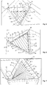
figure 4 , on a représenté une première stratégie de déplacement de l'outil de coupe 28 pour réaliser l'alvéole semi-finie 22. - Selon cette première stratégie de déplacement, l'alvéole semi-finie 22 est obtenue en réalisant plusieurs passes successives, parallèles au fond 24.
- Au départ, l'outil de coupe 28 est positionné au point A situé à l'aplomb et au-dessus d'un premier angle 46 prévu à l'extrémité d'une première paroi latérale 26.1. L'outil de coupe 28 effectue une première plongée, parallèle à l'axe Z, en pénétrant dans la matière sur une hauteur correspondant à la profondeur d'une passe (de l'ordre de quelques millimètres) jusqu'à un point B. Lors d'une première passe, l'outil de coupe 28 en conservant la même hauteur (position selon l'axe Z) suit des droites C1 à C7 parallèles à la première paroi latérale 26.1 en allant d'une deuxième paroi latérale 26.2 à une troisième paroi latérale 26.3, jusqu'à atteindre un point D situé au niveau du deuxième angle 48 opposé à la première paroi latérale 26.1. Au point D, l'outil de coupe 28 se déplace alors selon une direction parallèle à l'axe Z et pénètre dans la matière sur une hauteur correspondant à la profondeur de la passe jusqu'à un point E.
- Lors d'une deuxième passe, l'outil de coupe 28 suit, en conservant la même hauteur, des droites F1 à F6 parallèles à la deuxième paroi latérale 26.2 en allant de la troisième paroi latérale 26.3 à la première paroi latérale 26.1, jusqu'à atteindre un point G situé au niveau du deuxième angle 50 opposé à la deuxième paroi latérale 26.2.
- Au point G, l'outil de coupe 28 se déplace selon une direction parallèle à l'axe Z et pénètre dans la matière sur une hauteur correspondant à la profondeur de la passe. Lors d'une troisième passe, l'outil de coupe 28 suit, en conservant la même hauteur, des droites parallèles à la troisième paroi latérale 26.3 en allant de la première paroi latérale 26.1 à la deuxième paroi latérale 26.2, jusqu'à atteindre le premier angle 46 opposé à la troisième paroi latérale 26.3.
- Cette succession de passes est répétée jusqu'à atteindre le fond 24 de l'alvéole semi-finie 22.
- Sur la
figure 5 , on a représenté une deuxième stratégie de déplacement de l'outil de coupe 28 pour réaliser l'alvéole semi-finie 22. - Selon cette deuxième stratégie de déplacement, l'alvéole semi-finie 22 est obtenue en réalisant plusieurs passes successives, parallèles au fond 24.
- L'outil de coupe 28 est positionné à l'aplomb du centre I de l'alvéole semi-finie 22 juste au-dessus de la matière. L'outil de coupe 28 plonge alors dans la matière en combinant un mouvement parallèle à l'axe Z et un mouvement du centre I vers un premier angle 46 prévu à l'extrémité des première et deuxième parois latérales 26.1, 26.2 jusqu'à un point K disposé sur la bissectrice du premier angle 46 et dans le prolongement de l'axe de rotation A28 de l'outil de coupe 28 lorsqu'il est tangent aux première et deuxième parois latérales 26.1, 26.2. Ainsi, le point K est équidistant des première et deuxième parois latérales 26.1, 26.2 à une distance d sensiblement égale au diamètre de l'outil de coupe 28.
- Lors d'une première passe et en conservant la même hauteur, l'outil de coupe 28 effectue un balayage en suivant des droites H1 à H6 parallèles à la première paroi latérale 26.1, en allant d'une deuxième paroi latérale 26.2 à une troisième paroi latérale 26.3, jusqu'à atteindre le deuxième angle 48 opposé à la première paroi latérale 26.1. L'outil de coupe 28 effectue un lissage en se déplaçant successivement le long des trois parois latérales 26.1, 26.2, 26.3. Pour atteindre la passe suivante, l'outil de coupe 28 plonge dans la matière en combinant un mouvement parallèle à l'axe Z et un mouvement le long de la deuxième paroi latérale 26.2 jusqu'à atteindre le point K.
- Lors de chaque passe suivante, l'outil de coupe 28 effectue un balayage et un lissage identiques à la première passe.
- Sur la
figure 6 , on a représenté une troisième stratégie de déplacement de l'outil de coupe 28 pour réaliser l'alvéole semi-finie 22. - Selon cette troisième stratégie de déplacement, l'alvéole semi-finie 22 est obtenue en réalisant plusieurs passes successives, parallèles au fond 24.
- Au départ, l'outil de coupe 28 est positionné à l'aplomb du milieu M de la première paroi latérale 26.1. Pour atteindre la profondeur de la première passe, l'outil de coupe 28 plonge dans la matière en combinant un mouvement parallèle à l'axe Z et un mouvement le long de la première paroi 26.1 pour atteindre le premier angle 46.
- Lors de la première passe, l'outil de coupe 28 effectue un balayage en suivant des droites J1 à J10 perpendiculaires à la première paroi 26.1, en partant du premier angle 46 jusqu'au troisième angle 50, et un lissage en se déplaçant successivement le long des trois parois latérales 26.1, 26.2, 26.3.
- Pour atteindre la passe suivante, l'outil de coupe 28 plonge en combinant un mouvement parallèle à l'axe Z et un mouvement le long de la première paroi 26.1 pour atteindre le premier angle 46.
- Lors de chaque passe suivante, l'outil de coupe 28 effectue un balayage et un lissage identiques à la première passe.
- Sur la
figure 7 , on a représenté une quatrième stratégie de déplacement de l'outil de coupe 28 pour réaliser l'alvéole semi-finie 22. - Selon cette quatrième stratégie de déplacement, l'alvéole semi-finie 22 est obtenue en réalisant plusieurs passes successives, parallèles au fond 24.
- Au départ, l'outil de coupe 28 est positionné à l'aplomb du milieu M de la première paroi latérale 26.1. Pour atteindre la profondeur de la première passe, l'outil de coupe 28 plonge dans la matière en combinant un mouvement parallèle à l'axe Z et un mouvement le long de la première paroi 26.1 pour atteindre le premier angle 46.
- Lors de la première passe, l'outil de coupe 28 effectue un balayage en formant des triangles Tr1 à Tr6 juxtaposés qui ont un sommet positionné sur la bissectrice 54 du premier angle 46 et un côté opposé parallèle à la deuxième paroi latérale 26.2.
- A l'issue de la première passe, l'outil de coupe est repositionné à l'aplomb du milieu M de la première paroi latérale 26.1. Pour atteindre la profondeur de la passe suivante, l'outil de coupe 28 plonge dans la matière en combinant un mouvement parallèle à l'axe Z et un mouvement le long de la première paroi 26.1 pour atteindre le premier angle 46.
- Lors de chaque passe suivante, l'outil de coupe 28 décrit une trajectoire identique à la première passe.
- Sur la
figure 8 , on a représenté une cinquième stratégie de déplacement de l'outil de coupe 28 pour réaliser l'alvéole semi-finie 22. - Selon cette cinquième stratégie de déplacement, l'alvéole semi-finie 22 est obtenue en réalisant plusieurs passes successives, parallèles au fond 24.
- Au départ, l'outil de coupe 28 est positionné à l'aplomb du centre I de l'alvéole semi-finie 22 juste au-dessus de la matière. Pour atteindre la profondeur de la première passe, l'outil de coupe 28 plonge alors dans la matière en combinant un mouvement parallèle à l'axe Z et un mouvement du centre I vers un premier angle 46 prévu à l'extrémité d'une première paroi latérale 26.1.
- Lors de la première passe, l'outil de coupe 28 effectue un balayage en formant des triangles Tri1 à Tri8 en alternant un triangle de part et d'autre de la bissectrice 54 du premier angle 46 et en augmentant progressivement les dimensions des triangles Tri1 à Tri8.
- Sur la
figure 9 , on a représenté une sixième stratégie de déplacement de l'outil de coupe 28 pour réaliser l'alvéole semi-finie 22. Selon cette sixième stratégie de déplacement, l'alvéole semi-finie 22 est obtenue en réalisant plusieurs passes successives, parallèles au fond 24. - Au départ, l'outil de coupe 28 est positionné à l'aplomb et au-dessus du centre I de l'alvéole semi-finie 22. En suivant, il effectue une plongée en interpolation dans la matière jusqu'à atteindre le fond 24 pour former un puits approximativement au centre de l'alvéole semi-finie 22. Par interpolation, on entend que l'outil de coupe 28 combine deux mouvements de rotation, un premier mouvement de rotation autour de l'axe de rotation et un deuxième mouvement de rotation de l'axe de rotation autour d'un axe parallèle à l'axe de rotation. Dans le cas d'une plongée en interpolation, l'outil de coupe 28 combine deux mouvements de rotation et un mouvement de translation parallèle à l'axe Z.
- Lorsque l'outil de coupe 28 a atteint le fond 24, il revient à la hauteur de la première passe.
- Pour chaque passe, l'outil de coupe 28 se déplace en partant du centre 1 de l'alvéole semi-finie 22 et en décrivant des triangles concentriques. Entre chaque passe, l'outil de coupe 28 se repositionne dans le puits puis se translate parallèlement à l'axe Z, jusqu'à atteindre la hauteur de la passe suivante.
- Sur la
figure 10 , on a représenté une septième stratégie de déplacement de l'outil de coupe 28 pour réaliser l'alvéole semi-finie 22. - Selon cette septième stratégie de déplacement, l'alvéole semi-finie 22 est obtenue en réalisant plusieurs passes successives, parallèles au fond 24.
- Au départ, l'outil de coupe 28 est positionné à l'aplomb et au-dessus du centre I de l'alvéole semi-finie 22. Pour atteindre la profondeur de la première passe, il effectue une plongée en interpolation dans la matière, à proximité du centre I, pour atteindre la hauteur de la première passe.
- Lors de la première passe, l'outil de coupe 28 suit des trajectoires circulaires concentriques Ci1, Ci2 en partant du centre I et en augmentant progressivement le diamètre des cercles. Lorsque la trajectoire circulaire est sécante aux parois latérales 26.1, 26.2, 26.3, la trajectoire circulaire comprend des méplats M1 à M3. Lorsque les méplats M1 à M3 deviennent prépondérants, l'outil de coupe 28 effectue un lissage en se déplaçant successivement le long des trois parois latérales 26.1, 26.2, 26.3.
- A l'issue de la première passe, l'outil de coupe 28 est repositionné au niveau du centre I de l'alvéole semi-finie 22. Pour atteindre la profondeur de la passe suivante, l'outil de coupe 28 effectue une plongée en interpolation dans la matière pour atteindre la hauteur de la passe suivante.
- Lors de chaque passe suivante, l'outil de coupe 28 décrit une trajectoire identique à la première passe.
- Pour toutes les stratégies de déplacement, le passage d'une passe à l'autre est obtenu par une plongée en interpolation qui combine la rotation de l'outil autour de l'axe de rotation, un mouvement de rotation de l'axe de rotation autour d'un axe parallèle à l'axe de rotation et un mouvement de translation parallèle à l'axe Z. Selon une troisième variante, le passage d'une passe à l'autre est obtenu par une plongée en pente qui combine la rotation de l'outil autour de l'axe de rotation, un mouvement de translation selon une direction perpendiculaire à l'axe Z et un mouvement de translation parallèle à l'axe Z.
- De préférence, la pente de la plongée forme un angle d'environ 6 à 7° avec le fond 24. Lors de la longée en pente, l'outil se déplace le long de celle des parois latérales 26.1, 26.2, 26.3 qui correspond à la plus grande dimension de l'alvéole dans un plan perpendiculaire à l'axe Z. Selon une autre variante, la stratégie de déplacement comprend, préalablement aux passes, une plongée en interpolation sur toute la hauteur de l'alvéole intermédiaire 22 pour créer un puits (52) dans lequel se translate l'outil entre chaque passe.
Claims (7)
- Procédé d'usinage d'une alvéole d'un panneau raidi, ledit procédé comportant une phase d'ébauche réalisée en utilisant un outil de coupe (28) qui a un axe de rotation (A28) et un diamètre de l'ordre de 25 mm pour obtenir une alvéole intermédiaire (22) et une phase de finition pour obtenir une alvéole (16) finie à partir de l'alvéole intermédiaire (22), l'alvéole intermédiaire (22) étant délimitée par un fond (24) et des parois latérales (26.1, 26.2, 26.3), ledit procédé d'usinage étant caractérisé en ce que la phase d'ébauche comprend plusieurs passes successives parallèles au fond (24) et en ce que pour chaque passe, l'outil de coupe (28) effectue un balayage en suivant des droites (H1 à H6) parallèles à une première paroi latérale (26.1) jusqu'à atteindre un angle (48) opposé à la première paroi latérale (26.1), puis un lissage en se déplaçant successivement le long des parois latérales (26.1, 26.2, 26.3).
- Procédé d'usinage selon la revendication 1, caractérisé en ce qu'entre chaque passe, l'outil de coupe (28) plonge dans la matière en combinant un mouvement parallèle à l'axe de rotation (A28) et un mouvement le long d'une deuxième paroi latérale (26.2) jusqu'à atteindre un point (K) disposé dans le prolongement de l'axe de rotation (A28) de l'outil de coupe (28) lorsque ledit outil de coupe (28) est tangent aux première et deuxième parois latérales (26.1, 26.2).
- Procédé d'usinage selon l'une des revendications précédentes, caractérisé en ce qu'entre deux passes successives, l'outil de coupe (28) réalise une plongée qui combine une rotation de l'outil de coupe (28) autour de l'axe de rotation et un mouvement de translation perpendiculaire au fond (24).
- Procédé d'usinage selon l'une des revendications 1 à 2, caractérisé en ce qu'entre deux passes successives, l'outil de coupe (28) réalise une plongée en interpolation qui combine une rotation de l'outil de coupe (28) autour de l'axe de rotation, un mouvement de rotation de l'axe de rotation autour d'un axe parallèle à l'axe de rotation et un mouvement de translation perpendiculaire au fond (24).
- Procédé d'usinage selon l'une des revendications 1 à 2, caractérisé en ce qu'entre deux passes successives, l'outil de coupe (28) réalise une plongée en pente qui combine une rotation de l'outil de coupe (28) autour de l'axe de rotation, un mouvement de translation parallèle au fond (24) et un mouvement de translation perpendiculaire au fond (24).
- Procédé d'usinage selon la revendication précédente, caractérisé en ce que la plongée en pente a une pente qui forme un angle d'environ 6 à 7° avec le fond (24).
- Procédé d'usinage selon la revendication 1 ou 2, caractérisé en ce que préalablement aux passes, l'outil de coupe (28) réalise une plongée en interpolation sur toute la hauteur de l'alvéole intermédiaire (22) pour créer un puits dans lequel se translate l'outil de coupe (28) entre chaque passe.
Applications Claiming Priority (1)
| Application Number | Priority Date | Filing Date | Title |
|---|---|---|---|
| FR1660115A FR3057480B1 (fr) | 2016-10-19 | 2016-10-19 | Procede d'usinage d'une alveole d'un panneau raidi |
Publications (2)
| Publication Number | Publication Date |
|---|---|
| EP3311944A1 true EP3311944A1 (fr) | 2018-04-25 |
| EP3311944B1 EP3311944B1 (fr) | 2022-06-01 |
Family
ID=57750195
Family Applications (1)
| Application Number | Title | Priority Date | Filing Date |
|---|---|---|---|
| EP17192664.5A Active EP3311944B1 (fr) | 2016-10-19 | 2017-09-22 | Procede d'usinage d'une alveole d'un panneau raidi |
Country Status (2)
| Country | Link |
|---|---|
| EP (1) | EP3311944B1 (fr) |
| FR (1) | FR3057480B1 (fr) |
Cited By (1)
| Publication number | Priority date | Publication date | Assignee | Title |
|---|---|---|---|---|
| US11027341B2 (en) * | 2016-01-06 | 2021-06-08 | Kanefusa Kabushiki Kaisha | Dimple processing method using rotary cutting tool, and rotary cutting tool for dimple processing |
Families Citing this family (1)
| Publication number | Priority date | Publication date | Assignee | Title |
|---|---|---|---|---|
| FR3097790B1 (fr) | 2019-06-25 | 2021-07-16 | Airbus Operations Sas | Procédé de fabrication d’un panneau renforcé présentant une structure alvéolaire et au moins un réseau de drainage, panneau renforcé ainsi obtenu |
Citations (4)
| Publication number | Priority date | Publication date | Assignee | Title |
|---|---|---|---|---|
| US6352496B1 (en) * | 2000-01-28 | 2002-03-05 | Imta Manufacturing Technology & Automation Company | High-speed milling machine with rotary table |
| WO2002066189A1 (fr) * | 2001-02-23 | 2002-08-29 | Incs Inc. | Procede de fraisage utilisant un outil rotatif |
| EP1595638A1 (fr) * | 2004-05-13 | 2005-11-16 | ROLLS-ROYCE plc | Procédé de fabrication de structures composites isogrilles à parois minces |
| EP2036670A2 (fr) * | 2007-09-13 | 2009-03-18 | United Technologies Corporation | Outil superabrasif et procédés d'usinage |
-
2016
- 2016-10-19 FR FR1660115A patent/FR3057480B1/fr not_active Expired - Fee Related
-
2017
- 2017-09-22 EP EP17192664.5A patent/EP3311944B1/fr active Active
Patent Citations (4)
| Publication number | Priority date | Publication date | Assignee | Title |
|---|---|---|---|---|
| US6352496B1 (en) * | 2000-01-28 | 2002-03-05 | Imta Manufacturing Technology & Automation Company | High-speed milling machine with rotary table |
| WO2002066189A1 (fr) * | 2001-02-23 | 2002-08-29 | Incs Inc. | Procede de fraisage utilisant un outil rotatif |
| EP1595638A1 (fr) * | 2004-05-13 | 2005-11-16 | ROLLS-ROYCE plc | Procédé de fabrication de structures composites isogrilles à parois minces |
| EP2036670A2 (fr) * | 2007-09-13 | 2009-03-18 | United Technologies Corporation | Outil superabrasif et procédés d'usinage |
Cited By (1)
| Publication number | Priority date | Publication date | Assignee | Title |
|---|---|---|---|---|
| US11027341B2 (en) * | 2016-01-06 | 2021-06-08 | Kanefusa Kabushiki Kaisha | Dimple processing method using rotary cutting tool, and rotary cutting tool for dimple processing |
Also Published As
| Publication number | Publication date |
|---|---|
| FR3057480A1 (fr) | 2018-04-20 |
| EP3311944B1 (fr) | 2022-06-01 |
| FR3057480B1 (fr) | 2018-10-12 |
Similar Documents
| Publication | Publication Date | Title |
|---|---|---|
| EP1944129B1 (fr) | Pince multiprise entrepassée à réglage fin | |
| CH538320A (fr) | Engrenage et procédé pour sa fabrication | |
| CA2373148C (fr) | Procede de fabrication d'une surface d'une lentille ophtalmique, installation de mise en oeuvre du procede et lentille ophtalmique obtenue selon le procede | |
| EP2618772A1 (fr) | Instrument endodontique dont la partie active présente une fente formant passage pour un fluide | |
| EP3311944B1 (fr) | Procede d'usinage d'une alveole d'un panneau raidi | |
| WO2012059670A2 (fr) | Procédé d'usinage d'un carter d'un turbomoteur d'aéronef et outil de grattoir pour la mise en oeuvre du procédé | |
| EP2864067B1 (fr) | Procédé de crantage de tube, et machine de crantage associée | |
| FR3042995A1 (fr) | Outil de fraisage avec compensation de plaquettes | |
| FR3001163A1 (fr) | Dispositif de cintrage de profiles tels que des tubes | |
| EP2677957B1 (fr) | Instrument canalaire du type alésoir | |
| US20170368624A1 (en) | Cutting tip, cutting tool and gear edge cut-off device | |
| FR3042994A1 (fr) | Procede de fraisage d'un alesage de moteur | |
| WO2006042929A1 (fr) | Lame de scie a denture et a pas variable | |
| FR3042996A1 (fr) | Outil de fraisage avec une rugosite augmentee | |
| WO2003078921A2 (fr) | Dispositif de contrôle de la géométrie d'un profile forme | |
| EP0041432B1 (fr) | Appareil de façonnage de tubes | |
| CH650724A5 (fr) | Procede de fabrication d'un support tronconique, utilisable notamment pour le bobinage de fils et/ou de rubans textiles. | |
| JP2006046423A (ja) | ラックシャフトおよびその製造方法 | |
| FR2684124A1 (fr) | Coffrage en carton et son procede de fabrication. | |
| US20170259360A1 (en) | Gear edge cut-off tool and gear edge cut-off device | |
| EP1762372A1 (fr) | Dispositif pour la réalisation d'une lentille optique en matiére synthétique polymérisable | |
| FR2491790A1 (fr) | Ensemble d'outils de formage de dents, tels que dents de cannelures ou d'engrenages | |
| EP1747834A9 (fr) | Canal de refroidissement menage dans une paroi | |
| FR2489727A1 (fr) | Outil de coupe rotatif | |
| CN108555519A (zh) | 针对不规则物体的可旋转夹具 |
Legal Events
| Date | Code | Title | Description |
|---|---|---|---|
| PUAI | Public reference made under article 153(3) epc to a published international application that has entered the european phase |
Free format text: ORIGINAL CODE: 0009012 |
|
| STAA | Information on the status of an ep patent application or granted ep patent |
Free format text: STATUS: THE APPLICATION HAS BEEN PUBLISHED |
|
| AK | Designated contracting states |
Kind code of ref document: A1 Designated state(s): AL AT BE BG CH CY CZ DE DK EE ES FI FR GB GR HR HU IE IS IT LI LT LU LV MC MK MT NL NO PL PT RO RS SE SI SK SM TR |
|
| AX | Request for extension of the european patent |
Extension state: BA ME |
|
| STAA | Information on the status of an ep patent application or granted ep patent |
Free format text: STATUS: REQUEST FOR EXAMINATION WAS MADE |
|
| 17P | Request for examination filed |
Effective date: 20181025 |
|
| RBV | Designated contracting states (corrected) |
Designated state(s): AL AT BE BG CH CY CZ DE DK EE ES FI FR GB GR HR HU IE IS IT LI LT LU LV MC MK MT NL NO PL PT RO RS SE SI SK SM TR |
|
| GRAP | Despatch of communication of intention to grant a patent |
Free format text: ORIGINAL CODE: EPIDOSNIGR1 |
|
| STAA | Information on the status of an ep patent application or granted ep patent |
Free format text: STATUS: GRANT OF PATENT IS INTENDED |
|
| INTG | Intention to grant announced |
Effective date: 20220315 |
|
| GRAA | (expected) grant |
Free format text: ORIGINAL CODE: 0009210 |
|
| GRAS | Grant fee paid |
Free format text: ORIGINAL CODE: EPIDOSNIGR3 |
|
| STAA | Information on the status of an ep patent application or granted ep patent |
Free format text: STATUS: THE PATENT HAS BEEN GRANTED |
|
| AK | Designated contracting states |
Kind code of ref document: B1 Designated state(s): AL AT BE BG CH CY CZ DE DK EE ES FI FR GB GR HR HU IE IS IT LI LT LU LV MC MK MT NL NO PL PT RO RS SE SI SK SM TR |
|
| REG | Reference to a national code |
Ref country code: GB Ref legal event code: FG4D Free format text: NOT ENGLISH |
|
| REG | Reference to a national code |
Ref country code: AT Ref legal event code: REF Ref document number: 1495034 Country of ref document: AT Kind code of ref document: T Effective date: 20220615 Ref country code: CH Ref legal event code: EP |
|
| REG | Reference to a national code |
Ref country code: IE Ref legal event code: FG4D Free format text: LANGUAGE OF EP DOCUMENT: FRENCH |
|
| REG | Reference to a national code |
Ref country code: DE Ref legal event code: R096 Ref document number: 602017057948 Country of ref document: DE |
|
| REG | Reference to a national code |
Ref country code: LT Ref legal event code: MG9D |
|
| REG | Reference to a national code |
Ref country code: NL Ref legal event code: MP Effective date: 20220601 |
|
| PG25 | Lapsed in a contracting state [announced via postgrant information from national office to epo] |
Ref country code: SE Free format text: LAPSE BECAUSE OF FAILURE TO SUBMIT A TRANSLATION OF THE DESCRIPTION OR TO PAY THE FEE WITHIN THE PRESCRIBED TIME-LIMIT Effective date: 20220601 Ref country code: NO Free format text: LAPSE BECAUSE OF FAILURE TO SUBMIT A TRANSLATION OF THE DESCRIPTION OR TO PAY THE FEE WITHIN THE PRESCRIBED TIME-LIMIT Effective date: 20220901 Ref country code: LT Free format text: LAPSE BECAUSE OF FAILURE TO SUBMIT A TRANSLATION OF THE DESCRIPTION OR TO PAY THE FEE WITHIN THE PRESCRIBED TIME-LIMIT Effective date: 20220601 Ref country code: HR Free format text: LAPSE BECAUSE OF FAILURE TO SUBMIT A TRANSLATION OF THE DESCRIPTION OR TO PAY THE FEE WITHIN THE PRESCRIBED TIME-LIMIT Effective date: 20220601 Ref country code: GR Free format text: LAPSE BECAUSE OF FAILURE TO SUBMIT A TRANSLATION OF THE DESCRIPTION OR TO PAY THE FEE WITHIN THE PRESCRIBED TIME-LIMIT Effective date: 20220902 Ref country code: FI Free format text: LAPSE BECAUSE OF FAILURE TO SUBMIT A TRANSLATION OF THE DESCRIPTION OR TO PAY THE FEE WITHIN THE PRESCRIBED TIME-LIMIT Effective date: 20220601 Ref country code: ES Free format text: LAPSE BECAUSE OF FAILURE TO SUBMIT A TRANSLATION OF THE DESCRIPTION OR TO PAY THE FEE WITHIN THE PRESCRIBED TIME-LIMIT Effective date: 20220601 Ref country code: BG Free format text: LAPSE BECAUSE OF FAILURE TO SUBMIT A TRANSLATION OF THE DESCRIPTION OR TO PAY THE FEE WITHIN THE PRESCRIBED TIME-LIMIT Effective date: 20220901 |
|
| REG | Reference to a national code |
Ref country code: AT Ref legal event code: MK05 Ref document number: 1495034 Country of ref document: AT Kind code of ref document: T Effective date: 20220601 |
|
| PG25 | Lapsed in a contracting state [announced via postgrant information from national office to epo] |
Ref country code: RS Free format text: LAPSE BECAUSE OF FAILURE TO SUBMIT A TRANSLATION OF THE DESCRIPTION OR TO PAY THE FEE WITHIN THE PRESCRIBED TIME-LIMIT Effective date: 20220601 Ref country code: PL Free format text: LAPSE BECAUSE OF FAILURE TO SUBMIT A TRANSLATION OF THE DESCRIPTION OR TO PAY THE FEE WITHIN THE PRESCRIBED TIME-LIMIT Effective date: 20220601 Ref country code: LV Free format text: LAPSE BECAUSE OF FAILURE TO SUBMIT A TRANSLATION OF THE DESCRIPTION OR TO PAY THE FEE WITHIN THE PRESCRIBED TIME-LIMIT Effective date: 20220601 |
|
| PG25 | Lapsed in a contracting state [announced via postgrant information from national office to epo] |
Ref country code: NL Free format text: LAPSE BECAUSE OF FAILURE TO SUBMIT A TRANSLATION OF THE DESCRIPTION OR TO PAY THE FEE WITHIN THE PRESCRIBED TIME-LIMIT Effective date: 20220601 |
|
| PG25 | Lapsed in a contracting state [announced via postgrant information from national office to epo] |
Ref country code: SM Free format text: LAPSE BECAUSE OF FAILURE TO SUBMIT A TRANSLATION OF THE DESCRIPTION OR TO PAY THE FEE WITHIN THE PRESCRIBED TIME-LIMIT Effective date: 20220601 Ref country code: SK Free format text: LAPSE BECAUSE OF FAILURE TO SUBMIT A TRANSLATION OF THE DESCRIPTION OR TO PAY THE FEE WITHIN THE PRESCRIBED TIME-LIMIT Effective date: 20220601 Ref country code: RO Free format text: LAPSE BECAUSE OF FAILURE TO SUBMIT A TRANSLATION OF THE DESCRIPTION OR TO PAY THE FEE WITHIN THE PRESCRIBED TIME-LIMIT Effective date: 20220601 Ref country code: PT Free format text: LAPSE BECAUSE OF FAILURE TO SUBMIT A TRANSLATION OF THE DESCRIPTION OR TO PAY THE FEE WITHIN THE PRESCRIBED TIME-LIMIT Effective date: 20221003 Ref country code: EE Free format text: LAPSE BECAUSE OF FAILURE TO SUBMIT A TRANSLATION OF THE DESCRIPTION OR TO PAY THE FEE WITHIN THE PRESCRIBED TIME-LIMIT Effective date: 20220601 Ref country code: CZ Free format text: LAPSE BECAUSE OF FAILURE TO SUBMIT A TRANSLATION OF THE DESCRIPTION OR TO PAY THE FEE WITHIN THE PRESCRIBED TIME-LIMIT Effective date: 20220601 Ref country code: AT Free format text: LAPSE BECAUSE OF FAILURE TO SUBMIT A TRANSLATION OF THE DESCRIPTION OR TO PAY THE FEE WITHIN THE PRESCRIBED TIME-LIMIT Effective date: 20220601 |
|
| PG25 | Lapsed in a contracting state [announced via postgrant information from national office to epo] |
Ref country code: IS Free format text: LAPSE BECAUSE OF FAILURE TO SUBMIT A TRANSLATION OF THE DESCRIPTION OR TO PAY THE FEE WITHIN THE PRESCRIBED TIME-LIMIT Effective date: 20221001 |
|
| REG | Reference to a national code |
Ref country code: DE Ref legal event code: R097 Ref document number: 602017057948 Country of ref document: DE |
|
| PG25 | Lapsed in a contracting state [announced via postgrant information from national office to epo] |
Ref country code: AL Free format text: LAPSE BECAUSE OF FAILURE TO SUBMIT A TRANSLATION OF THE DESCRIPTION OR TO PAY THE FEE WITHIN THE PRESCRIBED TIME-LIMIT Effective date: 20220601 |
|
| PLBE | No opposition filed within time limit |
Free format text: ORIGINAL CODE: 0009261 |
|
| STAA | Information on the status of an ep patent application or granted ep patent |
Free format text: STATUS: NO OPPOSITION FILED WITHIN TIME LIMIT |
|
| PG25 | Lapsed in a contracting state [announced via postgrant information from national office to epo] |
Ref country code: MC Free format text: LAPSE BECAUSE OF FAILURE TO SUBMIT A TRANSLATION OF THE DESCRIPTION OR TO PAY THE FEE WITHIN THE PRESCRIBED TIME-LIMIT Effective date: 20220601 Ref country code: DK Free format text: LAPSE BECAUSE OF FAILURE TO SUBMIT A TRANSLATION OF THE DESCRIPTION OR TO PAY THE FEE WITHIN THE PRESCRIBED TIME-LIMIT Effective date: 20220601 |
|
| REG | Reference to a national code |
Ref country code: CH Ref legal event code: PL |
|
| 26N | No opposition filed |
Effective date: 20230302 |
|
| REG | Reference to a national code |
Ref country code: BE Ref legal event code: MM Effective date: 20220930 |
|
| PG25 | Lapsed in a contracting state [announced via postgrant information from national office to epo] |
Ref country code: SI Free format text: LAPSE BECAUSE OF FAILURE TO SUBMIT A TRANSLATION OF THE DESCRIPTION OR TO PAY THE FEE WITHIN THE PRESCRIBED TIME-LIMIT Effective date: 20220601 |
|
| PG25 | Lapsed in a contracting state [announced via postgrant information from national office to epo] |
Ref country code: LU Free format text: LAPSE BECAUSE OF NON-PAYMENT OF DUE FEES Effective date: 20220922 |
|
| PG25 | Lapsed in a contracting state [announced via postgrant information from national office to epo] |
Ref country code: LI Free format text: LAPSE BECAUSE OF NON-PAYMENT OF DUE FEES Effective date: 20220930 Ref country code: IE Free format text: LAPSE BECAUSE OF NON-PAYMENT OF DUE FEES Effective date: 20220922 Ref country code: CH Free format text: LAPSE BECAUSE OF NON-PAYMENT OF DUE FEES Effective date: 20220930 |
|
| PG25 | Lapsed in a contracting state [announced via postgrant information from national office to epo] |
Ref country code: BE Free format text: LAPSE BECAUSE OF NON-PAYMENT OF DUE FEES Effective date: 20220930 |
|
| PG25 | Lapsed in a contracting state [announced via postgrant information from national office to epo] |
Ref country code: IT Free format text: LAPSE BECAUSE OF FAILURE TO SUBMIT A TRANSLATION OF THE DESCRIPTION OR TO PAY THE FEE WITHIN THE PRESCRIBED TIME-LIMIT Effective date: 20220601 |
|
| PG25 | Lapsed in a contracting state [announced via postgrant information from national office to epo] |
Ref country code: HU Free format text: LAPSE BECAUSE OF FAILURE TO SUBMIT A TRANSLATION OF THE DESCRIPTION OR TO PAY THE FEE WITHIN THE PRESCRIBED TIME-LIMIT; INVALID AB INITIO Effective date: 20170922 |
|
| PG25 | Lapsed in a contracting state [announced via postgrant information from national office to epo] |
Ref country code: CY Free format text: LAPSE BECAUSE OF FAILURE TO SUBMIT A TRANSLATION OF THE DESCRIPTION OR TO PAY THE FEE WITHIN THE PRESCRIBED TIME-LIMIT Effective date: 20220601 |
|
| PG25 | Lapsed in a contracting state [announced via postgrant information from national office to epo] |
Ref country code: MK Free format text: LAPSE BECAUSE OF FAILURE TO SUBMIT A TRANSLATION OF THE DESCRIPTION OR TO PAY THE FEE WITHIN THE PRESCRIBED TIME-LIMIT Effective date: 20220601 |
|
| PG25 | Lapsed in a contracting state [announced via postgrant information from national office to epo] |
Ref country code: MT Free format text: LAPSE BECAUSE OF FAILURE TO SUBMIT A TRANSLATION OF THE DESCRIPTION OR TO PAY THE FEE WITHIN THE PRESCRIBED TIME-LIMIT Effective date: 20220601 |
|
| PG25 | Lapsed in a contracting state [announced via postgrant information from national office to epo] |
Ref country code: BG Free format text: LAPSE BECAUSE OF FAILURE TO SUBMIT A TRANSLATION OF THE DESCRIPTION OR TO PAY THE FEE WITHIN THE PRESCRIBED TIME-LIMIT Effective date: 20220601 |
|
| PG25 | Lapsed in a contracting state [announced via postgrant information from national office to epo] |
Ref country code: BG Free format text: LAPSE BECAUSE OF FAILURE TO SUBMIT A TRANSLATION OF THE DESCRIPTION OR TO PAY THE FEE WITHIN THE PRESCRIBED TIME-LIMIT Effective date: 20220601 |
|
| PGFP | Annual fee paid to national office [announced via postgrant information from national office to epo] |
Ref country code: DE Payment date: 20250919 Year of fee payment: 9 |
|
| PGFP | Annual fee paid to national office [announced via postgrant information from national office to epo] |
Ref country code: GB Payment date: 20250919 Year of fee payment: 9 |
|
| PGFP | Annual fee paid to national office [announced via postgrant information from national office to epo] |
Ref country code: FR Payment date: 20250922 Year of fee payment: 9 |
|
| PG25 | Lapsed in a contracting state [announced via postgrant information from national office to epo] |
Ref country code: TR Free format text: LAPSE BECAUSE OF FAILURE TO SUBMIT A TRANSLATION OF THE DESCRIPTION OR TO PAY THE FEE WITHIN THE PRESCRIBED TIME-LIMIT Effective date: 20220601 |