EP3311870B1 - Apparatus for generating nitric oxide for medical use - Google Patents
Apparatus for generating nitric oxide for medical use Download PDFInfo
- Publication number
- EP3311870B1 EP3311870B1 EP17194639.5A EP17194639A EP3311870B1 EP 3311870 B1 EP3311870 B1 EP 3311870B1 EP 17194639 A EP17194639 A EP 17194639A EP 3311870 B1 EP3311870 B1 EP 3311870B1
- Authority
- EP
- European Patent Office
- Prior art keywords
- patient
- reaction chamber
- reaction
- liquid
- gas
- Prior art date
- Legal status (The legal status is an assumption and is not a legal conclusion. Google has not performed a legal analysis and makes no representation as to the accuracy of the status listed.)
- Active
Links
Images



Classifications
-
- A—HUMAN NECESSITIES
- A61—MEDICAL OR VETERINARY SCIENCE; HYGIENE
- A61M—DEVICES FOR INTRODUCING MEDIA INTO, OR ONTO, THE BODY; DEVICES FOR TRANSDUCING BODY MEDIA OR FOR TAKING MEDIA FROM THE BODY; DEVICES FOR PRODUCING OR ENDING SLEEP OR STUPOR
- A61M16/00—Devices for influencing the respiratory system of patients by gas treatment, e.g. ventilators; Tracheal tubes
- A61M16/10—Preparation of respiratory gases or vapours
-
- A—HUMAN NECESSITIES
- A61—MEDICAL OR VETERINARY SCIENCE; HYGIENE
- A61K—PREPARATIONS FOR MEDICAL, DENTAL OR TOILETRY PURPOSES
- A61K33/00—Medicinal preparations containing inorganic active ingredients
-
- A—HUMAN NECESSITIES
- A61—MEDICAL OR VETERINARY SCIENCE; HYGIENE
- A61M—DEVICES FOR INTRODUCING MEDIA INTO, OR ONTO, THE BODY; DEVICES FOR TRANSDUCING BODY MEDIA OR FOR TAKING MEDIA FROM THE BODY; DEVICES FOR PRODUCING OR ENDING SLEEP OR STUPOR
- A61M16/00—Devices for influencing the respiratory system of patients by gas treatment, e.g. ventilators; Tracheal tubes
- A61M16/0003—Accessories therefor, e.g. sensors, vibrators, negative pressure
-
- A—HUMAN NECESSITIES
- A61—MEDICAL OR VETERINARY SCIENCE; HYGIENE
- A61M—DEVICES FOR INTRODUCING MEDIA INTO, OR ONTO, THE BODY; DEVICES FOR TRANSDUCING BODY MEDIA OR FOR TAKING MEDIA FROM THE BODY; DEVICES FOR PRODUCING OR ENDING SLEEP OR STUPOR
- A61M16/00—Devices for influencing the respiratory system of patients by gas treatment, e.g. ventilators; Tracheal tubes
- A61M16/0057—Pumps therefor
-
- A—HUMAN NECESSITIES
- A61—MEDICAL OR VETERINARY SCIENCE; HYGIENE
- A61M—DEVICES FOR INTRODUCING MEDIA INTO, OR ONTO, THE BODY; DEVICES FOR TRANSDUCING BODY MEDIA OR FOR TAKING MEDIA FROM THE BODY; DEVICES FOR PRODUCING OR ENDING SLEEP OR STUPOR
- A61M16/00—Devices for influencing the respiratory system of patients by gas treatment, e.g. ventilators; Tracheal tubes
- A61M16/10—Preparation of respiratory gases or vapours
- A61M16/105—Filters
- A61M16/106—Filters in a path
- A61M16/107—Filters in a path in the inspiratory path
-
- A—HUMAN NECESSITIES
- A61—MEDICAL OR VETERINARY SCIENCE; HYGIENE
- A61P—SPECIFIC THERAPEUTIC ACTIVITY OF CHEMICAL COMPOUNDS OR MEDICINAL PREPARATIONS
- A61P11/00—Drugs for disorders of the respiratory system
-
- A—HUMAN NECESSITIES
- A61—MEDICAL OR VETERINARY SCIENCE; HYGIENE
- A61P—SPECIFIC THERAPEUTIC ACTIVITY OF CHEMICAL COMPOUNDS OR MEDICINAL PREPARATIONS
- A61P11/00—Drugs for disorders of the respiratory system
- A61P11/06—Antiasthmatics
-
- A—HUMAN NECESSITIES
- A61—MEDICAL OR VETERINARY SCIENCE; HYGIENE
- A61M—DEVICES FOR INTRODUCING MEDIA INTO, OR ONTO, THE BODY; DEVICES FOR TRANSDUCING BODY MEDIA OR FOR TAKING MEDIA FROM THE BODY; DEVICES FOR PRODUCING OR ENDING SLEEP OR STUPOR
- A61M16/00—Devices for influencing the respiratory system of patients by gas treatment, e.g. ventilators; Tracheal tubes
- A61M16/0003—Accessories therefor, e.g. sensors, vibrators, negative pressure
- A61M2016/0015—Accessories therefor, e.g. sensors, vibrators, negative pressure inhalation detectors
- A61M2016/0018—Accessories therefor, e.g. sensors, vibrators, negative pressure inhalation detectors electrical
- A61M2016/0021—Accessories therefor, e.g. sensors, vibrators, negative pressure inhalation detectors electrical with a proportional output signal, e.g. from a thermistor
-
- A—HUMAN NECESSITIES
- A61—MEDICAL OR VETERINARY SCIENCE; HYGIENE
- A61M—DEVICES FOR INTRODUCING MEDIA INTO, OR ONTO, THE BODY; DEVICES FOR TRANSDUCING BODY MEDIA OR FOR TAKING MEDIA FROM THE BODY; DEVICES FOR PRODUCING OR ENDING SLEEP OR STUPOR
- A61M16/00—Devices for influencing the respiratory system of patients by gas treatment, e.g. ventilators; Tracheal tubes
- A61M16/0003—Accessories therefor, e.g. sensors, vibrators, negative pressure
- A61M2016/003—Accessories therefor, e.g. sensors, vibrators, negative pressure with a flowmeter
-
- A—HUMAN NECESSITIES
- A61—MEDICAL OR VETERINARY SCIENCE; HYGIENE
- A61M—DEVICES FOR INTRODUCING MEDIA INTO, OR ONTO, THE BODY; DEVICES FOR TRANSDUCING BODY MEDIA OR FOR TAKING MEDIA FROM THE BODY; DEVICES FOR PRODUCING OR ENDING SLEEP OR STUPOR
- A61M16/00—Devices for influencing the respiratory system of patients by gas treatment, e.g. ventilators; Tracheal tubes
- A61M16/0003—Accessories therefor, e.g. sensors, vibrators, negative pressure
- A61M2016/003—Accessories therefor, e.g. sensors, vibrators, negative pressure with a flowmeter
- A61M2016/0033—Accessories therefor, e.g. sensors, vibrators, negative pressure with a flowmeter electrical
- A61M2016/0039—Accessories therefor, e.g. sensors, vibrators, negative pressure with a flowmeter electrical in the inspiratory circuit
-
- A—HUMAN NECESSITIES
- A61—MEDICAL OR VETERINARY SCIENCE; HYGIENE
- A61M—DEVICES FOR INTRODUCING MEDIA INTO, OR ONTO, THE BODY; DEVICES FOR TRANSDUCING BODY MEDIA OR FOR TAKING MEDIA FROM THE BODY; DEVICES FOR PRODUCING OR ENDING SLEEP OR STUPOR
- A61M16/00—Devices for influencing the respiratory system of patients by gas treatment, e.g. ventilators; Tracheal tubes
- A61M16/10—Preparation of respiratory gases or vapours
- A61M16/1005—Preparation of respiratory gases or vapours with O2 features or with parameter measurement
- A61M2016/102—Measuring a parameter of the content of the delivered gas
-
- A—HUMAN NECESSITIES
- A61—MEDICAL OR VETERINARY SCIENCE; HYGIENE
- A61M—DEVICES FOR INTRODUCING MEDIA INTO, OR ONTO, THE BODY; DEVICES FOR TRANSDUCING BODY MEDIA OR FOR TAKING MEDIA FROM THE BODY; DEVICES FOR PRODUCING OR ENDING SLEEP OR STUPOR
- A61M2202/00—Special media to be introduced, removed or treated
- A61M2202/02—Gases
- A61M2202/0266—Nitrogen (N)
- A61M2202/0275—Nitric oxide [NO]
-
- A—HUMAN NECESSITIES
- A61—MEDICAL OR VETERINARY SCIENCE; HYGIENE
- A61M—DEVICES FOR INTRODUCING MEDIA INTO, OR ONTO, THE BODY; DEVICES FOR TRANSDUCING BODY MEDIA OR FOR TAKING MEDIA FROM THE BODY; DEVICES FOR PRODUCING OR ENDING SLEEP OR STUPOR
- A61M2205/00—General characteristics of the apparatus
- A61M2205/33—Controlling, regulating or measuring
Definitions
- the present invention relates to a system for generating and administering nitric oxide (NO) to a patient, and, more particularly, to a system that generates the NO proximate to and for immediate delivery to the patient.
- NO nitric oxide
- nitric oxide (NO) gas via inhalation for treating patients with pulmonary hypertension is described in Zapol and Frostell's US patent 5,485,827 "Methods and Devices for Treating Pulmonary Vasoconstriction and Asthma".
- nitric oxide gas is commonly used for the treatment of persistent pulmonary hypertension in the newborn and is indicated for the treatment of term and near-term (>34 weeks) neonates with hypoxic respiratory failure (HRF) associated with clinical or echocardiographic evidence of pulmonary hypertension.
- HRF hypoxic respiratory failure
- blood vessels in the lungs constrict, making it difficult for the heart to pump blood through the lungs for oxygenation.
- Nitric oxide is a pulmonary vasodilator, which relaxes the blood vessels of the lungs in newborns whose heart and lungs could not otherwise carry enough oxygenated blood to the body tissues.
- Nitric oxide readily combines with oxygen (O 2 ) to form nitrogen dioxide (NO 2 ), a known toxic gas, so it is very important that the gas cylinder does not become contaminated with oxygen. It is for this reason that the diluent gas used in the cylinders is one that is inert to, i.e. will not oxidize, nitric oxide. While a number of such inert gases are known, it is preferred to utilize nitrogen, N 2 , primarily on the basis of cost.
- the delivery apparatus for dispensing gaseous NO has to deliver the NO source gas into the patient's respirable gas to give a concentration in the range of 1-80 ppm to the patient's lung in a precise and controllable manner. It also has to deliver it in a manner that minimizes the formation of NO 2 .
- the parameters that are relevant to the formation of NO 2 are the square of the NO concentration, the O 2 concentration and the time for the reaction between them to take place.
- the O 2 concentration is not normally controllable by the NO delivery device and the source gas is at a fixed concentration, therefore, the time for the reaction to take place is the only variable.
- Apparatus for the delivery of nitric oxide (NO) from a gas cylinder has to not only precisely deliver the correct dose of NO to the patient, but also to minimize the time from delivery to when the patient breathes in the gas to prevent the formation of NO 2 at unsafe levels.
- An example of a bedside NO delivery device that achieves these two functions is described in U.S. Patent US 5,558,083 which shows how a constant concentration of NO can be delivered to a patient who is on a gas delivery system such as a ventilator.
- alternate solutions include using an electric arc discharge to produce NO from air prior to delivering it to a patient ( US 5,396,882 ): producing NO for inhalation by establishing a coulometric reduction of copper ions in a solution of nitric acid along with purging the chamber with an inert gas ( US 5,827,420 ); using a corona discharge to generate NO in a chamber that contains oxygen and nitrogen ( EP 0719159 ); using a plasma chemical reaction method while heating the reaction chamber to 400-800°C to obtain high efficiency of NO production ( US 6,296,827 ); and using heat to break down an organic nitrogen-containing compound, such as ammonia, to form NO ( US 6,758,214 ).
- an electric arc discharge to produce NO from air prior to delivering it to a patient
- a general aspect of the invention is a method for producing nitric oxide (NO) for the immediate delivery to a mammal, i.e. human or animal by bringing together controllable quantities of a nitrite salt, preferably sodium nitrite, and a reductant, preferably at least one of ascorbic acid and maleic acid, in the presence of water in the desired quantities to produce the amount of NO required by the mammal and for the NO to then be immediately delivered to the mammal.
- NO nitric oxide
- NO produced in accordance with the present invention is delivered for inhalation by the mammal.
- the time for NO 2 formation is kept to a minimum.
- the present invention uses a nitrite and a reductant in the presence of water to generate NO in gaseous form.
- the nitrite source is sodium nitrite and the reductant is at least one of ascorbic acid and maleic acid, preferably ascorbic acid.
- ascorbic acid is Vitamin C
- sodium nitrite is used in curing meats, such as ham, and the like. Therefore, the reactant compounds can be used in proximity to the patient without the danger of toxic materials passing downstream to ultimately reach the patient.
- the term "patient” refers to a human or an animal, preferably the former.
- Equation 1 2 NaNO 2 + 2 C 6 H 8 O 6 ⁇ 2 ⁇ NO + 2 NaC 6 H 7 O 6 + H 2 O + 1 2 O 2
- the reactant compounds used to generate NO according to Equation 1 are widely used in the food industry and are non-toxic in the quantities contemplated herein as described above.
- One embodiment of the invention is an apparatus that uses an aqueous solution of sodium nitrite that is deposited as liquid droplets in a controlled amount onto an molar excess of ascorbic acid (in solid form or as an aqueous solution).
- aqueous solution of sodium nitrite that is deposited as liquid droplets in a controlled amount onto an molar excess of ascorbic acid (in solid form or as an aqueous solution).
- ascorbic acid in solid form or as an aqueous solution.
- very fine droplets are utilized, thus enabling the reaction to proceed quickly and the NO thus-formed available for inhalation or application.
- the amount of NO provided from the reaction is governed by controlling a precise amount of liquid to be brought into contact with the other reactant or reactants.
- the liquid being dispensed into the reaction chamber is preferably aqueous solutions of the nitrite and/or the reductant. If both the nitrite and the reductant are in a solid state on a substrate, the liquid dispensed to initiate and control the reaction will be water.
- the aqueous solutions utilized to generate NO in accordance with the present invention may contain different molar strengths of sodium nitrite with the size of the liquid reservoir required varying inversely with the molar concentration. For instance, utilizing a 6 molar aqueous solution of sodium nitrite, the amount of solution that would produce the same number of moles of NO as are contained in the 16 L cylinder described above would be just 12 mL and weigh only 12.4 grams. Given a plastic package/housing for the solution (similar to an inkjet printer cartridge), the size would be approximately 30mm x 45mm x 45 mm and weigh around 20 gms, or a total weight of 33 grams. As can be seen compared with the gas cylinder for NO, this gives significant improvement with regard to the drug package size and weight.
- Equation (3) can be used to calculate the number of moles of NO gas to be delivered to a patient's alveolar volume for a specified concentration by using equation (4).
- N NO C NO .10 ⁇ 6 .4.16 ⁇ 10 ⁇ 5 . Va
- C NO is the concentration of NO (ppm)
- Va is the alveolar volume (mL)
- the molecular weight of sodium nitrite is 69. Hence, a one molar solution contains 69 grams of sodium nitrite per liter. Assuming the reaction described above is 100% efficient and all of the NO produced from the nitrite is in gaseous form, one nmole of NO gas will be produced for every nL of a one molar solution of sodium nitrite.
- the quantity of liquid needed can be reduced by increasing the strength of the solution. For example, if a 2 molar solution were used, then the amount of liquid needed would be reduced by 50 percent.
- the amount of liquid can be produced as one droplet of exactly the right size or multiple droplets of a smaller size which add up to the amount needed.
- a reactant in aqueous solution can be delivered by a suitable liquid dispensing means to the other reactant, which may be in liquid or solid form.
- both the nitrite salt and the reductant are in solid form on a substrate and controlled amounts of water are dispensed onto the substrate to allow a controlled amount of the reactants to react thereby generating a controlled amount of NO.
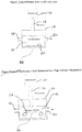
- Fig. 1 there is shown a schematic view of a system that can be used where one of the reactants is utilized as an aqueous solution and the other is a solid.
- a liquid reactant source 10 that can be an aqueous solution of a nitrite salt.
- the liquid nitrite from the source 10 is withdrawn or pumped out by a liquid dispensing means in the form of a controllable micro pump 12 so that the liquid nitrite enters a housing 14 enclosing a reaction chamber 16.
- the housing 14 also has formed therein an inlet 18 for admitting room air or other carrier gas and an outlet 20 for discharging the NO-laden carrier gas from the reaction chamber 16 to deliver that gas to a patient.
- the liquid dispensing means or micro pump 12 can be constructed through a number of different technologies that could be used to dispense nanoliter amounts of liquid.
- micro pump valves which open for a short period of time and allow liquid from a pressurize reservoir to be delivered through a small orifice (0.1 to 0.25 mm diameter) while in the open phase.
- Another technology for the micro pump 12 can be through the use of inkjet style printer heads (piezoelectric or thermal) to deliver the fine droplets required.
- Typical inkjet printer heads have droplet sizes of 10 to 100 picoliters (100 x 10 -12 L) which is substantially smaller than would be required in the practice of the present invention.
- ink jet printer heads can have up to 100 orifices per printhead and can deliver droplets at a rate of up to 12 MHz. Accordingly, by delivering multiple droplets from multiple orifices, the total amount required can be delivered very quickly. For instance, 100 orifices delivering simultaneously 6 droplets/orifice would be needed to deliver the 62 nL in the example above.
- a disk 22 of substrate material, such as polyethylene, has a thin layer of the other reactant, i.e. the reductant, coated on a reaction surface, that is, the upper surface 24 thereof such that the liquid nitrite droplets hit the coating of the reductant on the upper surface 24 of the disc 22 to allow the reaction to take place as has been previously explained, thereby forming NO gas that then passes through the outlet 20 to enter the airway of the patient.
- the disc 22 can be rotated to advance to a new position after each local reaction from a droplet, and the position of the micro pump 12 can move along a linear path from the outside of the disc 22 to the inside to create a spiral thereby using all of the available reactant that is present on the upper surface 24 of the disc 22.
- the reaction is controlled by the rate the reactant liquid is caused to enter into the reaction chamber 16 and contact the solid reactant.
- Fig. 2 there is shown a schematic view of an alternate embodiment where a liquid reactant is contacted with a solid reactant.
- the basic components are the same and have been give the same identification numbers, however, in this embodiment, the reaction takes place on a tape 26 that is movable.
- the tape 26 can be moved to provide another area of the solid reactant coating to receive a subsequent droplet. If the tape 26 is wide, the position of the micro pump 12 can move along a lateral linear path that is at a right angle to the direction of the movement of the tape 26, to use all the available reactant that is present on the upper surface 28 of the tape 26.
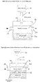
- a liquid reactant source 10 that can be liquid nitrite compound, such as an aqueous solution of sodium nitrite.
- the liquid nitrite from the source 10 is withdrawn or pumped out by a liquid dispensing means in the form of a controllable micro pump 12, so that the liquid nitrite enters a housing 14 enclosing the reaction chamber 16.
- the other reactant i.e. the reductant, is in liquid form and is located in a reservoir 30 formed in the housing 14.
- the droplet of the nitrite thereupon falls from the micro pump 12 down into the liquid reductant, so as to react therewith and form the NO gas that is passed through the outlet 20 to the airway of the patient. Since the supply of the liquid reductant is by means of a reservoir, it will be appreciated that there is no need to move the location of the micro pump 12. Again, the reaction that takes place between the reactants, and therefore the production of NO, is controlled by controlling the rate at which the droplets of nitrite are introduced into the reaction chamber 16 to react with the liquid acid reductant since the reaction will take place only so long as there is nitrite salt present to react.
- Fig. 4 there is an exemplary embodiment of an alternative embodiment to the Fig. 3 embodiment and where there is a roller 32 having an outer surface that is partially disposed below the surface of the liquid reductant such that, as the roller 32 rotates, fresh liquid reductant is continually brought out of the reservoir 30 so as to be positioned to receive a droplet of the liquid nitrite from the micro pump 12.
- the roller 32 can be rotated to bring a fresh supply of the liquid reductant in position to receive the next droplet.
- the outer surface of the roller 32 can be roughened to increase the local surface area.
- Fig. 5 there is shown a schematic view of a system where both of the reactants are in aqueous solution and there is a pair of liquid dispensing means.
- a nitrite source 34 and a reductant source 36 both of which have their respective liquids removed therefrom by means of micro pumps 38 and 40.
- the respective droplets are then dispensed onto a reaction surface 42 within the reaction chamber 16.
- the movement system can move either the micro pumps 38 and 40 or the reaction surface 42, or both, to make sure there is a proper alignment of the respective droplets to provide the reaction for producing NO.
- the reaction surface 42 can be a rotating disc, a rotating cylinder or a tape advancement mechanism, each of which are described with respect to Figs. 2-4 , and which can be used to align or register the location of the second deposited droplet with the first deposited droplet.
- the surface of the index substrate can be heated to increase the reaction rate and to cause any residual water to be evaporated.
- the remaining reaction side product e.g. sodium ascorbate
- the remaining reaction side product e.g. sodium ascorbate
- the tape 26 is advanced to its next index position, it automatically removes the side product compound from the liquid dispensing means and stores it on the tape 26.
- the roller 32 of the Fig. 4 embodiment rotates to bring a new supply of the liquid reactant to the upper area, that movement also removes the side product compound from the reaction surface.
- Fig. 5 where both of the liquid reactants are dispensed in a controlled manner, some way of removing the side products must be added.
- This holding chamber can also have neutralizing compounds, such as activated charcoal, to stop any further reaction and to keep any cross-over from the holding chamber getting back into the reaction chamber.
- Another way of achieving this is to have the holding chamber at a lower pressure by pumping gas out of it and passing it through a scrubber before exhausting to atmosphere.
- the NO 2 can be removed downstream of the chamber with the addition of an NO 2 scrubber.
- Materials that can be used to remove NO 2 are sulfurous polymer (see EU 0763500A2 ) or soda lime.
- the present invention can administer the NO generated to the patient.
- the simplest means is for the patient to breath in through the reaction chamber so the NO generated is taken directly into the patients lung like an inhaler.
- the patient would simply press a button to generate the NO and then inhale the gas mixture directly from the reaction chamber.
- the device could have sensor means to detect when the patient took a breath and that would signal the device to generate the NO. This detection of the patient's inspiration could be either by pressure drop or flow indication.
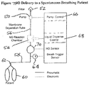
- a gas delivery system for a spontaneously breathing patient that has a pump 50 that draws in room air through a filter 52 and pumps that air through the reaction chamber 54.
- a membrane separation tube 56 located upstream of the reaction chamber 54 to remove some oxygen in the manner and for the purpose as explained with respect to the membrane separation tube 44 of Fig. 6 .
- the pump 50 is shown located upstream of the reaction chamber 54, it could alternatively be located downstream of the reaction chamber 54 and draw the air through the reaction chamber 54.
- a conduit 58 delivers the NO-containing gas from the reaction chamber 54 to the patient 60 where it can be administered to the patient 60 by means of a patient device such as a nasal cannula 62.
- a nasal cannula is designed to provide supplemental air flow to the patient and therefore, does not form a seal with the patient's airway, so additional room air is taken in as the patient breathes.
- the conduit 58 could also contain a breath trigger sensor 64 to act as a breath detector to determine when the patient was breathing in and, therefore, when to generate the NO.
- the pump 50 could operate either continuously or only when NO was being generated and hence work in a pulse mode to deliver gas flow through the reaction chamber 54 where the stream of gas picks up the NO and carries it through the nasal cannula 62 and thence to the patient 60.
- a pump control 66 that controls the operation of the pump 50.
- a liquid dispense control 68 that controls the reaction occurring within the reaction chamber 54 as has been previously explained so that the amount of NO generated is controlled to provide the desired amount of NO to the patient 60.
- FIG. 8 there is a schematic view of a NO delivery system for use when the patient is being mechanically ventilated.
- a pump 50 that draws in room air through a filter 52 and pumps that air through the reaction chamber 54 with an optional membrane separation tube 56 located upstream of the reaction chamber 54.
- Conduit 58 delivers the NO containing gas from the reaction chamber 54 where it can be administered to the patient 60.
- This conduit 58 could also contain a breath trigger sensor 64 that senses the breathing of a patient and a pump control 66 that can be utilized as described with respect to Fig. 7 .
- the patient device can be a endrotracheal tube or face mask 72 that interjects the NO-containing gas along with the gas administered by ventilator 74 through the inspiratory limb 76.
- the expired gases from the patient 60 are carried from the patient 60 through the expiratory limb 78 back to the ventilator 74.
- a NO sensor 70 is present to determine the concentration of NO in the stream of gas delivered to the patient 60.
- other gas delivery systems can be used in place of a ventilator, such as a breathing bag filled with gas from a flowmeter, or a constant positive airway pressure (CPAP) where the gas flow is from a blower.
- CPAP constant positive airway pressure
- reaction chamber design which use different sources of reaction compounds (both solid and liquid) to generate NO.
- the test configuration in each case was as described in Fig. 9 and which includes a reaction chamber 80 where the reaction takes place in generating the NO.
- a pump 82 continuously pulls in room air via an inlet 84 so as to pass through the reaction chamber 82 where the reaction takes place in the generation of NO.
- a flow sensor 86 is located downstream of the reaction chamber 80 that measures the total gas flow and a chemiluminescent analyzer 88 carries out the analysis of the NO in the gas passing from the outlet 90.
- the chemiluminescent analyzer 88 has a response time of 60 msec, so it is fast enough to give a real time measurement although there is a 2 second lag in processing time before the measurement is available to a chart recorder.
- liquid dispensing means was a small pressurized (5psi) liquid reservoir that fed a VHS micro dispensing valve (The Lee Company) using a spike voltage control circuit.
- the average amount of liquid dispensed was determined by gravimetric measurement over 45 minutes when pulsing once per second.
- the first example was carried out using the apparatus of Fig. 3 .
- Aqueous sodium nitrite (1 molar solution) was dispensed directly into a chamber with a reservoir of liquid reductant.
- the reductant was 1 molar solution of ascorbic acid with 1 molar maleic acid added.
- the flow through the reaction chamber (Qc) was 0.5 L/min of air and the micro pump delivered 48 nL per pulse every second.
- Average concentration of NO from the reaction chamber was approximately 123 ppm as shown in Fig. 10 .
- N NO C NO .10 ⁇ 6 .4.16 ⁇ 10 ⁇ 5 .
- the response time of the reaction was a lot quicker with distinct pulses of NO corresponding to each droplet of sodium nitrite solution being delivered.
- the total reaction time for each pulse was less than 1 second.
- the peak NO concentration was approximately 300 ppm, with an average concentration over a 1 second period of around 117 ppm. This corresponds to an output of about 40 nmoles of NO, but as can be seen, in a substantially reduced reaction time.
- both the nitrite and the reductant were dispensed with micro dispensing valves that were configured to deposit the liquid droplets at the same location at the bottom of the reaction chamber.
- the apparatus was as described in Fig. 5 .
- the sodium nitrite was a 2 molar solution and the reductant was 1.5 molar solution of ascorbic acid with 0.5 molar maleic acid.
- the micro pump delivered 42 nL per pulse of sodium nitrate and the second pump delivered 54 nL per pulse of reductant both were pulsed simultaneously every second.
- the gas flow through the reaction chamber was 0.360 L/min of air.
- liquid sodium nitrite (6 molar solution) was dispensed onto a solid reductant that had been formed by allowing a solution that was 1 molar in ascorbic acid and 1 molar in maleic acid to evaporate onto a polyethylene disc thereby forming a crystallized thin film of reductant.
- the gas flow through the chamber was 5 L/min of air.
- the micro pump delivered 43 nL per pulse of the 6 molar sodium nitrate.
- the NO output from the reaction chamber resulted in a peak concentration of 216 ppm NO spike which lasted about 1 second and corresponded to an average concentration of 73 ppm over the 1 second period.
- a gas flow 5 l/min air this corresponded to a calculated NO delivery per pulse of 252 nmoles / pulse which is very close to the predicted 43 nL x 6 molar concentration which equals 258 nmoles of sodium nitrite delivered.
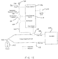
- FIG. 12 there is a schematic view of a NO delivery system for use wherein the system has the capability of setting the NO concentration to be administrated to a patient.
- a pump 92 that draws in room air through a filter 94 and pumps that air through the reaction chamber 96 with an optional membrane separation tube 98 located upstream of the reaction chamber 96.
- Conduit 100 delivers the NO-containing gas from the reaction chamber 96 where it can be administered to the patient 102.
- a ventilator 106 breathes the patient via an inspiratory limb 108 by means of an endotracheal tube or face mask 110 while the exhaled gases from the patient are returned to the ventilator 106 via an expiratory limb 112.
- liquid dispense control 114 that controls the reaction occurring within the reaction chamber 96 so that the amount of NO generated in the NO reaction chamber 96 is controlled and a pump control 116 to control the pump 92.
- a flow sensor 118 that is located in the inspiratory limb 108 to measure the flow of the breathing air that is being provided by the ventilator 106 to the patient 102 through that inspiratory limb 108.
- an input device 120 is provided so that the user can enter the desired concentration of NO to be administered to the patient 102. Since the flow to the patient 102 is known from the flow sensor 118, the liquid dispense control 114 can control the NO being generated in the NO reaction chamber to combine with that known flow to deliver to NO concentration set by the user by the input device 120.
Landscapes
- Health & Medical Sciences (AREA)
- Life Sciences & Earth Sciences (AREA)
- Veterinary Medicine (AREA)
- Public Health (AREA)
- General Health & Medical Sciences (AREA)
- Animal Behavior & Ethology (AREA)
- Pulmonology (AREA)
- Engineering & Computer Science (AREA)
- Biomedical Technology (AREA)
- Emergency Medicine (AREA)
- Hematology (AREA)
- Heart & Thoracic Surgery (AREA)
- Anesthesiology (AREA)
- Chemical & Material Sciences (AREA)
- Medicinal Chemistry (AREA)
- Pharmacology & Pharmacy (AREA)
- Inorganic Chemistry (AREA)
- Epidemiology (AREA)
- Chemical Kinetics & Catalysis (AREA)
- Organic Chemistry (AREA)
- General Chemical & Material Sciences (AREA)
- Bioinformatics & Cheminformatics (AREA)
- Nuclear Medicine, Radiotherapy & Molecular Imaging (AREA)
- Pharmaceuticals Containing Other Organic And Inorganic Compounds (AREA)
Description
- This application is a divisional application of
EP07870651.2 - The present invention relates to a system for generating and administering nitric oxide (NO) to a patient, and, more particularly, to a system that generates the NO proximate to and for immediate delivery to the patient.
- The administration of nitric oxide (NO) gas via inhalation for treating patients with pulmonary hypertension is described in
Zapol and Frostell's US patent 5,485,827 "Methods and Devices for Treating Pulmonary Vasoconstriction and Asthma". - At the present, nitric oxide gas is commonly used for the treatment of persistent pulmonary hypertension in the newborn and is indicated for the treatment of term and near-term (>34 weeks) neonates with hypoxic respiratory failure (HRF) associated with clinical or echocardiographic evidence of pulmonary hypertension. In babies with HRF, blood vessels in the lungs constrict, making it difficult for the heart to pump blood through the lungs for oxygenation. Nitric oxide is a pulmonary vasodilator, which relaxes the blood vessels of the lungs in newborns whose heart and lungs could not otherwise carry enough oxygenated blood to the body tissues.
- There are also other clinical applications in which NO is used to treat surface infections on the skin of a patient as described in
US patent 6,432,077 . -
US patent 5,670,127 "Process for the Manufacture of Nitric Oxide" (Lien-Lung Sheu) describes a method for producing nitric oxide, NO, for medical use by reacting aqueous nitric acid with gaseous sulfur dioxide in a gas-liquid contact reactor to produce 100% NO gas. It is important to note that all of the reactants used in this method are hazardous to handle and, accordingly, the process has to be strictly controlled. The NO produced by this method, which is close to 100%, is blended with an inert diluent, preferably nitrogen, to produce a pressurized gas source in a safe and useable concentration, currently in the range of 100 to 800 ppm of NO. Because this method uses cylinder concentrations in the parts per million (ppm) level it requires the use of large pressurized cylinders (approximately 175 mm diameter and 910 mm high with a wetted volume of 16 L and a weight of 18 Kg), which are bulky, heavy, and provide logistical problems and safety requirements associated with the handling of large pressurized gas cylinders. The cylinders are pressurized to 150 Bar and hold approximately 2000 L of useable gas. However, at a concentration of 800 ppm NO gas, the total drug quantity is 0.066 moles which weighs only 2 gms. Hence, it can be seen that the drug packaging represents 9,000 times the weight of the drug contained therein. - Nitric oxide readily combines with oxygen (O2) to form nitrogen dioxide (NO2), a known toxic gas, so it is very important that the gas cylinder does not become contaminated with oxygen. It is for this reason that the diluent gas used in the cylinders is one that is inert to, i.e. will not oxidize, nitric oxide. While a number of such inert gases are known, it is preferred to utilize nitrogen, N2, primarily on the basis of cost.
- The delivery apparatus for dispensing gaseous NO has to deliver the NO source gas into the patient's respirable gas to give a concentration in the range of 1-80 ppm to the patient's lung in a precise and controllable manner. It also has to deliver it in a manner that minimizes the formation of NO2. The parameters that are relevant to the formation of NO2 are the square of the NO concentration, the O2 concentration and the time for the reaction between them to take place. The O2 concentration is not normally controllable by the NO delivery device and the source gas is at a fixed concentration, therefore, the time for the reaction to take place is the only variable.
- Apparatus for the delivery of nitric oxide (NO) from a gas cylinder has to not only precisely deliver the correct dose of NO to the patient, but also to minimize the time from delivery to when the patient breathes in the gas to prevent the formation of NO2 at unsafe levels. An example of a bedside NO delivery device that achieves these two functions is described in U.S. Patent
US 5,558,083 which shows how a constant concentration of NO can be delivered to a patient who is on a gas delivery system such as a ventilator. Smaller ambulatory NO delivery devices are described inUS 6,089,229 ,US 6,109,260 ,US 6,125,846 , andUS 6,164,276 , which describe how dosing can be provided in a pulse mode while keeping NO2 levels at an acceptably low level. While these pulse devices allow a compact and low weight delivery device to be made, they still require the bulk and weight of the NO cylinder for NO to be delivered. - Because of the challenges surrounding the current method of producing, distributing and safely administrating nitric oxide from pressurized cylinders to a patient, there have been a number of alternate solutions proposed to generate NO locally and to immediately deliver it to the patient. Some of those alternate solutions include using an electric arc discharge to produce NO from air prior to delivering it to a patient (
US 5,396,882 ): producing NO for inhalation by establishing a coulometric reduction of copper ions in a solution of nitric acid along with purging the chamber with an inert gas (US 5,827,420 ); using a corona discharge to generate NO in a chamber that contains oxygen and nitrogen (EP 0719159 ); using a plasma chemical reaction method while heating the reaction chamber to 400-800°C to obtain high efficiency of NO production (US 6,296,827 ); and using heat to break down an organic nitrogen-containing compound, such as ammonia, to form NO (US 6,758,214 ). - Each of the proposed solutions, however, has certain drawbacks in the generation of NO for direct delivery to the patient rather than having to handle the bulk and weight of pressurized gas cylinders and all of the proposed solutions fail to meet at least one of the requirements for a successful portable and safe NO generation system for the immediate delivery of NO to a patient. These requirements can include (1) compact size for easy handling (<100mm x 150mm x 50mm); (2) low weight for easy portability (<2 Kgs), (3) no toxic compounds or byproducts that would raise safety concerns, (3) any reactants used should be readily available and not have any special storage or handling requirements, (4) low electrical power consumption so that battery operation is possible if necessary, (5) accurate, controllable generation of NO in just the amount needed for the patient and (6) fast generation so NO can be made and delivered to a patient without allowing NO2 to form.
- Accordingly, it would be advantageous to have a device for the local generation of NO for immediate delivery to the patient and which overcomes the drawbacks and difficulties of the prior attempted solutions and which also possesses all of the desirable characteristics of such a system.
- This invention is defined by
claim 1 and describes devices for the local generation of NO for immediate delivery to a patient that is compact, low weight, requires no toxic reactant compounds, uses low electrical power and provides fast and controllable NO generation. A general aspect of the invention is a method for producing nitric oxide (NO) for the immediate delivery to a mammal, i.e. human or animal by bringing together controllable quantities of a nitrite salt, preferably sodium nitrite, and a reductant, preferably at least one of ascorbic acid and maleic acid, in the presence of water in the desired quantities to produce the amount of NO required by the mammal and for the NO to then be immediately delivered to the mammal. Preferably, NO produced in accordance with the present invention is delivered for inhalation by the mammal. By generating the NO within the apparatus immediately prior to delivering it to the mammal, the time for NO2 formation is kept to a minimum. These and other features and advantages of the present invention will become more readily apparent during the following detailed description taken in conjunction with the drawings herein. -
-
Fig. 1 is a schematic view of a device that can be used for carrying out the present invention, -
Fig. 2 is a schematic view of an alternative device that can be used for carrying out the present invention, -
Fig. 3 is a schematic view of another alternative device that can be used for carrying out the present invention, -
Fig. 4 is a schematic view of a still further alternative device that can be used for carrying out the present invention, -
Fig. 5 is a schematic view of yet another alternative device that can be used for carrying out the present invention, -
Fig. 6 is a perspective view of a membrane separation tube usable with the present invention, -
Fig. 7 is a schematic view of a system for using the present invention with a spontaneously breathing patient, -
Fig. 8 is a schematic view of a system for using the present invention with a mechanically ventilated patient, -
Fig. 9 is a schematic view of a test set up for carrying out testing of the present invention, -
Fig. 10 is an illustration of the test results for NO concentrations for Example 1 using the present invention, -
Fig. 11 is an illustration of the test results for NO concentrations for another Example of a use of the invention, and -
Fig. 12 is a schematic view of a further system for use of the present invention with a NO concentration setting capability. - The present invention uses a nitrite and a reductant in the presence of water to generate NO in gaseous form. In an exemplary embodiment, the nitrite source is sodium nitrite and the reductant is at least one of ascorbic acid and maleic acid, preferably ascorbic acid. The use of these exemplary reactants assures that the materials used to produce the NO are both non-toxic; that is, ascorbic acid is Vitamin C and sodium nitrite is used in curing meats, such as ham, and the like. Therefore, the reactant compounds can be used in proximity to the patient without the danger of toxic materials passing downstream to ultimately reach the patient. As used herein, the term "patient" refers to a human or an animal, preferably the former. In addition, all the reactant compounds are soluble in water, therefore, solutions containing equimolar quantities thereof can readily be prepared. The reaction that produces NO when generated by sodium nitrite and ascorbic acid in accordance with the present invention can be illustrated by
Equation 1
Equation 1 are widely used in the food industry and are non-toxic in the quantities contemplated herein as described above. - One embodiment of the invention is an apparatus that uses an aqueous solution of sodium nitrite that is deposited as liquid droplets in a controlled amount onto an molar excess of ascorbic acid (in solid form or as an aqueous solution). Preferably, very fine droplets are utilized, thus enabling the reaction to proceed quickly and the NO thus-formed available for inhalation or application.
- The amount of NO provided from the reaction is governed by controlling a precise amount of liquid to be brought into contact with the other reactant or reactants. The liquid being dispensed into the reaction chamber is preferably aqueous solutions of the nitrite and/or the reductant. If both the nitrite and the reductant are in a solid state on a substrate, the liquid dispensed to initiate and control the reaction will be water.
- The aqueous solutions utilized to generate NO in accordance with the present invention may contain different molar strengths of sodium nitrite with the size of the liquid reservoir required varying inversely with the molar concentration. For instance, utilizing a 6 molar aqueous solution of sodium nitrite, the amount of solution that would produce the same number of moles of NO as are contained in the 16 L cylinder described above would be just 12 mL and weigh only 12.4 grams. Given a plastic package/housing for the solution (similar to an inkjet printer cartridge), the size would be approximately 30mm x 45mm x 45 mm and weigh around 20 gms, or a total weight of 33 grams. As can be seen compared with the gas cylinder for NO, this gives significant improvement with regard to the drug package size and weight.
- To determine the amount of liquid to be dispensed, it is necessary to quantify the amount of NO required by a patient. The typical range of NO concentration being inhaled by a patient to reduce pulmonary hypertension is 5 to 80 ppm of NO. A typical alveolar volume per patient breath is around 300 to 400 mL at rest. The amount of NO required per breath can therefore be calculated from equation 2.

- N is the number of moles of the gas (mole)
- P is the absolute pressure of the gas (joule/m3)
- V is the volume of the particular gas (m3)
- Ru is the universal gas constant, 8.315 (joule/(gmole. °K)
- T is the absolute temperature (°K)
- Assuming atmospheric pressure (101,315 joule/m3) and 20 °C (293 °K) as the temperature and expressing the volume in mL (x10-6 m3), equation (2) reduces to:

- Equation (3) can be used to calculate the number of moles of NO gas to be delivered to a patient's alveolar volume for a specified concentration by using equation (4).

CNO is the concentration of NO (ppm) Va is the alveolar volume (mL) - For example if the NO concentration required is 5 ppm and the alveolar volume is 300 mL, the amount of NO in moles to be delivered to the patients alveoli per breath would be;
NNO = 5x10⁻⁶ . 4.16x10⁻⁵. 300 = 250x10-9 moles or 62 nmoles. - The molecular weight of sodium nitrite is 69. Hence, a one molar solution contains 69 grams of sodium nitrite per liter. Assuming the reaction described above is 100% efficient and all of the NO produced from the nitrite is in gaseous form, one nmole of NO gas will be produced for every nL of a one molar solution of sodium nitrite.
- The quantity of liquid needed can be reduced by increasing the strength of the solution. For example, if a 2 molar solution were used, then the amount of liquid needed would be reduced by 50 percent. The amount of liquid can be produced as one droplet of exactly the right size or multiple droplets of a smaller size which add up to the amount needed.
- Therefore, it is apparent that it is possible in accordance with the present invention to accurately control the formation of the NO in order to treat the individual patient with specific regard to the desired concentration of the NO to be delivered and the alveolar volume of the patient.
- The bringing together of the two reacting compounds can be achieved in a number of ways. Preferably, a reactant in aqueous solution can be delivered by a suitable liquid dispensing means to the other reactant, which may be in liquid or solid form. In another embodiment, both the nitrite salt and the reductant are in solid form on a substrate and controlled amounts of water are dispensed onto the substrate to allow a controlled amount of the reactants to react thereby generating a controlled amount of NO.
- Turning to
Fig. 1 , there is shown a schematic view of a system that can be used where one of the reactants is utilized as an aqueous solution and the other is a solid. In the exemplary embodiment ofFig. 1 , there can be seen aliquid reactant source 10 that can be an aqueous solution of a nitrite salt. The liquid nitrite from thesource 10 is withdrawn or pumped out by a liquid dispensing means in the form of a controllablemicro pump 12 so that the liquid nitrite enters ahousing 14 enclosing areaction chamber 16. Thehousing 14 also has formed therein aninlet 18 for admitting room air or other carrier gas and anoutlet 20 for discharging the NO-laden carrier gas from thereaction chamber 16 to deliver that gas to a patient. The liquid dispensing means ormicro pump 12 can be constructed through a number of different technologies that could be used to dispense nanoliter amounts of liquid. - One possible technology can involve individual micro pump valves which open for a short period of time and allow liquid from a pressurize reservoir to be delivered through a small orifice (0.1 to 0.25 mm diameter) while in the open phase. Another technology for the
micro pump 12 can be through the use of inkjet style printer heads (piezoelectric or thermal) to deliver the fine droplets required. Typical inkjet printer heads have droplet sizes of 10 to 100 picoliters (100 x 10-12 L) which is substantially smaller than would be required in the practice of the present invention. However, such ink jet printer heads can have up to 100 orifices per printhead and can deliver droplets at a rate of up to 12 MHz. Accordingly, by delivering multiple droplets from multiple orifices, the total amount required can be delivered very quickly. For instance, 100 orifices delivering simultaneously 6 droplets/orifice would be needed to deliver the 62 nL in the example above. - A disk 22 of substrate material, such as polyethylene, has a thin layer of the other reactant, i.e. the reductant, coated on a reaction surface, that is, the
upper surface 24 thereof such that the liquid nitrite droplets hit the coating of the reductant on theupper surface 24 of the disc 22 to allow the reaction to take place as has been previously explained, thereby forming NO gas that then passes through theoutlet 20 to enter the airway of the patient. In order to continue the process, the disc 22 can be rotated to advance to a new position after each local reaction from a droplet, and the position of themicro pump 12 can move along a linear path from the outside of the disc 22 to the inside to create a spiral thereby using all of the available reactant that is present on theupper surface 24 of the disc 22. As can be seen, the reaction is controlled by the rate the reactant liquid is caused to enter into thereaction chamber 16 and contact the solid reactant. - In
Fig. 2 there is shown a schematic view of an alternate embodiment where a liquid reactant is contacted with a solid reactant. In the embodiment shown inFig. 2 , the basic components are the same and have been give the same identification numbers, however, in this embodiment, the reaction takes place on atape 26 that is movable. As such, as each droplet falls from themicro pump 12, it hits the thin layer of the other reactant that is coated to theupper surface 28 of thetape 26 where the reaction takes place. After each droplet reacts, thetape 26 can be moved to provide another area of the solid reactant coating to receive a subsequent droplet. If thetape 26 is wide, the position of themicro pump 12 can move along a lateral linear path that is at a right angle to the direction of the movement of thetape 26, to use all the available reactant that is present on theupper surface 28 of thetape 26. - Turning now to
Fig. 3 , there is shown a schematic view of a system wherein both of the reactants are present in liquid form with, again, only a single liquid dispensing means being utilized. Thus, inFig. 3 , there can be seen aliquid reactant source 10 that can be liquid nitrite compound, such as an aqueous solution of sodium nitrite. Again, the liquid nitrite from thesource 10 is withdrawn or pumped out by a liquid dispensing means in the form of a controllablemicro pump 12, so that the liquid nitrite enters ahousing 14 enclosing thereaction chamber 16. In this embodiment, however, the other reactant, i.e. the reductant, is in liquid form and is located in areservoir 30 formed in thehousing 14. - The droplet of the nitrite thereupon falls from the
micro pump 12 down into the liquid reductant, so as to react therewith and form the NO gas that is passed through theoutlet 20 to the airway of the patient. Since the supply of the liquid reductant is by means of a reservoir, it will be appreciated that there is no need to move the location of themicro pump 12. Again, the reaction that takes place between the reactants, and therefore the production of NO, is controlled by controlling the rate at which the droplets of nitrite are introduced into thereaction chamber 16 to react with the liquid acid reductant since the reaction will take place only so long as there is nitrite salt present to react. - Turning next to
Fig. 4 , there is an exemplary embodiment of an alternative embodiment to theFig. 3 embodiment and where there is aroller 32 having an outer surface that is partially disposed below the surface of the liquid reductant such that, as theroller 32 rotates, fresh liquid reductant is continually brought out of thereservoir 30 so as to be positioned to receive a droplet of the liquid nitrite from themicro pump 12. As such, as a droplet of the liquid nitrite hits the upper area of the outer surface of theroller 32 to react with the liquid reductant located thereon, theroller 32 can be rotated to bring a fresh supply of the liquid reductant in position to receive the next droplet. To speed up the reaction, the outer surface of theroller 32 can be roughened to increase the local surface area. - Turning to
Fig. 5 , there is shown a schematic view of a system where both of the reactants are in aqueous solution and there is a pair of liquid dispensing means. As can be seen, therefore, there is anitrite source 34 and areductant source 36, both of which have their respective liquids removed therefrom by means ofmicro pumps reaction chamber 16. There is a movement system by which the reaction surface 42 is moved to assure that the two droplets are deposited at the same location on the reaction surface 42 so that the individual droplets of reactants can react with each other. The movement system can move either themicro pumps - As examples of such movement system, the reaction surface 42 can be a rotating disc, a rotating cylinder or a tape advancement mechanism, each of which are described with respect to
Figs. 2-4 , and which can be used to align or register the location of the second deposited droplet with the first deposited droplet. In addition, the surface of the index substrate can be heated to increase the reaction rate and to cause any residual water to be evaporated. - In any of the foregoing devices or systems, after the NO has been generated, the remaining reaction side product, e.g. sodium ascorbate, has to be removed from the liquid dispensing means so as to not interfere with following reactions. Some of the solutions described above have inherent means in the design to do this; for example, in the
Fig. 2 embodiment, as thetape 26 is advanced to its next index position, it automatically removes the side product compound from the liquid dispensing means and stores it on thetape 26. Similarly, as theroller 32 of theFig. 4 embodiment rotates to bring a new supply of the liquid reactant to the upper area, that movement also removes the side product compound from the reaction surface. - However in the embodiment of
Fig. 5 , where both of the liquid reactants are dispensed in a controlled manner, some way of removing the side products must be added. This could be a rotating cylinder that is heated to dry the side product into a solid form where it can be scraped off into a holding chamber below the cylinder. This holding chamber can also have neutralizing compounds, such as activated charcoal, to stop any further reaction and to keep any cross-over from the holding chamber getting back into the reaction chamber. Another way of achieving this is to have the holding chamber at a lower pressure by pumping gas out of it and passing it through a scrubber before exhausting to atmosphere. - As stated, there can be a problem with the build up of NO2 levels since that compound is toxic and therefore must be prevented from being generated and administered with the NO to a patient. To that end, a number of solutions can be employed. One such solution is to construct the reaction chamber to be extremely small so as to reduce the washout time and be designed with no areas that can allow stagnant gas to accumulate and cause NO2 to form.
- Another solution is to provide the gas flow through the reaction chamber to be low in oxygen in order to reduce the NO2 reaction rate. This can be achieved with membrane separation technology (
Figure 6 ) which preferentially allows oxygen and water vapor to pass out of the gas stream prior to the reaction chamber. As can be seen inFig. 6 , therefore, there is amembrane separation tube 44 though which the gas passes to be fed into the NO generating device of the present invention. Thus, as the air is moved from theinlet 46 to theoutlet 48 ofmembrane separation tube 44, the water vapor and oxygen, being "fast gases", quickly permeate through the wall of themembrane separation tube 44 and allow the nitrogen to pass through the bore of the membrane to be supplied for the NO reaction of the present invention. - As a further solution, the NO2 can be removed downstream of the chamber with the addition of an NO2 scrubber. Materials that can be used to remove NO2 are sulfurous polymer (see
EU 0763500A2 - There are a number of systems by which the present invention can administer the NO generated to the patient. The simplest means is for the patient to breath in through the reaction chamber so the NO generated is taken directly into the patients lung like an inhaler. The patient would simply press a button to generate the NO and then inhale the gas mixture directly from the reaction chamber.
- Rather than have the patient press a button, the device could have sensor means to detect when the patient took a breath and that would signal the device to generate the NO. This detection of the patient's inspiration could be either by pressure drop or flow indication.
- Instead of a simple inhaler with the reaction chamber proximal to the patient, there is shown, in
Fig. 7 , a gas delivery system for a spontaneously breathing patient that has apump 50 that draws in room air through afilter 52 and pumps that air through thereaction chamber 54. There may also be amembrane separation tube 56 located upstream of thereaction chamber 54 to remove some oxygen in the manner and for the purpose as explained with respect to themembrane separation tube 44 ofFig. 6 . It should be noted that while thepump 50 is shown located upstream of thereaction chamber 54, it could alternatively be located downstream of thereaction chamber 54 and draw the air through thereaction chamber 54. - A
conduit 58 delivers the NO-containing gas from thereaction chamber 54 to the patient 60 where it can be administered to thepatient 60 by means of a patient device such as a nasal cannula 62. A nasal cannula is designed to provide supplemental air flow to the patient and therefore, does not form a seal with the patient's airway, so additional room air is taken in as the patient breathes. Theconduit 58 could also contain abreath trigger sensor 64 to act as a breath detector to determine when the patient was breathing in and, therefore, when to generate the NO. Thepump 50 could operate either continuously or only when NO was being generated and hence work in a pulse mode to deliver gas flow through thereaction chamber 54 where the stream of gas picks up the NO and carries it through the nasal cannula 62 and thence to thepatient 60. As such, there may be apump control 66 that controls the operation of thepump 50. In addition, there is a liquid dispensecontrol 68 that controls the reaction occurring within thereaction chamber 54 as has been previously explained so that the amount of NO generated is controlled to provide the desired amount of NO to thepatient 60. As also can be seen, there is aNO sensor 70 in theconduit 58 to determine the concentration of NO leaving thereaction chamber 54. - Turning next to
Fig. 8 , there is a schematic view of a NO delivery system for use when the patient is being mechanically ventilated. As can be seen inFig. 8 , there is, again, apump 50 that draws in room air through afilter 52 and pumps that air through thereaction chamber 54 with an optionalmembrane separation tube 56 located upstream of thereaction chamber 54.Conduit 58 delivers the NO containing gas from thereaction chamber 54 where it can be administered to thepatient 60. Thisconduit 58 could also contain abreath trigger sensor 64 that senses the breathing of a patient and apump control 66 that can be utilized as described with respect toFig. 7 . There is also a liquid dispensecontrol 68 that controls the reaction occurring within thereaction chamber 54 as has been previously explained so that the amount of NO generated is controlled to provide the desired concentration of NO to thepatient 60. In this embodiment, however, instead of a nasal cannula, the patient device can be a endrotracheal tube or face mask 72 that interjects the NO-containing gas along with the gas administered byventilator 74 through theinspiratory limb 76. The expired gases from the patient 60 are carried from the patient 60 through theexpiratory limb 78 back to theventilator 74. As before, aNO sensor 70 is present to determine the concentration of NO in the stream of gas delivered to thepatient 60. As will be appreciated, other gas delivery systems can be used in place of a ventilator, such as a breathing bag filled with gas from a flowmeter, or a constant positive airway pressure (CPAP) where the gas flow is from a blower. - The following examples describe different configurations of reaction chamber design which use different sources of reaction compounds (both solid and liquid) to generate NO. The test configuration in each case was as described in
Fig. 9 and which includes areaction chamber 80 where the reaction takes place in generating the NO. Apump 82 continuously pulls in room air via aninlet 84 so as to pass through thereaction chamber 82 where the reaction takes place in the generation of NO. Aflow sensor 86 is located downstream of thereaction chamber 80 that measures the total gas flow and achemiluminescent analyzer 88 carries out the analysis of the NO in the gas passing from theoutlet 90. Thechemiluminescent analyzer 88 has a response time of 60 msec, so it is fast enough to give a real time measurement although there is a 2 second lag in processing time before the measurement is available to a chart recorder. - In each case the liquid dispensing means was a small pressurized (5psi) liquid reservoir that fed a VHS micro dispensing valve (The Lee Company) using a spike voltage control circuit. The average amount of liquid dispensed was determined by gravimetric measurement over 45 minutes when pulsing once per second.
- The first example was carried out using the apparatus of
Fig. 3 . Aqueous sodium nitrite (1 molar solution) was dispensed directly into a chamber with a reservoir of liquid reductant. The reductant was 1 molar solution of ascorbic acid with 1 molar maleic acid added. The flow through the reaction chamber (Qc) was 0.5 L/min of air and the micro pump delivered 48 nL per pulse every second. - Average concentration of NO from the reaction chamber was approximately 123 ppm as shown in
Fig. 10 . - The amount of NO being generated can be calculated using
Equation 4 where Va is the flow per second in mL given by;
- The speed of the reaction wasn't that quick with the NO output not showing distinct pulses but blending into a continuous output. During the test, it was noticeable that the reaction was taking place some distance below the surface of the reductant with bubbles of gas being formed and taking some time to reach the surface. This was likely causing a time lag in the output as the NO gas slowly bubbled out of the reductant solution.
- This next example was carried out with the use of the apparatus of
Fig. 4 having a chamber design where the rotary cylinder was used to bring a layer of reductant to the top of the chamber where the aqueous sodium nitrite (1 molar solution) was dispensed onto it. This design was to reduce the delay associated with bubbles of NO forming below the surface of the reductant as seen in Example 1. The flow through the chamber was 0.5 L/min of air and in this case the micro pump was delivering 42 nL per pulse. After each pulse, the rotary reaction surface was rotated to bring fresh reductant to the dispensing means. The rotary reaction surface was roughed up with 400 grip sand paper to provide better reductant retention. The reaction chamber size was also reduced in this design to again speed up the response time of the NO output - As can be seen on the chart of
Fig. 11 , the response time of the reaction was a lot quicker with distinct pulses of NO corresponding to each droplet of sodium nitrite solution being delivered. The total reaction time for each pulse was less than 1 second. The peak NO concentration was approximately 300 ppm, with an average concentration over a 1 second period of around 117 ppm. This corresponds to an output of about 40 nmoles of NO, but as can be seen, in a substantially reduced reaction time. - In this example, both the nitrite and the reductant were dispensed with micro dispensing valves that were configured to deposit the liquid droplets at the same location at the bottom of the reaction chamber. The apparatus was as described in
Fig. 5 . In this example, the sodium nitrite was a 2 molar solution and the reductant was 1.5 molar solution of ascorbic acid with 0.5 molar maleic acid. The micro pump delivered 42 nL per pulse of sodium nitrate and the second pump delivered 54 nL per pulse of reductant both were pulsed simultaneously every second. The gas flow through the reaction chamber was 0.360 L/min of air. - When the system first started up, the output was peaky as in example 2 but as the liquid built up on the reaction chamber floor the output became more like example 1 with the output having a longer reaction time and an average output of NO being delivered. In the slow steady state condition the average output was 385 ppm NO.
- Based on a gas flow of 0.36 L/min this represents an NO output of 96 nmoles/pulse.
- In this example, carried out using the apparatus of
Fig. 1 , liquid sodium nitrite (6 molar solution) was dispensed onto a solid reductant that had been formed by allowing a solution that was 1 molar in ascorbic acid and 1 molar in maleic acid to evaporate onto a polyethylene disc thereby forming a crystallized thin film of reductant.
The gas flow through the chamber was 5 L/min of air.
The micro pump delivered 43 nL per pulse of the 6 molar sodium nitrate. - The NO output from the reaction chamber resulted in a peak concentration of 216 ppm NO spike which lasted about 1 second and corresponded to an average concentration of 73 ppm over the 1 second period. At a gas flow 5 l/min air this corresponded to a calculated NO delivery per pulse of 252 nmoles / pulse which is very close to the predicted 43 nL x 6 molar concentration which equals 258 nmoles of sodium nitrite delivered.
- Turning lastly to
Fig. 12 , there is a schematic view of a NO delivery system for use wherein the system has the capability of setting the NO concentration to be administrated to a patient. As can be seen inFig. 12 , there is, again, apump 92 that draws in room air through afilter 94 and pumps that air through thereaction chamber 96 with an optionalmembrane separation tube 98 located upstream of thereaction chamber 96.Conduit 100 delivers the NO-containing gas from thereaction chamber 96 where it can be administered to thepatient 102. There is anNO sensor 104 to determine the concentration of NO in the stream of gas delivered to thepatient 102. As with theFig 8 system, aventilator 106 breathes the patient via aninspiratory limb 108 by means of an endotracheal tube or face mask 110 while the exhaled gases from the patient are returned to theventilator 106 via anexpiratory limb 112. - There is also a liquid dispense
control 114 that controls the reaction occurring within thereaction chamber 96 so that the amount of NO generated in theNO reaction chamber 96 is controlled and apump control 116 to control thepump 92. With this embodiment, there is also aflow sensor 118 that is located in theinspiratory limb 108 to measure the flow of the breathing air that is being provided by theventilator 106 to thepatient 102 through thatinspiratory limb 108. - In this embodiment, therefore, an
input device 120 is provided so that the user can enter the desired concentration of NO to be administered to thepatient 102. Since the flow to thepatient 102 is known from theflow sensor 118, the liquid dispensecontrol 114 can control the NO being generated in the NO reaction chamber to combine with that known flow to deliver to NO concentration set by the user by theinput device 120. - Those skilled in the art will readily recognize numerous adaptations and modifications which can be made to the NO generation system and method of generating NO of the present invention which will result in an improved method and system for generating and directly introducing NO into the airway of a patient, yet all of which will fall within the scope of the present invention as defined in the following claims. Accordingly, the invention is to be limited only by the following claims.
Claims (13)
- A device for controlled intermittent or continuous delivery of nitric oxide (NO) to the lung of a mammal, said device comprising:a reaction chamber (16, 54) in fluid communication with the mammal;a system to introduce reactants into the reaction chamber that react therein to form NO;a moveable reaction surface (24, 28) having solid nitrite salt or a reductant disposed thereon;a controllable liquid dispensing system (12) adapted to dispense liquid comprising a dissolved nitrite salt or reductant at a controlled continuous or pulsed rate onto the reaction surface to form NO for delivery to the patient by inhalation;a control system (68) for controlling the reaction between the reactants in the reaction chamber to produce a predetermined quantity of NO for delivery;
a conduit (58) adapted to deliver NO from the reaction chamber (16, 54) to a nasal cannula (62), the conduit including a trigger sensor (64) adapted to act as a breath detector to determine when the patient is breathing in and, therefore, when to generate NO; anda pump (50) adapted to operate only when NO is being generated, the pump further adapted to work in a pulse mode to deliver gas flow through the reaction chamber, wherein a stream of gas picks up the NO and carries it to the nasal cannula. - The device of claim 1, wherein the system to introduce reactants comprises a liquid dispensing system adapted to dispense an aqueous solution of a reactant into the reaction chamber in the form of liquid, said system controlling the reaction by controlling the rate at which the liquid is introduced into the reaction chamber.
- The device of claim 1 or 2, wherein the nitrite salt or reductant is coated to the moveable reaction surface (24, 28).
- The device of claim 3, wherein the system to introduce reactants comprises a liquid dispensing system adapted to dispense an aqueous solution of the other reactant into the reaction chamber in the form of liquid, the control system (68) including means to cause said liquid to be received at differing locations on the solid reactant coated on the reaction surface.
- The device of claim 4, wherein said means comprises a movement system adapted to move the reaction surface (24, 28), wherein moving the reaction surface includes movement by rotation or along a linear path.
- The device of claim 1, wherein the control system (68) dispenses a plurality of reactants into the reaction chamber (54) at a controlled rate.
- The device of any of claims 1-6, wherein the nitrite salt, is sodium nitrite, and the reductant comprises ascorbic acid, maleic acid or a mixture thereof.
- The device of any of claims 1-7 further including a patient device (72) for introducing the nitric oxide generated in the reaction chamber (54) to a patient (60).
- The device of claim 8 further including a pump (50) for drawing in ambient air and forcefully passing the ambient air through the reaction chamber (54) to pick up the nitric oxide generated in the reaction chamber, said pump including a pump controller (66) to control the operation thereof for continuous or intermittent operation.
- The device of claim 9 further including a membrane filter means (56) to reduce the oxygen content of the air drawn into the reaction chamber (54), said filter means being located in fluid communication between the pump (50) and the reaction chamber (54)
- The device of claim 8, further including a ventilator (74) to provide an inspiratory gas to the patient through the patient device such that nitric oxide is introduced into the patient device along with the inspiratory gas from the ventilator
- The device of claim 8, further including means for removing NO2 from the gas provided to the patient.
- The device of claim 11, further including an input device for entering a desired concentration of nitric oxide to be delivered to the patient (60), and a flow sensor (70) to determine the flow of gas being provided by the ventilator (74) wherein the amount of nitric oxide delivered to the patient is based on the desired concentration entered into the input device, said amount being calculated based on a measurement of the patient's alveolar volume and the desired concentration of nitric oxide to be provided to the patient.
Applications Claiming Priority (3)
| Application Number | Priority Date | Filing Date | Title |
|---|---|---|---|
| US11/355,670 US8790715B2 (en) | 2006-02-16 | 2006-02-16 | Method and apparatus for generating nitric oxide for medical use |
| EP07870651.2A EP1984052B1 (en) | 2006-02-16 | 2007-01-25 | Method and apparatus for generating nitric oxide for medical use |
| PCT/US2007/002228 WO2008076136A1 (en) | 2006-02-16 | 2007-01-25 | Method and apparatus for generating nitric oxide for medical use |
Related Parent Applications (2)
| Application Number | Title | Priority Date | Filing Date |
|---|---|---|---|
| EP07870651.2A Division EP1984052B1 (en) | 2006-02-16 | 2007-01-25 | Method and apparatus for generating nitric oxide for medical use |
| EP07870651.2A Division-Into EP1984052B1 (en) | 2006-02-16 | 2007-01-25 | Method and apparatus for generating nitric oxide for medical use |
Publications (2)
| Publication Number | Publication Date |
|---|---|
| EP3311870A1 EP3311870A1 (en) | 2018-04-25 |
| EP3311870B1 true EP3311870B1 (en) | 2019-04-24 |
Family
ID=38368850
Family Applications (2)
| Application Number | Title | Priority Date | Filing Date |
|---|---|---|---|
| EP17194639.5A Active EP3311870B1 (en) | 2006-02-16 | 2007-01-25 | Apparatus for generating nitric oxide for medical use |
| EP07870651.2A Active EP1984052B1 (en) | 2006-02-16 | 2007-01-25 | Method and apparatus for generating nitric oxide for medical use |
Family Applications After (1)
| Application Number | Title | Priority Date | Filing Date |
|---|---|---|---|
| EP07870651.2A Active EP1984052B1 (en) | 2006-02-16 | 2007-01-25 | Method and apparatus for generating nitric oxide for medical use |
Country Status (10)
| Country | Link |
|---|---|
| US (3) | US8790715B2 (en) |
| EP (2) | EP3311870B1 (en) |
| JP (1) | JP2009526606A (en) |
| CN (1) | CN101384292A (en) |
| AU (1) | AU2007334600B2 (en) |
| BR (1) | BRPI0708066A2 (en) |
| CA (1) | CA2640552A1 (en) |
| ES (2) | ES2661458T3 (en) |
| PT (2) | PT3311870T (en) |
| WO (1) | WO2008076136A1 (en) |
Families Citing this family (51)
| Publication number | Priority date | Publication date | Assignee | Title |
|---|---|---|---|---|
| JP5564157B2 (en) * | 2003-07-09 | 2014-07-30 | ザ ガバメント オブ ザ ユナイテッド ステイツ オブ アメリカ アズ リプレゼンテッド バイ ザ セクレタリー オブ ザ デパートメント オブ ヘルス アンド ヒューマン サービシーズ | Use of nitrite for the treatment of cardiovascular conditions |
| US7362274B1 (en) * | 2004-07-09 | 2008-04-22 | Huan-Cheng Lien | Coupled feed-in butterfly shaped left/right hand circularly polarized microstrip antenna |
| WO2006125123A2 (en) * | 2005-05-19 | 2006-11-23 | University Of Cincinnati | Methods for treating bacterial respiratory tract infections in an individual using acidified nitrite |
| US8790715B2 (en) * | 2006-02-16 | 2014-07-29 | Ino Therapeutics Llc | Method and apparatus for generating nitric oxide for medical use |
| KR100738543B1 (en) | 2006-12-15 | 2007-07-12 | (주)원익머트리얼즈 | High Purity Nitric Oxide Purifier for Semiconductor and Purification Method Using the Same |
| US20090196930A1 (en) * | 2007-12-27 | 2009-08-06 | Aires Pharmaceuticals, Inc. | Aerosolized nitrite and nitric oxide -donating compounds and uses thereof |
| WO2009093169A1 (en) * | 2008-01-22 | 2009-07-30 | Koninklijke Philips Electronics N.V. | Device for the topical delivery of nitric oxide to a skin surface |
| US9649467B2 (en) * | 2008-01-31 | 2017-05-16 | Syk Technologies, Llc | Nitric oxide reactor and distributor apparatus and method |
| US8434475B2 (en) * | 2008-01-31 | 2013-05-07 | Genosys, Inc. | Nitric oxide reactor and distributor apparatus and method |
| WO2010033916A1 (en) | 2008-09-22 | 2010-03-25 | Geno Llc | Conversion of nitrogen dioxide (no2) to nitric oxide (no) |
| CN105214193B (en) | 2009-05-27 | 2017-11-17 | 马林克罗特医疗产品知识产权公司 | Indexing medicine accommodation apparatus component and indexing drug delivery system for medicine delivery adjusting means |
| US8613958B2 (en) | 2009-06-22 | 2013-12-24 | Geno Llc | Nitric oxide therapies |
| CA3130908A1 (en) | 2009-06-30 | 2010-12-30 | Mallinckrodt Hospital Products IP Limited | Methods of treating term and near-term neonates having hypoxic respiratory failure associated with clinical or echocardiographic evidence of pulmonary hypertension |
| EP2613839B1 (en) | 2010-09-10 | 2018-12-12 | INO Therapeutics LLC | Compositions, methods and articles concerning pharmaceutical nitric oxide and controlled patient delivery systems thereof |
| US9776161B2 (en) * | 2010-12-03 | 2017-10-03 | Koninklijke Philips N.V. | Method and arrangement for generating nitric oxide |
| CN102556987B (en) * | 2010-12-30 | 2014-12-10 | 佛山市华特气体有限公司 | Method for purifying nitric oxide gas |
| EP3650408A1 (en) | 2011-10-03 | 2020-05-13 | NitricGen, Inc. | Apparatus and method for generating nitric oxide in controlled and accurate amounts |
| MX377688B (en) * | 2012-05-31 | 2025-03-10 | Mallinckrodt Hospital Products Ip Ltd | Methods of administering nitric oxide to arterial or arterialized blood |
| AU2014228152B2 (en) | 2013-03-15 | 2018-07-05 | The General Hospital Corporation | Synthesis of nitric oxide gas for inhalation |
| BR112015022466B1 (en) | 2013-03-15 | 2022-11-08 | The General Hospital Corporation | METHOD AND APPARATUS FOR INSPIRATORY SYNTHESIS OF NITRIC OXIDE |
| US10517817B2 (en) | 2013-05-09 | 2019-12-31 | Syk Technologies, Llc | Deep topical systemic nitric oxide therapy apparatus and method |
| PT4316555T (en) | 2014-05-09 | 2025-10-07 | Mallinckrodt Pharmaceuticals Ireland Ltd | Systems and methods for intelligent gas source management and/or systems and methods for delivery of therapeutic gas and/or enhanced performance verification for therapeutic gas delivery |
| US10525226B2 (en) * | 2014-05-14 | 2020-01-07 | Mallinckrodt Hospital Products IP Limited | Systems and methods for indicating lifetime of an NO2-to-NO reactor cartridge used to deliver NO for inhalation therapy to a patient |
| EP3209359B1 (en) | 2014-10-20 | 2020-07-01 | The General Hospital Corporation | Systems and methods for the synthesis of nitric oxide |
| WO2017132275A1 (en) | 2016-01-27 | 2017-08-03 | Syk Technologies, Llc | Nitric oxide topical application apparatus and methods |
| BR112018069582A2 (en) | 2016-03-25 | 2019-01-22 | Massachusetts Gen Hospital | delivery systems and methods for electrical synthesis of nitric oxide plasma |
| CN106641717A (en) * | 2016-11-03 | 2017-05-10 | 济南市儿童医院 | Automatic gas source distribution method, terminal gas source, central gas source and gas source distribution system |
| MX2020010523A (en) | 2017-02-27 | 2021-02-09 | Third Pole Inc | Systems and methods for generating nitric oxide. |
| CA3054656A1 (en) | 2017-02-27 | 2018-08-30 | Third Pole, Inc. | Systems and methods for generating nitric oxide |
| CN110770163B (en) | 2017-02-27 | 2021-08-31 | 第三极股份有限公司 | System and method for mobile generation of nitric oxide |
| WO2018183811A1 (en) | 2017-03-31 | 2018-10-04 | The General Hospital Corporation | Systems and methods for a cooled nitric oxide generator |
| WO2019175674A2 (en) | 2018-03-13 | 2019-09-19 | Regev Gilly | Nitric oxide releasing compositions |
| EP3837523A4 (en) | 2018-08-14 | 2022-05-11 | SaNOtize Research and Development Corp. | Devices and methods for quantifying nitric oxide |
| CA3116166C (en) * | 2018-10-12 | 2026-02-17 | Sanotize Research And Development Corp. | Gas-evolving compositions and container and delivery systems |
| JP7086209B2 (en) * | 2018-10-25 | 2022-06-17 | 帝人ファーマ株式会社 | Relay administration device and nitric oxide administration system |
| JP2022532654A (en) | 2019-05-15 | 2022-07-15 | サード ポール,インコーポレイテッド | Systems and methods for producing nitric oxide |
| EP3969016A4 (en) | 2019-05-15 | 2023-08-16 | Third Pole, Inc. | NITROGEN MONOXIDE GENERATION ARCHITECTURES |
| JP2022533628A (en) | 2019-05-15 | 2022-07-25 | サード ポール,インコーポレイテッド | Electrodes for nitric oxide generation |
| US11986597B2 (en) | 2019-08-23 | 2024-05-21 | NOTA Laboratories, LLC | Nitric oxide generating systems for inhalation |
| EP4069069A4 (en) | 2020-01-11 | 2024-07-03 | Third Pole, Inc. | SYSTEMS AND METHODS FOR GENERATING NITRIC OXIDE WITH HUMIDITY CONTROL |
| US12459820B2 (en) | 2020-06-11 | 2025-11-04 | J. W. Randolph Miller | Stabilized and NO2-inhibited nitric oxide generating gels for inhaled nitric oxide therapy |
| US20210395905A1 (en) | 2020-06-18 | 2021-12-23 | Third Pole, Inc. | Systems and methods for preventing and treating infections with nitric oxide |
| EP4200003A4 (en) * | 2020-08-20 | 2025-01-01 | The UAB Research Foundation | Generation of nitric oxide and delivery systems |
| US12509349B2 (en) | 2020-10-16 | 2025-12-30 | Third Pole, Inc. | Nitric oxide generation process controls |
| GB202101543D0 (en) * | 2021-02-04 | 2021-03-24 | Thirty Respiratory Ltd | Vaping e-liquid composition and the use thereof |
| EP4405019A4 (en) | 2021-09-23 | 2025-07-16 | Third Pole Inc | SYSTEMS AND METHODS FOR DELIVERING NITRIC OXIDE |
| WO2023201363A2 (en) | 2022-04-14 | 2023-10-19 | Third Pole, Inc. | Delivery of medicinal gas in a liquid medium |
| CN117142445B (en) * | 2022-05-23 | 2026-01-20 | 香港城市大学 | Portable nitric oxide generator, method of use and use in therapy for inhalation of nitric oxide |
| WO2024011526A1 (en) * | 2022-07-14 | 2024-01-18 | Nanjing Novlead Biotechnology Co., Ltd. | Nitric oxide generation systems and methods |
| CN118831254B (en) * | 2023-04-26 | 2025-05-09 | 南京诺令生物科技有限公司 | Integrated NO hair growing device and NO hair growing system |
| GB2644374A (en) | 2024-09-20 | 2026-04-08 | Thirty Holdings Ltd | Compositions and kits for generating nitric oxide |
Family Cites Families (28)
| Publication number | Priority date | Publication date | Assignee | Title |
|---|---|---|---|---|
| DE122007000103I1 (en) | 1990-12-05 | 2008-04-03 | Gen Hospital Corp | Use of NO for the treatment of persistent pulmonary hypertension of the newborn |
| US5396882A (en) | 1992-03-11 | 1995-03-14 | The General Hospital Corporation | Generation of nitric oxide from air for medical uses |
| CA2169859A1 (en) | 1993-09-13 | 1995-03-23 | Niels Jacobsen | Method and means for generating nitric oxide |
| US5558083A (en) | 1993-11-22 | 1996-09-24 | Ohmeda Inc. | Nitric oxide delivery system |
| US5648101A (en) | 1994-11-14 | 1997-07-15 | Tawashi; Rashad | Drug delivery of nitric oxide |
| DE19534248A1 (en) | 1995-09-18 | 1997-03-20 | Hoechst Ag | Process for the production of NO¶2¶-free nitrogen monoxide |
| US5670127A (en) | 1995-09-26 | 1997-09-23 | The Boc Group, Inc. | Process for the manufacture of nitric oxide |
| US5732693A (en) | 1996-10-02 | 1998-03-31 | Ohmeda Inc. | Pause control of nitric oxide therapy |
| PT973443E (en) | 1997-01-17 | 2006-08-31 | Ino Therapeutics Gmbh | COMMANDED GAS SUPPLY SYSTEM |
| US6125846A (en) | 1997-05-16 | 2000-10-03 | Datex-Ohmeda, Inc. | Purge system for nitric oxide administration apparatus |
| US6164276A (en) | 1997-05-16 | 2000-12-26 | Datex-Ohmeda, Inc. | Accurate dose nitric oxide pulse delivery device with monitoring and alarms |
| US5827420A (en) | 1997-07-29 | 1998-10-27 | World Precision Instruments, Inc. | Method and apparatus for the generation of nitric oxide |
| US6109260A (en) | 1998-02-18 | 2000-08-29 | Datex-Ohmeda, Inc. | Nitric oxide administration device with timed pulse |
| US6089229A (en) | 1998-05-26 | 2000-07-18 | Datex-Ohmeda, Inc. | High concentration no pulse delivery device |
| DE19823748C2 (en) | 1998-05-27 | 2000-05-18 | Siemens Ag | Method and device for the plasma chemical production of nitrogen monoxide |
| US6103275A (en) | 1998-06-10 | 2000-08-15 | Nitric Oxide Solutions | Systems and methods for topical treatment with nitric oxide |
| US6758214B2 (en) | 2000-01-28 | 2004-07-06 | Cyterra Corporation | Simple nitric oxide generator for ambulatory and/or bedside inhaled no treatment |
| US6474333B1 (en) | 2000-06-14 | 2002-11-05 | Instrumentarium Corp. | Method for purging a medical fluid administration system |
| US6601580B1 (en) | 2000-06-28 | 2003-08-05 | The General Hospital Corporation | Enhancing therapeutic effectiveness of nitric oxide inhalation |
| US6432077B1 (en) | 2000-12-26 | 2002-08-13 | Sensormedics Corporation | Device and method for treatment of surface infections with nitric oxide |
| US6749834B2 (en) | 2001-06-19 | 2004-06-15 | World Precision Instruments, Inc. | Methods and apparatus for therapeutic treatment of respiratory, cardiac and other pathologies |
| US8066904B2 (en) | 2001-09-05 | 2011-11-29 | Geno Llc | Controlled generation of nitric oxide |
| GB0125222D0 (en) | 2001-10-19 | 2001-12-12 | Barts & London Nhs Trust | Composition for the treatment of microbial infections |
| CA2490392A1 (en) | 2002-06-21 | 2003-12-31 | University Of Pittsburgh Of The Commonwealth System Of Higher Education | Pharmaceutical use of nitric oxide, heme oxygenase-1 and products of heme degradation |
| CA2413834A1 (en) | 2002-12-10 | 2004-06-10 | 1017975 Alberta Limited | Nitric oxide gas generator |
| US7288664B2 (en) * | 2004-03-30 | 2007-10-30 | Bela Kleiner | Reverse Kleiner method for manufacturing nitrogen dioxide, nitric oxide, nitric acid, metallic ascorbates and alkyl ascorbates of vitamin C |
| WO2006023616A2 (en) | 2004-08-18 | 2006-03-02 | Geno Llc | Conversion of nitrogen dioxide (no2) to nitric oxide (no) |
| US8790715B2 (en) * | 2006-02-16 | 2014-07-29 | Ino Therapeutics Llc | Method and apparatus for generating nitric oxide for medical use |
-
2006
- 2006-02-16 US US11/355,670 patent/US8790715B2/en active Active
-
2007
- 2007-01-25 EP EP17194639.5A patent/EP3311870B1/en active Active
- 2007-01-25 JP JP2008555249A patent/JP2009526606A/en active Pending
- 2007-01-25 ES ES07870651.2T patent/ES2661458T3/en active Active
- 2007-01-25 WO PCT/US2007/002228 patent/WO2008076136A1/en not_active Ceased
- 2007-01-25 CN CNA2007800057807A patent/CN101384292A/en active Pending
- 2007-01-25 AU AU2007334600A patent/AU2007334600B2/en not_active Ceased
- 2007-01-25 CA CA002640552A patent/CA2640552A1/en not_active Abandoned
- 2007-01-25 PT PT17194639T patent/PT3311870T/en unknown
- 2007-01-25 BR BRPI0708066-2A patent/BRPI0708066A2/en not_active IP Right Cessation
- 2007-01-25 ES ES17194639T patent/ES2736448T3/en active Active
- 2007-01-25 PT PT78706512T patent/PT1984052T/en unknown
- 2007-01-25 EP EP07870651.2A patent/EP1984052B1/en active Active
-
2014
- 2014-06-18 US US14/307,664 patent/US9278111B2/en not_active Expired - Lifetime
-
2016
- 2016-01-27 US US15/008,048 patent/US10537697B2/en not_active Expired - Lifetime
Non-Patent Citations (1)
| Title |
|---|
| None * |
Also Published As
| Publication number | Publication date |
|---|---|
| US20070190184A1 (en) | 2007-08-16 |
| EP1984052A4 (en) | 2012-03-21 |
| AU2007334600A1 (en) | 2008-06-26 |
| WO2008076136A1 (en) | 2008-06-26 |
| BRPI0708066A2 (en) | 2011-05-17 |
| EP1984052A1 (en) | 2008-10-29 |
| ES2736448T3 (en) | 2019-12-30 |
| US20140363525A1 (en) | 2014-12-11 |
| EP1984052B1 (en) | 2017-12-27 |
| ES2661458T3 (en) | 2018-04-02 |
| CA2640552A1 (en) | 2008-06-26 |
| US9278111B2 (en) | 2016-03-08 |
| AU2007334600B2 (en) | 2010-04-08 |
| PT1984052T (en) | 2018-03-09 |
| CN101384292A (en) | 2009-03-11 |
| EP3311870A1 (en) | 2018-04-25 |
| US8790715B2 (en) | 2014-07-29 |
| US10537697B2 (en) | 2020-01-21 |
| JP2009526606A (en) | 2009-07-23 |
| US20160136376A1 (en) | 2016-05-19 |
| PT3311870T (en) | 2019-07-22 |
Similar Documents
| Publication | Publication Date | Title |
|---|---|---|
| EP1984052B1 (en) | Method and apparatus for generating nitric oxide for medical use | |
| US11975139B2 (en) | Systems and methods for delivering nitric oxide | |
| US20170368275A1 (en) | Nebulizer for infants and respiratory compromised patients | |
| EP3479863A1 (en) | Compositions, methods and articles concerning pharmaceutical nitric oxide and controlled patient delivery systems thereof | |
| US20140127330A1 (en) | Method of mixing gases including nitric oxide | |
| AU747465B2 (en) | Inhalers | |
| EP4599876A1 (en) | Generation of nitric oxide and delivery systems | |
| HK1128134A (en) | Method and apparatus for generating nitric oxide for medical use | |
| AU2023214319A1 (en) | Dual metered inhaler | |
| MX2008009894A (en) | Method and apparatus for generating nitric oxide for medical use | |
| JP2025540206A (en) | Respiratory Therapy Systems |
Legal Events
| Date | Code | Title | Description |
|---|---|---|---|
| PUAI | Public reference made under article 153(3) epc to a published international application that has entered the european phase |
Free format text: ORIGINAL CODE: 0009012 |
|
| STAA | Information on the status of an ep patent application or granted ep patent |
Free format text: STATUS: THE APPLICATION HAS BEEN PUBLISHED |
|
| AC | Divisional application: reference to earlier application |
Ref document number: 1984052 Country of ref document: EP Kind code of ref document: P |
|
| AK | Designated contracting states |
Kind code of ref document: A1 Designated state(s): AT BE BG CH CY CZ DE DK EE ES FI FR GB GR HU IE IS IT LI LT LU LV MC NL PL PT RO SE SI SK TR |
|
| STAA | Information on the status of an ep patent application or granted ep patent |
Free format text: STATUS: REQUEST FOR EXAMINATION WAS MADE |
|
| 17P | Request for examination filed |
Effective date: 20180521 |
|
| RBV | Designated contracting states (corrected) |
Designated state(s): AT BE BG CH CY CZ DE DK EE ES FI FR GB GR HU IE IS IT LI LT LU LV MC NL PL PT RO SE SI SK TR |
|
| GRAP | Despatch of communication of intention to grant a patent |
Free format text: ORIGINAL CODE: EPIDOSNIGR1 |
|
| STAA | Information on the status of an ep patent application or granted ep patent |
Free format text: STATUS: GRANT OF PATENT IS INTENDED |
|
| RIC1 | Information provided on ipc code assigned before grant |
Ipc: A61K 33/00 20060101ALI20180927BHEP Ipc: A61M 16/00 20060101ALN20180927BHEP Ipc: A61M 16/10 20060101AFI20180927BHEP Ipc: C01B 21/24 20060101ALI20180927BHEP |
|
| RIC1 | Information provided on ipc code assigned before grant |
Ipc: C01B 21/24 20060101ALI20181010BHEP Ipc: A61M 16/10 20060101AFI20181010BHEP Ipc: A61K 33/00 20060101ALI20181010BHEP Ipc: A61M 16/00 20060101ALN20181010BHEP |
|
| INTG | Intention to grant announced |
Effective date: 20181031 |
|
| GRAS | Grant fee paid |
Free format text: ORIGINAL CODE: EPIDOSNIGR3 |
|
| GRAA | (expected) grant |
Free format text: ORIGINAL CODE: 0009210 |
|
| STAA | Information on the status of an ep patent application or granted ep patent |
Free format text: STATUS: THE PATENT HAS BEEN GRANTED |
|
| AC | Divisional application: reference to earlier application |
Ref document number: 1984052 Country of ref document: EP Kind code of ref document: P |
|
| AK | Designated contracting states |
Kind code of ref document: B1 Designated state(s): AT BE BG CH CY CZ DE DK EE ES FI FR GB GR HU IE IS IT LI LT LU LV MC NL PL PT RO SE SI SK TR |
|
| RAP1 | Party data changed (applicant data changed or rights of an application transferred) |
Owner name: MALLINCKRODT HOSPITAL PRODUCTS IP LIMITED |
|
| REG | Reference to a national code |
Ref country code: GB Ref legal event code: FG4D |
|
| REG | Reference to a national code |
Ref country code: CH Ref legal event code: EP |
|
| REG | Reference to a national code |
Ref country code: AT Ref legal event code: REF Ref document number: 1123394 Country of ref document: AT Kind code of ref document: T Effective date: 20190515 Ref country code: IE Ref legal event code: FG4D |
|
| REG | Reference to a national code |
Ref country code: DE Ref legal event code: R096 Ref document number: 602007058222 Country of ref document: DE |
|
| REG | Reference to a national code |
Ref country code: PT Ref legal event code: SC4A Ref document number: 3311870 Country of ref document: PT Date of ref document: 20190722 Kind code of ref document: T Free format text: AVAILABILITY OF NATIONAL TRANSLATION Effective date: 20190716 |
|
| REG | Reference to a national code |
Ref country code: NL Ref legal event code: FP |
|
| REG | Reference to a national code |
Ref country code: LT Ref legal event code: MG4D |
|
| REG | Reference to a national code |
Ref country code: CH Ref legal event code: NV Representative=s name: SERVOPATENT GMBH, CH |
|
| PG25 | Lapsed in a contracting state [announced via postgrant information from national office to epo] |
Ref country code: LT Free format text: LAPSE BECAUSE OF FAILURE TO SUBMIT A TRANSLATION OF THE DESCRIPTION OR TO PAY THE FEE WITHIN THE PRESCRIBED TIME-LIMIT Effective date: 20190424 Ref country code: FI Free format text: LAPSE BECAUSE OF FAILURE TO SUBMIT A TRANSLATION OF THE DESCRIPTION OR TO PAY THE FEE WITHIN THE PRESCRIBED TIME-LIMIT Effective date: 20190424 Ref country code: SE Free format text: LAPSE BECAUSE OF FAILURE TO SUBMIT A TRANSLATION OF THE DESCRIPTION OR TO PAY THE FEE WITHIN THE PRESCRIBED TIME-LIMIT Effective date: 20190424 |
|
| PG25 | Lapsed in a contracting state [announced via postgrant information from national office to epo] |
Ref country code: GR Free format text: LAPSE BECAUSE OF FAILURE TO SUBMIT A TRANSLATION OF THE DESCRIPTION OR TO PAY THE FEE WITHIN THE PRESCRIBED TIME-LIMIT Effective date: 20190725 Ref country code: BG Free format text: LAPSE BECAUSE OF FAILURE TO SUBMIT A TRANSLATION OF THE DESCRIPTION OR TO PAY THE FEE WITHIN THE PRESCRIBED TIME-LIMIT Effective date: 20190724 Ref country code: LV Free format text: LAPSE BECAUSE OF FAILURE TO SUBMIT A TRANSLATION OF THE DESCRIPTION OR TO PAY THE FEE WITHIN THE PRESCRIBED TIME-LIMIT Effective date: 20190424 Ref country code: PL Free format text: LAPSE BECAUSE OF FAILURE TO SUBMIT A TRANSLATION OF THE DESCRIPTION OR TO PAY THE FEE WITHIN THE PRESCRIBED TIME-LIMIT Effective date: 20190424 |
|
| REG | Reference to a national code |
Ref country code: AT Ref legal event code: MK05 Ref document number: 1123394 Country of ref document: AT Kind code of ref document: T Effective date: 20190424 |
|
| REG | Reference to a national code |
Ref country code: ES Ref legal event code: FG2A Ref document number: 2736448 Country of ref document: ES Kind code of ref document: T3 Effective date: 20191230 |
|
| PG25 | Lapsed in a contracting state [announced via postgrant information from national office to epo] |
Ref country code: IS Free format text: LAPSE BECAUSE OF FAILURE TO SUBMIT A TRANSLATION OF THE DESCRIPTION OR TO PAY THE FEE WITHIN THE PRESCRIBED TIME-LIMIT Effective date: 20190824 |
|
| REG | Reference to a national code |
Ref country code: DE Ref legal event code: R097 Ref document number: 602007058222 Country of ref document: DE |
|
| PG25 | Lapsed in a contracting state [announced via postgrant information from national office to epo] |
Ref country code: EE Free format text: LAPSE BECAUSE OF FAILURE TO SUBMIT A TRANSLATION OF THE DESCRIPTION OR TO PAY THE FEE WITHIN THE PRESCRIBED TIME-LIMIT Effective date: 20190424 Ref country code: AT Free format text: LAPSE BECAUSE OF FAILURE TO SUBMIT A TRANSLATION OF THE DESCRIPTION OR TO PAY THE FEE WITHIN THE PRESCRIBED TIME-LIMIT Effective date: 20190424 Ref country code: SK Free format text: LAPSE BECAUSE OF FAILURE TO SUBMIT A TRANSLATION OF THE DESCRIPTION OR TO PAY THE FEE WITHIN THE PRESCRIBED TIME-LIMIT Effective date: 20190424 Ref country code: DK Free format text: LAPSE BECAUSE OF FAILURE TO SUBMIT A TRANSLATION OF THE DESCRIPTION OR TO PAY THE FEE WITHIN THE PRESCRIBED TIME-LIMIT Effective date: 20190424 Ref country code: RO Free format text: LAPSE BECAUSE OF FAILURE TO SUBMIT A TRANSLATION OF THE DESCRIPTION OR TO PAY THE FEE WITHIN THE PRESCRIBED TIME-LIMIT Effective date: 20190424 Ref country code: CZ Free format text: LAPSE BECAUSE OF FAILURE TO SUBMIT A TRANSLATION OF THE DESCRIPTION OR TO PAY THE FEE WITHIN THE PRESCRIBED TIME-LIMIT Effective date: 20190424 |
|
| PLBE | No opposition filed within time limit |
Free format text: ORIGINAL CODE: 0009261 |
|
| STAA | Information on the status of an ep patent application or granted ep patent |
Free format text: STATUS: NO OPPOSITION FILED WITHIN TIME LIMIT |
|
| PG25 | Lapsed in a contracting state [announced via postgrant information from national office to epo] |
Ref country code: TR Free format text: LAPSE BECAUSE OF FAILURE TO SUBMIT A TRANSLATION OF THE DESCRIPTION OR TO PAY THE FEE WITHIN THE PRESCRIBED TIME-LIMIT Effective date: 20190424 |
|
| 26N | No opposition filed |
Effective date: 20200127 |
|
| PG25 | Lapsed in a contracting state [announced via postgrant information from national office to epo] |
Ref country code: SI Free format text: LAPSE BECAUSE OF FAILURE TO SUBMIT A TRANSLATION OF THE DESCRIPTION OR TO PAY THE FEE WITHIN THE PRESCRIBED TIME-LIMIT Effective date: 20190424 |
|
| REG | Reference to a national code |
Ref country code: CH Ref legal event code: PCAR Free format text: NEW ADDRESS: WANNERSTRASSE 9/1, 8045 ZUERICH (CH) |
|
| PG25 | Lapsed in a contracting state [announced via postgrant information from national office to epo] |
Ref country code: MC Free format text: LAPSE BECAUSE OF FAILURE TO SUBMIT A TRANSLATION OF THE DESCRIPTION OR TO PAY THE FEE WITHIN THE PRESCRIBED TIME-LIMIT Effective date: 20190424 |
|
| PG25 | Lapsed in a contracting state [announced via postgrant information from national office to epo] |
Ref country code: LU Free format text: LAPSE BECAUSE OF NON-PAYMENT OF DUE FEES Effective date: 20200125 |
|
| PG25 | Lapsed in a contracting state [announced via postgrant information from national office to epo] |
Ref country code: CY Free format text: LAPSE BECAUSE OF FAILURE TO SUBMIT A TRANSLATION OF THE DESCRIPTION OR TO PAY THE FEE WITHIN THE PRESCRIBED TIME-LIMIT Effective date: 20190424 |
|
| REG | Reference to a national code |
Ref country code: CH Ref legal event code: U11 Free format text: ST27 STATUS EVENT CODE: U-0-0-U10-U11 (AS PROVIDED BY THE NATIONAL OFFICE) Effective date: 20260201 |
|
| PGFP | Annual fee paid to national office [announced via postgrant information from national office to epo] |
Ref country code: NL Payment date: 20260126 Year of fee payment: 20 |
|
| PGFP | Annual fee paid to national office [announced via postgrant information from national office to epo] |
Ref country code: GB Payment date: 20260127 Year of fee payment: 20 |
|
| PGFP | Annual fee paid to national office [announced via postgrant information from national office to epo] |
Ref country code: ES Payment date: 20260202 Year of fee payment: 20 |
|
| PGFP | Annual fee paid to national office [announced via postgrant information from national office to epo] |
Ref country code: DE Payment date: 20260128 Year of fee payment: 20 Ref country code: IE Payment date: 20260127 Year of fee payment: 20 |
|
| PGFP | Annual fee paid to national office [announced via postgrant information from national office to epo] |
Ref country code: BE Payment date: 20260127 Year of fee payment: 20 Ref country code: IT Payment date: 20260121 Year of fee payment: 20 |
|
| PGFP | Annual fee paid to national office [announced via postgrant information from national office to epo] |
Ref country code: FR Payment date: 20260126 Year of fee payment: 20 |
|
| PGFP | Annual fee paid to national office [announced via postgrant information from national office to epo] |
Ref country code: CH Payment date: 20260201 Year of fee payment: 20 Ref country code: PT Payment date: 20260108 Year of fee payment: 20 |