EP3311472B1 - Broadband vibrational energy harvesting device combining multiple nonlinearity - Google Patents
Broadband vibrational energy harvesting device combining multiple nonlinearity Download PDFInfo
- Publication number
- EP3311472B1 EP3311472B1 EP16736001.5A EP16736001A EP3311472B1 EP 3311472 B1 EP3311472 B1 EP 3311472B1 EP 16736001 A EP16736001 A EP 16736001A EP 3311472 B1 EP3311472 B1 EP 3311472B1
- Authority
- EP
- European Patent Office
- Prior art keywords
- assembly
- magnetised
- monostable
- clamped
- energy harvesting
- Prior art date
- Legal status (The legal status is an assumption and is not a legal conclusion. Google has not performed a legal analysis and makes no representation as to the accuracy of the status listed.)
- Active
Links
Images




Classifications
-
- H—ELECTRICITY
- H02—GENERATION; CONVERSION OR DISTRIBUTION OF ELECTRIC POWER
- H02K—DYNAMO-ELECTRIC MACHINES
- H02K35/00—Generators with reciprocating, oscillating or vibrating coil system, magnet, armature or other part of the magnetic circuit
- H02K35/02—Generators with reciprocating, oscillating or vibrating coil system, magnet, armature or other part of the magnetic circuit with moving magnets and stationary coil systems
-
- G—PHYSICS
- G01—MEASURING; TESTING
- G01H—MEASUREMENT OF MECHANICAL VIBRATIONS OR ULTRASONIC, SONIC OR INFRASONIC WAVES
- G01H11/00—Measuring mechanical vibrations or ultrasonic, sonic or infrasonic waves by detecting changes in electric or magnetic properties
- G01H11/02—Measuring mechanical vibrations or ultrasonic, sonic or infrasonic waves by detecting changes in electric or magnetic properties by magnetic means, e.g. reluctance
-
- G—PHYSICS
- G01—MEASURING; TESTING
- G01H—MEASUREMENT OF MECHANICAL VIBRATIONS OR ULTRASONIC, SONIC OR INFRASONIC WAVES
- G01H11/00—Measuring mechanical vibrations or ultrasonic, sonic or infrasonic waves by detecting changes in electric or magnetic properties
- G01H11/06—Measuring mechanical vibrations or ultrasonic, sonic or infrasonic waves by detecting changes in electric or magnetic properties by electric means
- G01H11/08—Measuring mechanical vibrations or ultrasonic, sonic or infrasonic waves by detecting changes in electric or magnetic properties by electric means using piezoelectric devices
-
- G—PHYSICS
- G01—MEASURING; TESTING
- G01R—MEASURING ELECTRIC VARIABLES; MEASURING MAGNETIC VARIABLES
- G01R17/00—Measuring arrangements involving comparison with a reference value, e.g. bridge
-
- H—ELECTRICITY
- H02—GENERATION; CONVERSION OR DISTRIBUTION OF ELECTRIC POWER
- H02N—ELECTRIC MACHINES NOT OTHERWISE PROVIDED FOR
- H02N2/00—Electric machines in general using piezoelectric effect, electrostriction or magnetostriction
- H02N2/18—Electric machines in general using piezoelectric effect, electrostriction or magnetostriction producing electrical output from mechanical input, e.g. generators
- H02N2/186—Vibration harvesters
-
- H—ELECTRICITY
- H10—SEMICONDUCTOR DEVICES; ELECTRIC SOLID-STATE DEVICES NOT OTHERWISE PROVIDED FOR
- H10N—ELECTRIC SOLID-STATE DEVICES NOT OTHERWISE PROVIDED FOR
- H10N30/00—Piezoelectric or electrostrictive devices
- H10N30/30—Piezoelectric or electrostrictive devices with mechanical input and electrical output, e.g. functioning as generators or sensors
- H10N30/302—Sensors
-
- H—ELECTRICITY
- H10—SEMICONDUCTOR DEVICES; ELECTRIC SOLID-STATE DEVICES NOT OTHERWISE PROVIDED FOR
- H10N—ELECTRIC SOLID-STATE DEVICES NOT OTHERWISE PROVIDED FOR
- H10N30/00—Piezoelectric or electrostrictive devices
- H10N30/30—Piezoelectric or electrostrictive devices with mechanical input and electrical output, e.g. functioning as generators or sensors
- H10N30/304—Beam type
- H10N30/306—Cantilevers
Definitions
- the present invention relates to a method of harvesting vibration energy and to an energy harvesting device. More particularly, the present invention relates to a wideband vibrational energy harvesting device.
- Wireless sensor networks which find applications in a plethora of human interests and activities, e.g. environmental and structural health monitoring, surveillance, medical sensors for remote diagnosis, wearable electronic devices etc. leading to 'Internet-of-Things' (IoT), can be powered at few to hundreds of microwatts.
- vibrational energy harvesting has emerged in the last decade as the potential alternative of battery, to power such WSNs mainly due to their abundance in nature.
- Basic VEH devices consist of a spring, a seismic mass and a damping element.
- the response of most of the earlier reported VEH systems are linear/resonant in nature i.e. they produce the maximum output at the resonance frequency, but the response drops drastically when frequency shifts slightly. In a practical setting, such change of frequency is often observed.
- wideband mechanisms are essential.
- Nonlinear oscillators have amplitude modulated stiffness, which provides broadband response under external excitation.
- Nonlinear monostable devices based on cantilever stretching (hardening nonlinearity) effects were studied in "Smart Sand-a wide bandwidth vibration energy harvesting platform” (Appl. Phys. Lett., 94:103505 (2009 )) and this configuration also demonstrated bandwidth widening effects. A similar bandwidth widening effect was observed for different structural topologies in " A nonlinear stretching based electromagnetic energy harvester on FR4 for wideband operation” (Smart Mater. Struct. 24:- 015013, 2015 ).
- Erturk et al developed and studied a piezomagnetoelastic device consisting of a ferromagnetic cantilever and piezoceramic laminates for power generation in " A piezo-magneto-elastic structure for broadband vibration energy harvesting” (Applied Physics Letters 94 (254102) (2009) 1-3 ). They studied forced responses at various frequencies and obtained large amplitude periodic responses across a wide range of excitation frequencies.
- US 2012/0068577 A1 disclosed a micro-scale piezoelectric nonlinear energy harvesting device, in which a central mass is suspended by four tethers with piezoelectric materials. The vertical motion of the suspended mass would produce stress in the tethers, and thereby generate electricity in the piezoelectric material, wherein the beams supporting the mass produce stretching-based nonlinearity.
- WO 2014/116794 A1 described a meandered piezoelectric cantilever based energy harvester for very low frequency ( ⁇ 1 Hz) operation, in which a magnetic component at the free end of the beam allows nonlinear vibration, and wide operational frequency range.
- This device however employed piezoelectric transduction, which requires load matching circuitry.
- Ferrari et al investigated a system similar to that described in " Improved Energy Harvesting from Wideband Vibrations by Nonlinear Piezoelectric Converters, Sensors and Actuators” (A: Physical, 162 (2010), 425-431 ), wherein bistability was introduced into the system by oppositely positioned permanent magnets.
- Monostable and bistable systems therefore have an inherent capability to improve the off- resonance performance compared to a resonant system, demonstrably wider frequency bandwidth under harmonic and random excitations compared to the corresponding linear vibrational energy harvesters (VEHs).
- VHs linear vibrational energy harvesters
- bistable systems exhibit wideband response under random vibrations, it was observed that they could generate appreciable energy at rather high accelerations, when the oscillator could overcome the potential barrier and jump from one potential well to the other.
- the high energy attractor of motion of the monostable systems is largely dependent on the initial conditions and can only be achieved through proper frequency sweep. Furthermore, usually the nonlinear components of the spring force come into effect at large deflection, which can be triggered at relatively large vibrational acceleration.
- the present invention combines the effects of bistability and stretching based nonlinearity into a single device configuration in order to augment the overall performance of nonlinear VEH systems.
- a novel vibrational energy harvesting device combines these two types of nonlinearity and results in improved bandwidth.
- bistability is introduced by repulsive magnetic force between two oppositely polarized magnetised bodies, and monostable quartic nonlinearity is incorporated by a clamped- guided member that undergoes stretching when large deflection occurs.
- Static numerical analysis exhibits significant transformation in the potential energy and restoring force profiles when both bistable and monostable quartic nonlinearity are activated simultaneously, and subsequent experimental results show significant improvement in bandwidth, particularly in the low frequency domain of the vibrational excitation.
- a broadband vibrational energy harvesting device adapted to simultaneously combine bistable and monstable quartic potential energy profiles
- the first assembly comprises vibrational means adapted to stretch under a straining force, whereby the device exhibits monostable quartic nonlinearity
- the first and second assemblies comprise respective magnetised means in opposite polarity to one another, so that the second assembly exerts a repulsive magnetic force upon the vibrational means, whereby the device exhibits bistability.
- the proposed device incorporates monostability and bistability into a single electromagnetic transduction system to generate power over a very wideband region, much wider than a sole monostable or bistable system. Combining both in a single system narrows down the intermediate potential barrier and eases the large amplitude inter well motion and produces high power and wider frequency response.
- the bistable and monstable quartic potential energy profiles are adapted to be independently modified.
- the vibrational means comprises an elongate member with at least one fixedly supported extremity and at least one unsupported extremity longitudinally opposed to the first
- the magnetised means of the first assembly comprises a first magnetised assembly mounted to the elongate member proximate the unsupported extremity of the elongate member, having a polarity along a longitudinal direction of the elongate member
- the magnetised means of the second assembly comprises a second magnetised assembly located adjacent the unsupported extremity of the first assembly, at the distance between the first and second assemblies, and in opposite polarity to the first magnetised assembly such that the repulsive magnetic forces between the first assembly and the second assembly cause multiple equilibrium states.
- the elongate member comprises at least one clamped guided cantilever or a diaphragm.
- the elongate member may for instance be a printed circuit board (PCB), optionally to the FR4 standard or silicon or other metal or polymer material.
- PCB printed circuit board
- the clamping point of the clamped-guided cantilever or diaphragm is adjustable to vary the cubic-force-deflection relationship.
- the device may further comprise at least one piezoelectric element attached to the clamped-guided cantilever or diaphragm for transducing deflection into electricity.
- the repulsive magnetic force may be adjusted as a function of the distance between the first and the second magnetised assemblies.
- the first magnetised assembly may comprise a plurality of magnets, generating a high flux gradient, the device further comprising a coil arranged between the magnets.
- the magnets in this and any other embodiment may be permanent rare earth magnets, for instance made of neodymium-iron-boron material or may be non rare earth magnets. Other types of permanent magnets (samarium-cobalt, Alnico etc.) may also be incorporated for the above energy harvesting assembly.
- the second assembly of the device may comprise at least one support member and the second magnetised assembly may comprise at least one magnet secured to the at least one support member.
- the first magnetised assembly may further comprise a plurality of high permeability soft magnetic steel blocks or plates arranged adjacent the plurality of magnets, so as to intensify the magnetic flux thereof.
- Other high permeability soft magnetic materials such as mu-metal, permalloy, Metglas® etc. may also be incorporated for this purpose.
- the device may further comprise at least one magnet fixed to the elongate member substantially at the unsupported extremity, substantially intermediate the first and second magnetised assemblies, having a polarity along the longitudinal direction of the elongate member and opposite to the polarity of the second magnetised assembly.
- a plurality of elongate leg members mounts the first and second assemblies on the base, and wherein at least one leg member fixedly attaches the first assembly to the base at the fixed extremity thereof.
- the elongate member is slotted so as to define a pair of longitudinal beams and wherein the first magnetised assembly is mounted within the slot between the beams.
- the coil introduced above may be located proximate the midpoint of the slot and between the magnets.
- a leg member introduced above may attach the first assembly fixedly to a base proximate the mid-point of each longitudinal beam.
- a further embodiment of the device may include means to perturb and/or drive the system into a high energy branch corresponding to a high amplitude motion, in case the system vibrates into a low-energy branch representative of a low output voltage.
- Power output from a linear device for instance the vibrational means of the first assembly, may be stored in an energy storage module and subsequently used to actuate, or at least momentarily perturb, the nonlinear system whenever it captures the low energy branch.
- a voltage comparator circuit may be used to determine whether the oscillator is in its low or high energy branch. This embodiment advantageously implements amplitude tuning of the device to increase the output power over a wider bandwidth of operation.
- a method of harvesting energy with a broadband vibrational energy harvesting device adapted to simultaneously combine bistable and monostable quartic potential energy profiles, the method comprising the steps of providing a first assembly of the device, comprising first magnetised means having a polarity and vibrational means adapted to stretch under a straining force, whereby the device exhibits monostable quartic nonlinearity; providing a second assembly of the device, comprising second magnetised means having a polarity opposite to the polarity of the first magnetised means; mounting the first and second assembly at a distance one from the other; and subjecting the device to a force apt to induce vibration in the first assembly.
- An embodiment of the method may comprise the further step of adjusting the distance between the first and second assemblies.
- the method may comprise the further step of securing a first extremity of the member to a base, thereby leaving an extremity longitudinally opposed to the first extremity unsupported.
- the elongate member comprises at least one clamped guided cantilever or a diaphragm.
- An embodiment of the method may comprise adjusting the clamping point of the clamped-guided cantilever or diaphragm to vary the cubic-force-deflection relationship.
- the vibrational energy harvesting device further comprises at least one piezoelectric element attached to the clamped-guided cantilever or diaphragm for transducing deflection into electricity.
- An embodiment of the method may comprise the further step of detecting a low power output of the device operably and driving the first assembly into a high amplitude motion according to the detecting.
- the step of driving comprises the further step of storing energy of the vibrational means in an energy storage module.
- a vibrational energy harvesting device wherein non-rare earth permanent magnets (such as CoPt or FePt) may be fabricated using sputtering, electrodeposition or other physical or chemical deposition techniques to facilitate complete integration of the device on silicon or silicon-on-insulator or any other substrate.
- non-rare earth permanent magnets such as CoPt or FePt
- Electrodes such as CoPt or FePt
- giant energy product exchange spring or exchange coupled permanent magnets may also be incorporated in the device.
- the method can be further extended to monostable combined with other multistable (such as tristable, pentastable) nonlinear structures to widen the bandwidth of a vibrational energy harvesting device.
- multistable such as tristable, pentastable
- bistable-monostable combined device topology can be further modified and implemented in other transduction mechanisms (piezoelectric, electrostatic, triboelectric) or hybrid transduction mechanisms comprising more than one of the above transduction mechanisms simultaneously.
- the vibrational energy harvesting device positioned on FR4/PCB material has been tested for reliability by operating over 10 million to 100 million cycles.
- a vibrational energy harvesting device which comprises first and second assemblies mounted at a distance one from the other, wherein the first assembly comprises vibrational means adapted to stretch under a straining force, whereby the device exhibits monostable quartic nonlinearity, and wherein the first and second assemblies comprise respective magnetised means in opposite polarity to one another, so that the second assembly exerts a repulsive magnetic force upon the vibrational means, whereby the device exhibits bistability.
- a method of harvesting energy with a vibrational energy harvesting device comprising the steps of providing a first assembly of the device, comprising first magnetised means having a polarity and vibrational means adapted to stretch under a straining force, whereby the device exhibits monostable quartic nonlinearity; providing a second assembly of the device, comprising second magnetised means having a polarity opposite to the polarity of the first magnetised means; mounting the first and second assembly at a distance one from the other; and subjecting the device to a force apt to induce vibration in the first assembly.
- the vibrational energy harvesting device described herein was analytically modelled, simulated, fabricated and characterized in nonlinear bistable configuration, both excluding and including the quartic monostable stretching effect. It was observed that, when stretching effects were included (thus combining quartic-monostability) in the bistable energy harvesting system, the harvested frequency bandwidth was enhanced significantly. Thus, the frequency response can be augmented by exploiting both the softening and hardening nonlinearity in the conceptualized device configuration.
- the device 10 comprises a first assembly 100 and a second assembly 200 mounted at a distance one from the other on a base 30.
- the first assembly 100 comprises an elongate member 110 with a first fixedly supported extremity 111 and an unsupported extremity 112 longitudinally opposed to the first, wherein the elongate member 110 is made of FR4 (PCB) material using a laser micromachining process.
- the elongate member 110 is slotted so as to define a pair of longitudinal beams 113, 114 extending between the opposed extremities 111, 112.
- a first magnetised assembly 120 of four rare earth permanent magnets 120 1-4 for instance made of neodymium material (NdFeB) is mounted to the elongate member 110 within the slotted portion of the elongate member 110, thus between the beams 111, 112, and proximate the unsupported extremity 112 of the elongate member.
- NdFeB neodymium material
- a coil 130 is wound using 30 ⁇ m diameter enamelled copper wire until the coil dimensions are 6.5 mm outer diameter, 1.15 mm inner diameter, 1 mm thickness, 2500 turns, 720 ⁇ resistance.
- the coil 130 is arranged at the midpoint of the slotted portion of the elongate member 110, between the magnets 120 1-4 within the high flux gradient magnet assembly 120.
- each magnet 120 1-4 of the first magnetised assembly 120 has dimensions of 8mm ⁇ 4mm ⁇ 2mm (a) and has a polarity along the transverse direction of the elongate member 110, in such a way that a high flux gradient is created within the slotted portion. Furthermore, two high permeability soft magnetic steel blocks 116, 117 are used on both sides of the magnet assembly 120 still between the beams 113, 114 to further intensify the magnetic flux in the slotted portion.
- a further magnet 120 5 with dimensions of 4mm ⁇ 2mm (a) ⁇ 1mm with a polarity along the longitudinal direction of the elongate member 110 is attached to the underside of the unsupported extremity 112 and substantially centrally of the two beams 113, 114, substantially at the tip of the elongate member 110.
- the entire first assembly 100 is supported on four cylindrical nylon spacers 150.
- Two spacers 150 1 , 150 2 fixedly attach the first assembly to the base 300 at its first extremity 111.
- Each of the remaining two spacers 150 3 , 150 4 fixedly attaches a respective beam 113, 114 to the base at its midpoint configured with a tab portion 118 extending away from the main body of the elongate member 110.
- the second assembly 200 of the device 10 comprises at least one upright member 210 mounted on the base 30 at a distance from the first assembly 100, a top face 211 of which supports a second magnetised assembly 220, in this embodiment a further magnet 220 1 with dimensions of 4mm ⁇ 2mm (a) ⁇ 1mm and a polarity opposed to the polarity of the magnet 120 5 attached to the underside of the unsupported extremity 112 of the first assembly 100.
- This configuration exerts repulsive force on the tip magnet 120 5 of the first assembly, and thus induces bistability into the system dynamics.
- Figure 4 shows a second embodiment of the invention, where the clamping points in the middle of the stretchable cantilevers are adjustable by incorporating roller mechanisms in the spacers 150 1 and 150 2 .
- a piezoelectric material patch 140 can be attached to a bendable section of the cantilever structure, with the capability of transducing beam deflection into electricity.
- Figures 5 and 6 show another example not part of the invention, where a diaphragm structure 113 is fixedly clamped at four corners supported by fixed spacers 140 1 - 140 4 .
- Four adjustable clamps 150 1 - 150 2 mounted on roller mechanisms can be slided along the four sides to vary the effective vibrating area of the diaphragm. This example also results into variable stiffness and quartic monostable potential due to the variable effective vibrating area.
- Cylindrical magnets 120 1 - 120 5 and coil arrangements 130 can be made near the centre of the diaphragm to implement electromagnetic transduction.
- An annular piezoelectric sheet 140 can be attached around the magnet arrangement to transduce diaphragm deflection into electricity.
- the modification in the potential energy profile of the bistable-monostable combined system 100, 200 and the resulting dynamics has been illustrated mathematically.
- the nonlinear monostable contribution appears in the developed system due to stretching strain in addition to the bending strain of the doubly-clamped beams 113, 114 whereas the nonlinear bistable contribution comes into play through the interaction of the oppositely polarized magnets 120 5 , 220.
- ⁇ 0 is the permeability of air
- m1 and m2 are the magnetic dipole moments of the repulsively oriented magnet pair 120 5 , 220
- d is the distance between the centres 121, 221 of the magnets 120 5 , 220 when they are anti-parallel and in front of each other.
- the vertical displacement of the oscillator 110 is denoted by x and r denotes the distance between the centres 121, 221 of the oppositely polarized tip magnet 120 5 and the external magnet 220 at the deflected position.
- the extent of the repulsive magnetic force on the tip 112 of the cantilever 110 can be controlled by altering d , the distance between the tip magnet 120 5 and the externally positioned magnet 220. Therefore, the magnetic interaction potential and its contribution to the total restoring force can also be modified by adjusting d .
- the repulsive interaction between the magnets 120 5 , 220 is negligible and the spring characteristics of the bistable configuration resemble that of a linear one, while the bistable-monostable combined potential energy and restoring force profile exhibit cubic nonlinearity.
- the potential energy profile for the bistable-monostable combined case is substantially narrower than the bistable configuration, indicating hardening nonlinearity, i.e. higher restoring force at the same deflection compared to the bistable case.
- M is the equivalent mass of the system 10
- D is the mechanical damping factor
- ⁇ is the electromagnetic coupling factor
- I the current induced in the coil
- y Y 0 sin ⁇ t is the displacement due to external vibration.
- the device In use, the device is excited at different vibrational accelerations (0.02g - 1.6g) within a frequency range of 10 Hz to 90 Hz in both forward and reverse frequency sweep at a sweep rate of 0.333 Hz per second.
- vibrational accelerations 0.02g - 1.6g
- Three different nonlinear configurations i.e. bistable, monostable, and a combination of bistable and monostable are investigated.
- the output voltage of the device 10 is measured across an optimum resistive load of 3 k ⁇ , which was experimentally determined for a linear configuration of the device.
- the frequency responses show hardening nonlinearity and the forward and reverse sweep responses exhibit hysteretic behavior.
- All three configurations demonstrate increasing load power and forward sweep jump frequencies with increasing vibrational acceleration.
- the forward sweep jump frequencies ( f Peak ) at 1g acceleration for the bistable, monostable and bistable-monostable combined configurations are 42 Hz, 68.44 Hz and 65.9 Hz respectively.
- the peak load power ( P Pe ⁇ k ) at 1g acceleration for these three device configurations are 0.727 mW, 1.573 mW and 1.403 mW respectively.
- the normalized bandwidth BW for the bistable, monostable and bistable-monostable combined configurations are 4.24%, 5.56% and 9.75% of f Peak respectively.
- the normalized bandwidth also increases for the three configurations.
- the normalized bandwidths become 8.66%, 13.83% and 14.99% of f Peak for the bistable, monostable and bistable-monostable combined configurations respectively.
- bistable-monostable combined configuration With increasing acceleration, the bandwidth widening effect of bistable-monostable combined configuration become less significant in comparison to the individual bistable and monostable cases. This is because of the fact that with increasing acceleration the amplitude of oscillation increases, resulting in higher nonlinear stretching strain in both monostable and the bistable-monostable combined configuration ( Figure 7(d) ).
- the cubic nonlinear restoring force in the system is enhanced, which contributes to the broader frequency bandwidth.
- the contribution of the monostable quartic nonlinearity (3.458% of f Peak at 0.1g) in the bandwidth is reduced in comparison to the contribution from bistability (4.082% of f Peak at 0.1g).
- the diminished contribution of the stretching-based monostable quartic nonlinearity in the bandwidth is due to reduced vibrational amplitude at lower accelerations.
- bistable nonlinearity is most effective in the low amplitude oscillation scenario ( Figures 7(c), 7(d) ) and contributes significantly towards the bandwidth of the bistable-monostable combined configuration below 0.1g acceleration. Effectively, bistable-monostable combined configuration achieves much wider bandwidth (8.093% of f Peak at 0.1g) in comparison to the individual bistable (4.082% of f Peak at 0.1g) or monostable (3.458% of f Peak at 0.1g) configurations.
- this configuration may perform chaotic jumps between the potential wells, giving rise to broader response with a peak near 50 Hz.
- the monostable nonlinear variant of the device produces steep peaks, resembling the linear device, near 46 Hz at all acceleration levels.
- the peak is broadened and shifted to the lower frequency domain for all accelerations.
- the response of the bistable-monostable combined configuration produces even wider response, unlike the bistable-only variant, at all accelerations.
- bistable-monostable combined configuration exhibits broader bandwidth under all vibrational accelerations, in comparison to the individual bistable or monostable variants.
- the bistable-monostable combined configuration produced a peak load power of 1.403 mW at a peak power frequency of 65.9 Hz and achieved a half -power bandwidth of 9.282 Hz (14.08 % of peak power frequency). Additionally, under band-limited random vibration the bistable-monostable combined configuration attained a wider power spectral density in comparison to the individual systems, as it is enabled to perform cross-well jump due to the higher restoring force and reduced potential barrier.
- the proposed bistable-monostable combined device topology could be further modified and implemented in other transduction (piezoelectric, electrostatic, triboelectric) mechanisms for different wideband practical application scenario.
- the embodiment may be further miniaturized to the MEMS (Micro-Electro-Mechanical Systems) scale where the stretchable spring or diaphragm is fabricated on silicon or silicon-on-insulator (SOI) wafer using standard microfabrication techniques or on other metal or polymer material.
- SOI silicon-on-insulator
- the copper coil may also be microfabricated and integrated on the spring platform.
- Rare earth or non-rare earth permanent magnets may be fabricated using sputtering, electrodeposition or other physical or chemical deposition techniques to facilitate complete integration of the device.
Landscapes
- Physics & Mathematics (AREA)
- General Physics & Mathematics (AREA)
- Engineering & Computer Science (AREA)
- Power Engineering (AREA)
- Micromachines (AREA)
- General Electrical Machinery Utilizing Piezoelectricity, Electrostriction Or Magnetostriction (AREA)
- Vibration Prevention Devices (AREA)
Description
- The present invention relates to a method of harvesting vibration energy and to an energy harvesting device. More particularly, the present invention relates to a wideband vibrational energy harvesting device.
- With advances in integrated circuit technology, the size and power consumption of modern electrical applications have reduced dramatically. Wireless sensor networks (WSNs), which find applications in a plethora of human interests and activities, e.g. environmental and structural health monitoring, surveillance, medical sensors for remote diagnosis, wearable electronic devices etc. leading to 'Internet-of-Things' (IoT), can be powered at few to hundreds of microwatts.
- Though battery is the most conventional choice for powering such WSNs, they suffer from a number of drawbacks such as limited energy density over the years, expensive replacement cost and chemical hazards to name a few. Thus, vibrational energy harvesting (VEH) has emerged in the last decade as the potential alternative of battery, to power such WSNs mainly due to their abundance in nature.
- Basic VEH devices consist of a spring, a seismic mass and a damping element. The response of most of the earlier reported VEH systems are linear/resonant in nature i.e. they produce the maximum output at the resonance frequency, but the response drops drastically when frequency shifts slightly. In a practical setting, such change of frequency is often observed. Thus to efficiently convert the vibrational energy that is available over a range of frequency, wideband mechanisms are essential.
- Research is being conducted on wideband energy harvesting using nonlinear oscillators. Nonlinear oscillators have amplitude modulated stiffness, which provides broadband response under external excitation.
- Intentional introduction of nonlinearity into harvesting device dynamics were first reported by Mann et al in "Energy harvesting from the nonlinear oscillations of magnetic levitation" (Journal of Sound and Vibration 319 (2009) 515-530) and by Cottone et al in "Nonlinear energy harvesting" (Physical Review Letter 102, 080601 (2009)).
- Wideband nonlinear oscillators with amplitude modulated stiffness constants are now used to overcome the limitation of the resonant systems. The two main categories of nonlinear systems, namely monostable and bistable systems, are used for that purpose. The classification is based on the potential function of the nonlinear oscillator which is given as

- Nonlinear monostable devices based on cantilever stretching (hardening nonlinearity) effects were studied in "Smart Sand-a wide bandwidth vibration energy harvesting platform" (Appl. Phys. Lett., 94:103505 (2009)) and this configuration also demonstrated bandwidth widening effects. A similar bandwidth widening effect was observed for different structural topologies in "A nonlinear stretching based electromagnetic energy harvester on FR4 for wideband operation" (Smart Mater. Struct. 24:- 015013, 2015).
- Erturk et al developed and studied a piezomagnetoelastic device consisting of a ferromagnetic cantilever and piezoceramic laminates for power generation in "A piezo-magneto-elastic structure for broadband vibration energy harvesting" (Applied Physics Letters 94 (254102) (2009) 1-3). They studied forced responses at various frequencies and obtained large amplitude periodic responses across a wide range of excitation frequencies.
-
US 2012/0068577 A1 disclosed a micro-scale piezoelectric nonlinear energy harvesting device, in which a central mass is suspended by four tethers with piezoelectric materials. The vertical motion of the suspended mass would produce stress in the tethers, and thereby generate electricity in the piezoelectric material, wherein the beams supporting the mass produce stretching-based nonlinearity. -
WO 2014/116794 A1 described a meandered piezoelectric cantilever based energy harvester for very low frequency (∼ 1 Hz) operation, in which a magnetic component at the free end of the beam allows nonlinear vibration, and wide operational frequency range. This device however employed piezoelectric transduction, which requires load matching circuitry. - Monostable systems, though nonlinear, have a single potential well like linear systems. The oscillator movement is confined within a single well. As a result it needs high forces to produce a large amplitude motion. On the contrary, bistable systems have twin potential wells and thus can move from one well to the other even under smaller forces, and still can produce a large amplitude motion.
US 2010/0207491 A1 disclosed a bistable piezoelectric energy harvester with two potential wells on either sides of an initial equilibrium, wherein the proposed configuration consisted of a cantilever fixed at one end, and free to oscillate, and that device showed wider frequency response. - Ferrari et al investigated a system similar to that described in "Improved Energy Harvesting from Wideband Vibrations by Nonlinear Piezoelectric Converters, Sensors and Actuators" (A: Physical, 162 (2010), 425-431), wherein bistability was introduced into the system by oppositely positioned permanent magnets.
- The publication by P. Podder et al entitled "Bandwidth widening in nonlinear electromagnetic vibrational generator by combined effect of bistability and stretching", Journal of Physics: Conference Series, vol. 557, 27 November 2014, page 012039 describes the widening of the frequency response of vibrational energy harvesters by exploiting the combined effects of bi-stable and monostable nonlinearities in a single device. The publication by Dhiman Mallick et al entitled "Wideband electromagnetic energy harvesting from ambient vibrations", AIP Conference Proceedings, vol. 1667, 24 June 2015 describes the different bandwidth widening schemes of electromagnetic energy harvesters. The publication by Shengxi Zhou et al entitled "Modeling and experimental verification of doubly nonlinear magnet-coupled piezoelectric energy harvesting from ambient vibration", Smart Materials and Structures, IP Publishing Ltd, Bristol, GB, vol. 24, no. 5, 9 April 2015, pages 1 - 3 describes a nonlinear doubly magnet-coupled energy harvesting system which could exhibit co-bi-stable and monostable dynamic characteristics. The publication by Cottone F et al entitled "Electromagnetic buckled beam oscillator for enhanced vibration energy harvesting", Green Computing and Communications, 2012 IEEE International Conference ON, IEEE, 20 November 2012, pages 624-627, describes a nonlinear vibration energy harvester consisting of a buckled beam and an electromagnetic transducer. The publication by Ravindra Masana et al entitled "Relative performance of a vibratory energy harvester in mono-and bi-stable potentials", Journal of Sound and Vibration, Elsevier, Amsterdam, NL, vol. 330, no. 24, 22 July 2011, pages 6036-6052 investigates the relative performance of mono and bistable energy harvesters under similar excitations and electric loading conditions.
- Monostable and bistable systems therefore have an inherent capability to improve the off- resonance performance compared to a resonant system, demonstrably wider frequency bandwidth under harmonic and random excitations compared to the corresponding linear vibrational energy harvesters (VEHs).
- Whilst the bistable systems exhibit wideband response under random vibrations, it was observed that they could generate appreciable energy at rather high accelerations, when the oscillator could overcome the potential barrier and jump from one potential well to the other.
- By contrast, the high energy attractor of motion of the monostable systems is largely dependent on the initial conditions and can only be achieved through proper frequency sweep. Furthermore, usually the nonlinear components of the spring force come into effect at large deflection, which can be triggered at relatively large vibrational acceleration.
- Thus, while both bistable and monostable quartic nonlinearity has been demonstrated to achieve wider frequency responses, the effects of combining both techniques in a single device topology on the system dynamics and performance remain unexplored so far.
- The present invention combines the effects of bistability and stretching based nonlinearity into a single device configuration in order to augment the overall performance of nonlinear VEH systems. A novel vibrational energy harvesting device combines these two types of nonlinearity and results in improved bandwidth. Specifically, bistability is introduced by repulsive magnetic force between two oppositely polarized magnetised bodies, and monostable quartic nonlinearity is incorporated by a clamped- guided member that undergoes stretching when large deflection occurs. Static numerical analysis exhibits significant transformation in the potential energy and restoring force profiles when both bistable and monostable quartic nonlinearity are activated simultaneously, and subsequent experimental results show significant improvement in bandwidth, particularly in the low frequency domain of the vibrational excitation.
- Thus, according to an aspect of the present invention, there is provided, as set out in the appended claims, a broadband vibrational energy harvesting device adapted to simultaneously combine bistable and monstable quartic potential energy profiles is provided, which comprises first and second assemblies mounted at a distance one from the other, wherein the first assembly comprises vibrational means adapted to stretch under a straining force, whereby the device exhibits monostable quartic nonlinearity, and wherein the first and second assemblies comprise respective magnetised means in opposite polarity to one another, so that the second assembly exerts a repulsive magnetic force upon the vibrational means, whereby the device exhibits bistability.
- The proposed device incorporates monostability and bistability into a single electromagnetic transduction system to generate power over a very wideband region, much wider than a sole monostable or bistable system. Combining both in a single system narrows down the intermediate potential barrier and eases the large amplitude inter well motion and produces high power and wider frequency response.
- In an embodiment of the device, the bistable and monstable quartic potential energy profiles are adapted to be independently modified.
- This enables the dynamical nature of the energy device to be modified as required (e.g. bistable, monostable quartic, bistable quartic etc.).
- In an embodiment of the device, the vibrational means comprises an elongate member with at least one fixedly supported extremity and at least one unsupported extremity longitudinally opposed to the first, the magnetised means of the first assembly comprises a first magnetised assembly mounted to the elongate member proximate the unsupported extremity of the elongate member, having a polarity along a longitudinal direction of the elongate member; and the magnetised means of the second assembly comprises a second magnetised assembly located adjacent the unsupported extremity of the first assembly, at the distance between the first and second assemblies, and in opposite polarity to the first magnetised assembly such that the repulsive magnetic forces between the first assembly and the second assembly cause multiple equilibrium states.
- In an embodiment of the device, the elongate member comprises at least one clamped guided cantilever or a diaphragm. The elongate member may for instance be a printed circuit board (PCB), optionally to the FR4 standard or silicon or other metal or polymer material.
- In an embodiment of the device, the clamping point of the clamped-guided cantilever or diaphragm is adjustable to vary the cubic-force-deflection relationship.
- In an embodiment of the device, the device may further comprise at least one piezoelectric element attached to the clamped-guided cantilever or diaphragm for transducing deflection into electricity.
- Thus, electricity can be harvested from the magnetised means and the piezoelectric element simultaneously, leading to a hybrid transduction system.
- In an embodiment of the device, the repulsive magnetic force may be adjusted as a function of the distance between the first and the second magnetised assemblies.
- In an embodiment of the device, the first magnetised assembly may comprise a plurality of magnets, generating a high flux gradient, the device further comprising a coil arranged between the magnets. The magnets in this and any other embodiment may be permanent rare earth magnets, for instance made of neodymium-iron-boron material or may be non rare earth magnets. Other types of permanent magnets (samarium-cobalt, Alnico etc.) may also be incorporated for the above energy harvesting assembly.
- In an embodiment of the device, the second assembly of the device may comprise at least one support member and the second magnetised assembly may comprise at least one magnet secured to the at least one support member.
- In an embodiment of the device, the first magnetised assembly may further comprise a plurality of high permeability soft magnetic steel blocks or plates arranged adjacent the plurality of magnets, so as to intensify the magnetic flux thereof. Other high permeability soft magnetic materials such as mu-metal, permalloy, Metglas® etc. may also be incorporated for this purpose.
- In an embodiment of the device, the device may further comprise at least one magnet fixed to the elongate member substantially at the unsupported extremity, substantially intermediate the first and second magnetised assemblies, having a polarity along the longitudinal direction of the elongate member and opposite to the polarity of the second magnetised assembly.
- In an embodiment of the device, a plurality of elongate leg members mounts the first and second assemblies on the base, and wherein at least one leg member fixedly attaches the first assembly to the base at the fixed extremity thereof.
- In an embodiment of the device, the elongate member is slotted so as to define a pair of longitudinal beams and wherein the first magnetised assembly is mounted within the slot between the beams. In a variant of this embodiment, the coil introduced above may be located proximate the midpoint of the slot and between the magnets. In a further variant, a leg member introduced above may attach the first assembly fixedly to a base proximate the mid-point of each longitudinal beam.
- A further embodiment of the device may include means to perturb and/or drive the system into a high energy branch corresponding to a high amplitude motion, in case the system vibrates into a low-energy branch representative of a low output voltage. Power output from a linear device, for instance the vibrational means of the first assembly, may be stored in an energy storage module and subsequently used to actuate, or at least momentarily perturb, the nonlinear system whenever it captures the low energy branch. A voltage comparator circuit may be used to determine whether the oscillator is in its low or high energy branch. This embodiment advantageously implements amplitude tuning of the device to increase the output power over a wider bandwidth of operation.
- According to another aspect of the present invention, there is also provided a method of harvesting energy with a broadband vibrational energy harvesting device adapted to simultaneously combine bistable and monostable quartic potential energy profiles, the method comprising the steps of providing a first assembly of the device, comprising first magnetised means having a polarity and vibrational means adapted to stretch under a straining force, whereby the device exhibits monostable quartic nonlinearity; providing a second assembly of the device, comprising second magnetised means having a polarity opposite to the polarity of the first magnetised means; mounting the first and second assembly at a distance one from the other; and subjecting the device to a force apt to induce vibration in the first assembly.
- An embodiment of the method may comprise the further step of adjusting the distance between the first and second assemblies.
- In an embodiment wherein the first assembly comprises an elongate member, the method may comprise the further step of securing a first extremity of the member to a base, thereby leaving an extremity longitudinally opposed to the first extremity unsupported.
- In an embodiment of the method, the elongate member comprises at least one clamped guided cantilever or a diaphragm.
- An embodiment of the method may comprise adjusting the clamping point of the clamped-guided cantilever or diaphragm to vary the cubic-force-deflection relationship.
- In an embodiment of the method, the vibrational energy harvesting device further comprises at least one piezoelectric element attached to the clamped-guided cantilever or diaphragm for transducing deflection into electricity.
- An embodiment of the method may comprise the further step of detecting a low power output of the device operably and driving the first assembly into a high amplitude motion according to the detecting. Preferably, the step of driving comprises the further step of storing energy of the vibrational means in an energy storage module.
- In an embodiment there is provided a vibrational energy harvesting device, wherein non-rare earth permanent magnets (such as CoPt or FePt) may be fabricated using sputtering, electrodeposition or other physical or chemical deposition techniques to facilitate complete integration of the device on silicon or silicon-on-insulator or any other substrate. Moreover, giant energy product exchange spring or exchange coupled permanent magnets may also be incorporated in the device.
- In an embodiment the method can be further extended to monostable combined with other multistable (such as tristable, pentastable) nonlinear structures to widen the bandwidth of a vibrational energy harvesting device.
- In an embodiment the bistable-monostable combined device topology can be further modified and implemented in other transduction mechanisms (piezoelectric, electrostatic, triboelectric) or hybrid transduction mechanisms comprising more than one of the above transduction mechanisms simultaneously.
- In an embodiment the vibrational energy harvesting device positioned on FR4/PCB material has been tested for reliability by operating over 10 million to 100 million cycles.
- According to another aspect of the present invention, a vibrational energy harvesting device is provided, which comprises first and second assemblies mounted at a distance one from the other, wherein the first assembly comprises vibrational means adapted to stretch under a straining force, whereby the device exhibits monostable quartic nonlinearity, and wherein the first and second assemblies comprise respective magnetised means in opposite polarity to one another, so that the second assembly exerts a repulsive magnetic force upon the vibrational means, whereby the device exhibits bistability.
- According to another aspect of the present invention, there is also provided a method of harvesting energy with a vibrational energy harvesting device, comprising the steps of providing a first assembly of the device, comprising first magnetised means having a polarity and vibrational means adapted to stretch under a straining force, whereby the device exhibits monostable quartic nonlinearity; providing a second assembly of the device, comprising second magnetised means having a polarity opposite to the polarity of the first magnetised means; mounting the first and second assembly at a distance one from the other; and subjecting the device to a force apt to induce vibration in the first assembly.
- Other aspects of the invention are as set out in the appended claims.
- The invention will be more clearly understood from the following description of an embodiment thereof, given by way of example only, with reference to the accompanying drawings, in which:-
-
Figure 1 shows a perspective view of a first embodiment of a vibrational energy harvesting device according to the invention. -
Figure 2 illustrates the bending and longitudinal stretching deformation of the device ofFigure 1 during vibration relative to a resting position of same. -
Figure 3 shows a schematic model of the bistable-monostable combined configuration ofFigures 1 and2 . -
Figure 4 shows a perspective view of a second embodiment of the bistable-quartic combined configuration where electromagnetic and piezoelectric transduction mechanisms have been implemented. -
Figure 5 shows a perspective view of an example of the bistable-quartic combined configuration where electromagnetic and piezoelectric transduction mechanisms have been implemented. -
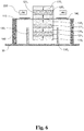
Figure 6 shows a cross-sectional view of the example ofFigure 5 . -
Figure 7 is a series of graphs plotting the variation of potential energy function [U(x)] and restoring force [FR(x)] for different values of the distance d between opposed magnets in several modes including (a) bistable U(x), (b) bistable FR(x), (c) bistable-monostable U(x) and (d) bistable-monostable FR(x). -
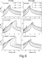
Figure 8(a) - 8(f) are a series of graphs plotting the forward sweep and reverse sweep responses [10 Hz - 90 Hz] of load power against frequency for (a,b) bistable, (c,d) monostable, and (e,f) bistable-monostable combined configurations; and -
Figure 9 is a graph plotting normalized bandwidth against acceleration for bistable, monostable and bistable-monostable combined configurations of the device shown inFigures 1 to 3 , wherein normalized bandwidth is expressed as percentage of peak power frequency (fPeak ). - There will now be described by way of example a specific mode contemplated by the inventors. In the following description numerous specific details are set forth in order to provide a thorough understanding. It will be apparent however, to one skilled in the art, that the present invention may be practiced without limitation to these specific details. In other instances, well known methods and structures have not been described in detail so as not to unnecessarily obscure the description.
- The words "comprises/comprising" and the words "having/including" when used herein with reference to the present invention are used to specify the presence of stated features, integers, steps or components but does not preclude the presence or addition of one or more other features, integers, steps, components or groups thereof.
- The vibrational energy harvesting device described herein was analytically modelled, simulated, fabricated and characterized in nonlinear bistable configuration, both excluding and including the quartic monostable stretching effect. It was observed that, when stretching effects were included (thus combining quartic-monostability) in the bistable energy harvesting system, the harvested frequency bandwidth was enhanced significantly. Thus, the frequency response can be augmented by exploiting both the softening and hardening nonlinearity in the conceptualized device configuration.
- An embodiment of a vibrational
energy harvesting device 10 according to the invention is illustrated inFigures 1 and2 . Thedevice 10 comprises afirst assembly 100 and asecond assembly 200 mounted at a distance one from the other on abase 30. Thefirst assembly 100 comprises anelongate member 110 with a first fixedly supportedextremity 111 and anunsupported extremity 112 longitudinally opposed to the first, wherein theelongate member 110 is made of FR4 (PCB) material using a laser micromachining process. Theelongate member 110 is slotted so as to define a pair oflongitudinal beams opposed extremities - A first magnetised
assembly 120 of four rare earthpermanent magnets 1201-4 for instance made of neodymium material (NdFeB) is mounted to theelongate member 110 within the slotted portion of theelongate member 110, thus between thebeams unsupported extremity 112 of the elongate member. - A
coil 130 is wound using 30 µm diameter enamelled copper wire until the coil dimensions are 6.5 mm outer diameter, 1.15 mm inner diameter, 1 mm thickness, 2500 turns, 720 Ω resistance. Thecoil 130 is arranged at the midpoint of the slotted portion of theelongate member 110, between themagnets 1201-4 within the high fluxgradient magnet assembly 120. - In this embodiment, each
magnet 1201-4 of the firstmagnetised assembly 120 has dimensions of 8mm × 4mm × 2mm (a) and has a polarity along the transverse direction of theelongate member 110, in such a way that a high flux gradient is created within the slotted portion. Furthermore, two high permeability soft magnetic steel blocks 116, 117 are used on both sides of themagnet assembly 120 still between thebeams - A
further magnet 1205 with dimensions of 4mm × 2mm (a) × 1mm with a polarity along the longitudinal direction of theelongate member 110 is attached to the underside of theunsupported extremity 112 and substantially centrally of the twobeams elongate member 110. - The entire
first assembly 100 is supported on fourcylindrical nylon spacers 150. Twospacers first extremity 111. Each of the remaining twospacers respective beam tab portion 118 extending away from the main body of theelongate member 110. - Accordingly, with reference to
Figure 2 , when the mass composed of the firstmagnetised assembly 120 oscillates vertically, a respective portion of eachbeam tab 118 and thespacer extremity 111 and towards theunsupported extremity 112, is subjected to both bending and longitudinal stretching deformation, which introduce a nonlinear restoring force dependent upon the third power of the displacement. - In order to incorporate bistability in the
device 10, thesecond assembly 200 of thedevice 10 comprises at least oneupright member 210 mounted on the base 30 at a distance from thefirst assembly 100, a top face 211 of which supports a secondmagnetised assembly 220, in this embodiment afurther magnet 2201 with dimensions of 4mm × 2mm (a) × 1mm and a polarity opposed to the polarity of themagnet 1205 attached to the underside of theunsupported extremity 112 of thefirst assembly 100. This configuration exerts repulsive force on thetip magnet 1205 of the first assembly, and thus induces bistability into the system dynamics. -
Figure 4 shows a second embodiment of the invention, where the clamping points in the middle of the stretchable cantilevers are adjustable by incorporating roller mechanisms in thespacers piezoelectric material patch 140 can be attached to a bendable section of the cantilever structure, with the capability of transducing beam deflection into electricity. -
Figures 5 and6 show another example not part of the invention, where adiaphragm structure 113 is fixedly clamped at four corners supported by fixed spacers 1401 - 1404. Four adjustable clamps 1501 - 1502 mounted on roller mechanisms can be slided along the four sides to vary the effective vibrating area of the diaphragm. This example also results into variable stiffness and quartic monostable potential due to the variable effective vibrating area. Cylindrical magnets 1201 - 1205 andcoil arrangements 130 can be made near the centre of the diaphragm to implement electromagnetic transduction. An annularpiezoelectric sheet 140 can be attached around the magnet arrangement to transduce diaphragm deflection into electricity. - The modification in the potential energy profile of the bistable-monostable
combined system beams polarized magnets 
transducing magnet assembly 120. - With reference to
Figure 3 , the magnetic interaction potential can be expressed as:
magnet pair centres magnets - With reference to
Figure 3 still, the vertical displacement of theoscillator 110 is denoted by x and r denotes the distance between thecentres polarized tip magnet 1205 and theexternal magnet 220 at the deflected position. The total restoring force experienced by the oscillator is given by:
- The extent of the repulsive magnetic force on the
tip 112 of thecantilever 110 can be controlled by altering d, the distance between thetip magnet 1205 and the externally positionedmagnet 220. Therefore, the magnetic interaction potential and its contribution to the total restoring force can also be modified by adjusting d. - The effect of nonlinear force contribution due to bistability and stretching induced monostable quartic nonlinearity on the potential energy (U(x)) and restoring force (FR (x)) based on the above equations are illustrated in
Figure 7 for different distances (d) between therepulsive magnets - For a larger gap (d = 6mm), the repulsive interaction between the
magnets - As d is decreased, the potential energy profile and restoring force transform into nonlinear bistable in both configurations. While the restoring force for the bistable case follows an almost linear path at large deflections (far away from the x = 0 position), the restoring force for the bistable-monostable combined configuration at similarly large deflections follow a cubic nonlinear force path. This indicates that, for high amplitude oscillation, the dynamics of the
device 10 will be governed mainly by the monostable quartic nonlinearity. On the other hand, in the case of small to moderate amplitude oscillation, the magnetically-induced bistability would have significant effect on the device dynamics. - However, the most favorable effect of inducing monostable hardening nonlinearity into a bistable system is the modest decrease in the relative height of the potential barrier (
Figure 7(c) ) with respect to the potential wells. The resulting reduced barrier can be crossed by the oscillator at lower amplitude vibrations, triggering large amplitude inter-well motion that produces higher energy. The dynamical system equation can be expressed as:
system 10, D is the mechanical damping factor, γ is the electromagnetic coupling factor, I is the current induced in the coil and y = Y0 sin ωt is the displacement due to external vibration. - If the total resistive load in the electrical circuit is denoted by R, the electrical circuit can be represented as:

- In use, the device is excited at different vibrational accelerations (0.02g - 1.6g) within a frequency range of 10 Hz to 90 Hz in both forward and reverse frequency sweep at a sweep rate of 0.333 Hz per second. Three different nonlinear configurations, i.e. bistable, monostable, and a combination of bistable and monostable are investigated. In each case, the output voltage of the
device 10 is measured across an optimum resistive load of 3 kΩ, which was experimentally determined for a linear configuration of the device. - The frequency response plots at different accelerations (0.2g - 1.2g) for the bistable, stretching based monostable and bistable-monostable combined configurations are shown in
Figure 8 . - In order to avoid the stretching effect in the bistable-only configuration, the pair of clamped-guided
beams magnets - In all the cases, the frequency responses show hardening nonlinearity and the forward and reverse sweep responses exhibit hysteretic behavior. All three configurations demonstrate increasing load power and forward sweep jump frequencies with increasing vibrational acceleration. The forward sweep jump frequencies (fPeak ) at 1g acceleration for the bistable, monostable and bistable-monostable combined configurations are 42 Hz, 68.44 Hz and 65.9 Hz respectively. The peak load power (PPeαk ) at 1g acceleration for these three device configurations are 0.727 mW, 1.573 mW and 1.403 mW respectively.
- In all three nonlinear configurations, super-harmonic peaks are also observed near 1/3rd and 1/2 of the linearized resonance frequencies. With increasing acceleration, the half-power bandwidth (BW) of each configuration was also observed to increase. With reference to
Figure 8 , it is apparent that the half-power bandwidth observed for the bistable-monostable combined case is wider than either of the individual bistable or monostable configurations. - It can also be observed from
Figure 8 that in the bistable-monostable combined configuration, the most significant contribution of bistability is in broadening the monostable frequency response towards the lower frequency domain. At a constant applied acceleration level, the vibration amplitude is comparatively higher in the low frequency regime, enabling the oscillator to easily cross the reduced potential barrier of the combined structure (Figure 7(c) ) and perform the large amplitude motion. At 1g acceleration, the BW for the bistable, monostable and bistable-monostable combined configurations are 3.24 Hz, 8.7 Hz and 9.28 Hz respectively. - The dependence of normalized bandwidth, expressed as the percentage of the peak load power frequency or saddle node frequency for each sweep, on the vibrational acceleration, is depicted in
Figure 9 . - At 0.2g, the normalized bandwidth BW for the bistable, monostable and bistable-monostable combined configurations are 4.24%, 5.56% and 9.75% of fPeak respectively. As the applied vibrational acceleration is increased in steps, the normalized bandwidth also increases for the three configurations. At the highest acceleration level (1.6g) the normalized bandwidths become 8.66%, 13.83% and 14.99% of fPeak for the bistable, monostable and bistable-monostable combined configurations respectively.
- Thus, with increasing acceleration, the bandwidth widening effect of bistable-monostable combined configuration become less significant in comparison to the individual bistable and monostable cases. This is because of the fact that with increasing acceleration the amplitude of oscillation increases, resulting in higher nonlinear stretching strain in both monostable and the bistable-monostable combined configuration (
Figure 7(d) ). - Therefore, with higher acceleration the cubic nonlinear restoring force in the system is enhanced, which contributes to the broader frequency bandwidth. On decreasing the vibrational acceleration below 0.2g, the contribution of the monostable quartic nonlinearity (3.458% of fPeak at 0.1g) in the bandwidth is reduced in comparison to the contribution from bistability (4.082% of fPeak at 0.1g). The diminished contribution of the stretching-based monostable quartic nonlinearity in the bandwidth is due to reduced vibrational amplitude at lower accelerations.
- On the other hand, the bistable nonlinearity is most effective in the low amplitude oscillation scenario (
Figures 7(c), 7(d) ) and contributes significantly towards the bandwidth of the bistable-monostable combined configuration below 0.1g acceleration. Effectively, bistable-monostable combined configuration achieves much wider bandwidth (8.093% of fPeak at 0.1g) in comparison to the individual bistable (4.082% of fPeak at 0.1g) or monostable (3.458% of fPeak at 0.1g) configurations. - The performances of all the different configurations of the proposed
device 10 in random vibration environment are investigated in an applied band-limited (10 - 500Hz) random vibration with low (8×10⁻³ g2/Hz, 0.2g RMS), medium (2×10⁻³ g2/Hz, 1g RMS), and high (8×10⁻³ g2/Hz, 2g RMS) accelerations. The resulting PSDs of the linear device produce sharp peak at 43.1 Hz for all accelerations. As bistability is incorporated by reducing the gap (d = 4mm) between the repulsively positioned magnets, the peak shifts towards lower frequencies and is broadened. The potential barrier between the two bistable potential wells is small (Figure 7(a) ) in this configuration and can be passed over by the oscillator at all accelerations. However, on decreasing the gap further (d = 3.5mm) the potential barrier in the bistable configuration become higher (Figure 7(a) ), resulting in confinement of the oscillator in a single potential well and increased stiffness. Consequently, the PSDs in this configuration exhibit sharp peaks similar to the linear configuration, near 50 Hz at low and medium accelerations. - At high acceleration this configuration may perform chaotic jumps between the potential wells, giving rise to broader response with a peak near 50 Hz. The monostable nonlinear variant of the device produces steep peaks, resembling the linear device, near 46 Hz at all acceleration levels. As bistability is introduced into the monostable configuration (d = 4mm), the peak is broadened and shifted to the lower frequency domain for all accelerations. On decreasing the gap further (d = 3.5mm), the response of the bistable-monostable combined configuration produces even wider response, unlike the bistable-only variant, at all accelerations. This can be attributed to the higher restoring force and lowering of the bistable potential barrier height (
Figure 7(c), 7(d) ) due to the incorporation of monostable quartic nonlinearity, which enables the oscillator to perform inter-well jump at all vibrational accelerations. In general, the bistable-monostable combined configuration exhibits broader bandwidth under all vibrational accelerations, in comparison to the individual bistable or monostable variants. - In conclusion, a novel device architecture has been developed, which exploits both bistable and monostable quartic nonlinearity simultaneously in a vibrational energy harvesting device for wider bandwidth. The modified potential energy profile due to the combined nonlinearity results into higher restoring force during oscillation and activates large amplitude inter-well motion at relatively lower accelerations due to the reduced potential barrier.
- An
embodiment 10 has been described wherein monostable quartic nonlinearity is incorporated by a pair of clamped guidedbeams magnets - Experimentally, it has been observed that the bandwidth of the bistable-monostable combined configuration is broadened towards the lower frequency regime in comparison to the individual bistable or monostable systems, and produces bandwidth of 9.95% of peak power frequency at 0.2g acceleration, whereas the same values for the individual bistable and monostable systems are 4.54% and 5.66% respectively. This effect is due to potential well modification and the broadening effect is more pronounced at the lower accelerations under harmonic excitations.
- At 1g acceleration the bistable-monostable combined configuration produced a peak load power of 1.403 mW at a peak power frequency of 65.9 Hz and achieved a half -power bandwidth of 9.282 Hz (14.08 % of peak power frequency). Additionally, under band-limited random vibration the bistable-monostable combined configuration attained a wider power spectral density in comparison to the individual systems, as it is enabled to perform cross-well jump due to the higher restoring force and reduced potential barrier. The proposed bistable-monostable combined device topology could be further modified and implemented in other transduction (piezoelectric, electrostatic, triboelectric) mechanisms for different wideband practical application scenario.
- The embodiment may be further miniaturized to the MEMS (Micro-Electro-Mechanical Systems) scale where the stretchable spring or diaphragm is fabricated on silicon or silicon-on-insulator (SOI) wafer using standard microfabrication techniques or on other metal or polymer material. The copper coil may also be microfabricated and integrated on the spring platform. Rare earth or non-rare earth permanent magnets may be fabricated using sputtering, electrodeposition or other physical or chemical deposition techniques to facilitate complete integration of the device.
- In the specification the terms "comprise, comprises, comprised and comprising" or any variation thereof and the terms include, includes, included and including" or any variation thereof are considered to be totally interchangeable and they should all be afforded the widest possible interpretation and vice versa.
- The invention is not limited to the embodiments hereinbefore described but may be varied in both construction and detail.
Claims (13)
- A broadband vibrational energy harvesting device adapted to simultaneously combine bistable and monostable quartic potential energy profiles, the device comprising
first (100) and second (200) assemblies mounted at a distance one from the other;
wherein the first assembly (100) comprises vibrational means comprising a clamped guided cantilever (110) adapted to stretch under a straining force, whereby the device exhibits quartic monostable nonlinearity;
wherein the first (100) and second (200) assemblies comprise respective magnetised means in opposite polarity to one another, so that the second assembly (200) exerts a repulsive magnetic force upon the vibrational means, whereby the device exhibits bistability;
wherein the clamped guided cantilever (110) comprises at least one fixedly supported extremity (111) and at least one unsupported extremity (112) longitudinally opposed to the supported extremity (111),
the magnetised means of the first assembly (100) comprises a first magnetised assembly (120) mounted to the clamped guided cantilever (110) proximate the unsupported extremity (112) of the clamped guided cantilever (110), having at least one magnet with polarity along a longitudinal direction of the clamped guided cantilever (110); and
the magnetised means of the second assembly (200) comprises a second magnetised assembly (220) located adjacent the unsupported extremity (112) of the first assembly (100), at the distance between the first (100) and second (200) assemblies, and in opposite polarity to the first magnetised assembly (120) such that the repulsive magnetic forces between the first assembly (100) and the second assembly (200) causes multiple equilibrium states; the device being characterized in that the clamping point of the clamped guided cantilever (110) is in the middle of the cantilever (110) and is adjustable to vary the quartic monostable nonlinearity. - A vibrational energy harvesting device according to claim 1, wherein the bistable and monostable quartic potential energy profiles are adapted to be independently modified.
- A vibrational energy harvesting device according to claim 1 or claim 2, further comprising at least one piezoelectric element (140) attached to the clamped-guided cantilever (110) for transducing deflection into electricity.
- A vibrational energy harvesting device according to any of claims 1 to 3, wherein the repulsive magnetic force is adjustable as a function of the distance between the first (120) and the second (220) magnetised assemblies.
- A vibrational energy harvesting device according to any of claims 1 to 4, wherein the first magnetised assembly (120) comprises a plurality of magnets, generating a high flux gradient, the device further comprising a coil (130) arranged between the magnets.
- A vibrational energy harvesting device according to claim 5, wherein the second assembly (200) of the device comprises at least one support member (210) and wherein the second magnetised assembly (220) comprises at least one magnet secured to the at least one support member (210).
- A vibrational energy harvesting device according to claim 5 or 6, wherein the device further comprises at least one magnet (1205) fixed to the clamped-guided cantilever (110) substantially at the unsupported extremity (112), substantially intermediate the first (120) and second (220) magnetised assemblies, having a polarity in the longitudinal direction of the clamped-guided cantilever (110) such that magnetic repulsion is established between the first (120) and second (220) magnetised assembly.
- A vibrational energy harvesting device according to any of claims 5 to 7, wherein the first magnetised assembly (120) further comprises a plurality of high permeability soft magnetic steel blocks or plates (116; 117) arranged adjacent the plurality of magnets so as to intensify the magnetic flux thereof.
- A vibrational energy harvesting device according to any of the preceding claims, wherein the clamped-guided cantilever (110) is slotted so as to define a pair of longitudinal beams (113; 114) and wherein the first magnetised assembly (120) is mounted within the slot between the beams (113;114).
- A vibrational energy harvesting device according to any of claims 1 to 9, further comprising means for detecting a low power output of the device operably coupled with means for perturbing and/or driving the first assembly (100) into a high amplitude motion according to a detection output.
- A vibrational energy harvesting device according to claim 10, wherein the driving means comprises the vibrational means coupled with an energy storage module adapted to actuate, or at least momentarily perturb, the first assembly (100).
- A vibrational energy harvesting device according to claim 10 or 11, wherein the means to detect is a voltage comparator circuit.
- A method of harvesting energy with a broadband vibrational energy harvesting device adapted to simultaneously combine bistable and monostable quartic potential energy profiles, the method comprising the steps of
providing a first assembly (100) of the device comprising a clamped guided cantilever (110) comprising first magnetised means having a polarity and vibrational means adapted to stretch under a straining force, whereby the device exhibits quartic monostable nonlinearity;
wherein the clamped guided cantilever (110) comprises at least one fixedly supported extremity (111) and at least one unsupported extremity (112) longitudinally opposed to the supported extremity, the first magnetised means comprising a first magnetised assembly (120) mounted to the clamped guided cantilever (110) proximate the unsupported extremity (112) of the clamped guided cantilever (110), having at least one magnet with polarity along a longitudinal direction of the clamped guided cantilever;
providing a second assembly (200) of the device, comprising second magnetised means having a polarity opposite to the polarity of the first magnetised means;
mounting the first and second assembly (100, 200) at a distance one from the other; wherein the second magnetised means comprises a second magnetised assembly located adjacent the unsupported extremity of the first assembly (100), at the distance between the first and second assemblies (100, 200), and in opposite polarity to the first magnetised assembly (120) such that the repulsive magnetic forces between the first assembly (100) and the second assembly (100) causes multiple equilibrium states; and
subjecting the device to a force apt to induce vibration in the first assembly; wherein the clamping point of the clamped guided cantilever is in the middle of the cantilever and is adjustable to vary the quartic monostable nonlinearity.
Applications Claiming Priority (2)
| Application Number | Priority Date | Filing Date | Title |
|---|---|---|---|
| GBGB1510794.9A GB201510794D0 (en) | 2015-06-19 | 2015-06-19 | Vibrational Energy Harvesting Device Combining Multiple Nonlinearity |
| PCT/EP2016/063940 WO2016202948A1 (en) | 2015-06-19 | 2016-06-16 | Broadband vibrational energy harvesting device combining multiple nonlinearity |
Publications (2)
| Publication Number | Publication Date |
|---|---|
| EP3311472A1 EP3311472A1 (en) | 2018-04-25 |
| EP3311472B1 true EP3311472B1 (en) | 2020-01-01 |
Family
ID=53784185
Family Applications (1)
| Application Number | Title | Priority Date | Filing Date |
|---|---|---|---|
| EP16736001.5A Active EP3311472B1 (en) | 2015-06-19 | 2016-06-16 | Broadband vibrational energy harvesting device combining multiple nonlinearity |
Country Status (4)
| Country | Link |
|---|---|
| US (1) | US10971986B2 (en) |
| EP (1) | EP3311472B1 (en) |
| GB (1) | GB201510794D0 (en) |
| WO (1) | WO2016202948A1 (en) |
Families Citing this family (12)
| Publication number | Priority date | Publication date | Assignee | Title |
|---|---|---|---|---|
| GB201510794D0 (en) | 2015-06-19 | 2015-08-05 | Univ College Cork Nat Univ Ie | Vibrational Energy Harvesting Device Combining Multiple Nonlinearity |
| JP6643697B2 (en) * | 2015-09-24 | 2020-02-12 | ミツミ電機株式会社 | Electromagnetic transducer, actuator, and pump |
| US10447135B2 (en) * | 2015-09-28 | 2019-10-15 | The Curators Of The University Of Missouri | Device for generating electrical power from low frequency oscillations |
| US10704990B2 (en) * | 2018-03-13 | 2020-07-07 | Aktiebolaget Skf | Spacer and sensor module for detecting a vibrational behavior of a mechanical component including the spacer |
| GB2572572B (en) * | 2018-04-03 | 2022-03-09 | 8Power Ltd | Energy harvester for harvesting energy from broadband ambient vibrations |
| CN111024276A (en) * | 2019-12-26 | 2020-04-17 | 王丽霞 | A mounting bracket for installing piezoelectric material |
| JP7491120B2 (en) * | 2020-07-28 | 2024-05-28 | セイコーエプソン株式会社 | Monitoring devices and equipment |
| CN112583227B (en) * | 2020-11-26 | 2022-03-15 | 南京高华科技股份有限公司 | MEMS inductive vibration energy collector and preparation method thereof |
| CN112671261B (en) * | 2020-12-18 | 2023-07-21 | 上海科技大学 | Transient motion energy harvester and transient motion energy supply IoT sensor node equipment |
| CN113358071B (en) * | 2021-06-08 | 2022-07-19 | 西南交通大学 | A self-powered bridge structure displacement monitoring device and method |
| CN115051527B (en) * | 2022-06-27 | 2024-05-24 | 华中科技大学 | Bistable nonlinear energy harvesting device and method of using the same |
| CN119358058B (en) * | 2024-12-24 | 2025-03-28 | 西北工业大学 | A method and device for analyzing nonlinear vibration characteristics of three-dimensional serpentine structures |
Family Cites Families (4)
| Publication number | Priority date | Publication date | Assignee | Title |
|---|---|---|---|---|
| GB2429337B (en) * | 2005-08-15 | 2009-10-14 | Perpetuum Ltd | An electromechanical generator for converting mechanical vibrational energy into electrical energy |
| US7986051B2 (en) * | 2007-05-30 | 2011-07-26 | Humdinger Wind Enery LLC | Energy converters utilizing fluid-induced oscillations |
| WO2009039293A1 (en) * | 2007-09-18 | 2009-03-26 | University Of Florida Research Foundation, Inc. | Dul-mode piezoelectric/magnetic vibrational energy harvester |
| GB201510794D0 (en) | 2015-06-19 | 2015-08-05 | Univ College Cork Nat Univ Ie | Vibrational Energy Harvesting Device Combining Multiple Nonlinearity |
-
2015
- 2015-06-19 GB GBGB1510794.9A patent/GB201510794D0/en not_active Ceased
-
2016
- 2016-06-16 EP EP16736001.5A patent/EP3311472B1/en active Active
- 2016-06-16 WO PCT/EP2016/063940 patent/WO2016202948A1/en not_active Ceased
- 2016-06-16 US US15/737,275 patent/US10971986B2/en active Active
Non-Patent Citations (2)
| Title |
|---|
| COTTONE F ET AL: "Electromagnetic Buckled Beam Oscillator for Enhanced Vibration Energy Harvesting", GREEN COMPUTING AND COMMUNICATIONS (GREENCOM), 2012 IEEE INTERNATIONAL CONFERENCE ON, IEEE, 20 November 2012 (2012-11-20), pages 624 - 627, XP032337324, ISBN: 978-1-4673-5146-1, DOI: 10.1109/GREENCOM.2012.151 * |
| RAVINDRA MASANA ET AL: "Relative performance of a vibratory energy harvester in mono- and bi-stable potentials", JOURNAL OF SOUND AND VIBRATION, ELSEVIER, AMSTERDAM, NL, vol. 330, no. 24, 22 July 2011 (2011-07-22), pages 6036 - 6052, XP028276018, ISSN: 0022-460X, [retrieved on 20110730], DOI: 10.1016/J.JSV.2011.07.031 * |
Also Published As
| Publication number | Publication date |
|---|---|
| US20180191231A1 (en) | 2018-07-05 |
| US10971986B2 (en) | 2021-04-06 |
| EP3311472A1 (en) | 2018-04-25 |
| GB201510794D0 (en) | 2015-08-05 |
| WO2016202948A1 (en) | 2016-12-22 |
Similar Documents
| Publication | Publication Date | Title |
|---|---|---|
| US10971986B2 (en) | Broadband vibrational energy harvesting device combining multiple nonlinearity | |
| US20110074247A1 (en) | Systems and Methods for Resonance Frequency Tuning of Micromachined Structures | |
| Challa et al. | Towards an autonomous self-tuning vibration energy harvesting device for wireless sensor network applications | |
| Wang et al. | Low-frequency wideband vibration energy harvesting by using frequency up-conversion and quin-stable nonlinearity | |
| Andò et al. | Nonlinear mechanism in MEMS devices for energy harvesting applications | |
| Gu | Low-frequency piezoelectric energy harvesting prototype suitable for the MEMS implementation | |
| Wu et al. | Non-contact magnetic cantilever-type piezoelectric energy harvester for rotational mechanism | |
| EP3245156B1 (en) | Miniature kinetic energy harvester for generating electrical energy from mechanical vibrations | |
| EP2856628B1 (en) | Energy-harvesting apparatus and method | |
| Ju et al. | Macro fiber composite-based low frequency vibration energy harvester | |
| Li et al. | A resonant frequency self-tunable rotation energy harvester based on magnetoelectric transducer | |
| Chiacchiari et al. | Vibration energy harvesting from impulsive excitations via a bistable nonlinear attachment—experimental study | |
| US11005352B2 (en) | Device for generating electrical power from low frequency oscillations | |
| WO2010151738A2 (en) | Piezomagnetoelastic structure for broadband vibration energy harvesting | |
| Podder et al. | A bistable electromagnetic micro-power generator using FR4-based folded arm cantilever | |
| WO2019193323A1 (en) | Energy harvester for harvesting energy from broadband ambient vibrations | |
| Su et al. | Investigations of a stiffness tunable nonlinear vibrational energy harvester | |
| Larcher et al. | Vibrational energy harvesting | |
| Beeby | Energy harvesting devices | |
| Swee-Leong et al. | Multi-frequency energy harvesting using thick-film piezoelectric cantilever | |
| Djokoto et al. | Experimental investigation of squeezed MRF film stopper and its effect on vibrating bimorph for frequency tuning of an energy generator | |
| Nico et al. | A c-battery scale energy harvester: part a—system dynamics | |
| Karami et al. | Experimental study of the nonlinear hybrid energy harvesting system | |
| Podder et al. | Bandwidth widening in nonlinear electromagnetic vibrational generator by combined effect of bistability and stretching | |
| Cronin et al. | A Comparison of Two Planar Electromagnetic Vibrational Energy Harvesters Designs |
Legal Events
| Date | Code | Title | Description |
|---|---|---|---|
| STAA | Information on the status of an ep patent application or granted ep patent |
Free format text: STATUS: THE INTERNATIONAL PUBLICATION HAS BEEN MADE |
|
| PUAI | Public reference made under article 153(3) epc to a published international application that has entered the european phase |
Free format text: ORIGINAL CODE: 0009012 |
|
| STAA | Information on the status of an ep patent application or granted ep patent |
Free format text: STATUS: REQUEST FOR EXAMINATION WAS MADE |
|
| 17P | Request for examination filed |
Effective date: 20180118 |
|
| AK | Designated contracting states |
Kind code of ref document: A1 Designated state(s): AL AT BE BG CH CY CZ DE DK EE ES FI FR GB GR HR HU IE IS IT LI LT LU LV MC MK MT NL NO PL PT RO RS SE SI SK SM TR |
|
| AX | Request for extension of the european patent |
Extension state: BA ME |
|
| DAV | Request for validation of the european patent (deleted) | ||
| DAX | Request for extension of the european patent (deleted) | ||
| STAA | Information on the status of an ep patent application or granted ep patent |
Free format text: STATUS: EXAMINATION IS IN PROGRESS |
|
| 17Q | First examination report despatched |
Effective date: 20181002 |
|
| GRAP | Despatch of communication of intention to grant a patent |
Free format text: ORIGINAL CODE: EPIDOSNIGR1 |
|
| STAA | Information on the status of an ep patent application or granted ep patent |
Free format text: STATUS: GRANT OF PATENT IS INTENDED |
|
| INTG | Intention to grant announced |
Effective date: 20190403 |
|
| GRAS | Grant fee paid |
Free format text: ORIGINAL CODE: EPIDOSNIGR3 |
|
| GRAA | (expected) grant |
Free format text: ORIGINAL CODE: 0009210 |
|
| STAA | Information on the status of an ep patent application or granted ep patent |
Free format text: STATUS: THE PATENT HAS BEEN GRANTED |
|
| AK | Designated contracting states |
Kind code of ref document: B1 Designated state(s): AL AT BE BG CH CY CZ DE DK EE ES FI FR GB GR HR HU IE IS IT LI LT LU LV MC MK MT NL NO PL PT RO RS SE SI SK SM TR |
|
| REG | Reference to a national code |
Ref country code: GB Ref legal event code: FG4D |
|
| REG | Reference to a national code |
Ref country code: CH Ref legal event code: EP Ref country code: AT Ref legal event code: REF Ref document number: 1221033 Country of ref document: AT Kind code of ref document: T Effective date: 20200115 |
|
| REG | Reference to a national code |
Ref country code: IE Ref legal event code: FG4D |
|
| REG | Reference to a national code |
Ref country code: DE Ref legal event code: R096 Ref document number: 602016027312 Country of ref document: DE |
|
| REG | Reference to a national code |
Ref country code: NL Ref legal event code: FP |
|
| REG | Reference to a national code |
Ref country code: LT Ref legal event code: MG4D |
|
| PG25 | Lapsed in a contracting state [announced via postgrant information from national office to epo] |
Ref country code: LT Free format text: LAPSE BECAUSE OF FAILURE TO SUBMIT A TRANSLATION OF THE DESCRIPTION OR TO PAY THE FEE WITHIN THE PRESCRIBED TIME-LIMIT Effective date: 20200101 Ref country code: NO Free format text: LAPSE BECAUSE OF FAILURE TO SUBMIT A TRANSLATION OF THE DESCRIPTION OR TO PAY THE FEE WITHIN THE PRESCRIBED TIME-LIMIT Effective date: 20200401 Ref country code: CZ Free format text: LAPSE BECAUSE OF FAILURE TO SUBMIT A TRANSLATION OF THE DESCRIPTION OR TO PAY THE FEE WITHIN THE PRESCRIBED TIME-LIMIT Effective date: 20200101 Ref country code: PT Free format text: LAPSE BECAUSE OF FAILURE TO SUBMIT A TRANSLATION OF THE DESCRIPTION OR TO PAY THE FEE WITHIN THE PRESCRIBED TIME-LIMIT Effective date: 20200527 Ref country code: RS Free format text: LAPSE BECAUSE OF FAILURE TO SUBMIT A TRANSLATION OF THE DESCRIPTION OR TO PAY THE FEE WITHIN THE PRESCRIBED TIME-LIMIT Effective date: 20200101 Ref country code: FI Free format text: LAPSE BECAUSE OF FAILURE TO SUBMIT A TRANSLATION OF THE DESCRIPTION OR TO PAY THE FEE WITHIN THE PRESCRIBED TIME-LIMIT Effective date: 20200101 |
|
| PG25 | Lapsed in a contracting state [announced via postgrant information from national office to epo] |
Ref country code: HR Free format text: LAPSE BECAUSE OF FAILURE TO SUBMIT A TRANSLATION OF THE DESCRIPTION OR TO PAY THE FEE WITHIN THE PRESCRIBED TIME-LIMIT Effective date: 20200101 Ref country code: GR Free format text: LAPSE BECAUSE OF FAILURE TO SUBMIT A TRANSLATION OF THE DESCRIPTION OR TO PAY THE FEE WITHIN THE PRESCRIBED TIME-LIMIT Effective date: 20200402 Ref country code: IS Free format text: LAPSE BECAUSE OF FAILURE TO SUBMIT A TRANSLATION OF THE DESCRIPTION OR TO PAY THE FEE WITHIN THE PRESCRIBED TIME-LIMIT Effective date: 20200501 Ref country code: BG Free format text: LAPSE BECAUSE OF FAILURE TO SUBMIT A TRANSLATION OF THE DESCRIPTION OR TO PAY THE FEE WITHIN THE PRESCRIBED TIME-LIMIT Effective date: 20200401 Ref country code: LV Free format text: LAPSE BECAUSE OF FAILURE TO SUBMIT A TRANSLATION OF THE DESCRIPTION OR TO PAY THE FEE WITHIN THE PRESCRIBED TIME-LIMIT Effective date: 20200101 Ref country code: SE Free format text: LAPSE BECAUSE OF FAILURE TO SUBMIT A TRANSLATION OF THE DESCRIPTION OR TO PAY THE FEE WITHIN THE PRESCRIBED TIME-LIMIT Effective date: 20200101 |
|
| REG | Reference to a national code |
Ref country code: DE Ref legal event code: R097 Ref document number: 602016027312 Country of ref document: DE |
|
| PG25 | Lapsed in a contracting state [announced via postgrant information from national office to epo] |
Ref country code: RO Free format text: LAPSE BECAUSE OF FAILURE TO SUBMIT A TRANSLATION OF THE DESCRIPTION OR TO PAY THE FEE WITHIN THE PRESCRIBED TIME-LIMIT Effective date: 20200101 Ref country code: EE Free format text: LAPSE BECAUSE OF FAILURE TO SUBMIT A TRANSLATION OF THE DESCRIPTION OR TO PAY THE FEE WITHIN THE PRESCRIBED TIME-LIMIT Effective date: 20200101 Ref country code: SM Free format text: LAPSE BECAUSE OF FAILURE TO SUBMIT A TRANSLATION OF THE DESCRIPTION OR TO PAY THE FEE WITHIN THE PRESCRIBED TIME-LIMIT Effective date: 20200101 Ref country code: DK Free format text: LAPSE BECAUSE OF FAILURE TO SUBMIT A TRANSLATION OF THE DESCRIPTION OR TO PAY THE FEE WITHIN THE PRESCRIBED TIME-LIMIT Effective date: 20200101 Ref country code: ES Free format text: LAPSE BECAUSE OF FAILURE TO SUBMIT A TRANSLATION OF THE DESCRIPTION OR TO PAY THE FEE WITHIN THE PRESCRIBED TIME-LIMIT Effective date: 20200101 Ref country code: SK Free format text: LAPSE BECAUSE OF FAILURE TO SUBMIT A TRANSLATION OF THE DESCRIPTION OR TO PAY THE FEE WITHIN THE PRESCRIBED TIME-LIMIT Effective date: 20200101 |
|
| PLBE | No opposition filed within time limit |
Free format text: ORIGINAL CODE: 0009261 |
|
| STAA | Information on the status of an ep patent application or granted ep patent |
Free format text: STATUS: NO OPPOSITION FILED WITHIN TIME LIMIT |
|
| REG | Reference to a national code |
Ref country code: AT Ref legal event code: MK05 Ref document number: 1221033 Country of ref document: AT Kind code of ref document: T Effective date: 20200101 |
|
| 26N | No opposition filed |
Effective date: 20201002 |
|
| PG25 | Lapsed in a contracting state [announced via postgrant information from national office to epo] |
Ref country code: AT Free format text: LAPSE BECAUSE OF FAILURE TO SUBMIT A TRANSLATION OF THE DESCRIPTION OR TO PAY THE FEE WITHIN THE PRESCRIBED TIME-LIMIT Effective date: 20200101 Ref country code: MC Free format text: LAPSE BECAUSE OF FAILURE TO SUBMIT A TRANSLATION OF THE DESCRIPTION OR TO PAY THE FEE WITHIN THE PRESCRIBED TIME-LIMIT Effective date: 20200101 |
|
| REG | Reference to a national code |
Ref country code: CH Ref legal event code: PL |
|
| PG25 | Lapsed in a contracting state [announced via postgrant information from national office to epo] |
Ref country code: PL Free format text: LAPSE BECAUSE OF FAILURE TO SUBMIT A TRANSLATION OF THE DESCRIPTION OR TO PAY THE FEE WITHIN THE PRESCRIBED TIME-LIMIT Effective date: 20200101 Ref country code: SI Free format text: LAPSE BECAUSE OF FAILURE TO SUBMIT A TRANSLATION OF THE DESCRIPTION OR TO PAY THE FEE WITHIN THE PRESCRIBED TIME-LIMIT Effective date: 20200101 |
|
| PG25 | Lapsed in a contracting state [announced via postgrant information from national office to epo] |
Ref country code: LU Free format text: LAPSE BECAUSE OF NON-PAYMENT OF DUE FEES Effective date: 20200616 |
|
| REG | Reference to a national code |
Ref country code: BE Ref legal event code: MM Effective date: 20200630 |
|
| PG25 | Lapsed in a contracting state [announced via postgrant information from national office to epo] |
Ref country code: CH Free format text: LAPSE BECAUSE OF NON-PAYMENT OF DUE FEES Effective date: 20200630 Ref country code: LI Free format text: LAPSE BECAUSE OF NON-PAYMENT OF DUE FEES Effective date: 20200630 |
|
| PG25 | Lapsed in a contracting state [announced via postgrant information from national office to epo] |
Ref country code: BE Free format text: LAPSE BECAUSE OF NON-PAYMENT OF DUE FEES Effective date: 20200630 |
|
| PG25 | Lapsed in a contracting state [announced via postgrant information from national office to epo] |
Ref country code: TR Free format text: LAPSE BECAUSE OF FAILURE TO SUBMIT A TRANSLATION OF THE DESCRIPTION OR TO PAY THE FEE WITHIN THE PRESCRIBED TIME-LIMIT Effective date: 20200101 Ref country code: MT Free format text: LAPSE BECAUSE OF FAILURE TO SUBMIT A TRANSLATION OF THE DESCRIPTION OR TO PAY THE FEE WITHIN THE PRESCRIBED TIME-LIMIT Effective date: 20200101 Ref country code: CY Free format text: LAPSE BECAUSE OF FAILURE TO SUBMIT A TRANSLATION OF THE DESCRIPTION OR TO PAY THE FEE WITHIN THE PRESCRIBED TIME-LIMIT Effective date: 20200101 |
|
| PG25 | Lapsed in a contracting state [announced via postgrant information from national office to epo] |
Ref country code: MK Free format text: LAPSE BECAUSE OF FAILURE TO SUBMIT A TRANSLATION OF THE DESCRIPTION OR TO PAY THE FEE WITHIN THE PRESCRIBED TIME-LIMIT Effective date: 20200101 Ref country code: AL Free format text: LAPSE BECAUSE OF FAILURE TO SUBMIT A TRANSLATION OF THE DESCRIPTION OR TO PAY THE FEE WITHIN THE PRESCRIBED TIME-LIMIT Effective date: 20200101 |
|
| PGFP | Annual fee paid to national office [announced via postgrant information from national office to epo] |
Ref country code: DE Payment date: 20250626 Year of fee payment: 10 |
|
| PGFP | Annual fee paid to national office [announced via postgrant information from national office to epo] |
Ref country code: GB Payment date: 20250624 Year of fee payment: 10 |
|
| PGFP | Annual fee paid to national office [announced via postgrant information from national office to epo] |
Ref country code: NL Payment date: 20250624 Year of fee payment: 10 |
|
| PGFP | Annual fee paid to national office [announced via postgrant information from national office to epo] |
Ref country code: FR Payment date: 20250625 Year of fee payment: 10 |
|
| PGFP | Annual fee paid to national office [announced via postgrant information from national office to epo] |
Ref country code: IE Payment date: 20250624 Year of fee payment: 10 |
|
| PGFP | Annual fee paid to national office [announced via postgrant information from national office to epo] |
Ref country code: IT Payment date: 20250625 Year of fee payment: 10 |