EP3310643B1 - Liftable axle suspension - Google Patents
Liftable axle suspension Download PDFInfo
- Publication number
- EP3310643B1 EP3310643B1 EP15895806.6A EP15895806A EP3310643B1 EP 3310643 B1 EP3310643 B1 EP 3310643B1 EP 15895806 A EP15895806 A EP 15895806A EP 3310643 B1 EP3310643 B1 EP 3310643B1
- Authority
- EP
- European Patent Office
- Prior art keywords
- joints
- pivotable
- axle
- hanger
- frame
- Prior art date
- Legal status (The legal status is an assumption and is not a legal conclusion. Google has not performed a legal analysis and makes no representation as to the accuracy of the status listed.)
- Not-in-force
Links
Images




Classifications
-
- B—PERFORMING OPERATIONS; TRANSPORTING
- B60—VEHICLES IN GENERAL
- B60G—VEHICLE SUSPENSION ARRANGEMENTS
- B60G9/00—Resilient suspensions of a rigid axle or axle housing for two or more wheels
- B60G9/02—Resilient suspensions of a rigid axle or axle housing for two or more wheels the axle or housing being pivotally mounted on the vehicle, e.g. the pivotal axis being parallel to the longitudinal axis of the vehicle
- B60G9/022—Resilient suspensions of a rigid axle or axle housing for two or more wheels the axle or housing being pivotally mounted on the vehicle, e.g. the pivotal axis being parallel to the longitudinal axis of the vehicle the axle having an imaginary pivotal point
- B60G9/025—Resilient suspensions of a rigid axle or axle housing for two or more wheels the axle or housing being pivotally mounted on the vehicle, e.g. the pivotal axis being parallel to the longitudinal axis of the vehicle the axle having an imaginary pivotal point using linkages for the suspension of the axle allowing its lateral swinging displacement
-
- B—PERFORMING OPERATIONS; TRANSPORTING
- B62—LAND VEHICLES FOR TRAVELLING OTHERWISE THAN ON RAILS
- B62D—MOTOR VEHICLES; TRAILERS
- B62D61/00—Motor vehicles or trailers, characterised by the arrangement or number of wheels, not otherwise provided for, e.g. four wheels in diamond pattern
- B62D61/12—Motor vehicles or trailers, characterised by the arrangement or number of wheels, not otherwise provided for, e.g. four wheels in diamond pattern with variable number of ground engaging wheels, e.g. with some wheels arranged higher than others, or with retractable wheels
-
- B—PERFORMING OPERATIONS; TRANSPORTING
- B60—VEHICLES IN GENERAL
- B60G—VEHICLE SUSPENSION ARRANGEMENTS
- B60G11/00—Resilient suspensions characterised by arrangement, location or kind of springs
- B60G11/26—Resilient suspensions characterised by arrangement, location or kind of springs having fluid springs only, e.g. hydropneumatic springs
- B60G11/27—Resilient suspensions characterised by arrangement, location or kind of springs having fluid springs only, e.g. hydropneumatic springs wherein the fluid is a gas
-
- B—PERFORMING OPERATIONS; TRANSPORTING
- B60—VEHICLES IN GENERAL
- B60G—VEHICLE SUSPENSION ARRANGEMENTS
- B60G9/00—Resilient suspensions of a rigid axle or axle housing for two or more wheels
- B60G9/02—Resilient suspensions of a rigid axle or axle housing for two or more wheels the axle or housing being pivotally mounted on the vehicle, e.g. the pivotal axis being parallel to the longitudinal axis of the vehicle
-
- B—PERFORMING OPERATIONS; TRANSPORTING
- B60—VEHICLES IN GENERAL
- B60G—VEHICLE SUSPENSION ARRANGEMENTS
- B60G2200/00—Indexing codes relating to suspension types
- B60G2200/30—Rigid axle suspensions
- B60G2200/314—Rigid axle suspensions with longitudinally arranged arms articulated on the axle
-
- B—PERFORMING OPERATIONS; TRANSPORTING
- B60—VEHICLES IN GENERAL
- B60G—VEHICLE SUSPENSION ARRANGEMENTS
- B60G2200/00—Indexing codes relating to suspension types
- B60G2200/30—Rigid axle suspensions
- B60G2200/34—Stabilising mechanisms, e.g. for lateral stability
- B60G2200/346—Stabilising mechanisms, e.g. for lateral stability with an axle suspended by two laterally displaced rods having an imaginary point of intersection above the wheel axis
-
- B—PERFORMING OPERATIONS; TRANSPORTING
- B60—VEHICLES IN GENERAL
- B60G—VEHICLE SUSPENSION ARRANGEMENTS
- B60G2200/00—Indexing codes relating to suspension types
- B60G2200/30—Rigid axle suspensions
- B60G2200/34—Stabilising mechanisms, e.g. for lateral stability
- B60G2200/347—Stabilising mechanisms, e.g. for lateral stability with an axle suspended by two laterally displaced rods having an imaginary point of intersection below the wheel axis
-
- B—PERFORMING OPERATIONS; TRANSPORTING
- B60—VEHICLES IN GENERAL
- B60G—VEHICLE SUSPENSION ARRANGEMENTS
- B60G2200/00—Indexing codes relating to suspension types
- B60G2200/40—Indexing codes relating to the wheels in the suspensions
- B60G2200/445—Self-steered wheels
-
- B—PERFORMING OPERATIONS; TRANSPORTING
- B60—VEHICLES IN GENERAL
- B60G—VEHICLE SUSPENSION ARRANGEMENTS
- B60G2202/00—Indexing codes relating to the type of spring, damper or actuator
- B60G2202/10—Type of spring
- B60G2202/15—Fluid spring
- B60G2202/152—Pneumatic spring
-
- B—PERFORMING OPERATIONS; TRANSPORTING
- B60—VEHICLES IN GENERAL
- B60G—VEHICLE SUSPENSION ARRANGEMENTS
- B60G2202/00—Indexing codes relating to the type of spring, damper or actuator
- B60G2202/40—Type of actuator
- B60G2202/41—Fluid actuator
- B60G2202/412—Pneumatic actuator
-
- B—PERFORMING OPERATIONS; TRANSPORTING
- B60—VEHICLES IN GENERAL
- B60G—VEHICLE SUSPENSION ARRANGEMENTS
- B60G2204/00—Indexing codes related to suspensions per se or to auxiliary parts
- B60G2204/10—Mounting of suspension elements
- B60G2204/14—Mounting of suspension arms
- B60G2204/143—Mounting of suspension arms on the vehicle body or chassis
-
- B—PERFORMING OPERATIONS; TRANSPORTING
- B60—VEHICLES IN GENERAL
- B60G—VEHICLE SUSPENSION ARRANGEMENTS
- B60G2204/00—Indexing codes related to suspensions per se or to auxiliary parts
- B60G2204/10—Mounting of suspension elements
- B60G2204/14—Mounting of suspension arms
- B60G2204/148—Mounting of suspension arms on the unsprung part of the vehicle, e.g. wheel knuckle or rigid axle
-
- B—PERFORMING OPERATIONS; TRANSPORTING
- B60—VEHICLES IN GENERAL
- B60G—VEHICLE SUSPENSION ARRANGEMENTS
- B60G2204/00—Indexing codes related to suspensions per se or to auxiliary parts
- B60G2204/10—Mounting of suspension elements
- B60G2204/14—Mounting of suspension arms
- B60G2204/148—Mounting of suspension arms on the unsprung part of the vehicle, e.g. wheel knuckle or rigid axle
- B60G2204/1482—Mounting of suspension arms on the unsprung part of the vehicle, e.g. wheel knuckle or rigid axle on rigid axle by elastic mount
-
- B—PERFORMING OPERATIONS; TRANSPORTING
- B60—VEHICLES IN GENERAL
- B60G—VEHICLE SUSPENSION ARRANGEMENTS
- B60G2204/00—Indexing codes related to suspensions per se or to auxiliary parts
- B60G2204/40—Auxiliary suspension parts; Adjustment of suspensions
- B60G2204/43—Fittings, brackets or knuckles
- B60G2204/4302—Fittings, brackets or knuckles for fixing suspension arm on the vehicle body or chassis
-
- B—PERFORMING OPERATIONS; TRANSPORTING
- B60—VEHICLES IN GENERAL
- B60G—VEHICLE SUSPENSION ARRANGEMENTS
- B60G2204/00—Indexing codes related to suspensions per se or to auxiliary parts
- B60G2204/40—Auxiliary suspension parts; Adjustment of suspensions
- B60G2204/47—Means for retracting the suspension
- B60G2204/4702—Means for retracting the suspension pneumatically
-
- B—PERFORMING OPERATIONS; TRANSPORTING
- B60—VEHICLES IN GENERAL
- B60G—VEHICLE SUSPENSION ARRANGEMENTS
- B60G2206/00—Indexing codes related to the manufacturing of suspensions: constructional features, the materials used, procedures or tools
- B60G2206/01—Constructional features of suspension elements, e.g. arms, dampers, springs
- B60G2206/011—Modular constructions
-
- B—PERFORMING OPERATIONS; TRANSPORTING
- B60—VEHICLES IN GENERAL
- B60G—VEHICLE SUSPENSION ARRANGEMENTS
- B60G2206/00—Indexing codes related to the manufacturing of suspensions: constructional features, the materials used, procedures or tools
- B60G2206/01—Constructional features of suspension elements, e.g. arms, dampers, springs
- B60G2206/60—Subframe construction
- B60G2206/601—Hanger bracket
-
- B—PERFORMING OPERATIONS; TRANSPORTING
- B60—VEHICLES IN GENERAL
- B60G—VEHICLE SUSPENSION ARRANGEMENTS
- B60G2300/00—Indexing codes relating to the type of vehicle
- B60G2300/02—Trucks; Load vehicles
- B60G2300/026—Heavy duty trucks
- B60G2300/0262—Multi-axle trucks
Definitions
- the present invention relates to a suspension system for a self-steering liftable axle that may be deployed when the vehicle is carrying a heavy load and lifted when the vehicle is unloaded.
- Liftable axles such as tag or pusher axles
- vehicles including truck tractors, such as, for example, dump trucks or cement mixers.
- liftable axles assist in transferring the vehicle load to the ground.
- liftable axles may be lifted off the ground, to prevent undue tire wear and improve fuel economy.
- Tag or pusher liftable axles present a number of problems, due to the fact they typically are self-steering and liftable, including limiting the vehicle speed and articulations of the vehicle or the tag or pusher axle, when the axle is lowered.
- Such axles also typically present increased wheel wobble and tire wear, reduced roll rate, reduced lateral stiffness, unequal load distribution, and reduced agility, especially on rough terrain.
- Such axles experience additional bending loads due to lateral and breaking loads, which necessitate the use of very robust and heavy liftable axles, which further reduce fuel economy and occupy valuable vehicle space.
- US 2004/164511 describes an auxiliary lift axle suspension of the parallelogram type which is constructed for heavy duty operation by providing longitudinal control arms at the corners of a parallelogram configuration extending between the axle connecting member and the frame hanger bracket.
- US 2004/084866 describes in its abstract a steerable lift axle/suspension system for a heavy-duty vehicle such as a semi-trailer or a straight truck, which includes a pair of steering dampers and a backup lock.
- the present invention is directed towards an improved suspension system for a self-steering liftable axle.
- a suspension system for a vehicle comprises a frame, an axle, opposing first and second frame hanger brackets, an axle assembly lift system, steering stabilizers, first upper and lower control arms, and second upper and lower control arms.
- the frame includes opposing longitudinal vehicle frame members.
- the axle includes wheels, provided with a lifted position and a lowered position.
- the opposing first and second frame hanger brackets are mounted to the opposing longitudinal vehicle frame members.
- the axle lift system adapted to lift or lower the axle.
- the steering stabilizers are adapted to bias the wheels in a substantially longitudinally forward direction.
- the first upper and lower control arms longitudinally locate a first end of the axle along the frame, include first ends pivotably mounted to the first end of the axle via a first upper pivotable axle joint and a first lower pivotable axle joint, respectively, wherein the first upper and lower pivotable axle joints are substantially aligned with each other in a lateral direction and vertically spaced from each other in a vertical direction, include second ends that are pivotably mounted to the first frame hanger bracket via first upper and lower pivotable hanger joints, respectively, wherein the first upper and lower pivotable hanger joints are spaced with respect to each other in the lateral direction and vertically spaced from each other in the vertical direction, and diverge, in opposite directions, laterally inward and outward, respectively, from the first upper and lower pivotable axle joints to the first upper and lower pivotable hanger joints.
- the second upper and lower control arms longitudinally locate a second end of the axle along the frame, include first ends pivotably mounted to the second end of the axle at second upper pivotable axle joint and a second lower pivotable axle joint, respectively, wherein the second upper and lower pivotable axle joints are substantially aligned with each other in a lateral direction and vertically spaced from each other in a vertical direction, include second ends that are pivotably mounted to the second frame hanger bracket via second upper and lower pivotable hanger joints, respectively, wherein the second upper and lower pivotable hanger joints are spaced with respect to each other in the lateral direction and vertically spaced from each other in the vertical direction, and diverge, in opposite directions, laterally inward and outward, respectively, from the second upper and lower pivotable axle joints to the second upper and lower pivotable hanger joints.
- a suspension system for a vehicle comprises a frame, an axle, opposing first and second frame hanger brackets, an axle assembly lift system, steering stabilizers, first upper and lower control arms, and second upper and lower control arms.
- the frame includes opposing longitudinal vehicle frame members.
- the axle includes wheels, provided with a lifted position and a lowered position.
- the opposing first and second frame hanger brackets are mounted to the opposing longitudinal vehicle frame members.
- the axle lift system adapted to lift or lower the axle.
- the steering stabilizers are provided with first ends that are mounted fixed relative to the vehicle frame and second ends that are mounted to steering knuckles and moveable with the axle, relative to the vehicle frame, wherein the steering stabilizers are adapted to bias the wheels in a substantially longitudinally forward direction.
- the first upper and lower control arms longitudinally locate a first end of the axle along the frame, include first ends pivotably mounted to the first end of the axle via a first upper pivotable axle joint and a first lower pivotable axle joint, respectively, wherein the first upper and lower pivotable axle joints are substantially aligned with each other in a lateral direction and vertically spaced from each other in a vertical direction, include second ends that are pivotably mounted to the first frame hanger bracket via first upper and lower pivotable hanger joints, respectively, wherein the first upper and lower pivotable hanger joints are spaced with respect to each other in the lateral direction and vertically spaced from each other in the vertical direction, and diverge.
- the second upper and lower control arms longitudinally locate a second end of the axle along the frame, include first ends pivotably mounted to the second end of the axle at second upper pivotable axle joint and a second lower pivotable axle joint, respectively, wherein the second upper and lower pivotable axle joints are substantially aligned with each other in a lateral direction and vertically spaced from each other in a vertical direction, include second ends that are pivotably mounted to the second frame hanger bracket via second upper and lower pivotable hanger joints, respectively, wherein the second upper and lower pivotable hanger joints are spaced with respect to each other in the lateral direction and vertically spaced from each other in the vertical direction.
- a suspension system for a vehicle comprises:
- all of the pivotable axle joints lie on the same lateral plane.
- all of the pivotable hanger joints lie on the same lateral plane.
- all of the pivotable axle joints lie on the same lateral plane and all of the pivotable hanger joints lie on the same lateral plane.
- the first upper and lower control arms symmetrically diverge laterally inward and outward, respectively, from the first upper and lower pivotable axle joints to the first upper and lower pivotable hanger joints, respectively and the second upper and lower control arms symmetrically diverge laterally inward and outward, respectively, from the second upper and lower pivotable axle joints to the second upper and lower pivotable hanger joints, respectively.
- all of the pivotable axle joints lie on the same lateral plane
- all of the pivotable hanger joints lie on the same lateral plane
- the first upper and lower control arms symmetrically diverge laterally inward and outward, respectively, from the first upper and lower pivotable axle joints to the first upper and lower pivotable hanger joints, respectively
- the second upper and lower control arms symmetrically diverge laterally inward and outward, respectively, from the second upper and lower pivotable axle joints to the second upper and lower pivotable hanger joints, respectively.
- first upper and lower pivotable axle joints are located on a longitudinal plane that passes through a lateral midpoint between the first upper and lower pivotable hanger joints and the second upper and lower pivotable axle joints are located on another longitudinal plane that passes through another lateral midpoint between the second upper and lower pivotable hanger joints.
- all of the pivotable axle joints lie on the same lateral plane
- all of the pivotable hanger joints lie on the same lateral plane
- the first upper and lower pivotable axle joints are located on a longitudinal plane that passes through a lateral midpoint between the first upper and lower pivotable hanger joints and the second upper and lower pivotable axle joints are located on another longitudinal plane that passes through another lateral midpoint between the second upper and lower pivotable hanger joints.
- all of the pivotable axle joints lie on the same lateral plane
- all of the pivotable hanger joints lie on the same lateral plane
- the first upper and lower control arms symmetrically diverge laterally inward and outward, respectively, from the first upper and lower pivotable axle joints to the first upper and lower pivotable hanger joints, respectively
- the second upper and lower control arms symmetrically diverge laterally inward and outward, respectively, from the second upper and lower pivotable axle joints to the second upper and lower pivotable hanger joints, respectively
- the first upper and lower pivotable axle joints are located on a longitudinal plane that passes through a lateral midpoint between the first upper and lower pivotable hanger joints and the second upper and lower pivotable axle joints are located on another longitudinal plane that passes through another lateral midpoint between the second upper and lower pivotable hanger joints.
- a tie rod interconnects steering knuckles located at each end of the axle.
- a tie rod interconnects steering knuckles located at each end of the axle, all of the pivotable axle joints lie on the same lateral plane, all of the pivotable hanger joints lie on the same lateral plane, the first upper and lower control arms symmetrically diverge laterally inward and outward, respectively, from the first upper and lower pivotable axle joints to the first upper and lower pivotable hanger joints, respectively and the second upper and lower control arms symmetrically diverge laterally inward and outward, respectively, from the second upper and lower pivotable axle joints to the second upper and lower pivotable hanger joints, respectively, and the first upper and lower pivotable axle joints are located on a longitudinal plane that passes through a lateral midpoint between the first upper and lower pivotable hanger joints and the second upper and lower pivotable axle joints are located on another longitudinal plane that passes through another lateral midpoint between the second upper and lower pivotable hanger joints.
- the first frame hanger bracket is laterally interposed between the first upper and lower hanger joints so that the first upper pivotable hanger joint is on one side of the first frame hanger and the first lower pivotable hanger joint is on an opposite side of the first frame hanger and the second frame hanger bracket is laterally interposed between the second upper and lower hanger joints so that the second upper pivotable hanger joint is on one side of the second frame hanger and the second lower pivotable hanger joint is on an opposite side of the second frame hanger.
- the steering stabilizers are provided with first ends that are mounted fixed relative to the vehicle frame and second ends that are mounted to steering knuckles and moveable with the axle, relative to the vehicle frame.
- a suspension system for a vehicle comprises:
- FIGS. 1-4 illustrate a suspension system 10 for a vehicle according to one embodiment.
- the suspension system 10 of the present embodiment includes an axle 15, opposing first and second frame hanger brackets 20, 21, an axle lift system 25, steering stabilizers 35, first upper and lower control arms 40, 41, and second upper and lower control arms 42, 43.
- first and second frame hanger brackets 20, 21 are mounted to opposing longitudinal vehicle frame members 5a, 5b, as shown in FIGS. 5A and B , of a vehicle frame 5.
- the axle 15 has a lifted position 15c and a lowered position 15d.
- the axle lift system 25 lifts or lowers the axle 15 in response to an increase in air pressure in lowering bladders 26 or lifting bladders 27, respectively.
- steering stabilizers 35 bias the wheels 7 ( FIG. 5B ) in a substantially longitudinally forward direction, but allow the wheels to self-steer and turn while cornering when the biasing force of the steering stabilizers 35 are exceeded by the tire turning forces.
- the steering stabilizers 35 are advantageously adapted to provide improved forward bump steering biasing.
- the steering stabilizers 35 are preferably provided with first ends 35a that are mounted fixed relative to the vehicle frame 5 and second ends 35b that are mounted to the steering knuckles 7a and are moveable with the axle 15, relative to the vehicle frame 5.
- the steering stabilizers 35 may have first ends 35a that are mounted to frame hanger brackets 20, 21. Also shown, the steering stabilizers 35 may extend substantially perpendicular to the axle 15.
- the control arms 40-43 mount the axle 15 to the frame hanger brackets 20, 21.
- the first upper and lower control arms 40, 41 longitudinally locate a first end 15a of the axle 15 along the frame 5 and the second upper and lower control arms 42, 43 longitudinally locate a second end 15b of the axle 15 along the frame 5.
- the first upper and lower control arms 40, 41 include first ends 40a, 41a that are pivotably mounted to the first end 15a of the axle 15 via a first upper pivotable axle joint 16 and a first lower pivotable axle joint 16', respectively.
- the second upper and lower control arms 42, 43 include first ends 42a, 43a pivotably mounted to the second end 15b of the axle 15 via a second upper pivotable axle joint 17 and a second lower pivotable axle joint 17', respectively.
- the first upper and lower pivotable axle joints 16 and 16' are substantially aligned with each other in lateral direction L and vertically spaced from each other in vertical direction V.
- the second upper and lower pivotable axle joints 17 and 17' are substantially aligned with each other in the lateral direction L and vertically spaced from each other in the vertical direction V.
- the pivotable axle joints 16, 16', 17, 17' preferably lie on the same lateral plane; however in an alternative embodiment, the pivotable axle joints 16, 16', 17, 17' may lie on more than one plane.
- first upper and lower control arms 40, 41 include second ends 40b, 41b that are pivotably mounted to the first frame hanger bracket 20 at first upper and lower pivotable hanger joints 18 and 18', respectively.
- the second upper and lower control arms 42, 43 also include second ends 42b, 43b pivotably mounted to the second frame hanger bracket 21 at second upper and lower pivotable hanger joints 19 and 19', respectively.
- first upper and lower pivotable hanger joints 18 and 18' are spaced with respect to each other in the lateral direction L and vertically spaced from each other in the vertical direction V.
- the second upper and lower pivotable hanger joints 19 and 19' are spaced with respect to each other in the lateral direction L and vertically spaced from each other in the vertical direction V.
- the pivotable hanger joints 18, 18', 19, 19' preferably lie on the same lateral plane; however in an alternative embodiment, the pivotable hanger joints 18, 18', 19, 19' may lie on more than one plane.
- first frame hanger bracket 20 is preferably laterally interposed between the first upper and lower hanger joints 18, 18' so that the first upper pivotable hanger joint 18 is on one side of the first frame hanger 20 and the first lower pivotable hanger joint 18' is on an opposite side of the second frame hanger 21.
- second frame hanger bracket 21 is laterally interposed between the second upper and lower hanger joints 18, 18' so that the second upper pivotable hanger joint 19 is on one side of the second frame hanger 21 and the second lower pivotable hanger joint 19' is on an opposite side of the second frame hanger 21.
- the joints 18, 18' may be located on the same side of the hangers 20, 21.
- first lower pivotable axle joint 16' and second lower pivotable axle joint 17' are longitudinally spaced from and located laterally inward with respect to the first and second lower pivotable hanger joints 18', 19', respectively.
- first upper pivotable axle joint 16 and second upper pivotable axle joint 17 are longitudinally spaced from and located laterally outward with respect to the first and second upper pivotable hanger joints 18, 19, respectively.
- the first upper and lower control arms 40, 41 preferably diverge, in opposite directions, laterally inward and outward, respectively, from the first upper and lower pivotable axle joints 16, 17 to the first upper and lower pivotable hanger joints 18, 19, respectively.
- the second upper and lower control arms 42, 43 preferably diverge laterally inward and outward, respectively, from the second upper and lower pivotable axle joints 16', 17' to the second upper and lower pivotable hanger joints 18', 19', respectively.
- the first and second upper and lower control arms 40, 41 and 42, 43 may diverge in non-symmetrical fashion.
- the first upper and lower pivotable axle joints 16, 17 are preferably located on a longitudinal plane that passes through the lateral midpoint M between the first upper and lower pivotable hanger joints 18, 19, as shown in FIG. 1 .
- the second upper and lower pivotable axle joints 16', 17' are preferably located on a longitudinal plane that passes through the lateral midpoint M' between the second upper and lower pivotable hanger joints 18', 19', as shown in FIG. 1 .
- the pivotable axle joints 16, 16', 17, 17' may be somewhat laterally off-set.
- the suspension system 10 allows larger articulations while maintaining the desired load on each wheel end.
- the suspension system 10 may be left in the lowered position 15d while on the job site, without requiring a larger or heavier than needed rear suspension or requiring an operator to slow down to "creep rating".
- a tie rod 50 may interconnect steering knuckles at each end 15a, 15 of the axle 15 to improve steering characteristics in some embodiments.
- alternative lift systems may be employed, including, but not limited to non-pneumatic designs.
Landscapes
- Engineering & Computer Science (AREA)
- Mechanical Engineering (AREA)
- Chemical & Material Sciences (AREA)
- Combustion & Propulsion (AREA)
- Transportation (AREA)
- Vehicle Body Suspensions (AREA)
Description
- The present invention relates to a suspension system for a self-steering liftable axle that may be deployed when the vehicle is carrying a heavy load and lifted when the vehicle is unloaded.
- Liftable axles, such as tag or pusher axles, may be provided on vehicles, including truck tractors, such as, for example, dump trucks or cement mixers. When the vehicle is deployed, such liftable axles assist in transferring the vehicle load to the ground. When the vehicle is unloaded, such liftable axles may be lifted off the ground, to prevent undue tire wear and improve fuel economy.
- Tag or pusher liftable axles present a number of problems, due to the fact they typically are self-steering and liftable, including limiting the vehicle speed and articulations of the vehicle or the tag or pusher axle, when the axle is lowered. Such axles also typically present increased wheel wobble and tire wear, reduced roll rate, reduced lateral stiffness, unequal load distribution, and reduced agility, especially on rough terrain. Furthermore, such axles experience additional bending loads due to lateral and breaking loads, which necessitate the use of very robust and heavy liftable axles, which further reduce fuel economy and occupy valuable vehicle space.
- According to its abstract,
US 2004/164511 describes an auxiliary lift axle suspension of the parallelogram type which is constructed for heavy duty operation by providing longitudinal control arms at the corners of a parallelogram configuration extending between the axle connecting member and the frame hanger bracket. Furthermore,US 2004/084866 describes in its abstract a steerable lift axle/suspension system for a heavy-duty vehicle such as a semi-trailer or a straight truck, which includes a pair of steering dampers and a backup lock. - The present invention is directed towards an improved suspension system for a self-steering liftable axle.
- According to one embodiment, a suspension system for a vehicle comprises a frame, an axle, opposing first and second frame hanger brackets, an axle assembly lift system, steering stabilizers, first upper and lower control arms, and second upper and lower control arms. The frame includes opposing longitudinal vehicle frame members. The axle includes wheels, provided with a lifted position and a lowered position. The opposing first and second frame hanger brackets are mounted to the opposing longitudinal vehicle frame members. The axle lift system adapted to lift or lower the axle. The steering stabilizers are adapted to bias the wheels in a substantially longitudinally forward direction. The first upper and lower control arms longitudinally locate a first end of the axle along the frame, include first ends pivotably mounted to the first end of the axle via a first upper pivotable axle joint and a first lower pivotable axle joint, respectively, wherein the first upper and lower pivotable axle joints are substantially aligned with each other in a lateral direction and vertically spaced from each other in a vertical direction, include second ends that are pivotably mounted to the first frame hanger bracket via first upper and lower pivotable hanger joints, respectively, wherein the first upper and lower pivotable hanger joints are spaced with respect to each other in the lateral direction and vertically spaced from each other in the vertical direction, and diverge, in opposite directions, laterally inward and outward, respectively, from the first upper and lower pivotable axle joints to the first upper and lower pivotable hanger joints. The second upper and lower control arms longitudinally locate a second end of the axle along the frame, include first ends pivotably mounted to the second end of the axle at second upper pivotable axle joint and a second lower pivotable axle joint, respectively, wherein the second upper and lower pivotable axle joints are substantially aligned with each other in a lateral direction and vertically spaced from each other in a vertical direction, include second ends that are pivotably mounted to the second frame hanger bracket via second upper and lower pivotable hanger joints, respectively, wherein the second upper and lower pivotable hanger joints are spaced with respect to each other in the lateral direction and vertically spaced from each other in the vertical direction, and diverge, in opposite directions, laterally inward and outward, respectively, from the second upper and lower pivotable axle joints to the second upper and lower pivotable hanger joints.
- According to another embodiment, a suspension system for a vehicle comprises a frame, an axle, opposing first and second frame hanger brackets, an axle assembly lift system, steering stabilizers, first upper and lower control arms, and second upper and lower control arms. The frame includes opposing longitudinal vehicle frame members. The axle includes wheels, provided with a lifted position and a lowered position. The opposing first and second frame hanger brackets are mounted to the opposing longitudinal vehicle frame members. The axle lift system adapted to lift or lower the axle. The steering stabilizers are provided with first ends that are mounted fixed relative to the vehicle frame and second ends that are mounted to steering knuckles and moveable with the axle, relative to the vehicle frame, wherein the steering stabilizers are adapted to bias the wheels in a substantially longitudinally forward direction. The first upper and lower control arms longitudinally locate a first end of the axle along the frame, include first ends pivotably mounted to the first end of the axle via a first upper pivotable axle joint and a first lower pivotable axle joint, respectively, wherein the first upper and lower pivotable axle joints are substantially aligned with each other in a lateral direction and vertically spaced from each other in a vertical direction, include second ends that are pivotably mounted to the first frame hanger bracket via first upper and lower pivotable hanger joints, respectively, wherein the first upper and lower pivotable hanger joints are spaced with respect to each other in the lateral direction and vertically spaced from each other in the vertical direction, and diverge. The second upper and lower control arms longitudinally locate a second end of the axle along the frame, include first ends pivotably mounted to the second end of the axle at second upper pivotable axle joint and a second lower pivotable axle joint, respectively, wherein the second upper and lower pivotable axle joints are substantially aligned with each other in a lateral direction and vertically spaced from each other in a vertical direction, include second ends that are pivotably mounted to the second frame hanger bracket via second upper and lower pivotable hanger joints, respectively, wherein the second upper and lower pivotable hanger joints are spaced with respect to each other in the lateral direction and vertically spaced from each other in the vertical direction.
- According to one aspect of the present invention, a suspension system for a vehicle comprises:
- a frame including opposing longitudinal vehicle frame members;
- an axle, including wheels, provided with a lifted position and a lowered position;
- opposing first and second frame hanger brackets mounted to the opposing longitudinal vehicle frame members;
- an axle lift system adapted to lift or lower the axle,
- steering stabilizers that are adapted to bias the wheels in a substantially longitudinally forward direction;
- first upper and lower control arms that:
- longitudinally locate a first end of the axle along the frame;
- include first ends pivotably mounted to the first end of the axle via a first upper pivotable axle joint and a first lower pivotable axle joint, respectively, wherein the first upper and lower pivotable axle joints are substantially aligned with each other in a lateral direction and vertically spaced from each other in a vertical direction;
- include second ends that are pivotably mounted to the first frame hanger bracket via first upper and lower pivotable hanger joints, respectively, wherein the first upper and lower pivotable hanger joints are spaced with respect to each other in the lateral direction and vertically spaced from each other in the vertical direction;
- diverge, in opposite directions, laterally inward and outward, respectively, from the first upper and lower pivotable axle joints to the first upper and lower pivotable hanger joints;
- longitudinally locate a second end of the axle along the frame;
- include first ends pivotably mounted to the second end of the axle at second upper pivotable axle joint and a second lower pivotable axle joint, respectively, wherein the second upper and lower pivotable axle joints are substantially aligned with each other in a lateral direction and vertically spaced from each other in a vertical direction; and
- include second ends that are pivotably mounted to the second frame hanger bracket via second upper and lower pivotable hanger joints, respectively, wherein the second upper and lower pivotable hanger joints are spaced with respect to each other in the lateral direction and vertically spaced from each other in the vertical direction;
- diverge, in opposite directions, laterally inward and outward, respectively, from the second upper and lower pivotable axle joints to the second upper and lower pivotable hanger joints.
- Preferably, all of the pivotable axle joints lie on the same lateral plane.
- Preferably, all of the pivotable hanger joints lie on the same lateral plane.
- Preferably, all of the pivotable axle joints lie on the same lateral plane and all of the pivotable hanger joints lie on the same lateral plane.
- Preferably, the first upper and lower control arms symmetrically diverge laterally inward and outward, respectively, from the first upper and lower pivotable axle joints to the first upper and lower pivotable hanger joints, respectively and the second upper and lower control arms symmetrically diverge laterally inward and outward, respectively, from the second upper and lower pivotable axle joints to the second upper and lower pivotable hanger joints, respectively.
- Preferably, all of the pivotable axle joints lie on the same lateral plane, all of the pivotable hanger joints lie on the same lateral plane, and the first upper and lower control arms symmetrically diverge laterally inward and outward, respectively, from the first upper and lower pivotable axle joints to the first upper and lower pivotable hanger joints, respectively and the second upper and lower control arms symmetrically diverge laterally inward and outward, respectively, from the second upper and lower pivotable axle joints to the second upper and lower pivotable hanger joints, respectively.
- Preferably, the first upper and lower pivotable axle joints are located on a longitudinal plane that passes through a lateral midpoint between the first upper and lower pivotable hanger joints and the second upper and lower pivotable axle joints are located on another longitudinal plane that passes through another lateral midpoint between the second upper and lower pivotable hanger joints.
- Preferably, all of the pivotable axle joints lie on the same lateral plane, all of the pivotable hanger joints lie on the same lateral plane, and the first upper and lower pivotable axle joints are located on a longitudinal plane that passes through a lateral midpoint between the first upper and lower pivotable hanger joints and the second upper and lower pivotable axle joints are located on another longitudinal plane that passes through another lateral midpoint between the second upper and lower pivotable hanger joints.
- Preferably, all of the pivotable axle joints lie on the same lateral plane, all of the pivotable hanger joints lie on the same lateral plane, the first upper and lower control arms symmetrically diverge laterally inward and outward, respectively, from the first upper and lower pivotable axle joints to the first upper and lower pivotable hanger joints, respectively and the second upper and lower control arms symmetrically diverge laterally inward and outward, respectively, from the second upper and lower pivotable axle joints to the second upper and lower pivotable hanger joints, respectively, and the first upper and lower pivotable axle joints are located on a longitudinal plane that passes through a lateral midpoint between the first upper and lower pivotable hanger joints and the second upper and lower pivotable axle joints are located on another longitudinal plane that passes through another lateral midpoint between the second upper and lower pivotable hanger joints.
- Preferably, a tie rod interconnects steering knuckles located at each end of the axle.
- Preferably, a tie rod interconnects steering knuckles located at each end of the axle, all of the pivotable axle joints lie on the same lateral plane, all of the pivotable hanger joints lie on the same lateral plane, the first upper and lower control arms symmetrically diverge laterally inward and outward, respectively, from the first upper and lower pivotable axle joints to the first upper and lower pivotable hanger joints, respectively and the second upper and lower control arms symmetrically diverge laterally inward and outward, respectively, from the second upper and lower pivotable axle joints to the second upper and lower pivotable hanger joints, respectively, and the first upper and lower pivotable axle joints are located on a longitudinal plane that passes through a lateral midpoint between the first upper and lower pivotable hanger joints and the second upper and lower pivotable axle joints are located on another longitudinal plane that passes through another lateral midpoint between the second upper and lower pivotable hanger joints.
- Preferably, the first frame hanger bracket is laterally interposed between the first upper and lower hanger joints so that the first upper pivotable hanger joint is on one side of the first frame hanger and the first lower pivotable hanger joint is on an opposite side of the first frame hanger and the second frame hanger bracket is laterally interposed between the second upper and lower hanger joints so that the second upper pivotable hanger joint is on one side of the second frame hanger and the second lower pivotable hanger joint is on an opposite side of the second frame hanger.
- Preferably, the steering stabilizers are provided with first ends that are mounted fixed relative to the vehicle frame and second ends that are mounted to steering knuckles and moveable with the axle, relative to the vehicle frame.
- According to another aspect of the present invention, a suspension system for a vehicle comprises:
- a frame including opposing longitudinal vehicle frame members;
- an axle, including wheels, provided with a lifted position and a lowered position;
- opposing first and second frame hanger brackets mounted to the opposing longitudinal vehicle frame members;
- an axle lift system adapted to lift or lower the axle;
- steering stabilizers provided with first ends that are mounted fixed relative to the vehicle frame and second ends that are mounted to steering knuckles and moveable with the axle, relative to the vehicle frame, wherein the steering stabilizers are adapted to bias the wheels in a substantially longitudinally forward direction;
- first upper and lower control arms that:
- longitudinally locate a first end of the axle along the frame;
- include first ends pivotably mounted to the first end of the axle via a first upper pivotable axle joint and a first lower pivotable axle joint, respectively, wherein the first upper and lower pivotable axle joints are substantially aligned with each other in a lateral direction and vertically spaced from each other in a vertical direction;
- include second ends that are pivotably mounted to the first frame hanger bracket via first upper and lower pivotable hanger joints, respectively, wherein the first upper and lower pivotable hanger joints are spaced with respect to each other in the lateral direction and vertically spaced from each other in the vertical direction;
- second upper and lower control arms that:
- longitudinally locate a second end of the axle along the frame;
- include first ends pivotably mounted to the second end of the axle at second upper pivotable axle joint and a second lower pivotable axle joint, respectively, wherein the second upper and lower pivotable axle joints are substantially aligned with each other in a lateral direction and vertically spaced from each other in a vertical direction; and
- include second ends that are pivotably mounted to the second frame hanger bracket via second upper and lower pivotable hanger joints, respectively, wherein the second upper and lower pivotable hanger joints are spaced with respect to each other in the lateral direction and vertically spaced from each other in the vertical direction.
-
-
FIG. 1 illustrates a suspension system for a self-steering pusher or tag axle according to one embodiment. -
FIG. 2 illustrates a suspension system for a self-steering pusher or tag axle according to one embodiment. -
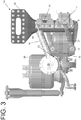
FIG. 3 illustrates a suspension system for a self-steering pusher or tag axle according to one embodiment. -
FIG. 4 illustrates a suspension system for a self-steering pusher or tag axle according to one embodiment. -
FIG. 5A illustrates a vehicle frame according to one embodiment. -
FIG. 5B illustrates a vehicle frame according to one embodiment. -
FIGS. 1-4 illustrate asuspension system 10 for a vehicle according to one embodiment. As shown, thesuspension system 10 of the present embodiment includes anaxle 15, opposing first and secondframe hanger brackets axle lift system 25, steeringstabilizers 35, first upper andlower control arms lower control arms - Those of ordinary skill in the art will appreciate that the first and second
frame hanger brackets vehicle frame members FIGS. 5A and B , of avehicle frame 5. Furthermore, those of ordinary skill in the art will appreciate that theaxle 15, has a lifted position 15c and a loweredposition 15d. Moreover, those of ordinary skill in the art will appreciate that theaxle lift system 25 lifts or lowers theaxle 15 in response to an increase in air pressure in loweringbladders 26 or liftingbladders 27, respectively. - Those of ordinary skill in the art will appreciate that
steering stabilizers 35 bias the wheels 7 (FIG. 5B ) in a substantially longitudinally forward direction, but allow the wheels to self-steer and turn while cornering when the biasing force of thesteering stabilizers 35 are exceeded by the tire turning forces. In the present embodiment, thesteering stabilizers 35 are advantageously adapted to provide improved forward bump steering biasing. As shown, thesteering stabilizers 35 are preferably provided withfirst ends 35a that are mounted fixed relative to thevehicle frame 5 and second ends 35b that are mounted to thesteering knuckles 7a and are moveable with theaxle 15, relative to thevehicle frame 5. As shown, by way of example, thesteering stabilizers 35 may have first ends 35a that are mounted to framehanger brackets steering stabilizers 35 may extend substantially perpendicular to theaxle 15. - According to one aspect of the present embodiment, the control arms 40-43 mount the
axle 15 to theframe hanger brackets lower control arms first end 15a of theaxle 15 along theframe 5 and the second upper andlower control arms second end 15b of theaxle 15 along theframe 5. - The first upper and
lower control arms first end 15a of theaxle 15 via a first upper pivotable axle joint 16 and a first lower pivotable axle joint 16', respectively. Also shown, the second upper andlower control arms second end 15b of theaxle 15 via a second upper pivotable axle joint 17 and a second lower pivotable axle joint 17', respectively. Furthermore, the first upper and lower pivotable axle joints 16 and 16' are substantially aligned with each other in lateral direction L and vertically spaced from each other in vertical direction V. Likewise, the second upper and lower pivotable axle joints 17 and 17' are substantially aligned with each other in the lateral direction L and vertically spaced from each other in the vertical direction V. As shown, the pivotable axle joints 16, 16', 17, 17' preferably lie on the same lateral plane; however in an alternative embodiment, the pivotable axle joints 16, 16', 17, 17' may lie on more than one plane. - As shown, the first upper and
lower control arms frame hanger bracket 20 at first upper and lower pivotable hanger joints 18 and 18', respectively. The second upper andlower control arms frame hanger bracket 21 at second upper and lower pivotable hanger joints 19 and 19', respectively. Furthermore, the first upper and lower pivotable hanger joints 18 and 18' are spaced with respect to each other in the lateral direction L and vertically spaced from each other in the vertical direction V. Likewise, the second upper and lower pivotable hanger joints 19 and 19' are spaced with respect to each other in the lateral direction L and vertically spaced from each other in the vertical direction V. As shown, the pivotable hanger joints 18, 18', 19, 19' preferably lie on the same lateral plane; however in an alternative embodiment, the pivotable hanger joints 18, 18', 19, 19' may lie on more than one plane. - Also shown, the first
frame hanger bracket 20 is preferably laterally interposed between the first upper and lower hanger joints 18, 18' so that the first upper pivotable hanger joint 18 is on one side of thefirst frame hanger 20 and the first lower pivotable hanger joint 18' is on an opposite side of thesecond frame hanger 21. Likewise, the secondframe hanger bracket 21 is laterally interposed between the second upper and lower hanger joints 18, 18' so that the second upper pivotable hanger joint 19 is on one side of thesecond frame hanger 21 and the second lower pivotable hanger joint 19' is on an opposite side of thesecond frame hanger 21. In alternative embodiments, thejoints 18, 18' may be located on the same side of thehangers - As shown best in
FIG. 1 , the first lower pivotable axle joint 16' and second lower pivotable axle joint 17' are longitudinally spaced from and located laterally inward with respect to the first and second lower pivotable hanger joints 18', 19', respectively. Also shown best inFIG. 1 , the first upper pivotable axle joint 16 and second upper pivotable axle joint 17 are longitudinally spaced from and located laterally outward with respect to the first and second upper pivotable hanger joints 18, 19, respectively. - As shown best in
FIG. 1 , the first upper andlower control arms FIG. 1 , the second upper andlower control arms lower control arms - The first upper and lower pivotable axle joints 16, 17 are preferably located on a longitudinal plane that passes through the lateral midpoint M between the first upper and lower pivotable hanger joints 18, 19, as shown in
FIG. 1 . Additionally, the second upper and lower pivotable axle joints 16', 17' are preferably located on a longitudinal plane that passes through the lateral midpoint M' between the second upper and lower pivotable hanger joints 18', 19', as shown inFIG. 1 . In alternative embodiments, the pivotable axle joints 16, 16', 17, 17' may be somewhat laterally off-set. - Advantageously, the
suspension system 10 allows larger articulations while maintaining the desired load on each wheel end. Thesuspension system 10 may be left in the loweredposition 15d while on the job site, without requiring a larger or heavier than needed rear suspension or requiring an operator to slow down to "creep rating". - Persons skilled in the art will recognize that certain elements of the above-described embodiments and examples may variously be combined or eliminated to create further embodiments, and such further embodiments fall within the scope and teachings of the invention. It will also be apparent to those of ordinary skill in the art that the above-described embodiments may be combined in whole or in part to create additional embodiments within the scope and teachings of the invention. Thus, although specific embodiments of, and examples for, the invention are described herein for illustrative purposes, various equivalent modifications are possible within the scope of the invention, as those skilled in the relevant art will recognize. Accordingly, the scope of the invention is determined from the appended claims and equivalents thereof.
- The present description depicts specific examples to teach those skilled in the art how to make and use the best mode of the invention. The detailed descriptions of the above embodiments are not exhaustive descriptions of all embodiments contemplated by the inventors to be within the scope of the invention. By way of example, and not limitation, a
tie rod 50 may interconnect steering knuckles at eachend axle 15 to improve steering characteristics in some embodiments. By way of another example, and not limitation, in alternative embodiments alternative lift systems may be employed, including, but not limited to non-pneumatic designs. - Persons skilled in the art will recognize that certain elements of the above-described embodiments may variously be combined or eliminated to create further embodiments, and such further embodiments fall within the scope and teachings of the invention. Thus, although specific embodiments of, and examples for, the invention are described herein for illustrative purposes, various equivalent modifications are possible within the scope of the invention, as those skilled in the relevant art will recognize. Accordingly, the scope of the invention is determined from the appended claims.
Claims (13)
- A suspension system (10) for a vehicle, comprising:a frame including opposing longitudinal vehicle frame members;an axle (15), including wheels, provided with a lifted position and a lowered position;opposing first (20) and second (21) frame hanger brackets mounted to the opposing longitudinal vehicle frame members;an axle lift system (25) adapted to lift or lower the axle (15);steering stabilizers (35) that are adapted to bias the wheels (7) in a substantially longitudinally forward direction;first upper (40) and lower (41) control arms that:longitudinally locate a first end (15a) of the axle (15) along the frame;include first ends pivotably mounted to the first end of the axle via a first upper pivotable axle joint (16) and a first lower pivotable axle joint (16'), respectively, wherein the first upper (16) and lower (16') pivotable axle joints are substantially aligned with each other in a lateral direction and vertically spaced from each other in a vertical direction; andsecond upper (42) and lower (43) control arms that:longitudinally locate a second end (15b) of the axle (15) along the frame;include first ends pivotably mounted to the second end of the axle at second upper pivotable axle joint (17) and a second lower pivotable axle joint (17'), respectively, wherein the second upper and lower pivotable axle joints are substantially aligned with each other in a lateral direction and vertically spaced from each other in a vertical direction;characterized in thatthe first upper (40) and lower (41) control arms:include second ends that are pivotably mounted to the first frame hanger bracket (20) via first upper (18) and lower (18') pivotable hanger joints, respectively, wherein the first upper and lower pivotable hanger joints are spaced with respect to each other in the lateral direction and vertically spaced from each other in the vertical direction;diverge, in opposite directions, laterally inward and outward, respectively, from the first upper and lower pivotable axle joints to the first upper and lower pivotable hanger joints; and thatthe second upper (42) and lower (43) control arms:include second ends that are pivotably mounted to the second frame hanger bracket via second upper (19) and lower (19') pivotable hanger joints, respectively, wherein the second upper and lower pivotable hanger joints are spaced with respect to each other in the lateral direction and vertically spaced from each other in the vertical direction; anddiverge, in opposite directions, laterally inward and outward, respectively, from the second upper and lower pivotable axle joints to the second upper and lower pivotable hanger joints.
- The suspension system for a vehicle according to claim 1, wherein all of the pivotable axle joints (16, 16', 17, 17') lie on the same lateral plane.
- The suspension system for a vehicle according to claim 1, wherein all of the pivotable hanger joints lie (18, 18', 19, 19') on the same lateral plane.
- The suspension system for a vehicle according to claim 1, wherein:all of the pivotable axle joints (16, 16', 17, 17') lie on the same lateral plane; andall of the pivotable hanger joints (18, 18', 19, 19') lie on the same lateral plane.
- The suspension system for a vehicle according to claim 1, wherein the first upper (40) and lower (41) control arms symmetrically diverge laterally inward and outward, respectively, from the first upper (16) and lower (16') pivotable axle joints to the first upper (18) and lower (18') pivotable hanger joints, respectively and the second upper and lower control arms symmetrically diverge laterally inward and outward, respectively, from the second upper and lower pivotable axle joints to the second upper and lower pivotable hanger joints, respectively.
- The suspension system for a vehicle according to claim 1, wherein:all of the pivotable axle joints (16, 16', 17, 17') lie on the same lateral plane;all of the pivotable hanger joints (18, 18', 19, 19') lie on the same lateral plane; andthe first upper (40) and lower (41) control arms symmetrically diverge laterally inward and outward, respectively, from the first upper and lower pivotable axle joints to the first upper and lower pivotable hanger joints, respectively and the second upper (42) and lower (43) control arms symmetrically diverge laterally inward and outward, respectively, from the second upper and lower pivotable axle joints to the second upper and lower pivotable hanger joints, respectively.
- The suspension system for a vehicle according to claim 1, wherein the first upper (16) and lower (16') pivotable axle joints are located on a longitudinal plane that passes through a lateral midpoint between the first upper (18) and lower (18') pivotable hanger joints and the second upper (17) and lower (17') pivotable axle joints are located on another longitudinal plane that passes through another lateral midpoint between the second upper (19) and lower (19') pivotable hanger joints.
- The suspension system for a vehicle according to claim 1, wherein:all of the pivotable axle joints (16, 16', 17, 17') lie on the same lateral plane;all of the pivotable hanger joints (18, 18', 19, 19') lie on the same lateral plane; andthe first upper and lower pivotable axle joints are located on a longitudinal plane that passes through a lateral midpoint between the first upper and lower pivotable hanger joints and the second upper and lower pivotable axle joints are located on another longitudinal plane that passes through another lateral midpoint between the second upper and lower pivotable hanger joints.
- The suspension system for a vehicle according to claim 1, wherein:all of the pivotable axle joints (16, 16', 17, 17') lie on the same lateral plane;all of the pivotable hanger joints (18, 18', 19, 19') lie on the same lateral plane;the first upper and lower control arms symmetrically diverge laterally inward and outward, respectively, from the first upper and lower pivotable axle joints to the first upper and lower pivotable hanger joints, respectively and the second upper and lower control arms symmetrically diverge laterally inward and outward, respectively, from the second upper and lower pivotable axle joints to the second upper and lower pivotable hanger joints, respectively; andthe first upper and lower pivotable axle joints are located on a longitudinal plane that passes through a lateral midpoint between the first upper and lower pivotable hanger joints and the second upper and lower pivotable axle joints are located on another longitudinal plane that passes through another lateral midpoint between the second upper and lower pivotable hanger joints.
- The suspension system for a vehicle according to claim 1, further comprising a tie rod (50) that interconnects steering knuckles located at each end of the axle (15).
- The suspension system for a vehicle according to claim 1, further comprising a tie rod that interconnects steering knuckles located at each end of the axle and wherein:all of the pivotable axle joints (16, 16', 17, 17') lie on the same lateral plane;all of the pivotable hanger joints (18, 18', 19, 19') lie on the same lateral plane;the first upper and lower control arms symmetrically diverge laterally inward and outward, respectively, from the first upper and lower pivotable axle joints to the first upper and lower pivotable hanger joints, respectively and the second upper and lower control arms symmetrically diverge laterally inward and outward, respectively, from the second upper and lower pivotable axle joints to the second upper and lower pivotable hanger joints, respectively; andthe first upper and lower pivotable axle joints are located on a longitudinal plane that passes through a lateral midpoint between the first upper and lower pivotable hanger joints and the second upper and lower pivotable axle joints are located on another longitudinal plane that passes through another lateral midpoint between the second upper and lower pivotable hanger joints.
- The suspension system for a vehicle according to claim 1, wherein:the first frame hanger bracket is laterally interposed between the first upper and lower hanger joints so that the first upper pivotable hanger joint is on one side of the first frame hanger and the first lower pivotable hanger joint is on an opposite side of the first frame hanger; andthe second frame hanger bracket is laterally interposed between the second upper and lower hanger joints so that the second upper pivotable hanger joint is on one side of the second frame hanger and the second lower pivotable hanger joint is on an opposite side of the second frame hanger.
- The suspension system for a vehicle according to claim 1, wherein the steering stabilizers are provided with first ends that are mounted fixed relative to the vehicle frame and second ends that are mounted to steering knuckles and moveable with the axle, relative to the vehicle frame.
Applications Claiming Priority (1)
| Application Number | Priority Date | Filing Date | Title |
|---|---|---|---|
| PCT/US2015/036370 WO2016204762A1 (en) | 2015-06-18 | 2015-06-18 | Liftable axle suspension |
Publications (3)
| Publication Number | Publication Date |
|---|---|
| EP3310643A1 EP3310643A1 (en) | 2018-04-25 |
| EP3310643A4 EP3310643A4 (en) | 2019-02-13 |
| EP3310643B1 true EP3310643B1 (en) | 2020-11-25 |
Family
ID=57545632
Family Applications (1)
| Application Number | Title | Priority Date | Filing Date |
|---|---|---|---|
| EP15895806.6A Not-in-force EP3310643B1 (en) | 2015-06-18 | 2015-06-18 | Liftable axle suspension |
Country Status (3)
| Country | Link |
|---|---|
| US (1) | US10427738B2 (en) |
| EP (1) | EP3310643B1 (en) |
| WO (1) | WO2016204762A1 (en) |
Families Citing this family (3)
| Publication number | Priority date | Publication date | Assignee | Title |
|---|---|---|---|---|
| US11712938B1 (en) | 2020-03-03 | 2023-08-01 | Jason M. Klein | Pistonless pneumatic dampening and straight centering for a steerable axle of a heavy-duty vehicle |
| US11794545B1 (en) | 2021-03-29 | 2023-10-24 | Jason M. Klein | Lift axle suspension system for a heavy-duty vehicle, which suspension system uses X-rod control arms for improved lateral stability |
| CN113119671B (en) * | 2021-04-15 | 2022-04-01 | 宿州德润机械有限公司 | All-terrain hydro-pneumatic spring liftable hydraulic suspension axle system |
Family Cites Families (10)
| Publication number | Priority date | Publication date | Assignee | Title |
|---|---|---|---|---|
| US5505481A (en) | 1994-03-07 | 1996-04-09 | Suspensions Incorporated | Lift axle suspension system |
| US5649719A (en) * | 1996-02-23 | 1997-07-22 | The Boler Company. | Linkage suspension system |
| CA2240791A1 (en) * | 1997-07-16 | 1999-01-16 | Neway Anchorlok International, Inc | Trailing arm suspension |
| US6135470A (en) * | 1998-06-01 | 2000-10-24 | The Boler Company | Transverse stabilizer for wheel axle suspension system |
| DE20023581U1 (en) * | 1999-03-06 | 2004-12-02 | Dr.Ing.H.C. F. Porsche Ag | Wheel suspension for driven rear wheels of a motor vehicle |
| US6398236B1 (en) * | 1999-07-16 | 2002-06-04 | Holland Neway International, Inc. | Lift axle suspension with axle reservoir |
| NZ538600A (en) | 2002-10-30 | 2007-10-26 | Hendrickson Internat Ltd | Steering damper and backup lock beam attachment |
| US6883813B2 (en) | 2003-02-26 | 2005-04-26 | The Boler Company | Independent paddle lift axle suspension system |
| WO2005039900A2 (en) * | 2003-10-24 | 2005-05-06 | Aloha, Llc | Suspensions for low floor vehicles |
| EP2917052B1 (en) * | 2012-11-07 | 2018-08-01 | Volvo Truck Corporation | Independent rear suspension with lifting device |
-
2015
- 2015-06-18 US US15/736,437 patent/US10427738B2/en active Active
- 2015-06-18 WO PCT/US2015/036370 patent/WO2016204762A1/en not_active Ceased
- 2015-06-18 EP EP15895806.6A patent/EP3310643B1/en not_active Not-in-force
Non-Patent Citations (1)
| Title |
|---|
| None * |
Also Published As
| Publication number | Publication date |
|---|---|
| US20180194412A1 (en) | 2018-07-12 |
| EP3310643A1 (en) | 2018-04-25 |
| EP3310643A4 (en) | 2019-02-13 |
| US10427738B2 (en) | 2019-10-01 |
| WO2016204762A1 (en) | 2016-12-22 |
Similar Documents
| Publication | Publication Date | Title |
|---|---|---|
| US9352628B2 (en) | Lift suspension system with offset control arms | |
| CN101557950B (en) | Wishbone-shaped link component and suspension system using the component | |
| US10569814B2 (en) | Lift axle auxiliary suspension systems | |
| EP2625050B1 (en) | Trailer for a trailer truck | |
| US20160129751A1 (en) | Coupled torsion beam axle type of suspension system | |
| US6942232B1 (en) | Suspension system for a transport vehicle | |
| EP3523180B1 (en) | Steering centering/damping mechanism for a steerable heavy-duty vehicle axle/suspension system | |
| US10427738B2 (en) | Liftable axle suspension | |
| RU2487018C2 (en) | Stabiliser system for wheel axle suspension, and stabiliser | |
| US6883813B2 (en) | Independent paddle lift axle suspension system | |
| US20150266507A1 (en) | Steering lock mechanism for heavy-duty vehicle axle/suspension system | |
| WO2018010799A1 (en) | Vehicle with steerable driven rear axle | |
| CN204451914U (en) | The superimposed trailer that suspension height is adjustable and transport trolley | |
| US20040056398A1 (en) | Stabilizer and air leaf suspension using the same | |
| US7562887B1 (en) | Self steering caster suspension system for a transport vehicle | |
| EP2990239B1 (en) | Semitrailer equipped with independent wheel suspension and air springs | |
| JP2009234518A (en) | Variable alignment angle vehicle | |
| WO2011069199A1 (en) | Heavy load trailer | |
| US20170203623A1 (en) | Wheel suspension device | |
| KR102417401B1 (en) | Stabilization control method using active roll stabilization and stabilization control system | |
| CN108608819B (en) | Trailer and suspension system thereof | |
| EP4261057B1 (en) | A leaf spring for use in a vehicle suspension | |
| JPH05193332A (en) | Vehicle steering angle / roll total control device | |
| KR20200084235A (en) | Auxiliary wheels lift device of truck | |
| JPH052552B2 (en) |
Legal Events
| Date | Code | Title | Description |
|---|---|---|---|
| STAA | Information on the status of an ep patent application or granted ep patent |
Free format text: STATUS: THE INTERNATIONAL PUBLICATION HAS BEEN MADE |
|
| PUAI | Public reference made under article 153(3) epc to a published international application that has entered the european phase |
Free format text: ORIGINAL CODE: 0009012 |
|
| STAA | Information on the status of an ep patent application or granted ep patent |
Free format text: STATUS: REQUEST FOR EXAMINATION WAS MADE |
|
| 17P | Request for examination filed |
Effective date: 20180116 |
|
| AK | Designated contracting states |
Kind code of ref document: A1 Designated state(s): AL AT BE BG CH CY CZ DE DK EE ES FI FR GB GR HR HU IE IS IT LI LT LU LV MC MK MT NL NO PL PT RO RS SE SI SK SM TR |
|
| AX | Request for extension of the european patent |
Extension state: BA ME |
|
| DAV | Request for validation of the european patent (deleted) | ||
| DAX | Request for extension of the european patent (deleted) | ||
| A4 | Supplementary search report drawn up and despatched |
Effective date: 20190115 |
|
| RIC1 | Information provided on ipc code assigned before grant |
Ipc: B60G 9/02 20060101ALI20190109BHEP Ipc: B60G 11/27 20060101ALI20190109BHEP Ipc: B62D 61/12 20060101AFI20190109BHEP |
|
| GRAP | Despatch of communication of intention to grant a patent |
Free format text: ORIGINAL CODE: EPIDOSNIGR1 |
|
| STAA | Information on the status of an ep patent application or granted ep patent |
Free format text: STATUS: GRANT OF PATENT IS INTENDED |
|
| INTG | Intention to grant announced |
Effective date: 20200612 |
|
| GRAS | Grant fee paid |
Free format text: ORIGINAL CODE: EPIDOSNIGR3 |
|
| GRAA | (expected) grant |
Free format text: ORIGINAL CODE: 0009210 |
|
| STAA | Information on the status of an ep patent application or granted ep patent |
Free format text: STATUS: THE PATENT HAS BEEN GRANTED |
|
| AK | Designated contracting states |
Kind code of ref document: B1 Designated state(s): AL AT BE BG CH CY CZ DE DK EE ES FI FR GB GR HR HU IE IS IT LI LT LU LV MC MK MT NL NO PL PT RO RS SE SI SK SM TR |
|
| REG | Reference to a national code |
Ref country code: GB Ref legal event code: FG4D |
|
| REG | Reference to a national code |
Ref country code: CH Ref legal event code: EP |
|
| REG | Reference to a national code |
Ref country code: AT Ref legal event code: REF Ref document number: 1337977 Country of ref document: AT Kind code of ref document: T Effective date: 20201215 |
|
| REG | Reference to a national code |
Ref country code: DE Ref legal event code: R096 Ref document number: 602015062753 Country of ref document: DE |
|
| REG | Reference to a national code |
Ref country code: IE Ref legal event code: FG4D |
|
| REG | Reference to a national code |
Ref country code: NL Ref legal event code: FP |
|
| REG | Reference to a national code |
Ref country code: AT Ref legal event code: MK05 Ref document number: 1337977 Country of ref document: AT Kind code of ref document: T Effective date: 20201125 |
|
| PG25 | Lapsed in a contracting state [announced via postgrant information from national office to epo] |
Ref country code: GR Free format text: LAPSE BECAUSE OF FAILURE TO SUBMIT A TRANSLATION OF THE DESCRIPTION OR TO PAY THE FEE WITHIN THE PRESCRIBED TIME-LIMIT Effective date: 20210226 Ref country code: RS Free format text: LAPSE BECAUSE OF FAILURE TO SUBMIT A TRANSLATION OF THE DESCRIPTION OR TO PAY THE FEE WITHIN THE PRESCRIBED TIME-LIMIT Effective date: 20201125 Ref country code: PT Free format text: LAPSE BECAUSE OF FAILURE TO SUBMIT A TRANSLATION OF THE DESCRIPTION OR TO PAY THE FEE WITHIN THE PRESCRIBED TIME-LIMIT Effective date: 20210325 Ref country code: FI Free format text: LAPSE BECAUSE OF FAILURE TO SUBMIT A TRANSLATION OF THE DESCRIPTION OR TO PAY THE FEE WITHIN THE PRESCRIBED TIME-LIMIT Effective date: 20201125 Ref country code: NO Free format text: LAPSE BECAUSE OF FAILURE TO SUBMIT A TRANSLATION OF THE DESCRIPTION OR TO PAY THE FEE WITHIN THE PRESCRIBED TIME-LIMIT Effective date: 20210225 |
|
| PG25 | Lapsed in a contracting state [announced via postgrant information from national office to epo] |
Ref country code: AT Free format text: LAPSE BECAUSE OF FAILURE TO SUBMIT A TRANSLATION OF THE DESCRIPTION OR TO PAY THE FEE WITHIN THE PRESCRIBED TIME-LIMIT Effective date: 20201125 Ref country code: PL Free format text: LAPSE BECAUSE OF FAILURE TO SUBMIT A TRANSLATION OF THE DESCRIPTION OR TO PAY THE FEE WITHIN THE PRESCRIBED TIME-LIMIT Effective date: 20201125 Ref country code: LV Free format text: LAPSE BECAUSE OF FAILURE TO SUBMIT A TRANSLATION OF THE DESCRIPTION OR TO PAY THE FEE WITHIN THE PRESCRIBED TIME-LIMIT Effective date: 20201125 Ref country code: IS Free format text: LAPSE BECAUSE OF FAILURE TO SUBMIT A TRANSLATION OF THE DESCRIPTION OR TO PAY THE FEE WITHIN THE PRESCRIBED TIME-LIMIT Effective date: 20210325 Ref country code: BG Free format text: LAPSE BECAUSE OF FAILURE TO SUBMIT A TRANSLATION OF THE DESCRIPTION OR TO PAY THE FEE WITHIN THE PRESCRIBED TIME-LIMIT Effective date: 20210225 |
|
| REG | Reference to a national code |
Ref country code: LT Ref legal event code: MG9D |
|
| PG25 | Lapsed in a contracting state [announced via postgrant information from national office to epo] |
Ref country code: HR Free format text: LAPSE BECAUSE OF FAILURE TO SUBMIT A TRANSLATION OF THE DESCRIPTION OR TO PAY THE FEE WITHIN THE PRESCRIBED TIME-LIMIT Effective date: 20201125 |
|
| PG25 | Lapsed in a contracting state [announced via postgrant information from national office to epo] |
Ref country code: SM Free format text: LAPSE BECAUSE OF FAILURE TO SUBMIT A TRANSLATION OF THE DESCRIPTION OR TO PAY THE FEE WITHIN THE PRESCRIBED TIME-LIMIT Effective date: 20201125 Ref country code: LT Free format text: LAPSE BECAUSE OF FAILURE TO SUBMIT A TRANSLATION OF THE DESCRIPTION OR TO PAY THE FEE WITHIN THE PRESCRIBED TIME-LIMIT Effective date: 20201125 Ref country code: EE Free format text: LAPSE BECAUSE OF FAILURE TO SUBMIT A TRANSLATION OF THE DESCRIPTION OR TO PAY THE FEE WITHIN THE PRESCRIBED TIME-LIMIT Effective date: 20201125 Ref country code: CZ Free format text: LAPSE BECAUSE OF FAILURE TO SUBMIT A TRANSLATION OF THE DESCRIPTION OR TO PAY THE FEE WITHIN THE PRESCRIBED TIME-LIMIT Effective date: 20201125 Ref country code: RO Free format text: LAPSE BECAUSE OF FAILURE TO SUBMIT A TRANSLATION OF THE DESCRIPTION OR TO PAY THE FEE WITHIN THE PRESCRIBED TIME-LIMIT Effective date: 20201125 Ref country code: SK Free format text: LAPSE BECAUSE OF FAILURE TO SUBMIT A TRANSLATION OF THE DESCRIPTION OR TO PAY THE FEE WITHIN THE PRESCRIBED TIME-LIMIT Effective date: 20201125 |
|
| REG | Reference to a national code |
Ref country code: DE Ref legal event code: R097 Ref document number: 602015062753 Country of ref document: DE |
|
| PG25 | Lapsed in a contracting state [announced via postgrant information from national office to epo] |
Ref country code: DK Free format text: LAPSE BECAUSE OF FAILURE TO SUBMIT A TRANSLATION OF THE DESCRIPTION OR TO PAY THE FEE WITHIN THE PRESCRIBED TIME-LIMIT Effective date: 20201125 |
|
| PLBE | No opposition filed within time limit |
Free format text: ORIGINAL CODE: 0009261 |
|
| STAA | Information on the status of an ep patent application or granted ep patent |
Free format text: STATUS: NO OPPOSITION FILED WITHIN TIME LIMIT |
|
| PG25 | Lapsed in a contracting state [announced via postgrant information from national office to epo] |
Ref country code: AL Free format text: LAPSE BECAUSE OF FAILURE TO SUBMIT A TRANSLATION OF THE DESCRIPTION OR TO PAY THE FEE WITHIN THE PRESCRIBED TIME-LIMIT Effective date: 20201125 Ref country code: IT Free format text: LAPSE BECAUSE OF FAILURE TO SUBMIT A TRANSLATION OF THE DESCRIPTION OR TO PAY THE FEE WITHIN THE PRESCRIBED TIME-LIMIT Effective date: 20201125 |
|
| 26N | No opposition filed |
Effective date: 20210826 |
|
| PG25 | Lapsed in a contracting state [announced via postgrant information from national office to epo] |
Ref country code: SI Free format text: LAPSE BECAUSE OF FAILURE TO SUBMIT A TRANSLATION OF THE DESCRIPTION OR TO PAY THE FEE WITHIN THE PRESCRIBED TIME-LIMIT Effective date: 20201125 |
|
| PG25 | Lapsed in a contracting state [announced via postgrant information from national office to epo] |
Ref country code: MC Free format text: LAPSE BECAUSE OF FAILURE TO SUBMIT A TRANSLATION OF THE DESCRIPTION OR TO PAY THE FEE WITHIN THE PRESCRIBED TIME-LIMIT Effective date: 20201125 Ref country code: ES Free format text: LAPSE BECAUSE OF FAILURE TO SUBMIT A TRANSLATION OF THE DESCRIPTION OR TO PAY THE FEE WITHIN THE PRESCRIBED TIME-LIMIT Effective date: 20201125 |
|
| REG | Reference to a national code |
Ref country code: CH Ref legal event code: PL |
|
| GBPC | Gb: european patent ceased through non-payment of renewal fee |
Effective date: 20210618 |
|
| REG | Reference to a national code |
Ref country code: BE Ref legal event code: MM Effective date: 20210630 |
|
| PG25 | Lapsed in a contracting state [announced via postgrant information from national office to epo] |
Ref country code: LU Free format text: LAPSE BECAUSE OF NON-PAYMENT OF DUE FEES Effective date: 20210618 |
|
| PG25 | Lapsed in a contracting state [announced via postgrant information from national office to epo] |
Ref country code: LI Free format text: LAPSE BECAUSE OF NON-PAYMENT OF DUE FEES Effective date: 20210630 Ref country code: IE Free format text: LAPSE BECAUSE OF NON-PAYMENT OF DUE FEES Effective date: 20210618 Ref country code: GB Free format text: LAPSE BECAUSE OF NON-PAYMENT OF DUE FEES Effective date: 20210618 Ref country code: CH Free format text: LAPSE BECAUSE OF NON-PAYMENT OF DUE FEES Effective date: 20210630 |
|
| PG25 | Lapsed in a contracting state [announced via postgrant information from national office to epo] |
Ref country code: IS Free format text: LAPSE BECAUSE OF FAILURE TO SUBMIT A TRANSLATION OF THE DESCRIPTION OR TO PAY THE FEE WITHIN THE PRESCRIBED TIME-LIMIT Effective date: 20210325 |
|
| PG25 | Lapsed in a contracting state [announced via postgrant information from national office to epo] |
Ref country code: BE Free format text: LAPSE BECAUSE OF NON-PAYMENT OF DUE FEES Effective date: 20210630 |
|
| PG25 | Lapsed in a contracting state [announced via postgrant information from national office to epo] |
Ref country code: CY Free format text: LAPSE BECAUSE OF FAILURE TO SUBMIT A TRANSLATION OF THE DESCRIPTION OR TO PAY THE FEE WITHIN THE PRESCRIBED TIME-LIMIT Effective date: 20201125 |
|
| PG25 | Lapsed in a contracting state [announced via postgrant information from national office to epo] |
Ref country code: HU Free format text: LAPSE BECAUSE OF FAILURE TO SUBMIT A TRANSLATION OF THE DESCRIPTION OR TO PAY THE FEE WITHIN THE PRESCRIBED TIME-LIMIT; INVALID AB INITIO Effective date: 20150618 |
|
| PG25 | Lapsed in a contracting state [announced via postgrant information from national office to epo] |
Ref country code: MK Free format text: LAPSE BECAUSE OF FAILURE TO SUBMIT A TRANSLATION OF THE DESCRIPTION OR TO PAY THE FEE WITHIN THE PRESCRIBED TIME-LIMIT Effective date: 20201125 |
|
| PGFP | Annual fee paid to national office [announced via postgrant information from national office to epo] |
Ref country code: DE Payment date: 20240627 Year of fee payment: 10 |
|
| PGFP | Annual fee paid to national office [announced via postgrant information from national office to epo] |
Ref country code: NL Payment date: 20240625 Year of fee payment: 10 |
|
| PGFP | Annual fee paid to national office [announced via postgrant information from national office to epo] |
Ref country code: FR Payment date: 20240625 Year of fee payment: 10 |
|
| PGFP | Annual fee paid to national office [announced via postgrant information from national office to epo] |
Ref country code: SE Payment date: 20240624 Year of fee payment: 10 |
|
| PG25 | Lapsed in a contracting state [announced via postgrant information from national office to epo] |
Ref country code: MT Free format text: LAPSE BECAUSE OF FAILURE TO SUBMIT A TRANSLATION OF THE DESCRIPTION OR TO PAY THE FEE WITHIN THE PRESCRIBED TIME-LIMIT Effective date: 20201125 |
|
| PG25 | Lapsed in a contracting state [announced via postgrant information from national office to epo] |
Ref country code: TR Free format text: LAPSE BECAUSE OF FAILURE TO SUBMIT A TRANSLATION OF THE DESCRIPTION OR TO PAY THE FEE WITHIN THE PRESCRIBED TIME-LIMIT Effective date: 20201125 |
|
| REG | Reference to a national code |
Ref country code: DE Ref legal event code: R119 Ref document number: 602015062753 Country of ref document: DE |
|
| REG | Reference to a national code |
Ref country code: SE Ref legal event code: EUG |
|
| REG | Reference to a national code |
Ref country code: NL Ref legal event code: MM Effective date: 20250701 |
|
| PG25 | Lapsed in a contracting state [announced via postgrant information from national office to epo] |
Ref country code: NL Free format text: LAPSE BECAUSE OF NON-PAYMENT OF DUE FEES Effective date: 20250701 |
|
| PG25 | Lapsed in a contracting state [announced via postgrant information from national office to epo] |
Ref country code: DE Free format text: LAPSE BECAUSE OF NON-PAYMENT OF DUE FEES Effective date: 20260101 |
|
| PG25 | Lapsed in a contracting state [announced via postgrant information from national office to epo] |
Ref country code: FR Free format text: LAPSE BECAUSE OF NON-PAYMENT OF DUE FEES Effective date: 20250630 |