EP3310144A1 - Jet impingement immersion cooling with synthetic ejector - Google Patents
Jet impingement immersion cooling with synthetic ejector Download PDFInfo
- Publication number
- EP3310144A1 EP3310144A1 EP17196115.4A EP17196115A EP3310144A1 EP 3310144 A1 EP3310144 A1 EP 3310144A1 EP 17196115 A EP17196115 A EP 17196115A EP 3310144 A1 EP3310144 A1 EP 3310144A1
- Authority
- EP
- European Patent Office
- Prior art keywords
- integrated circuit
- lru
- cooling fluid
- synthetic jet
- ejector
- Prior art date
- Legal status (The legal status is an assumption and is not a legal conclusion. Google has not performed a legal analysis and makes no representation as to the accuracy of the status listed.)
- Withdrawn
Links
- 238000007654 immersion Methods 0.000 title claims abstract description 78
- 238000001816 cooling Methods 0.000 title claims abstract description 43
- 239000012809 cooling fluid Substances 0.000 claims abstract description 72
- 238000000034 method Methods 0.000 claims abstract description 17
- 239000012530 fluid Substances 0.000 claims description 42
- 230000010355 oscillation Effects 0.000 claims description 16
- 230000004907 flux Effects 0.000 claims description 9
- 230000009977 dual effect Effects 0.000 claims description 6
- 230000017525 heat dissipation Effects 0.000 description 4
- 230000004075 alteration Effects 0.000 description 2
- 238000004590 computer program Methods 0.000 description 2
- 238000005516 engineering process Methods 0.000 description 2
- 239000007788 liquid Substances 0.000 description 2
- 238000012986 modification Methods 0.000 description 2
- 230000004048 modification Effects 0.000 description 2
- 238000009835 boiling Methods 0.000 description 1
- 239000002826 coolant Substances 0.000 description 1
- 229910052500 inorganic mineral Inorganic materials 0.000 description 1
- 230000010354 integration Effects 0.000 description 1
- 239000000463 material Substances 0.000 description 1
- 238000005259 measurement Methods 0.000 description 1
- 239000011707 mineral Substances 0.000 description 1
- 230000002250 progressing effect Effects 0.000 description 1
- 238000006467 substitution reaction Methods 0.000 description 1
Images






Classifications
-
- H—ELECTRICITY
- H05—ELECTRIC TECHNIQUES NOT OTHERWISE PROVIDED FOR
- H05K—PRINTED CIRCUITS; CASINGS OR CONSTRUCTIONAL DETAILS OF ELECTRIC APPARATUS; MANUFACTURE OF ASSEMBLAGES OF ELECTRICAL COMPONENTS
- H05K7/00—Constructional details common to different types of electric apparatus
- H05K7/20—Modifications to facilitate cooling, ventilating, or heating
- H05K7/20218—Modifications to facilitate cooling, ventilating, or heating using a liquid coolant without phase change in electronic enclosures
- H05K7/20236—Modifications to facilitate cooling, ventilating, or heating using a liquid coolant without phase change in electronic enclosures by immersion
-
- H—ELECTRICITY
- H05—ELECTRIC TECHNIQUES NOT OTHERWISE PROVIDED FOR
- H05K—PRINTED CIRCUITS; CASINGS OR CONSTRUCTIONAL DETAILS OF ELECTRIC APPARATUS; MANUFACTURE OF ASSEMBLAGES OF ELECTRICAL COMPONENTS
- H05K7/00—Constructional details common to different types of electric apparatus
- H05K7/20—Modifications to facilitate cooling, ventilating, or heating
- H05K7/20218—Modifications to facilitate cooling, ventilating, or heating using a liquid coolant without phase change in electronic enclosures
- H05K7/20272—Accessories for moving fluid, for expanding fluid, for connecting fluid conduits, for distributing fluid, for removing gas or for preventing leakage, e.g. pumps, tanks or manifolds
-
- H—ELECTRICITY
- H05—ELECTRIC TECHNIQUES NOT OTHERWISE PROVIDED FOR
- H05K—PRINTED CIRCUITS; CASINGS OR CONSTRUCTIONAL DETAILS OF ELECTRIC APPARATUS; MANUFACTURE OF ASSEMBLAGES OF ELECTRICAL COMPONENTS
- H05K7/00—Constructional details common to different types of electric apparatus
- H05K7/20—Modifications to facilitate cooling, ventilating, or heating
- H05K7/20218—Modifications to facilitate cooling, ventilating, or heating using a liquid coolant without phase change in electronic enclosures
- H05K7/20281—Thermal management, e.g. liquid flow control
Definitions
- the subject matter disclosed herein generally relates to component cooling and, more particularly, to cooling an integrated circuit using immersion cooling along with other elements.
- Immersion cooling is steadily progressing as a thermal management technology for high heat flux applications.
- Immersion cooling is a cooling practice by which components are submerged in a thermally but not electrically conductive liquid.
- the coolant liquid is commonly mineral-based oil with dielectric properties.
- a limiting factor in this technology is the critical heat flux that can be obtained and the surface super heat from a given device.
- an immersion cooled line replaceable unit (LRU) with jet impingement immersion cooling includes an integrated circuit disposed in the immersion cooled LRU, and a synthetic jet ejector disposed in the immersion cooled LRU, wherein the synthetic jet ejector creates a submerged jet impingement flow of cooling fluid toward the integrated circuit.
- further embodiments may include, wherein the integrated circuit is a high heat flux device.
- further embodiments may include, wherein the integrated circuit is an insulated-gate bipolar transistor (IGBT) die.
- IGBT insulated-gate bipolar transistor
- further embodiments may include, wherein the synthetic jet ejector includes a cavity with an opening that faces toward the integrated circuit, a piezoelectric baffle that oscillates in the cavity creating a high velocity flow area of cooling fluid toward the integrated circuit.
- further embodiments may include, wherein the piezoelectric baffle further oscillates in the cavity creating the high velocity flow area that entrains the surrounding fluid to create the submerged jet impingement flow of cooling fluid.
- further embodiments may include, wherein the synthetic jet ejector is adjacent to the integrated circuit such that the opening of the cavity of the synthetic jet ejector faces the integrated circuit, and wherein the submerged jet impingement flow of cooling fluid impinges onto the integrated circuit.
- further embodiments may include a plurality of synthetic jet ejectors disposed in the immersion cooled LRU, wherein each of the plurality of synthetic jet ejectors direct a submerged jet impingement flow of cooling fluid toward the integrated circuit.
- further embodiments may include a plurality of integrated circuits disposed in the immersion cooled LRU, wherein the plurality of integrated circuits are mounted on one or more inner surfaces of the immersion cooled LRU.
- further embodiments may include, wherein the plurality of synthetic jet ejectors are arranged in a pattern along a plane parallel to a surface plane of the integrated circuit.
- further embodiments may include, wherein the plurality of synthetic jet ejectors are arranged such that each of the ejectors are placed over a high heat point of the integrated circuit.
- further embodiments may include a second integrated circuit disposed in the immersion cooled LRU, wherein the second integrated circuit is mounted on a second inner surface opposite the integrated circuit mounted on a first inner surface, and a second synthetic jet ejector disposed in the immersion cooled LRU adjacent to the synthetic jet ejector, wherein the second synthetic jet ejector creates a second submerged jet impingement flow of cooling fluid toward the integrated circuit and the second integrated circuit as the second synthetic jet ejector oscillates, and wherein the synthetic jet ejector creates the submerged jet impingement flow of cooling fluid toward the integrated circuit and the second integrated circuit as the synthetic jet ejector oscillates.
- further embodiments may include, wherein the synthetic jet ejector is a dual opening ejector including a cavity with a first opening that faces toward the integrated circuit and a second opening that faces toward the second integrated circuit, and a piezoelectric baffle disposed between the first opening and the second opening in the cavity, wherein the piezoelectric baffle oscillates in the cavity creating a first high velocity flow area of cooling fluid toward the integrated circuit in a first direction of oscillation and a second high velocity flow area of cooling fluid toward the second integrated circuit in a second direction of oscillation.
- further embodiments may include, wherein the second synthetic jet ejector is a second dual opening ejector including a second cavity with a third opening that faces toward the integrated circuit and a fourth opening that faces toward the second integrated circuit, and a second piezoelectric baffle disposed between the third opening and the fourth opening in the second cavity, wherein the second piezoelectric baffle oscillates in the second cavity creating a third high velocity flow area of cooling fluid toward the integrated circuit in the first direction of oscillation and a fourth high velocity flow area of cooling fluid toward the second integrated circuit in the second direction of oscillation.
- further embodiments may include, wherein the piezoelectric baffle and the second piezoelectric baffle oscillate in an alternating pattern 180 degrees out of phase.
- further embodiments may include, wherein the piezoelectric baffle and the second piezoelectric baffle oscillate in phase.
- a computer implemented method for cooling an integrated circuit using immersion cooling includes receiving, at a controller, system information, generating, using the controller, a control signal based on the system information, creating, using a synthetic jet ejector, a submerged jet impingement flow of cooling fluid toward the integrated circuit based on the control signal, and impinging the jet impingement flow onto the integrated circuit surface.
- further embodiments may include, creating a high velocity flow area that entrains the surrounding cooling fluid to create the submerged jet impingement flow of cooling fluid toward the integrated circuit.
- further embodiments may include, generating, using the controller, a plurality of control signals based on the system information for controlling a plurality of synthetic jet ejectors, and creating, using the plurality of synthetic jet ejectors, a plurality of submerged jet impingement flows toward different points of the integrated circuit that correspond with the placement of the plurality of synthetic jet ejectors.
- system information includes one or more from a group consisting of sensor signals, temperature signals, user input, historic usage information, other system usage records, user specified operations, and user specified boundaries.
- a computer program product for jet impingement immersion cooling includes a computer readable storage medium having program instructions embodied therewith, the program instructions executable by a processor to cause the processor to receive, at a controller, system information, generate, using the controller, a control signal based on the system information, create, using a synthetic jet ejector, a submerged jet impingement flow of cooling fluid toward the integrated circuit based on the control signal, and impinge the jet impingement flow onto the integrated circuit surface.
- Embodiments described herein are directed to the integration of one or more synthetic jet ejectors within an immersion cooled line replaceable unit (LRU).
- one or more embodiments add one or more synthetic ejectors to create submerged jet impingement cooling of high heat flux devices such as integrated circuits (for example, an insulated-gate bipolar transistor (IGBT) die) in an immersion cooled LRU.
- the one or more synthetic ejectors consist of a piezoelectric baffle which oscillates in a cavity with a small opening. The oscillation of the baffle creates a high velocity flow area which then entrains the surrounding fluid to create the submerged jet.
- the ejectors are located such that the jet that is created impinges directly onto the high heat flux device surface.
- the ejectors may be distributed with greater number in an area to correspond to areas of greater heat flux.
- the immersion cooled LRU 100 includes integrated circuit 120, which can also be referred to as a die 120, and a fluid ejector 110 in a housing 130 in accordance with one or more embodiments.
- the immersion cooled LRU 100 includes a cooling fluid 135 that can be a dielectric cooling fluid 135 that fill the internal cavity of the housing 130 of the immersion cooled LRU 100.
- the cooling fluid is non-conductive and is designed to transfer heat.
- the integrated circuit 120 is provided within the housing such that the integrated circuit 120 is submerged in the cooling fluid 135.
- the synthetic jet ejector 110 is provided in the housing 130 such that it is also submerged in the cooling fluid 135. Further, as shown, the synthetic jet ejector 110 is positioned such that it can create a submerged jet impingement flow of cooling fluid 137 toward the integrated circuit 120.
- FIG. 2A is an illustration of a side view of an immersion cooling system 200A that includes a plurality of integrated circuits or die 120 and 121 and fluid ejectors 110 and 111 in a housing 130 in accordance with one or more embodiments.
- the housing 130 is a fully enclosed fixture that is filled with cooling fluid 135.
- the integrated circuits 120 and 121 are mounted on inner surfaces of the housing 130 as shown. Accordingly the integrated circuits 120 and 121 can connect with other circuits and/or wires to receive and transmit signals using the surface of the integrated circuits 120 and 121 that is mounted to the housing 130. Further the other surfaces of the integrated circuits 120 and 121 remain submerged in the cooling fluid 135.
- the synthetic jet ejectors 110 and 111 are provided in the housing 130 such that they are also submerged in the cooling fluid 135. Further, as shown, the synthetic jet ejectors 110 and 111 are positioned such that they can each create a submerged jet impingement flow of cooling fluid 135 toward a respective integrated circuit 120 and 121. Specifically, synthetic jet ejector 110 creates a submerged jet impingement flow 237 of cooling fluid 135 toward the integrated circuit 120. Further, the synthetic jet ejector 111 creates a submerged jet impingement flow 238 of cooling fluid 135 toward the integrated circuit 121. Accordingly the cooling fluid 135 is moved along the integrated circuits' 120 and 121 surfaces which can improve heat dissipation.
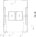
- FIG. 2B is an illustration of a side view of an immersion cooling system 200B that includes a plurality of integrated circuits 120 and 121 and fluid ejectors 110 and 111 in a housing 130 with openings 131 and 132 forming a passage in accordance with one or more embodiments.
- the housing 130 has a first opening 131 on a surface perpendicular to either of the surfaces upon which the integrated circuits 120 and 121 are mounted.
- the housing also has a second opening 132 on a surface opposite the first opening 131. Accordingly a passage is provided that extends through the housing 130 from the first opening 131 to the second opening 132. Accordingly, a flow of cooling fluid can be provided through the immersion cooling system 200B.
- the synthetic jet ejectors 110 and 111 can be used to increase the amount and velocity of cooling fluid that comes in contact with the surfaces of the integrated circuits 120 and 121.
- the integrated circuits 120 and 121 are mounted on different inner surfaces of the housing 130 as shown. Accordingly the integrated circuits 120 and 121 can connect with other circuits and/or wires to receive and transmit signals using the surface of the integrated circuits 120 and 121 that is mounted to the housing 130. Further the other surfaces of the integrated 120 and 121 remain submerged in the cooling fluid.
- the synthetic jet ejectors 110, 111, 112, and 113 are provided in the housing 130 such that they are also submerged in the cooling fluid.
- the synthetic jet ejectors 110 and 111 are positioned such that they can each create a submerged jet impingement flow of cooling fluid toward a respective integrated circuit 120 and 121.
- synthetic jet ejector 110 creates a submerged jet impingement flow of cooling fluid toward the integrated circuit 120.
- the synthetic jet ejector 111 creates a submerged jet impingement flow of cooling fluid toward the integrated circuit 121.
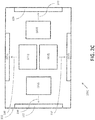
- FIG. 2C is an illustration of a side view of an immersion cooling system 200C that includes a plurality of integrated circuits 120, 121, 122, and 123 and fluid ejectors 110, 111, 112, and 113 in a housing 130 in accordance with one or more embodiments.
- the housing 130 is a fully enclosed fixture that is filled with cooling fluid.
- the integrated circuits 120, 121, 122, and 123 are mounted on inner surfaces of the housing 130 as shown. Accordingly the integrated circuits 120, 121, 122, and 123 can connect with other circuits and/or wires to receive and transmit signals using the surface of the integrated circuits 120, 121, 122, and 123 that is mounted to the housing 130.
- the other surfaces of the integrated circuits 120, 121, 122, and 123 remain submerged in the cooling fluid 135.
- the synthetic jet ejectors 110, 111, 112, and 113 are provided in the housing 130 such that they are also submerged in the cooling fluid 135.
- the synthetic jet ejectors 110, 111, 112, and 113 are positioned such that they can each create a submerged jet impingement flow of cooling fluid 135 toward a respective integrated circuit 120, 121, 122, and 123.
- synthetic jet ejector 110 creates a submerged jet impingement flow 237 of cooling fluid 135 toward the integrated circuit 120.
- the synthetic jet ejector 111 creates a submerged jet impingement flow 238 of cooling fluid 135 toward the integrated circuit 121. Accordingly the cooling fluid 135 is moved along the integrated circuits' 120 and 121 surfaces that can improve heat dissipation.
- the synthetic jet ejector 112 creates a submerged jet impingement flow 239 of cooling fluid toward the integrated circuit 122 and synthetic jet ejector 113 creates a submerged jet impingement flow 240 of cooling fluid toward the integrated circuit 123. Accordingly the cooling fluid is moved along the integrated circuits' 122 and 123 surfaces which can improve heat dissipation.
- FIG. 3 A is an illustration of a side view of an immersion cooling system 300A that includes a die 320, which can also be called an integrated circuit, on a baseplate 330 and a fluid ejector 310 in accordance with one or more embodiments.
- the fluid ejector 310 includes a housing 310.3 that is formed with a cavity 310.2.
- the housing 310.3 also includes an opening that faces toward the die 320.
- the fluid ejector 310 further includes a piezoelectric baffle 310.1 that oscillates in the cavity 310.2 creating a high velocity flow area 350 of cooling fluid toward the die 320.
- FIG. 3B is an illustration of a side view of an immersion cooling system that includes a die 320 on a baseplate 330 and a fluid ejector 310 spaced apart from the die 320 in accordance with one or more embodiments.
- the piezoelectric baffle of the fluid ejector 310 can oscillate in the cavity creating a high velocity flow area 350 of cooling fluid toward the die 320.
- the piezoelectric baffle oscillates in the cavity creating the high velocity flow area 350 that entrains the surrounding fluid 351 and 352 to create the submerged jet impingement flow of cooling fluid.
- FIG. 4 is an illustration of a side view of an immersion cooling system 400, also called an immersion cooled LRU 400, which includes a plurality of die 420 and 421 on corresponding baseplates 430 and 431 and a plurality of fluid ejectors 410 and 411 in accordance with one or more embodiments.
- the plurality of fluid ejectors includes a first synthetic jet ejector 410 and as second synthetic jet ejector 411.
- the plurality of die includes a first integrated circuit 420 and second integrated circuit 421.
- the first integrated circuit 420 and second integrated circuit 421 are provided in the immersion cooled LRU 400.
- the second integrated circuit 421 is mounted on a second inner surface 431 opposite the first integrated circuit 420 mounted on a first inner surface 430.
- the second synthetic jet ejector 411 is disposed in the immersion cooled LRU adjacent to the synthetic jet ejector 410.
- the first synthetic jet ejector 410 is a dual opening ejector that includes a cavity with a first opening that faces toward the integrated circuit 420 and a second opening that faces toward the second integrated circuit 421.
- the first synthetic jet ejector 410 also includes a first piezoelectric baffle 410.1 disposed between the first opening and the second opening in the cavity.
- the piezoelectric baffle 410.1 oscillates in the cavity creating a first high velocity flow area 450 of cooling fluid toward the first integrated circuit 420 in a first direction of oscillation and can create a second high velocity flow area of cooling fluid toward the second integrated circuit 421 in a second direction of oscillation when the piezoelectric baffle 410.1 oscillates the other direction.
- the second synthetic jet ejector 411 is a second dual opening ejector that includes a second cavity with a third opening that faces toward the first integrated circuit 420 and a fourth opening that faces toward the second integrated circuit 421.
- the synthetic jet ejector 411 also includes a second piezoelectric baffle 411.1 disposed between the third opening and the fourth opening in the second cavity.
- the second piezoelectric baffle 411.1 oscillates in the second cavity creating a third high velocity flow 451 area of cooling fluid toward the second integrated circuit 421 in the second direction of oscillation and can create a fourth high velocity flow area of cooling fluid toward the first integrated circuit 420 in the first direction of oscillation.
- FIG. 5 is an illustration of a top view of an immersion cooling system 500 that includes a die 520 and a plurality of fluid ejectors 501, 502, 503, and 504 in accordance with one or more embodiments.
- the fluid ejectors 501, 502, 503, and 504 are evenly arranged over the die 520.
- the fluid ejectors 501, 502, 503, and 504 can oscillate a plurality of different ways to move cooling fluid toward the die.
- the fluid ejectors 501, 502, 503, and 504 can oscillate in unison, or said another way, the fluid ejectors 501, 502, 503, and 504 can oscillate in phase with the same frequency.
- each fluid ejector 501, 502, 503, and 504 can be adjusted too such that they are each the same or different according to the specific heat dissipation requirements of the die 520.
- the frequency of oscillation of each fluid ejector 501, 502, 503, and 504 can be the same, different, or any combination thereof.
- the fluid ejectors 501 and 504 can oscillate 180 degrees out of phase as compared to fluid ejectors 502 and 503.
- Other oscillation patterns can also be provided such as oscillating fluid ejectors 501, 502, 503, and 504 in a clockwise or counterclockwise pattern.
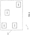
- FIG. 6 is an illustration of a top view of an immersion cooling system 600 that includes a die 620 and a plurality of fluid ejectors 601, 602, 603, and 604 placed over select heat points in accordance with one or more embodiments.
- the fluid ejectors 601, 602, 603, and 604 can similarly oscillate in a number of different ways as described above with references to FIG. 5 .
- FIG. 7 is an illustration of a top view of an immersion cooling system 700 that includes a die 720 and a plurality of fluid ejectors 701, 702, 703, 704, 705, 706, 707, and 708 evenly spaced apart in a pattern in accordance with one or more embodiments.
- other geometric patterns can be provided for placing the fluid ejectors 701, 702, 703, 704, 705, 706, 707, and 708 as well as the number of fluid ejectors 701, 702, 703, 704, 705, 706, 707, and 708 can be adjusted.
- the integrated circuit is a high heat flux device. According to one or more embodiments, the integrated circuit is an insulated-gate bipolar transistor (IGBT) die.
- IGBT insulated-gate bipolar transistor
- the synthetic jet ejector is adjacent to the integrated circuit such that the opening of the cavity of the synthetic jet ejector faces the integrated circuit.
- the submerged jet impingement flow of cooling fluid impinges onto the integrated circuit.
- the plurality of synthetic jet ejectors are arranged in a pattern along a plane parallel to a surface plane of the integrated circuit. According to one or more embodiments, the plurality of synthetic jet ejectors are arranged such that each of the ejectors are placed over a high heat point of the integrated circuit.
- FIG. 8 is a flow chart of a method 800 of immersion cooling using at least one fluid ejector in accordance with one or more embodiments.
- the method 800 includes receiving, at a controller, system information (operation 805).
- the method 800 further includes generating, using the controller, a control signal based on the system information (operation 810).
- the method 800 also includes creating, using a synthetic jet ejector, a submerged jet impingement flow of cooling fluid toward the integrated circuit based on the control signal (operation 815). Further, the method 800 includes impinging the jet impingement flow onto the integrated circuit surface (operation 820).
- the method can further include creating a high velocity flow area that entrains the surrounding cooling fluid to create the submerged jet impingement flow of cooling fluid toward the integrated circuit.
- the method can further include generating, using the controller, a plurality of control signals based on the system information for controlling a plurality of synthetic jet ejectors.
- the method can further include creating, using the plurality of synthetic jet ejectors, a plurality of submerged jet impingement flows toward different points of the integrated circuit that correspond with the placement of the plurality of synthetic jet ejectors.
- system information includes one or more from a group consisting of sensor signals, temperature signals, user input, historic usage information, other system usage records, user specified operations, and user specified boundaries.
- embodiments described herein provide submerged jet impingement cooling to further enhance the two phase heat transfer from electronic devices.
- the synthetic jet ejector can improve overall heat transfer coefficient versus conventional pool boiling, which ultimately reduces device junction temperature for the same heat load thereby increasing device reliability.
- one or more embodiments allow for increased device capability due to lower thermal resistance from junction to fluid.
- immersion cooling using an ejector can increase the critical heat flux and improve the two phase heat transfer for an immersion cooled electronics assembly such as a motor controller. Therefore, immersion cooling using an ejector improves thermal performance enabling increased capability for the device.
Landscapes
- Engineering & Computer Science (AREA)
- Microelectronics & Electronic Packaging (AREA)
- Physics & Mathematics (AREA)
- Thermal Sciences (AREA)
- Cooling Or The Like Of Semiconductors Or Solid State Devices (AREA)
- Cooling Or The Like Of Electrical Apparatus (AREA)
Abstract
A method and system including an immersion cooled line replaceable unit (LRU) with jet impingement immersion cooling are provided. The LRU including an integrated circuit (120) disposed in the immersion cooled LRU (100), and a synthetic jet ejector disposed in the immersion cooled LRU, wherein the synthetic jet ejector creates a submerged jet impingement flow of cooling fluid toward the integrated circuit.
Description
- The subject matter disclosed herein generally relates to component cooling and, more particularly, to cooling an integrated circuit using immersion cooling along with other elements.
- Immersion cooling is steadily progressing as a thermal management technology for high heat flux applications. Immersion cooling is a cooling practice by which components are submerged in a thermally but not electrically conductive liquid. For example, the coolant liquid is commonly mineral-based oil with dielectric properties. A limiting factor in this technology is the critical heat flux that can be obtained and the surface super heat from a given device.
- Accordingly, there is a desire to provide an improved immersion cooling system and/or method.
- According to one embodiment an immersion cooled line replaceable unit (LRU) with jet impingement immersion cooling is provided. The LRU includes an integrated circuit disposed in the immersion cooled LRU, and a synthetic jet ejector disposed in the immersion cooled LRU, wherein the synthetic jet ejector creates a submerged jet impingement flow of cooling fluid toward the integrated circuit.
- In addition to one or more of the features described above, or as an alternative, further embodiments may include, wherein the integrated circuit is a high heat flux device.
- In addition to one or more of the features described above, or as an alternative, further embodiments may include, wherein the integrated circuit is an insulated-gate bipolar transistor (IGBT) die.
- In addition to one or more of the features described above, or as an alternative, further embodiments may include, wherein the synthetic jet ejector includes a cavity with an opening that faces toward the integrated circuit, a piezoelectric baffle that oscillates in the cavity creating a high velocity flow area of cooling fluid toward the integrated circuit.
- In addition to one or more of the features described above, or as an alternative, further embodiments may include, wherein the piezoelectric baffle further oscillates in the cavity creating the high velocity flow area that entrains the surrounding fluid to create the submerged jet impingement flow of cooling fluid.
- In addition to one or more of the features described above, or as an alternative, further embodiments may include, wherein the synthetic jet ejector is adjacent to the integrated circuit such that the opening of the cavity of the synthetic jet ejector faces the integrated circuit, and wherein the submerged jet impingement flow of cooling fluid impinges onto the integrated circuit.
- In addition to one or more of the features described above, or as an alternative, further embodiments may include a plurality of synthetic jet ejectors disposed in the immersion cooled LRU, wherein each of the plurality of synthetic jet ejectors direct a submerged jet impingement flow of cooling fluid toward the integrated circuit.
- In addition to one or more of the features described above, or as an alternative, further embodiments may include a plurality of integrated circuits disposed in the immersion cooled LRU, wherein the plurality of integrated circuits are mounted on one or more inner surfaces of the immersion cooled LRU.
- In addition to one or more of the features described above, or as an alternative, further embodiments may include, wherein the plurality of synthetic jet ejectors are arranged in a pattern along a plane parallel to a surface plane of the integrated circuit.
- In addition to one or more of the features described above, or as an alternative, further embodiments may include, wherein the plurality of synthetic jet ejectors are arranged such that each of the ejectors are placed over a high heat point of the integrated circuit.
- In addition to one or more of the features described above, or as an alternative, further embodiments may include a second integrated circuit disposed in the immersion cooled LRU, wherein the second integrated circuit is mounted on a second inner surface opposite the integrated circuit mounted on a first inner surface, and a second synthetic jet ejector disposed in the immersion cooled LRU adjacent to the synthetic jet ejector, wherein the second synthetic jet ejector creates a second submerged jet impingement flow of cooling fluid toward the integrated circuit and the second integrated circuit as the second synthetic jet ejector oscillates, and wherein the synthetic jet ejector creates the submerged jet impingement flow of cooling fluid toward the integrated circuit and the second integrated circuit as the synthetic jet ejector oscillates.
- In addition to one or more of the features described above, or as an alternative, further embodiments may include, wherein the synthetic jet ejector is a dual opening ejector including a cavity with a first opening that faces toward the integrated circuit and a second opening that faces toward the second integrated circuit, and a piezoelectric baffle disposed between the first opening and the second opening in the cavity, wherein the piezoelectric baffle oscillates in the cavity creating a first high velocity flow area of cooling fluid toward the integrated circuit in a first direction of oscillation and a second high velocity flow area of cooling fluid toward the second integrated circuit in a second direction of oscillation.
- In addition to one or more of the features described above, or as an alternative, further embodiments may include, wherein the second synthetic jet ejector is a second dual opening ejector including a second cavity with a third opening that faces toward the integrated circuit and a fourth opening that faces toward the second integrated circuit, and a second piezoelectric baffle disposed between the third opening and the fourth opening in the second cavity, wherein the second piezoelectric baffle oscillates in the second cavity creating a third high velocity flow area of cooling fluid toward the integrated circuit in the first direction of oscillation and a fourth high velocity flow area of cooling fluid toward the second integrated circuit in the second direction of oscillation.
- In addition to one or more of the features described above, or as an alternative, further embodiments may include, wherein the piezoelectric baffle and the second piezoelectric baffle oscillate in an alternating pattern 180 degrees out of phase.
- In addition to one or more of the features described above, or as an alternative, further embodiments may include, wherein the piezoelectric baffle and the second piezoelectric baffle oscillate in phase.
- According to one embodiment a computer implemented method for cooling an integrated circuit using immersion cooling is provided. The method includes receiving, at a controller, system information, generating, using the controller, a control signal based on the system information, creating, using a synthetic jet ejector, a submerged jet impingement flow of cooling fluid toward the integrated circuit based on the control signal, and impinging the jet impingement flow onto the integrated circuit surface.
- In addition to one or more of the features described above, or as an alternative, further embodiments may include, creating a high velocity flow area that entrains the surrounding cooling fluid to create the submerged jet impingement flow of cooling fluid toward the integrated circuit.
- In addition to one or more of the features described above, or as an alternative, further embodiments may include, generating, using the controller, a plurality of control signals based on the system information for controlling a plurality of synthetic jet ejectors, and creating, using the plurality of synthetic jet ejectors, a plurality of submerged jet impingement flows toward different points of the integrated circuit that correspond with the placement of the plurality of synthetic jet ejectors.
- In addition to one or more of the features described above, or as an alternative, further embodiments may include, wherein system information includes one or more from a group consisting of sensor signals, temperature signals, user input, historic usage information, other system usage records, user specified operations, and user specified boundaries.
- According to one embodiment a computer program product for jet impingement immersion cooling is provided. The computer program product includes a computer readable storage medium having program instructions embodied therewith, the program instructions executable by a processor to cause the processor to receive, at a controller, system information, generate, using the controller, a control signal based on the system information, create, using a synthetic jet ejector, a submerged jet impingement flow of cooling fluid toward the integrated circuit based on the control signal, and impinge the jet impingement flow onto the integrated circuit surface.
- The foregoing features and elements may be combined in various combinations without exclusivity, unless expressly indicated otherwise. These features and elements as well as the operation thereof will become more apparent in light of the following description and the accompanying drawings. It should be understood, however, that the following description and drawings are intended to be illustrative and explanatory in nature and non-limiting.
- The following descriptions should not be considered limiting in any way. With reference to the accompanying drawings, like elements are numbered alike:
-
FIG. 1 is an illustration of a side view of an immersion cooling system that includes a die and a fluid ejector in an immersion cooled LRU housing in accordance with one or more embodiments; -
FIG. 2A is an illustration of a side view of an immersion cooling system that includes a plurality of die and fluid ejectors in a housing in accordance with one or more embodiments; -
FIG. 2B is an illustration of a side view of an immersion cooling system that includes a plurality of die and fluid ejectors in a housing with opening forming a passage in accordance with one or more embodiments; -
FIG. 2C is an illustration of a side view of an immersion cooling system that includes a plurality of die and fluid ejectors in a housing in accordance with one or more embodiments; -
FIG. 3A is an illustration of a side view of an immersion cooling system that includes a die on a baseplate and a fluid ejector in accordance with one or more embodiments; -
FIG. 3B is an illustration of a side view of an immersion cooling system that includes a die on a baseplate and a fluid ejector spaced apart from the die in accordance with one or more embodiments; -
FIG. 4 is an illustration of a side view of an immersion cooling system that includes a plurality of die on corresponding baseplates and a plurality of fluid ejectors in accordance with one or more embodiments; -
FIG. 5 is an illustration of a top view of an immersion cooling system that includes a die and a plurality of fluid ejectors in accordance with one or more embodiments; -
FIG. 6 is an illustration of a top view of an immersion cooling system that includes a die and a plurality of fluid ejectors placed over select heat points in accordance with one or more embodiments; -
FIG. 7 is an illustration of a top view of an immersion cooling system that includes a die and a plurality of fluid ejectors evenly spaced apart in a pattern in accordance with one or more embodiments; and -
FIG. 8 is a flow chart of a method of immersion cooling using at least one fluid ejector in accordance with one or more embodiments; - A detailed description of one or more embodiments of the disclosed apparatus and method are presented herein by way of exemplification and not limitation with reference to the Figures.
- As shown and described herein, various features of the disclosure will be presented. Various embodiments may have the same or similar features and thus the same or similar features may be labeled with the same reference numeral, but preceded by a different first number indicating the figure to which the feature is shown. Thus, for example, element "a" that is shown in FIG. X may be labeled "Xa" and a similar feature in FIG. Z may be labeled "Za." Although similar reference numbers may be used in a generic sense, various embodiments will be described and various features may include changes, alterations, modifications, etc. as will be appreciated by those of skill in the art, whether explicitly described or otherwise would be appreciated by those of skill in the art.
- Embodiments described herein are directed to the integration of one or more synthetic jet ejectors within an immersion cooled line replaceable unit (LRU). In particular, one or more embodiments add one or more synthetic ejectors to create submerged jet impingement cooling of high heat flux devices such as integrated circuits (for example, an insulated-gate bipolar transistor (IGBT) die) in an immersion cooled LRU. The one or more synthetic ejectors consist of a piezoelectric baffle which oscillates in a cavity with a small opening. The oscillation of the baffle creates a high velocity flow area which then entrains the surrounding fluid to create the submerged jet. The ejectors are located such that the jet that is created impinges directly onto the high heat flux device surface. The ejectors may be distributed with greater number in an area to correspond to areas of greater heat flux.
- For example, turning now to
FIG. 1 , an illustration of a side view of animmersion cooling system 100, which can also be called an immersion cooled line replaceable unit (LRU), is shown. The immersion cooledLRU 100 includesintegrated circuit 120, which can also be referred to as adie 120, and afluid ejector 110 in ahousing 130 in accordance with one or more embodiments. The immersion cooledLRU 100 includes a cooling fluid 135 that can be adielectric cooling fluid 135 that fill the internal cavity of thehousing 130 of the immersion cooledLRU 100. The cooling fluid is non-conductive and is designed to transfer heat. Theintegrated circuit 120 is provided within the housing such that theintegrated circuit 120 is submerged in the coolingfluid 135. Additionally, thesynthetic jet ejector 110 is provided in thehousing 130 such that it is also submerged in the coolingfluid 135. Further, as shown, thesynthetic jet ejector 110 is positioned such that it can create a submerged jet impingement flow of cooling fluid 137 toward theintegrated circuit 120. -
FIG. 2A is an illustration of a side view of animmersion cooling system 200A that includes a plurality of integrated circuits or die 120 and 121 andfluid ejectors housing 130 in accordance with one or more embodiments. As shown thehousing 130 is a fully enclosed fixture that is filled with coolingfluid 135. Further, theintegrated circuits housing 130 as shown. Accordingly theintegrated circuits integrated circuits housing 130. Further the other surfaces of theintegrated circuits fluid 135. Further, thesynthetic jet ejectors housing 130 such that they are also submerged in the coolingfluid 135. Further, as shown, thesynthetic jet ejectors integrated circuit synthetic jet ejector 110 creates a submergedjet impingement flow 237 of cooling fluid 135 toward theintegrated circuit 120. Further, thesynthetic jet ejector 111 creates a submergedjet impingement flow 238 of cooling fluid 135 toward theintegrated circuit 121. Accordingly the coolingfluid 135 is moved along the integrated circuits' 120 and 121 surfaces which can improve heat dissipation. -
FIG. 2B is an illustration of a side view of animmersion cooling system 200B that includes a plurality ofintegrated circuits fluid ejectors housing 130 withopenings housing 130 has afirst opening 131 on a surface perpendicular to either of the surfaces upon which theintegrated circuits second opening 132 on a surface opposite thefirst opening 131. Accordingly a passage is provided that extends through thehousing 130 from thefirst opening 131 to thesecond opening 132. Accordingly, a flow of cooling fluid can be provided through theimmersion cooling system 200B. - Further, the
synthetic jet ejectors integrated circuits integrated circuits housing 130 as shown. Accordingly theintegrated circuits integrated circuits housing 130. Further the other surfaces of the integrated 120 and 121 remain submerged in the cooling fluid. Further, thesynthetic jet ejectors housing 130 such that they are also submerged in the cooling fluid. Further, as shown, thesynthetic jet ejectors integrated circuit synthetic jet ejector 110 creates a submerged jet impingement flow of cooling fluid toward theintegrated circuit 120. Further, thesynthetic jet ejector 111 creates a submerged jet impingement flow of cooling fluid toward theintegrated circuit 121. -
FIG. 2C is an illustration of a side view of animmersion cooling system 200C that includes a plurality ofintegrated circuits fluid ejectors housing 130 in accordance with one or more embodiments. As shown thehousing 130 is a fully enclosed fixture that is filled with cooling fluid. Further, theintegrated circuits housing 130 as shown. Accordingly theintegrated circuits integrated circuits housing 130. Further the other surfaces of theintegrated circuits fluid 135. Further, thesynthetic jet ejectors housing 130 such that they are also submerged in the coolingfluid 135. - Further, as shown, the
synthetic jet ejectors integrated circuit synthetic jet ejector 110 creates a submergedjet impingement flow 237 of cooling fluid 135 toward theintegrated circuit 120. Further, thesynthetic jet ejector 111 creates a submergedjet impingement flow 238 of cooling fluid 135 toward theintegrated circuit 121. Accordingly the coolingfluid 135 is moved along the integrated circuits' 120 and 121 surfaces that can improve heat dissipation. Similarly, thesynthetic jet ejector 112 creates a submergedjet impingement flow 239 of cooling fluid toward theintegrated circuit 122 andsynthetic jet ejector 113 creates a submergedjet impingement flow 240 of cooling fluid toward theintegrated circuit 123. Accordingly the cooling fluid is moved along the integrated circuits' 122 and 123 surfaces which can improve heat dissipation. - 3 A is an illustration of a side view of an
immersion cooling system 300A that includes adie 320, which can also be called an integrated circuit, on abaseplate 330 and afluid ejector 310 in accordance with one or more embodiments. Thefluid ejector 310 includes a housing 310.3 that is formed with a cavity 310.2. The housing 310.3 also includes an opening that faces toward thedie 320. Thefluid ejector 310 further includes a piezoelectric baffle 310.1 that oscillates in the cavity 310.2 creating a highvelocity flow area 350 of cooling fluid toward thedie 320. -
FIG. 3B is an illustration of a side view of an immersion cooling system that includes adie 320 on abaseplate 330 and afluid ejector 310 spaced apart from thedie 320 in accordance with one or more embodiments. As shown, the piezoelectric baffle of thefluid ejector 310 can oscillate in the cavity creating a highvelocity flow area 350 of cooling fluid toward thedie 320. Further, the piezoelectric baffle oscillates in the cavity creating the highvelocity flow area 350 that entrains the surroundingfluid -
FIG. 4 is an illustration of a side view of animmersion cooling system 400, also called an immersion cooledLRU 400, which includes a plurality ofdie baseplates fluid ejectors synthetic jet ejector 410 and as secondsynthetic jet ejector 411. The plurality of die includes a firstintegrated circuit 420 and secondintegrated circuit 421. The firstintegrated circuit 420 and secondintegrated circuit 421 are provided in the immersion cooledLRU 400. The secondintegrated circuit 421 is mounted on a secondinner surface 431 opposite the firstintegrated circuit 420 mounted on a firstinner surface 430. The secondsynthetic jet ejector 411 is disposed in the immersion cooled LRU adjacent to thesynthetic jet ejector 410. - The first
synthetic jet ejector 410 is a dual opening ejector that includes a cavity with a first opening that faces toward theintegrated circuit 420 and a second opening that faces toward the secondintegrated circuit 421. The firstsynthetic jet ejector 410 also includes a first piezoelectric baffle 410.1 disposed between the first opening and the second opening in the cavity. The piezoelectric baffle 410.1 oscillates in the cavity creating a first highvelocity flow area 450 of cooling fluid toward the firstintegrated circuit 420 in a first direction of oscillation and can create a second high velocity flow area of cooling fluid toward the secondintegrated circuit 421 in a second direction of oscillation when the piezoelectric baffle 410.1 oscillates the other direction. - Further, the second
synthetic jet ejector 411 is a second dual opening ejector that includes a second cavity with a third opening that faces toward the firstintegrated circuit 420 and a fourth opening that faces toward the secondintegrated circuit 421. Thesynthetic jet ejector 411 also includes a second piezoelectric baffle 411.1 disposed between the third opening and the fourth opening in the second cavity. The second piezoelectric baffle 411.1 oscillates in the second cavity creating a thirdhigh velocity flow 451 area of cooling fluid toward the secondintegrated circuit 421 in the second direction of oscillation and can create a fourth high velocity flow area of cooling fluid toward the firstintegrated circuit 420 in the first direction of oscillation. -
FIG. 5 is an illustration of a top view of animmersion cooling system 500 that includes adie 520 and a plurality offluid ejectors fluid ejectors die 520. Thefluid ejectors fluid ejectors fluid ejectors die 520. Further the frequency of oscillation of eachfluid ejector fluid ejectors fluid ejectors fluid ejectors -
FIG. 6 is an illustration of a top view of animmersion cooling system 600 that includes adie 620 and a plurality offluid ejectors fluid ejectors FIG. 5 . -
FIG. 7 is an illustration of a top view of animmersion cooling system 700 that includes adie 720 and a plurality offluid ejectors fluid ejectors fluid ejectors - According to one or more embodiments, the integrated circuit is a high heat flux device. According to one or more embodiments, the integrated circuit is an insulated-gate bipolar transistor (IGBT) die.
- According to one or more embodiments, the synthetic jet ejector is adjacent to the integrated circuit such that the opening of the cavity of the synthetic jet ejector faces the integrated circuit. According to one or more embodiments, the submerged jet impingement flow of cooling fluid impinges onto the integrated circuit.
- According to one or more embodiments, the plurality of synthetic jet ejectors are arranged in a pattern along a plane parallel to a surface plane of the integrated circuit. According to one or more embodiments, the plurality of synthetic jet ejectors are arranged such that each of the ejectors are placed over a high heat point of the integrated circuit.
-
FIG. 8 is a flow chart of amethod 800 of immersion cooling using at least one fluid ejector in accordance with one or more embodiments. Themethod 800 includes receiving, at a controller, system information (operation 805). Themethod 800 further includes generating, using the controller, a control signal based on the system information (operation 810). Themethod 800 also includes creating, using a synthetic jet ejector, a submerged jet impingement flow of cooling fluid toward the integrated circuit based on the control signal (operation 815). Further, themethod 800 includes impinging the jet impingement flow onto the integrated circuit surface (operation 820). - According to one or more embodiments, the method can further include creating a high velocity flow area that entrains the surrounding cooling fluid to create the submerged jet impingement flow of cooling fluid toward the integrated circuit.
- According to one or more embodiments, the method can further include generating, using the controller, a plurality of control signals based on the system information for controlling a plurality of synthetic jet ejectors. According to one or more embodiments, the method can further include creating, using the plurality of synthetic jet ejectors, a plurality of submerged jet impingement flows toward different points of the integrated circuit that correspond with the placement of the plurality of synthetic jet ejectors.
- According to one or more embodiments, system information includes one or more from a group consisting of sensor signals, temperature signals, user input, historic usage information, other system usage records, user specified operations, and user specified boundaries.
- Advantageously, embodiments described herein provide submerged jet impingement cooling to further enhance the two phase heat transfer from electronic devices. The synthetic jet ejector can improve overall heat transfer coefficient versus conventional pool boiling, which ultimately reduces device junction temperature for the same heat load thereby increasing device reliability. Alternatively, one or more embodiments allow for increased device capability due to lower thermal resistance from junction to fluid.
- In accordance with one or more embodiments, immersion cooling using an ejector can increase the critical heat flux and improve the two phase heat transfer for an immersion cooled electronics assembly such as a motor controller. Therefore, immersion cooling using an ejector improves thermal performance enabling increased capability for the device.
- While the present disclosure has been described in detail in connection with only a limited number of embodiments, it should be readily understood that the present disclosure is not limited to such disclosed embodiments. Rather, the present disclosure can be modified to incorporate any number of variations, alterations, substitutions, combinations, sub-combinations, or equivalent arrangements not heretofore described, but which are commensurate with the scope of the present invention as defined by the claims. Additionally, while various embodiments of the present disclosure have been described, it is to be understood that aspects of the present disclosure may include only some of the described embodiments.
- The term "about" is intended to include the degree of error associated with measurement of the particular quantity based upon the equipment available at the time of filing the application. For example, "about" can include a range of ± 8% or 5%, or 2% of a given value.
- The terminology used herein is for the purpose of describing particular embodiments only and is not intended to be limiting of the present disclosure. As used herein, the singular forms "a", "an" and "the" are intended to include the plural forms as well, unless the context clearly indicates otherwise. It will be further understood that the terms "comprises" and/or "comprising," when used in this specification, specify the presence of stated features, integers, steps, operations, elements, and/or components, but do not preclude the presence or addition of one or more other features, integers, steps, operations, element components, and/or groups thereof.
- While the present disclosure has been described with reference to an exemplary embodiment or embodiments, it will be understood by those skilled in the art that various changes may be made and equivalents may be substituted for elements thereof without departing from the scope of the present invention as defined by the claims. In addition, many modifications may be made to adapt a particular situation or material to the teachings of the present disclosure without departing from the essential scope thereof.
- Therefore, it is intended that the present disclosure not be limited to the particular embodiment disclosed as the best mode contemplated for carrying out this present disclosure, but that the present disclosure will include all embodiments falling within the scope of the claims.
Claims (15)
- An immersion cooled line replaceable unit (LRU) with jet impingement immersion cooling, the LRU comprising:an integrated circuit (120) disposed in the immersion cooled LRU (100); anda synthetic jet ejector (110) disposed in the immersion cooled LRU, wherein the synthetic jet ejector creates a submerged jet impingement flow of cooling fluid (135) toward the integrated circuit.
- The immersion cooled LRU of claim 1, wherein integrated circuit is a high heat flux device.
- The immersion cooled LRU of claim 1, wherein the integrated circuit is an insulated-gate bipolar transistor (IGBT) die.
- The immersion cooled LRU of claim 1, wherein the synthetic jet ejector comprises:a cavity (310.2) with an opening that faces toward the integrated circuit; anda piezoelectric baffle (310.1) that oscillates in the cavity creating a high velocity flow area of cooling fluid toward the integrated circuit.
- The immersion cooled LRU of claim 4, wherein the piezoelectric baffle further oscillates in the cavity creating the high velocity flow area that entrains the surrounding fluid to create the submerged jet impingement flow of cooling fluid.
- The immersion cooled LRU of claim 4,
wherein the synthetic jet ejector is adjacent to the integrated circuit such that the opening of the cavity of the synthetic jet ejector faces the integrated circuit, and
wherein the submerged jet impingement flow of cooling fluid impinges onto the integrated circuit. - The immersion cooled LRU of claim 1, further comprising:a plurality of synthetic jet ejectors (110, 111) disposed in the immersion cooled LRU, wherein each of the plurality of synthetic jet ejectors direct a submerged jet impingement flow of cooling fluid toward the integrated circuit.
- The immersion cooled LRU of claim 1, further comprising:a plurality of integrated circuits (120, 121) disposed in the immersion cooled LRU, wherein the plurality of integrated circuits is mounted on one or more inner surfaces of the immersion cooled LRU.
- The immersion cooled LRU of claim 7,
wherein the plurality of synthetic jet ejectors are arranged in a pattern along a plane parallel to a surface plane of the integrated circuit. - The immersion cooled LRU of claim 7,
wherein the plurality of synthetic jet ejectors are arranged such that each of the ejectors are placed over a high heat point of the integrated circuit. - The immersion cooled LRU of claim 1,
a second integrated circuit (421) disposed in the immersion cooled LRU,
wherein the second integrated circuit is mounted on a second inner surface opposite the integrated circuit mounted on a first inner surface; and
a second synthetic jet ejector (411) disposed in the immersion cooled LRU adjacent to the synthetic jet ejector,
wherein the second synthetic jet ejector creates a second submerged jet impingement flow of cooling fluid toward the integrated circuit and the second integrated circuit as the second synthetic jet ejector oscillates, and
wherein the synthetic jet ejector creates the submerged jet impingement flow of cooling fluid toward the integrated circuit and the second integrated circuit as the synthetic jet ejector oscillates. - The immersion cooled LRU of claim 11,
wherein the synthetic jet ejector is a dual opening ejector comprising:a cavity with a first opening that faces toward the integrated circuit and a second opening that faces toward the second integrated circuit; anda piezoelectric baffle disposed between the first opening and the second opening in the cavity,wherein the piezoelectric baffle oscillates in the cavity creating a first high velocity flow area of cooling fluid toward the integrated circuit in a first direction of oscillation and a second high velocity flow area of cooling fluid toward the second integrated circuit in a second direction of oscillation. - The immersion cooled LRU of claim 12,
wherein the second synthetic jet ejector is a second dual opening ejector comprising:a second cavity with a third opening that faces toward the integrated circuit and a fourth opening that faces toward the second integrated circuit; anda second piezoelectric baffle disposed between the third opening and the fourth opening in the second cavity,wherein the second piezoelectric baffle oscillates in the second cavity creating a third high velocity flow area of cooling fluid toward the integrated circuit in the first direction of oscillation and a fourth high velocity flow area of cooling fluid toward the second integrated circuit in the second direction of oscillation. - A computer implemented method for cooling an integrated circuit using immersion cooling, the method comprising:receiving, at a controller, system information;generating, using the controller, a control signal based on the system information;creating, using a synthetic jet ejector, a submerged jet impingement flow of cooling fluid toward the integrated circuit based on the control signal; andimpinging the jet impingement flow onto the integrated circuit surface.
- The computer implemented method of claim 14, wherein creating the submerged jet impingement flow comprises:creating a high velocity flow area that entrains the surrounding cooling fluid to create the submerged jet impingement flow of cooling fluid toward the integrated circuit.
Applications Claiming Priority (1)
| Application Number | Priority Date | Filing Date | Title |
|---|---|---|---|
| US15/291,160 US20180103560A1 (en) | 2016-10-12 | 2016-10-12 | Jet impingement immersion cooling with synthetic ejector |
Publications (1)
| Publication Number | Publication Date |
|---|---|
| EP3310144A1 true EP3310144A1 (en) | 2018-04-18 |
Family
ID=60083804
Family Applications (1)
| Application Number | Title | Priority Date | Filing Date |
|---|---|---|---|
| EP17196115.4A Withdrawn EP3310144A1 (en) | 2016-10-12 | 2017-10-12 | Jet impingement immersion cooling with synthetic ejector |
Country Status (2)
| Country | Link |
|---|---|
| US (1) | US20180103560A1 (en) |
| EP (1) | EP3310144A1 (en) |
Families Citing this family (2)
| Publication number | Priority date | Publication date | Assignee | Title |
|---|---|---|---|---|
| US11470748B1 (en) | 2020-03-09 | 2022-10-11 | Smart Wires Inc. | Liquid cooling of high current devices in power flow control systems |
| CN115297697B (en) * | 2022-08-31 | 2024-05-17 | 南京工业大学 | Immersed jet cooling device and method for heat dissipation of data center servers |
Citations (2)
| Publication number | Priority date | Publication date | Assignee | Title |
|---|---|---|---|---|
| US20060060331A1 (en) * | 2004-08-20 | 2006-03-23 | Ari Glezer | Apparatus and method for enhanced heat transfer |
| US20100328889A1 (en) * | 2009-06-25 | 2010-12-30 | International Business Machines Corporation | Cooled electronic module with pump-enhanced, dielectric fluid immersion-cooling |
-
2016
- 2016-10-12 US US15/291,160 patent/US20180103560A1/en not_active Abandoned
-
2017
- 2017-10-12 EP EP17196115.4A patent/EP3310144A1/en not_active Withdrawn
Patent Citations (2)
| Publication number | Priority date | Publication date | Assignee | Title |
|---|---|---|---|---|
| US20060060331A1 (en) * | 2004-08-20 | 2006-03-23 | Ari Glezer | Apparatus and method for enhanced heat transfer |
| US20100328889A1 (en) * | 2009-06-25 | 2010-12-30 | International Business Machines Corporation | Cooled electronic module with pump-enhanced, dielectric fluid immersion-cooling |
Also Published As
| Publication number | Publication date |
|---|---|
| US20180103560A1 (en) | 2018-04-12 |
Similar Documents
| Publication | Publication Date | Title |
|---|---|---|
| US6411508B1 (en) | Foam metal heat sink | |
| US12322675B2 (en) | Electronic module comprising a pulsating heat pipe | |
| EP3336862B1 (en) | Integrated inductor windings and heat pipes | |
| JP6466028B2 (en) | Multi-level self-excited vibration heat pipe mounting in electronic circuit card module | |
| US7011144B2 (en) | System and method for cooling electronic assemblies | |
| US11644249B2 (en) | Electronic apparatus | |
| JP2018531353A6 (en) | Multi-level self-excited vibration heat pipe mounting in electronic circuit card module | |
| US9123698B2 (en) | Flexural plate wave device for chip cooling | |
| JP6221392B2 (en) | Package mounting structure | |
| Schutze et al. | An integrated micro cooling system for electronic circuits | |
| US20180103560A1 (en) | Jet impingement immersion cooling with synthetic ejector | |
| JP2014127522A (en) | Heat radiation structure of printed circuit board | |
| JP6426548B2 (en) | Circuit board having temperature control and design method thereof | |
| JP6458131B2 (en) | Air conditioner outdoor unit | |
| Carvalho et al. | The influence of subcooling on the pool nucleate boiling and critical heat flux of simulated electronic chips | |
| JP5963732B2 (en) | Method for setting surface area of radiator installation on back surface of wiring part of chip support substrate, chip support substrate, and chip mounting structure | |
| US20130155606A1 (en) | Cooling device and electronic apparatus using same | |
| SE513786C2 (en) | Method for producing circuit boards and device for heat dissipation made according to the method | |
| KR20110097552A (en) | Heat sink with vibrating heat sink fins | |
| Catalano et al. | Analytical modeling of through-PCB thermal vias and heat-sinks for integrated power electronics | |
| US10276512B2 (en) | System and method for power electronics with a high and low temperature zone cooling system | |
| US10212802B2 (en) | Electronic device and method for producing an electronic device | |
| JPWO2018179408A1 (en) | Temperature measuring device | |
| Buyukdegirmenci et al. | Design trade-offs and considerations for improving the PCB current carrying capacity in high power density power electronics applications | |
| KR et al. | Testing of current carrying capacity of conducting tracks in high power flexible printed circuit boards |
Legal Events
| Date | Code | Title | Description |
|---|---|---|---|
| PUAI | Public reference made under article 153(3) epc to a published international application that has entered the european phase |
Free format text: ORIGINAL CODE: 0009012 |
|
| STAA | Information on the status of an ep patent application or granted ep patent |
Free format text: STATUS: THE APPLICATION HAS BEEN PUBLISHED |
|
| AK | Designated contracting states |
Kind code of ref document: A1 Designated state(s): AL AT BE BG CH CY CZ DE DK EE ES FI FR GB GR HR HU IE IS IT LI LT LU LV MC MK MT NL NO PL PT RO RS SE SI SK SM TR |
|
| AX | Request for extension of the european patent |
Extension state: BA ME |
|
| STAA | Information on the status of an ep patent application or granted ep patent |
Free format text: STATUS: THE APPLICATION IS DEEMED TO BE WITHDRAWN |
|
| 18D | Application deemed to be withdrawn |
Effective date: 20181019 |