EP3310028B1 - System, method and device for testing call quality - Google Patents
System, method and device for testing call quality Download PDFInfo
- Publication number
- EP3310028B1 EP3310028B1 EP17196642.7A EP17196642A EP3310028B1 EP 3310028 B1 EP3310028 B1 EP 3310028B1 EP 17196642 A EP17196642 A EP 17196642A EP 3310028 B1 EP3310028 B1 EP 3310028B1
- Authority
- EP
- European Patent Office
- Prior art keywords
- communication device
- call
- base station
- audio
- tested communication
- Prior art date
- Legal status (The legal status is an assumption and is not a legal conclusion. Google has not performed a legal analysis and makes no representation as to the accuracy of the status listed.)
- Active
Links
Images


Classifications
-
- H—ELECTRICITY
- H04—ELECTRIC COMMUNICATION TECHNIQUE
- H04M—TELEPHONIC COMMUNICATION
- H04M3/00—Automatic or semi-automatic exchanges
- H04M3/22—Arrangements for supervision, monitoring or testing
- H04M3/2236—Quality of speech transmission monitoring
-
- G—PHYSICS
- G10—MUSICAL INSTRUMENTS; ACOUSTICS
- G10L—SPEECH ANALYSIS TECHNIQUES OR SPEECH SYNTHESIS; SPEECH RECOGNITION; SPEECH OR VOICE PROCESSING TECHNIQUES; SPEECH OR AUDIO CODING OR DECODING
- G10L25/00—Speech or voice analysis techniques not restricted to a single one of groups G10L15/00 - G10L21/00
- G10L25/48—Speech or voice analysis techniques not restricted to a single one of groups G10L15/00 - G10L21/00 specially adapted for particular use
- G10L25/51—Speech or voice analysis techniques not restricted to a single one of groups G10L15/00 - G10L21/00 specially adapted for particular use for comparison or discrimination
- G10L25/60—Speech or voice analysis techniques not restricted to a single one of groups G10L15/00 - G10L21/00 specially adapted for particular use for comparison or discrimination for measuring the quality of voice signals
-
- H—ELECTRICITY
- H04—ELECTRIC COMMUNICATION TECHNIQUE
- H04M—TELEPHONIC COMMUNICATION
- H04M1/00—Substation equipment, e.g. for use by subscribers
- H04M1/24—Arrangements for testing
-
- H—ELECTRICITY
- H04—ELECTRIC COMMUNICATION TECHNIQUE
- H04M—TELEPHONIC COMMUNICATION
- H04M3/00—Automatic or semi-automatic exchanges
- H04M3/22—Arrangements for supervision, monitoring or testing
- H04M3/26—Arrangements for supervision, monitoring or testing with means for applying test signals or for measuring
-
- H—ELECTRICITY
- H04—ELECTRIC COMMUNICATION TECHNIQUE
- H04W—WIRELESS COMMUNICATION NETWORKS
- H04W24/00—Supervisory, monitoring or testing arrangements
- H04W24/06—Testing, supervising or monitoring using simulated traffic
-
- H—ELECTRICITY
- H04—ELECTRIC COMMUNICATION TECHNIQUE
- H04M—TELEPHONIC COMMUNICATION
- H04M2203/00—Aspects of automatic or semi-automatic exchanges
- H04M2203/05—Aspects of automatic or semi-automatic exchanges related to OAM&P
- H04M2203/055—Aspects of automatic or semi-automatic exchanges related to OAM&P loopback testing
Definitions
- US2016261737 A1 discloses a communication system comprising a communication terminal apparatus and a voice communication quality evaluation system capable of communicating with the communication terminal apparatus via communication networks.
- US2012128134 A1 relates to systems, methods, and computer program products for testing a voice communication system.
- US 2008/292113 A1 discloses methods and apparatus for tuning the audio path response of an audio device.
- US 2013/286860 A1 discloses an automated method for testing audio signal quality of cell phone transmissions providing a Mean Opinion Score (MOS) output using inexpensive test components.
- MOS Mean Opinion Score
- first, second, third, and the like may be used herein to describe various information, the information should not be limited by these terms. These terms are only used to distinguish one category of information from another. For example, without departing from the scope of the present disclosure, first information may be termed as second information; and similarly, second information may also be termed as first information. As used herein, the term “if” may be understood to mean “when” or “upon” or “in response to” depending on the context.
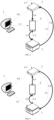
- FIG. 1 is a schematic diagram illustrating a system for testing call quality according to an example of the present disclosure.
- the testing system may include: a control device 1, a testing device 2, a simulation base station 3, a tested communication device 4 and the like.
- the control device 1 controls the simulation base station 3 and/or the tested communication device 4.
- An efficient call quality test can be achieved by performing data interaction and processing among the testing device 2, the simulation base station 3 and the tested communication device 4.
- the control device 1 may be an electronic device with a control function, such as a PC device, a server or the like.
- the testing device 2 may be a Mean Opinion Score (MOS) device which can express the call quality by calculating an MOS value. Alternatively, the call quality test may be implemented by using another parameter or device.
- the simulation base station 3 may be a Comprehensive Measurement Unit (CMU) or the like.
- the tested communication device 4 may be an electronic device with a call function, such as a mobile phone, a tablet device, or the like, where the call quality of the electronic device with the call function may be tested according to the technical solutions in the present disclosure.
- FIG. 2 is a flowchart illustrating a method of testing call quality according to an example of the present disclosure. As shown in FIG. 2 , the method may apply to the control device 1, which includes procedures as follows.
- control device 1 may transmit a call instruction to any party (hereinafter referred to as a first device) of the tested communication device 4 and the simulation base station 3 in a way that the first device originates the call to the other party (hereinafter referred to as a second device) of the tested communication device 4 and the simulation base station 3, where the second device is pre-configured to be under an automatic answering mode.
- the call is established between the tested communication device 4 and the simulation base station 2.
- the standard audio is processed to be a test audio by the tested communication device 4 during a transmission process via the call from the third device to the other party of the tested communication device 4 and the simulation base station 3 (hereinafter referred to as a fourth device), and the test audio is returned to the testing device 2 by the fourth device, so that the testing device 2 performs similarity comparison for the test audio and the standard audio.
- FIG. 3 is a schematic diagram illustrating a process of testing call quality according to an example of the present disclosure. As shown in FIG. 3 , the process of testing call quality includes procedures as follows.
- a connection may be established between the control device 1 and the tested communication device 4 through a physical line or through a wireless way, and the above-mentioned call instruction is transmitted via the connection.
- the physical line may be a USB cable or the like.
- the wireless connection may be established based on Bluetooth, WIFI, or the like.
- the simulation base station 3 may transmit a notification message to the testing device 2 after the call connection is established with the tested communication device 4.
- a wired or wireless connection may further be established between the simulation base station 3 and the testing device 2, which is not repeatedly described herein.
- a headphone with a microphone may be inserted into a headphone jack of the tested communication device 4, and the microphone on the headphone performs audio acquisition for the standard audio played by the testing device 2 in a way that the standard audio is inputted to the tested communication device 4.
- the tested communication device 4 processes the standard audio to be the test audio.
- the simulation base station 3 transmits the test audio to the testing device 2.
- the process that the simulation base station 3 receives and transmits the test audio are completely based on a digital signal transmitting process during which no analog-to-digital conversion operation is performed, thus, the data of the test audio is not changed, and data integrity and test accuracy for the test audio is not affected.
- the testing device 2 compares the test audio with the standard audio to obtain a test result.
- the testing device 2 outputs the test result to the control device 1.
- the testing device 2 may calculate an MOS corresponding to the test audio based on the standard audio, and determine the call quality of the tested communication device 4 based on the MOS. For example, when the calculated MOS is high, it is indicated that a similarity between the test audio and the standard audio is high, and the call quality of the tested communication device 4 is high. On the contrary, when the calculated MOS is low, it is indicated that the similarity between the test audio and the standard audio is low, and the call quality is low.
- the simulation base station 3 in response to the call instruction, establishes a call connection with the tested communication device 4.
- the simulation base station 3 may originate a call operation to the tested communication device 4, and the tested communication device 4 may be pre-configured to be under an automatic answering mode in a way that the tested communication device 4 can automatically answer the call in response to the call operation of the simulation base station 3 to establish the call between the tested communication device 4 and the simulation base station 3.
- the simulation base station 3 forwards the standard audio to the tested communication device 4.
- the testing device 2 Under the control of the control device 1, the testing device 2, the simulation base station 3 and the tested communication device 4 can automatically cooperate with one another, thereby achieving a fast, efficient and automatic call quality test for the tested communication device 4. Further, a simulation network may be created through the simulation base station 3 to implement the call connection with the tested communication device 4, thus, the problems such as that a test is inaccurate due to instability of an external communication network can be avoided, call quality testing accuracy can be significantly improved.
- FIG. 5 is a schematic diagram illustrating a structure of an apparatus for testing call quality according to an example of the present disclosure.
- the apparatus includes an establishing module 51 and a receiving module 52.
- the receiving module 52 may be configured to receive the similarity comparison result returned by the testing device to determine the call quality of the tested communication device.
- the first calling sub-module 511 may be configured to control the tested communication device to originate a call to the simulation base station, wherein the simulation base station may be configured to be under an automatic answering mode.
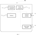
- the apparatus 700 may further include a power component 726 configured to execute power management for the device 700, a wired or wireless network interface 750 configured to connect the device 700 to a network, and an Input/Output (I/O) interface 758.
- the device 700 may be operated based on an operating system stored in the memory 732, such as Windows ServerTM, Mac OS XTM, UnixTM, LinuxTM, FreeBSDTM or the like.
Landscapes
- Engineering & Computer Science (AREA)
- Signal Processing (AREA)
- Audiology, Speech & Language Pathology (AREA)
- Health & Medical Sciences (AREA)
- Computer Networks & Wireless Communication (AREA)
- Physics & Mathematics (AREA)
- Quality & Reliability (AREA)
- Human Computer Interaction (AREA)
- Computational Linguistics (AREA)
- Acoustics & Sound (AREA)
- Multimedia (AREA)
- Mobile Radio Communication Systems (AREA)
- Telephone Function (AREA)
- Electromagnetism (AREA)
Description
- The present disclosure relates to terminal technical fields, and more particularly, to a system, a method and a device for testing call quality.
- As the development of communication technologies, the call quality desired by users becomes higher and higher. Thus, it is needed to develop test communication devices for discovering possible problems associated with the call quality.
-
US2016261737 A1 discloses a communication system comprising a communication terminal apparatus and a voice communication quality evaluation system capable of communicating with the communication terminal apparatus via communication networks. -
US2012128134 A1 relates to systems, methods, and computer program products for testing a voice communication system. -
US 2008/292113 A1 discloses methods and apparatus for tuning the audio path response of an audio device. -
US 2013/286860 A1 discloses an automated method for testing audio signal quality of cell phone transmissions providing a Mean Opinion Score (MOS) output using inexpensive test components. - The present disclosure provides a system, a method and a device for testing call quality.
- The present invention is defined by the appended claims. Further aspects of the present invention are defined in the dependent claims.
- It should be understood that general descriptions above and detailed descriptions below are merely illustrative and explanatory without limiting the present disclosure.
- The accompanying drawings herein, which are incorporated in and constitute a part of this specification, illustrate examples consistent with the present disclosure and serve to explain the principles of the present disclosure together with the specification.
-
FIG. 1 is a schematic diagram illustrating a structure of a system for testing call quality according to an example of the present disclosure. -
FIG. 2 is a flowchart illustrating a method of testing call quality according to an example of the present disclosure. -
FIG. 3 is a schematic diagram illustrating a process of testing call quality according to an example of the present disclosure. -
FIG. 4 is a schematic diagram illustrating another process of testing call quality according to an example of the present disclosure. -
FIGS. 5-6 are schematic diagrams illustrating structures of apparatuses for testing call quality according to examples of the present disclosure. -
FIG. 7 is a schematic diagram illustrating a structure of a device for testing call quality according to an example of the present disclosure. - Skilled artisans will appreciate that elements in the figures are illustrated for simplicity and clarity and have not necessarily been drawn to scale. For example, the dimensions and/or relative positioning of some of the elements in the figures may be exaggerated relative to other elements to help to improve understanding of various examples of the present disclosure. Also, common but well-understood elements that are useful or necessary in a commercially feasible example are often not depicted in order to facilitate a less obstructed view of these various examples. It will further be appreciated that certain actions and/or steps may be described or depicted in a particular order of occurrence while those skilled in the art will understand that such specificity with respect to sequence is not actually required. It will also be understood that the terms and expressions used herein have the ordinary technical meaning as is accorded to such terms and expressions by persons skilled in the technical field as set forth above, except where different specific meanings have otherwise been set forth herein.
- Example embodiments will be described in detail herein with the examples thereof expressed in the drawings. When the following descriptions involve the drawings, like numerals in different drawings represent like or similar elements unless stated otherwise. The implementations described in the following example embodiments do not represent all implementations consistent with the present disclosure. On the contrary, they are examples of a device and a method consistent with some aspects of the present disclosure described in detail in the appended claims.
- The terminology used in the present disclosure is for the purpose of describing exemplary examples only and is not intended to limit the present disclosure. As used in the present disclosure and the appended claims, the singular forms "a," "an" and "the" are intended to include the plural forms as well, unless the context clearly indicates otherwise. It shall also be understood that the terms "or" and "and/or" used herein are intended to signify and include any or all possible combinations of one or more of the associated listed items, unless the context clearly indicates otherwise.
- It shall be understood that, although the terms "first," "second," "third," and the like may be used herein to describe various information, the information should not be limited by these terms. These terms are only used to distinguish one category of information from another. For example, without departing from the scope of the present disclosure, first information may be termed as second information; and similarly, second information may also be termed as first information. As used herein, the term "if" may be understood to mean "when" or "upon" or "in response to" depending on the context.
- References throughout this specification to "one embodiment," "an embodiment," "exemplary embodiment," or the like in the singular or plural means that one or more particular features, structures, or characteristics described in connection with an example is included in at least one embodiment of the present disclosure. Thus, the appearances of the phrases "in one embodiment," "in an embodiment," "in an exemplary embodiment," or the like in the singular or plural in various places throughout this specification are not necessarily all referring to the same embodiment. Furthermore, the particular features, structures, or characteristics in one or more embodiments may be combined in any suitable manner.
-
FIG. 1 is a schematic diagram illustrating a system for testing call quality according to an example of the present disclosure. As shown inFIG. 1 , the testing system may include: acontrol device 1, atesting device 2, asimulation base station 3, a testedcommunication device 4 and the like. According to examples of the present disclosure, thecontrol device 1 controls thesimulation base station 3 and/or the testedcommunication device 4. An efficient call quality test can be achieved by performing data interaction and processing among thetesting device 2, thesimulation base station 3 and the testedcommunication device 4. - The
control device 1 may be an electronic device with a control function, such as a PC device, a server or the like. Thetesting device 2 may be a Mean Opinion Score (MOS) device which can express the call quality by calculating an MOS value. Alternatively, the call quality test may be implemented by using another parameter or device. Thesimulation base station 3 may be a Comprehensive Measurement Unit (CMU) or the like. The testedcommunication device 4 may be an electronic device with a call function, such as a mobile phone, a tablet device, or the like, where the call quality of the electronic device with the call function may be tested according to the technical solutions in the present disclosure. -
FIG. 2 is a flowchart illustrating a method of testing call quality according to an example of the present disclosure. As shown inFIG. 2 , the method may apply to thecontrol device 1, which includes procedures as follows. - At
block 202, it is controlled to establish a call between the testedcommunication device 4 and thesimulation base station 3. - In the example, the
control device 1 may transmit a call instruction to any party (hereinafter referred to as a first device) of the testedcommunication device 4 and thesimulation base station 3 in a way that the first device originates the call to the other party (hereinafter referred to as a second device) of the testedcommunication device 4 and thesimulation base station 3, where the second device is pre-configured to be under an automatic answering mode. Thus, the call is established between the testedcommunication device 4 and thesimulation base station 2. - In the example, the
testing device 2 may provide a standard audio to any party (hereinafter referred to as a third device) of the testedcommunication device 4 and thesimulation base station 3 after the call is established. For example, thesimulation base station 3 may transmit a notification message to thetesting device 2 after the call is established, so that thetesting device 2 provides the standard audio to the third device. - The standard audio is processed to be a test audio by the tested
communication device 4 during a transmission process via the call from the third device to the other party of the testedcommunication device 4 and the simulation base station 3 (hereinafter referred to as a fourth device), and the test audio is returned to thetesting device 2 by the fourth device, so that thetesting device 2 performs similarity comparison for the test audio and the standard audio. - It should to be noted that, the process that the
control device 1 transmits the call instruction to the first device and the process that thetesting device 2 provides the standard audio to the third device are independent from each other, the first device may be same as or different from the third device. - When the third device is the tested
communication device 4, thetesting device 2 may play the standard audio for the testedcommunication device 4. In this case, the testedcommunication device 4 may obtain the test audio by performing acquisition for the played standard audio through a built-in microphone or an external microphone. When the third device is thesimulation base station 3, thetesting device 2 transmits the standard audio to thesimulation base station 3. In this case, thesimulation base station 3 transmits the standard audio as a call voice to the testedcommunication device 4, and the testedcommunication device 4 obtains the test audio by performing acquisition for the standard audio. - It should be understood that the standard audio is the audio data which is not processed by the tested
communication device 4, and the test audio is the audio data which has been processed by the testedcommunication device 4. Further, a communication network can be established between the testedcommunication device 4 and thesimulation base station 3 by configuring thesimulation base station 3, so as to avoid that the quality of the test audio is influenced by network environment factors in a communication process. In other words, it can be ensured that a quality condition of the test audio is only related to the call quality of the testedcommunication device 4, thereby improving call quality test accuracy. - At
block 204, the similarity comparison result returned from thetesting device 2 is received, so as to determine the call quality of the testedcommunication device 4. - In the example, the call quality is positively correlated to a similarity between the test audio and the standard audio. For example, when the call quality of the tested
communication device 4 is higher, the standard audio is changed less by the testedcommunication device 4 in a way that the similarity between the test audio and the corresponding standard audio is higher. On the contrary, when the similarity between the test audio and the standard audio is lower, it is indicated that the call quality of the testedcommunication device 4 is lower. - As can be seen from examples above, the call operation is performed by using the simulation base station according to the present disclosure in a way that a stable network environment can be continuously provided, an influence of a network instability factor for a test result can be eliminated, and an efficient call quality test can be implemented. Further, the control device controls the testing device, the simulation base station and the tested communication device in a way that the three can automatically cooperate with each another. Thus, the call quality of the tested communication device can be automatically tested, and call quality testing efficiency for the tested communication device can be further effectively improved.
-
FIG. 3 is a schematic diagram illustrating a process of testing call quality according to an example of the present disclosure. As shown inFIG. 3 , the process of testing call quality includes procedures as follows. - At process 3.1, the
control device 1 transmits a call instruction to the testedcommunication device 4. - In the example, a connection may be established between the
control device 1 and the testedcommunication device 4 through a physical line or through a wireless way, and the above-mentioned call instruction is transmitted via the connection. For example, the physical line may be a USB cable or the like. The wireless connection may be established based on Bluetooth, WIFI, or the like. - At process 3.2, in response to the call instruction, the tested
communication device 4 establishes a call with thesimulation base station 3. - In the example, the tested
communication device 4 may originate a call to thesimulation base station 3, and thesimulation base station 3 may be pre-configured to be under an automatic answering mode, so that thesimulation base station 3 may automatically answer the call in response to the call from the testedcommunication device 4 to establish the call connection between the testedcommunication device 4 and thesimulation base station 3. - At process 3.3, the
simulation base station 3 may transmit a notification message to thetesting device 2 after the call connection is established with the testedcommunication device 4. - In the example, similar as the connection established between the
control device 1 and the testedcommunication device 4, a wired or wireless connection may further be established between thesimulation base station 3 and thetesting device 2, which is not repeatedly described herein. - At process 3.4, the
testing device 2 transmits a standard audio to the testedcommunication device 4. - In an example, the
testing device 2 plays the standard audio through a loudspeaker or the like, and the testedcommunication device 4 generates the corresponding test audio by performing audio acquisition for the standard audio through a microphone. The process may be employed to simulate a scenario that a user directly performs a voice call based on the microphone on the testedcommunication device 4. - In another example, a headphone with a microphone may be inserted into a headphone jack of the tested
communication device 4, and the microphone on the headphone performs audio acquisition for the standard audio played by thetesting device 2 in a way that the standard audio is inputted to the testedcommunication device 4. The testedcommunication device 4 processes the standard audio to be the test audio. - In the example, the process that the tested
communication device 4 generates the test audio based on the standard audio is actually a process that a digital audio signal is generated based on an analog audio signal through an analog-to-digital conversion. In the analog-to-digital conversion process, any improper operation likely causes that original data is lost and noise is added in a way that the actual call quality is influenced. In examples of the present disclosure, any possible call quality problem of the testedcommunication device 4 is expected to be detected by simulating the actual call process, thereby the call quality problem can be discovered and solved quickly. - At process 3.5, the tested
communication device 4 transmits the test audio to thesimulation base station 3. - In the example, after the tested
communication device 4 establishes the call connection with thesimulation base station 3, it is equivalent to establishing a data connection between testedcommunication device 4 and thesimulation base station 3, and the transmission operation for data such as the test audio may be implemented via the data connection. The data connection may be based on a circuit switched domain or a packet switched domain or other data connection means, which is not limited herein. - At process 3.6, the
simulation base station 3 transmits the test audio to thetesting device 2. - In the example, the process that the
simulation base station 3 receives and transmits the test audio are completely based on a digital signal transmitting process during which no analog-to-digital conversion operation is performed, thus, the data of the test audio is not changed, and data integrity and test accuracy for the test audio is not affected. - At process 3.7, the
testing device 2 compares the test audio with the standard audio to obtain a test result. - At process 3.8, the
testing device 2 outputs the test result to thecontrol device 1. - In the example, when the
testing device 2 is an MOS device, thetesting device 2 may calculate an MOS corresponding to the test audio based on the standard audio, and determine the call quality of the testedcommunication device 4 based on the MOS. For example, when the calculated MOS is high, it is indicated that a similarity between the test audio and the standard audio is high, and the call quality of the testedcommunication device 4 is high. On the contrary, when the calculated MOS is low, it is indicated that the similarity between the test audio and the standard audio is low, and the call quality is low. - In the example, after the
testing device 2 outputs the test result to thecontrol device 1, thecontrol device 1 may display the test result on a display screen. Alternatively, thecontrol device 1 may output the corresponding test result via the display screen for a user to view only when the test result indicates that the call quality is lower than a preset quality standard or another pre-determined threshold. - Sometimes, the testing device may generate a standard audio that also includes data message in addition to the audio. For example, the standard audio may include a short message. Thus, the tested communication device may receive the standard audio that includes data message and the audio and generate the test data that also include data message and audio. The comparison between the standard audio and the test audio may also include the comparisons of the data message included in the standard audio and the test audio.
- Sometimes, the standard audio may include the data message only. In this case, the test audio generated by the tested communication device may also include the data message only. The comparison between the standard audio and the test audio may compare the data message included in the standard audio and the test audio.
-
FIG. 4 is a schematic diagram illustrating another process of testing call quality according to an example of the present disclosure. As shown inFIG. 4 , the process of testing call quality include procedures as follows: - At process 4.1, the
control device 1 transmits a call instruction to thesimulation base station 3. - In the example, a connection may be established between the
control device 1 and thesimulation base station 3 through a physical line or through a wireless way, and the above-mentioned call instruction is transmitted via the connection. For example, the physical line may be a USB cable or the like. The wireless connection may be established based on Bluetooth, WIFI or the like. - At process 4.2, in response to the call instruction, the
simulation base station 3 establishes a call connection with the testedcommunication device 4. - In the example, the
simulation base station 3 may originate a call operation to the testedcommunication device 4, and the testedcommunication device 4 may be pre-configured to be under an automatic answering mode in a way that the testedcommunication device 4 can automatically answer the call in response to the call operation of thesimulation base station 3 to establish the call between the testedcommunication device 4 and thesimulation base station 3. - It should to be noted that, in the example shown in
FIG. 4 , a call may be established between thesimulation base station 3 and the testedcommunication device 4 by executing procedures in processes 3.1 and 3.2 shown inFIG. 3 to replace processes 4.1 and 4.2 herein; similarly, processes 4.1 and 4.2 herein may further be used in the example shown inFIG. 3 to replace processes 3.1 and 3.2 to establish the call between thesimulation base station 3 and the testedcommunication device 4. - At process 4.3, the
simulation base station 3 transmits a notification message to thetesting device 2 after the call is established. - In the example, similar as the connection established between the
control device 1 and the testedcommunication device 4, the wired or wireless connection may further be established between thesimulation base station 3 and thetesting device 2, which is not repeatedly described herein. - At process 4.4, the
testing device 2 transmits the standard audio to thesimulation base station 3. - At process 4.5, the
simulation base station 3 forwards the standard audio to the testedcommunication device 4. - In the example, the process that the
simulation base station 3 receives and transmits the standard audio are completely based on a digital signal transmitting process during which no analog-to-digital conversion operation is performed, thus, the data of the standard audio is not changed, and data integrity and test accuracy for the standard audio is not affected. - The tested
communication device 4 processes the standard audio to be the test audio and transmits the test audio to thetesting device 2 in a way that thetesting device 2 obtains the test audio. - In the example, the tested
communication device 4 may process the standard audio to be an analog signal through digital-to-analog conversion and play the analog signal through a loudspeaker or a headphone receiver connected with the testedcommunication device 4, and thetesting device 2 obtains the test audio by performing audio acquisition. - In the example, the process that the tested
communication device 4 performs digital-to-analog conversion is actually a process that the digital audio signal is converted to an analog audio signal. Any improper operation likely causes that original data is lost and noise is added in a way that the actual call quality is influenced. In examples of the present disclosure, any possible call quality problem of the testedcommunication device 4 is expected to be detected by simulating the actual call process, thereby the call quality problem can be discovered and solved soon. - The
testing device 2 compares the test audio with the standard audio to obtain a corresponding test result. - The
testing device 2 outputs the test result to thecontrol device 1. - In the example, procedures in processes 4.7 and 4.8 are similar as those in processes 3.7 and 3.8 as shown in
FIG. 3 , which is not repeatedly described herein. - Under the control of the
control device 1, thetesting device 2, thesimulation base station 3 and the testedcommunication device 4 can automatically cooperate with one another, thereby achieving a fast, efficient and automatic call quality test for the testedcommunication device 4. Further, a simulation network may be created through thesimulation base station 3 to implement the call connection with the testedcommunication device 4, thus, the problems such as that a test is inaccurate due to instability of an external communication network can be avoided, call quality testing accuracy can be significantly improved. - Corresponding to the aforementioned methods of testing call quality according to examples of the present disclosure, devices for testing call quality according to the present disclosure are described below.
-
FIG. 5 is a schematic diagram illustrating a structure of an apparatus for testing call quality according to an example of the present disclosure. Referring toFIG. 5 , the apparatus includes an establishingmodule 51 and a receivingmodule 52. - The establishing
unit 51 may be configured to control the establishment of a call between a tested communication device and a simulation base station, where a testing device provides a standard audio to any party of the tested communication device and the simulation base station after the call is established; the standard audio is processed by the tested communication device to be a test audio during a transmission process via the call, and the test audio is returned to the testing device in a way that the testing device performs similarity comparison for the test audio and the standard audio to obtain a similarity comparison result which expresses the call quality of the tested communication device. - The receiving
module 52 may be configured to receive the similarity comparison result returned by the testing device to determine the call quality of the tested communication device. -
FIG. 6 is a schematic diagram illustrating a structure of another apparatus for testing call quality according to an example of the present disclosure. Based on the structure shown inFIG. 5 , the establishingmodule 51 may include a first calling sub-module 511 or asecond calling sub-module 512. - The first calling sub-module 511 may be configured to control the tested communication device to originate a call to the simulation base station, wherein the simulation base station may be configured to be under an automatic answering mode.
- The
second calling sub-module 511 may be configured to control the simulation base station to originate a call to the tested communication device, where the tested communication device may be configured to be under an automatic answering mode. - In an example, the call quality is positively correlated to a similarity between the test audio and the standard audio.
- Regarding the apparatuses in the examples above, specific manners in which different modules perform operations have already been described in detail in the examples related to the methods, which is not repeatedly described in detail herein.
- Since apparatus examples substantially correspond to method examples, related parts for the apparatuses can refer to descriptions for the method example. The apparatus examples described above are merely illustrative, where the modules described as separate members may be or not be physically separated, and the members displayed as units may be or not be physical units, i.e., may be located in one place, or may be distributed to a plurality of network units. Part or all of the modules may be selected according to actual requirements to implement the objectives of the solutions in the embodiments. Those of ordinary skill in the art may understand and carry out them without creative work.
- Correspondingly, the present disclosure further provides a device for testing call quality. The device includes: a processor, and a non-transitory machine-readable storage medium storing machine executable instructions which are executable by the processor to: control establishment of a call between a tested communication device and a simulation base station where a testing device provides a standard audio to any party of the tested communication device and the simulation base station after the call is established, and the standard audio is processed by the tested communication device to be a test audio during a transmission process via the call, and the test audio is returned to the testing device in a way that the testing device performs similarity comparison for the test audio and the standard audio to obtain a similarity comparison result which expresses the call quality of the tested communication device; and receive the similarity comparison result returned by the testing device to determine the call quality of the tested communication device.
- Correspondingly, the present disclosure further provides an electronic device. The electronic device includes a machine-readable storage medium and one or more programs, where the one or more programs are stored in the machine-readable storage medium. The one or more programs includes instructions which can be invoked and executed by the one or more processors to: control establishment of a call between a tested communication device and a simulation base station where a testing device provides a standard audio to any party of the tested communication device and the simulation base station after the call is established, and the standard audio is processed by the tested communication device to be a test audio during a transmission process via the call, and the test audio is returned to the testing device in a way that the testing device performs similarity comparison for the test audio and the standard audio to obtain a similarity comparison result which expresses the call quality of the tested communication device; and receive the similarity comparison result returned by the testing device to determine the call quality of the tested communication device.
-
FIG. 7 is a schematic diagram illustrating adevice 700 for testing call quality according to an example of the present disclosure. For example, thedevice 700 may be provided as a server. Referring toFIG. 7 , thedevice 700 includes aprocessing component 722 which includes one or more processors, and a memory resource represented by amemory 732 storing instructions which can be invoked and executed by theprocessing component 722, e.g., application programs. The application programs stored in thememory 732 may include one or more modules respectively corresponding to a group of instructions. - The
apparatus 700 may further include apower component 726 configured to execute power management for thedevice 700, a wired orwireless network interface 750 configured to connect thedevice 700 to a network, and an Input/Output (I/O)interface 758. Thedevice 700 may be operated based on an operating system stored in thememory 732, such as Windows ServerTM, Mac OS XTM, UnixTM, LinuxTM, FreeBSDTM or the like. - The present disclosure may include dedicated hardware implementations such as application specific integrated circuits, programmable logic arrays and other hardware devices. The hardware implementations can be constructed to implement one or more of the methods described herein. Applications that may include the apparatus and systems of various examples can broadly include a variety of electronic and computing systems. One or more examples described herein may implement functions using two or more specific interconnected hardware modules or devices with related control and data signals that can be communicated between and through the modules, or as portions of an application-specific integrated circuit. Accordingly, the computing system disclosed may encompass software, firmware, and hardware implementations. The terms "module," "sub-module," "circuit," "sub-circuit," "circuitry," "sub-circuitry," "unit," or "sub-unit" may include memory (shared, dedicated, or group) that stores code or instructions that can be executed by one or more processors.
- It would be easy for a person skilled in the art to conceive of other embodiments of the present disclosure after considering the description and practicing the disclosure herein. The present disclosure is intended to encompass any variations and use or adaptive changes of the present disclosure. These variations, uses or adaptive changes follow the general principles of the present disclosure and include the common general knowledge or customary technical means in the technical field that are not disclosed herein. The specification and the embodiments are merely illustrative, and the real scope of the present disclosure are defined by the appended claims.
- It shall be understood that the present disclosure is not limited to the exact structures as described above and depicted in the drawings, and various modifications and alterations may be made thereto without departing from the scope of the present disclosure. The scope of the present disclosure is just limited by the appended claims.
Claims (9)
- A system for testing call quality, comprising:a simulation base station (3);a tested communication device (4);a control device (1), configured to transmit a call instruction to the tested communication device (4) such that a call between the tested communication device (4) and the simulation base station (3) is established;a testing device (2), configured to:provide a standard analog audio to the tested communication device (4) after the call is established between the tested communication device (4) and the simulation base station (3), wherein the standard analog audio becomes a test audio after it is processed by the tested communication device (4) and the test audio is transmitted to the simulation base station (3) during a transmission process via the call, and the test audio is sent back to the testing device (2) by the simulation base station (3), and the test audio is not changed during the transmission process; andperform a similarity comparison between the test audio and the standard analog audio to obtain a similarity comparison result, wherein the similarity comparison result shows the call quality of the tested communication device (4),wherein the tested communication device (4) is configured to originate the call to the simulation base station (3) in response to the call instruction, and the simulation base station (3) is configured to enter an automatic answering mode.
- The system of claim 1, wherein:the simulation base station (3) is configured to transmit a notification message to the testing device (2) after the call is established; andthe testing device (2) is configured to provide the standard audio to the tested communication device (4) in response to the notification message.
- The system of claim 1, wherein
the tested communication device (4) is configured to obtain the test audio by using a built-in microphone or an external microphone when the testing device (2) plays the standard audio. - The system of claim 1, wherein
the tested communication device (4) is configured to process the received standard audio and turn the standard audio to be the test audio. - The system of claim 1, wherein the similarity comparison result is a Mean Opinion Score, MOS, when the testing device is a MOS testing device.
- A method of testing call quality, comprising:establishing a call between a tested communication device (4) and a simulation base station (3);providing, by a testing device (2), a standard analog audio to the tested communication device (4) after the call is established between the tested communication device (4) and the simulation base station (3);processing the standard analog audio and turning the standard analog audio to be a test audio and transmitting the test audio to the simulation base station (3) by using the tested communication device (4) during a transmission process via the call, and sending the test audio back to the testing device (2) by the simulation base station (3), wherein the test audio is not changed during the transmission process;performing, by the testing device (2), a similarity comparison between the test audio and the standard audio to obtain a similarity comparison result wherein the similarity comparison result shows the call quality of the tested communication device (4); andreceiving the similarity comparison result from the testing device (2) to determine the call quality of the tested communication device (4),wherein establishing the call between the tested communication device (4) and the simulation base station (3) further comprises:
controlling the tested communication device (4) to originate the call to the simulation base station (3), wherein the simulation base station (3) is configured to enter an automatic answering mode. - The method of claim 6, wherein the call quality is correlated to a similarity between the test audio and the standard audio.
- A control device (1) capable of controlling a test system comprising a simulation base station (3), a tested communication device (4), a testing device (2) and the control device (1), comprizing:a processor (722), anda non-transitory machine-readable storage medium (732) storing machine executable instructions, wherein the machine executable instructions are executable by the processor and cause the processor to:
control (202) to establish a call between the tested communication device (4) and the simulation base station (3), wherein the call is capable of being used to transmit test audio to the simulation base station (3) by the tested communication device (4), wherein the test audio is obtained by processing the standard analog audio provided by the testing device (2) with tested communication device (4); andreceive (204) the similarity comparison result returned by the testing device (2) to determine the call quality of the tested communication device (4), wherein,the machine-executable instructions further cause the processor to:
control the tested communication device (4) to originate the call to the simulation base station (3), wherein the simulation base station (3) is configured to enter an automatic answering mode. - The control device of claim 8, wherein the call quality is correlated to a similarity between the test audio and the standard audio.
Applications Claiming Priority (1)
| Application Number | Priority Date | Filing Date | Title |
|---|---|---|---|
| CN201610903634.7A CN106504770B (en) | 2016-10-17 | 2016-10-17 | Call quality testing system, testing method and testing device |
Publications (2)
| Publication Number | Publication Date |
|---|---|
| EP3310028A1 EP3310028A1 (en) | 2018-04-18 |
| EP3310028B1 true EP3310028B1 (en) | 2024-07-03 |
Family
ID=58295384
Family Applications (1)
| Application Number | Title | Priority Date | Filing Date |
|---|---|---|---|
| EP17196642.7A Active EP3310028B1 (en) | 2016-10-17 | 2017-10-16 | System, method and device for testing call quality |
Country Status (3)
| Country | Link |
|---|---|
| US (1) | US20180109337A1 (en) |
| EP (1) | EP3310028B1 (en) |
| CN (1) | CN106504770B (en) |
Families Citing this family (13)
| Publication number | Priority date | Publication date | Assignee | Title |
|---|---|---|---|---|
| CN108391280A (en) * | 2018-01-08 | 2018-08-10 | 东莞市慧眼数字技术有限公司 | Signal test system and method based on NB-IOT network |
| CN110505352B (en) * | 2018-05-17 | 2021-09-24 | 腾讯科技(深圳)有限公司 | Call quality testing method, system, computer equipment and computer storage medium |
| CN108966263A (en) * | 2018-07-26 | 2018-12-07 | 广东经纬天地科技股份有限公司 | A kind of blue tooth voice MOS portable instrumentation system |
| US10516777B1 (en) * | 2018-09-11 | 2019-12-24 | Qualcomm Incorporated | Enhanced user experience for voice communication |
| CN111629396A (en) * | 2019-02-27 | 2020-09-04 | 北京小米移动软件有限公司 | Test system and test method for call quality |
| CN110070892A (en) * | 2019-04-09 | 2019-07-30 | 易联科技(深圳)有限公司 | A kind of test macro of talk back equipment speech quality |
| CN111405122B (en) * | 2020-03-18 | 2021-09-24 | 苏州科达科技股份有限公司 | Audio call testing method, device and storage medium |
| CN111863032A (en) * | 2020-06-12 | 2020-10-30 | 随锐科技集团股份有限公司 | Preferred method and system for audio collection device, computer readable storage medium |
| CN111901746A (en) * | 2020-07-15 | 2020-11-06 | 交通运输部规划研究院 | Method and system for testing very high frequency communication coverage effect of mobile station |
| CN114050962B (en) * | 2020-07-24 | 2023-01-13 | 荣耀终端有限公司 | Communication fault detection method and device and computer readable storage medium |
| CN111741168B (en) * | 2020-08-07 | 2022-02-18 | 睿云联(厦门)网络通讯技术有限公司 | A communication equipment testing method, apparatus, computer readable medium and equipment thereof |
| CN112489684A (en) * | 2020-12-02 | 2021-03-12 | 公安部第三研究所 | End-to-end audio signal communication conversion detection method |
| CN115762575B (en) * | 2021-09-02 | 2026-03-17 | 大唐联仪科技有限公司 | Terminal Voice Quality Evaluation System and Method |
Citations (2)
| Publication number | Priority date | Publication date | Assignee | Title |
|---|---|---|---|---|
| US20080292113A1 (en) * | 2007-04-13 | 2008-11-27 | Qualcomm Incorporated | Method and apparatus for audio path filter tuning |
| US20130286860A1 (en) * | 2012-04-25 | 2013-10-31 | Anritsu Company | Impairment simulation for network communication to enable voice quality degradation estimation |
Family Cites Families (11)
| Publication number | Priority date | Publication date | Assignee | Title |
|---|---|---|---|---|
| US6567381B1 (en) * | 1999-12-21 | 2003-05-20 | Willtech Incorporation | Method and apparatus for automatic call test in a CDMA system |
| US6751457B1 (en) * | 2000-06-28 | 2004-06-15 | Bellsouth Intellectual Property Corporation | Real time call monitoring system and method |
| JP3916591B2 (en) * | 2003-06-16 | 2007-05-16 | アンリツ株式会社 | Test equipment |
| US8737571B1 (en) * | 2004-06-29 | 2014-05-27 | Empirix Inc. | Methods and apparatus providing call quality testing |
| CN101030824A (en) * | 2006-03-02 | 2007-09-05 | 昆达电脑科技(昆山)有限公司 | System and method for testing cell-phone radio-frequency signal |
| US8594278B2 (en) * | 2010-11-23 | 2013-11-26 | Ipc Systems, Inc. | Test system for voice communications systems |
| CN102355688A (en) * | 2011-09-05 | 2012-02-15 | 大唐移动通信设备有限公司 | Equipment testing system and method |
| CN103249069B (en) * | 2012-02-14 | 2016-04-06 | 展讯通信(上海)有限公司 | The test macro of the method for testing of mobile terminal and testing equipment, mobile terminal |
| US9277331B2 (en) * | 2014-02-24 | 2016-03-01 | PCTEST Engineering Laboratory, Inc. | Techniques for testing compatibility of a wireless communication device |
| JP6087950B2 (en) * | 2014-04-02 | 2017-03-01 | ソフトバンク株式会社 | Communication system and communication method |
| US9838544B2 (en) * | 2014-06-27 | 2017-12-05 | Agora Lab, Inc. | Systems and methods for improved quality of a call over network with load leveling and last mile signal indication |
-
2016
- 2016-10-17 CN CN201610903634.7A patent/CN106504770B/en active Active
-
2017
- 2017-10-16 EP EP17196642.7A patent/EP3310028B1/en active Active
- 2017-10-17 US US15/785,873 patent/US20180109337A1/en not_active Abandoned
Patent Citations (2)
| Publication number | Priority date | Publication date | Assignee | Title |
|---|---|---|---|---|
| US20080292113A1 (en) * | 2007-04-13 | 2008-11-27 | Qualcomm Incorporated | Method and apparatus for audio path filter tuning |
| US20130286860A1 (en) * | 2012-04-25 | 2013-10-31 | Anritsu Company | Impairment simulation for network communication to enable voice quality degradation estimation |
Also Published As
| Publication number | Publication date |
|---|---|
| CN106504770A (en) | 2017-03-15 |
| EP3310028A1 (en) | 2018-04-18 |
| US20180109337A1 (en) | 2018-04-19 |
| CN106504770B (en) | 2020-03-17 |
Similar Documents
| Publication | Publication Date | Title |
|---|---|---|
| EP3310028A1 (en) | System, method and device for testing call quality | |
| US12407481B2 (en) | Method for reporting CSI report, terminal device, and network device | |
| WO2021155768A1 (en) | Beam indication method and apparatus, and device and medium | |
| US10897513B2 (en) | Method and apparatus for selecting information pushed-to terminal | |
| UA129111C2 (en) | Relay reselection method, device and medium | |
| US11507340B2 (en) | Audio output method, electronic device, and storage medium | |
| US9992614B2 (en) | Wireless device pairing management | |
| US9652197B2 (en) | Information processing method, electronic apparatus and system | |
| US20170192883A1 (en) | Testing method for sdk and an electronic device, a testing system thereof | |
| JP2017085476A (en) | Audio system control program and control terminal device | |
| WO2016188181A1 (en) | Test method, mobile terminal, server and computer storage medium | |
| CN110602683B (en) | Bluetooth control method, device, mobile terminal and storage medium | |
| JP2021114697A (en) | Mobile terminal test device and out-of-service-area test control method thereof | |
| CN116567691A (en) | Information transmission method, device, terminal and network side equipment | |
| US10574316B1 (en) | Antenna switching for device with multiple antennas | |
| JP2025540464A (en) | Resource restriction indication method, device, and storage medium | |
| EP2933990A1 (en) | Method and device for prompting a user | |
| CN111800861A (en) | Power control method and device | |
| CN105161119B (en) | Method and terminal for synchronously playing music by grouping sound boxes | |
| CN106371800A (en) | Audio output method and device | |
| CN111092669B (en) | User equipment testing system, method, device, signaling comprehensive tester and storage medium | |
| CN107483855B (en) | Television audio control method, television and computer-readable storage medium | |
| CN105070303A (en) | A speaker grouping method and terminal | |
| US20250274791A1 (en) | Measurement relaxation method, and terminal and network-side device | |
| CN111586732A (en) | Terminal test method, terminal test device, test equipment and storage medium |
Legal Events
| Date | Code | Title | Description |
|---|---|---|---|
| PUAI | Public reference made under article 153(3) epc to a published international application that has entered the european phase |
Free format text: ORIGINAL CODE: 0009012 |
|
| STAA | Information on the status of an ep patent application or granted ep patent |
Free format text: STATUS: REQUEST FOR EXAMINATION WAS MADE |
|
| 17P | Request for examination filed |
Effective date: 20171016 |
|
| AK | Designated contracting states |
Kind code of ref document: A1 Designated state(s): AL AT BE BG CH CY CZ DE DK EE ES FI FR GB GR HR HU IE IS IT LI LT LU LV MC MK MT NL NO PL PT RO RS SE SI SK SM TR |
|
| AX | Request for extension of the european patent |
Extension state: BA ME |
|
| RBV | Designated contracting states (corrected) |
Designated state(s): AL AT BE BG CH CY CZ DE DK EE ES FI FR GB GR HR HU IE IS IT LI LT LU LV MC MK MT NL NO PL PT RO RS SE SI SK SM TR |
|
| STAA | Information on the status of an ep patent application or granted ep patent |
Free format text: STATUS: EXAMINATION IS IN PROGRESS |
|
| 17Q | First examination report despatched |
Effective date: 20200915 |
|
| GRAP | Despatch of communication of intention to grant a patent |
Free format text: ORIGINAL CODE: EPIDOSNIGR1 |
|
| STAA | Information on the status of an ep patent application or granted ep patent |
Free format text: STATUS: GRANT OF PATENT IS INTENDED |
|
| INTG | Intention to grant announced |
Effective date: 20240312 |
|
| GRAS | Grant fee paid |
Free format text: ORIGINAL CODE: EPIDOSNIGR3 |
|
| P01 | Opt-out of the competence of the unified patent court (upc) registered |
Effective date: 20240423 |
|
| GRAA | (expected) grant |
Free format text: ORIGINAL CODE: 0009210 |
|
| STAA | Information on the status of an ep patent application or granted ep patent |
Free format text: STATUS: THE PATENT HAS BEEN GRANTED |
|
| AK | Designated contracting states |
Kind code of ref document: B1 Designated state(s): AL AT BE BG CH CY CZ DE DK EE ES FI FR GB GR HR HU IE IS IT LI LT LU LV MC MK MT NL NO PL PT RO RS SE SI SK SM TR |
|
| REG | Reference to a national code |
Ref country code: CH Ref legal event code: EP |
|
| REG | Reference to a national code |
Ref country code: DE Ref legal event code: R096 Ref document number: 602017082947 Country of ref document: DE |
|
| REG | Reference to a national code |
Ref country code: LT Ref legal event code: MG9D |
|
| REG | Reference to a national code |
Ref country code: NL Ref legal event code: MP Effective date: 20240703 |
|
| PG25 | Lapsed in a contracting state [announced via postgrant information from national office to epo] |
Ref country code: PT Free format text: LAPSE BECAUSE OF FAILURE TO SUBMIT A TRANSLATION OF THE DESCRIPTION OR TO PAY THE FEE WITHIN THE PRESCRIBED TIME-LIMIT Effective date: 20241104 |
|
| REG | Reference to a national code |
Ref country code: AT Ref legal event code: MK05 Ref document number: 1700974 Country of ref document: AT Kind code of ref document: T Effective date: 20240703 |
|
| PG25 | Lapsed in a contracting state [announced via postgrant information from national office to epo] |
Ref country code: NL Free format text: LAPSE BECAUSE OF FAILURE TO SUBMIT A TRANSLATION OF THE DESCRIPTION OR TO PAY THE FEE WITHIN THE PRESCRIBED TIME-LIMIT Effective date: 20240703 |
|
| PG25 | Lapsed in a contracting state [announced via postgrant information from national office to epo] |
Ref country code: PT Free format text: LAPSE BECAUSE OF FAILURE TO SUBMIT A TRANSLATION OF THE DESCRIPTION OR TO PAY THE FEE WITHIN THE PRESCRIBED TIME-LIMIT Effective date: 20241104 Ref country code: NL Free format text: LAPSE BECAUSE OF FAILURE TO SUBMIT A TRANSLATION OF THE DESCRIPTION OR TO PAY THE FEE WITHIN THE PRESCRIBED TIME-LIMIT Effective date: 20240703 |
|
| PG25 | Lapsed in a contracting state [announced via postgrant information from national office to epo] |
Ref country code: NO Free format text: LAPSE BECAUSE OF FAILURE TO SUBMIT A TRANSLATION OF THE DESCRIPTION OR TO PAY THE FEE WITHIN THE PRESCRIBED TIME-LIMIT Effective date: 20241003 |
|
| PG25 | Lapsed in a contracting state [announced via postgrant information from national office to epo] |
Ref country code: PL Free format text: LAPSE BECAUSE OF FAILURE TO SUBMIT A TRANSLATION OF THE DESCRIPTION OR TO PAY THE FEE WITHIN THE PRESCRIBED TIME-LIMIT Effective date: 20240703 Ref country code: FI Free format text: LAPSE BECAUSE OF FAILURE TO SUBMIT A TRANSLATION OF THE DESCRIPTION OR TO PAY THE FEE WITHIN THE PRESCRIBED TIME-LIMIT Effective date: 20240703 Ref country code: GR Free format text: LAPSE BECAUSE OF FAILURE TO SUBMIT A TRANSLATION OF THE DESCRIPTION OR TO PAY THE FEE WITHIN THE PRESCRIBED TIME-LIMIT Effective date: 20241004 |
|
| PG25 | Lapsed in a contracting state [announced via postgrant information from national office to epo] |
Ref country code: BG Free format text: LAPSE BECAUSE OF FAILURE TO SUBMIT A TRANSLATION OF THE DESCRIPTION OR TO PAY THE FEE WITHIN THE PRESCRIBED TIME-LIMIT Effective date: 20240703 |
|
| PG25 | Lapsed in a contracting state [announced via postgrant information from national office to epo] |
Ref country code: LV Free format text: LAPSE BECAUSE OF FAILURE TO SUBMIT A TRANSLATION OF THE DESCRIPTION OR TO PAY THE FEE WITHIN THE PRESCRIBED TIME-LIMIT Effective date: 20240703 |
|
| PG25 | Lapsed in a contracting state [announced via postgrant information from national office to epo] |
Ref country code: IS Free format text: LAPSE BECAUSE OF FAILURE TO SUBMIT A TRANSLATION OF THE DESCRIPTION OR TO PAY THE FEE WITHIN THE PRESCRIBED TIME-LIMIT Effective date: 20241103 Ref country code: AT Free format text: LAPSE BECAUSE OF FAILURE TO SUBMIT A TRANSLATION OF THE DESCRIPTION OR TO PAY THE FEE WITHIN THE PRESCRIBED TIME-LIMIT Effective date: 20240703 |
|
| PG25 | Lapsed in a contracting state [announced via postgrant information from national office to epo] |
Ref country code: CZ Free format text: LAPSE BECAUSE OF FAILURE TO SUBMIT A TRANSLATION OF THE DESCRIPTION OR TO PAY THE FEE WITHIN THE PRESCRIBED TIME-LIMIT Effective date: 20240703 Ref country code: HR Free format text: LAPSE BECAUSE OF FAILURE TO SUBMIT A TRANSLATION OF THE DESCRIPTION OR TO PAY THE FEE WITHIN THE PRESCRIBED TIME-LIMIT Effective date: 20240703 |
|
| PG25 | Lapsed in a contracting state [announced via postgrant information from national office to epo] |
Ref country code: ES Free format text: LAPSE BECAUSE OF FAILURE TO SUBMIT A TRANSLATION OF THE DESCRIPTION OR TO PAY THE FEE WITHIN THE PRESCRIBED TIME-LIMIT Effective date: 20240703 Ref country code: RS Free format text: LAPSE BECAUSE OF FAILURE TO SUBMIT A TRANSLATION OF THE DESCRIPTION OR TO PAY THE FEE WITHIN THE PRESCRIBED TIME-LIMIT Effective date: 20241003 |
|
| PG25 | Lapsed in a contracting state [announced via postgrant information from national office to epo] |
Ref country code: RS Free format text: LAPSE BECAUSE OF FAILURE TO SUBMIT A TRANSLATION OF THE DESCRIPTION OR TO PAY THE FEE WITHIN THE PRESCRIBED TIME-LIMIT Effective date: 20241003 Ref country code: PL Free format text: LAPSE BECAUSE OF FAILURE TO SUBMIT A TRANSLATION OF THE DESCRIPTION OR TO PAY THE FEE WITHIN THE PRESCRIBED TIME-LIMIT Effective date: 20240703 Ref country code: NO Free format text: LAPSE BECAUSE OF FAILURE TO SUBMIT A TRANSLATION OF THE DESCRIPTION OR TO PAY THE FEE WITHIN THE PRESCRIBED TIME-LIMIT Effective date: 20241003 Ref country code: LV Free format text: LAPSE BECAUSE OF FAILURE TO SUBMIT A TRANSLATION OF THE DESCRIPTION OR TO PAY THE FEE WITHIN THE PRESCRIBED TIME-LIMIT Effective date: 20240703 Ref country code: IS Free format text: LAPSE BECAUSE OF FAILURE TO SUBMIT A TRANSLATION OF THE DESCRIPTION OR TO PAY THE FEE WITHIN THE PRESCRIBED TIME-LIMIT Effective date: 20241103 Ref country code: HR Free format text: LAPSE BECAUSE OF FAILURE TO SUBMIT A TRANSLATION OF THE DESCRIPTION OR TO PAY THE FEE WITHIN THE PRESCRIBED TIME-LIMIT Effective date: 20240703 Ref country code: GR Free format text: LAPSE BECAUSE OF FAILURE TO SUBMIT A TRANSLATION OF THE DESCRIPTION OR TO PAY THE FEE WITHIN THE PRESCRIBED TIME-LIMIT Effective date: 20241004 Ref country code: FI Free format text: LAPSE BECAUSE OF FAILURE TO SUBMIT A TRANSLATION OF THE DESCRIPTION OR TO PAY THE FEE WITHIN THE PRESCRIBED TIME-LIMIT Effective date: 20240703 Ref country code: ES Free format text: LAPSE BECAUSE OF FAILURE TO SUBMIT A TRANSLATION OF THE DESCRIPTION OR TO PAY THE FEE WITHIN THE PRESCRIBED TIME-LIMIT Effective date: 20240703 Ref country code: CZ Free format text: LAPSE BECAUSE OF FAILURE TO SUBMIT A TRANSLATION OF THE DESCRIPTION OR TO PAY THE FEE WITHIN THE PRESCRIBED TIME-LIMIT Effective date: 20240703 Ref country code: BG Free format text: LAPSE BECAUSE OF FAILURE TO SUBMIT A TRANSLATION OF THE DESCRIPTION OR TO PAY THE FEE WITHIN THE PRESCRIBED TIME-LIMIT Effective date: 20240703 Ref country code: AT Free format text: LAPSE BECAUSE OF FAILURE TO SUBMIT A TRANSLATION OF THE DESCRIPTION OR TO PAY THE FEE WITHIN THE PRESCRIBED TIME-LIMIT Effective date: 20240703 |
|
| REG | Reference to a national code |
Ref country code: DE Ref legal event code: R097 Ref document number: 602017082947 Country of ref document: DE |
|
| PG25 | Lapsed in a contracting state [announced via postgrant information from national office to epo] |
Ref country code: RO Free format text: LAPSE BECAUSE OF FAILURE TO SUBMIT A TRANSLATION OF THE DESCRIPTION OR TO PAY THE FEE WITHIN THE PRESCRIBED TIME-LIMIT Effective date: 20240703 Ref country code: DK Free format text: LAPSE BECAUSE OF FAILURE TO SUBMIT A TRANSLATION OF THE DESCRIPTION OR TO PAY THE FEE WITHIN THE PRESCRIBED TIME-LIMIT Effective date: 20240703 Ref country code: SM Free format text: LAPSE BECAUSE OF FAILURE TO SUBMIT A TRANSLATION OF THE DESCRIPTION OR TO PAY THE FEE WITHIN THE PRESCRIBED TIME-LIMIT Effective date: 20240703 |
|
| PG25 | Lapsed in a contracting state [announced via postgrant information from national office to epo] |
Ref country code: EE Free format text: LAPSE BECAUSE OF FAILURE TO SUBMIT A TRANSLATION OF THE DESCRIPTION OR TO PAY THE FEE WITHIN THE PRESCRIBED TIME-LIMIT Effective date: 20240703 |
|
| PG25 | Lapsed in a contracting state [announced via postgrant information from national office to epo] |
Ref country code: SK Free format text: LAPSE BECAUSE OF FAILURE TO SUBMIT A TRANSLATION OF THE DESCRIPTION OR TO PAY THE FEE WITHIN THE PRESCRIBED TIME-LIMIT Effective date: 20240703 Ref country code: IT Free format text: LAPSE BECAUSE OF FAILURE TO SUBMIT A TRANSLATION OF THE DESCRIPTION OR TO PAY THE FEE WITHIN THE PRESCRIBED TIME-LIMIT Effective date: 20240703 |
|
| REG | Reference to a national code |
Ref country code: DE Ref legal event code: R119 Ref document number: 602017082947 Country of ref document: DE |
|
| PLBE | No opposition filed within time limit |
Free format text: ORIGINAL CODE: 0009261 |
|
| STAA | Information on the status of an ep patent application or granted ep patent |
Free format text: STATUS: NO OPPOSITION FILED WITHIN TIME LIMIT |
|
| REG | Reference to a national code |
Ref country code: CH Ref legal event code: PL |
|
| 26N | No opposition filed |
Effective date: 20250404 |
|
| GBPC | Gb: european patent ceased through non-payment of renewal fee |
Effective date: 20241016 |
|
| PG25 | Lapsed in a contracting state [announced via postgrant information from national office to epo] |
Ref country code: MC Free format text: LAPSE BECAUSE OF FAILURE TO SUBMIT A TRANSLATION OF THE DESCRIPTION OR TO PAY THE FEE WITHIN THE PRESCRIBED TIME-LIMIT Effective date: 20240703 |
|
| PG25 | Lapsed in a contracting state [announced via postgrant information from national office to epo] |
Ref country code: DE Free format text: LAPSE BECAUSE OF NON-PAYMENT OF DUE FEES Effective date: 20250501 |
|
| PG25 | Lapsed in a contracting state [announced via postgrant information from national office to epo] |
Ref country code: GB Free format text: LAPSE BECAUSE OF NON-PAYMENT OF DUE FEES Effective date: 20241016 |
|
| PG25 | Lapsed in a contracting state [announced via postgrant information from national office to epo] |
Ref country code: LU Free format text: LAPSE BECAUSE OF NON-PAYMENT OF DUE FEES Effective date: 20241016 Ref country code: BE Free format text: LAPSE BECAUSE OF NON-PAYMENT OF DUE FEES Effective date: 20241031 |
|
| PG25 | Lapsed in a contracting state [announced via postgrant information from national office to epo] |
Ref country code: FR Free format text: LAPSE BECAUSE OF NON-PAYMENT OF DUE FEES Effective date: 20241031 |
|
| PG25 | Lapsed in a contracting state [announced via postgrant information from national office to epo] |
Ref country code: CH Free format text: LAPSE BECAUSE OF NON-PAYMENT OF DUE FEES Effective date: 20241031 |
|
| REG | Reference to a national code |
Ref country code: BE Ref legal event code: MM Effective date: 20241031 |
|
| PG25 | Lapsed in a contracting state [announced via postgrant information from national office to epo] |
Ref country code: SE Free format text: LAPSE BECAUSE OF FAILURE TO SUBMIT A TRANSLATION OF THE DESCRIPTION OR TO PAY THE FEE WITHIN THE PRESCRIBED TIME-LIMIT Effective date: 20240703 |
|
| PG25 | Lapsed in a contracting state [announced via postgrant information from national office to epo] |
Ref country code: IE Free format text: LAPSE BECAUSE OF NON-PAYMENT OF DUE FEES Effective date: 20241016 |
|
| PG25 | Lapsed in a contracting state [announced via postgrant information from national office to epo] |
Ref country code: CY Free format text: LAPSE BECAUSE OF FAILURE TO SUBMIT A TRANSLATION OF THE DESCRIPTION OR TO PAY THE FEE WITHIN THE PRESCRIBED TIME-LIMIT; INVALID AB INITIO Effective date: 20171016 |
|
| PG25 | Lapsed in a contracting state [announced via postgrant information from national office to epo] |
Ref country code: HU Free format text: LAPSE BECAUSE OF FAILURE TO SUBMIT A TRANSLATION OF THE DESCRIPTION OR TO PAY THE FEE WITHIN THE PRESCRIBED TIME-LIMIT; INVALID AB INITIO Effective date: 20171016 |
|
| PG25 | Lapsed in a contracting state [announced via postgrant information from national office to epo] |
Ref country code: TR Free format text: LAPSE BECAUSE OF FAILURE TO SUBMIT A TRANSLATION OF THE DESCRIPTION OR TO PAY THE FEE WITHIN THE PRESCRIBED TIME-LIMIT Effective date: 20240703 |
|
| PG25 | Lapsed in a contracting state [announced via postgrant information from national office to epo] |
Ref country code: SI Free format text: LAPSE BECAUSE OF FAILURE TO SUBMIT A TRANSLATION OF THE DESCRIPTION OR TO PAY THE FEE WITHIN THE PRESCRIBED TIME-LIMIT Effective date: 20240703 |
|
| PG25 | Lapsed in a contracting state [announced via postgrant information from national office to epo] |
Ref country code: LT Free format text: LAPSE BECAUSE OF FAILURE TO SUBMIT A TRANSLATION OF THE DESCRIPTION OR TO PAY THE FEE WITHIN THE PRESCRIBED TIME-LIMIT Effective date: 20240703 |