EP3309903A1 - Terminal socket structure and power apparatus having the same - Google Patents
Terminal socket structure and power apparatus having the same Download PDFInfo
- Publication number
- EP3309903A1 EP3309903A1 EP17191580.4A EP17191580A EP3309903A1 EP 3309903 A1 EP3309903 A1 EP 3309903A1 EP 17191580 A EP17191580 A EP 17191580A EP 3309903 A1 EP3309903 A1 EP 3309903A1
- Authority
- EP
- European Patent Office
- Prior art keywords
- screw
- disposed
- terminal
- terminal socket
- parts
- Prior art date
- Legal status (The legal status is an assumption and is not a legal conclusion. Google has not performed a legal analysis and makes no representation as to the accuracy of the status listed.)
- Granted
Links
Images



Classifications
-
- H—ELECTRICITY
- H01—ELECTRIC ELEMENTS
- H01R—ELECTRICALLY-CONDUCTIVE CONNECTIONS; STRUCTURAL ASSOCIATIONS OF A PLURALITY OF MUTUALLY-INSULATED ELECTRICAL CONNECTING ELEMENTS; COUPLING DEVICES; CURRENT COLLECTORS
- H01R4/00—Electrically-conductive connections between two or more conductive members in direct contact, i.e. touching one another; Means for effecting or maintaining such contact; Electrically-conductive connections having two or more spaced connecting locations for conductors and using contact members penetrating insulation
- H01R4/28—Clamped connections, spring connections
- H01R4/30—Clamped connections, spring connections utilising a screw or nut clamping member
- H01R4/302—Clamped connections, spring connections utilising a screw or nut clamping member having means for preventing loosening of screw or nut, e.g. vibration-proof connection
-
- F—MECHANICAL ENGINEERING; LIGHTING; HEATING; WEAPONS; BLASTING
- F16—ENGINEERING ELEMENTS AND UNITS; GENERAL MEASURES FOR PRODUCING AND MAINTAINING EFFECTIVE FUNCTIONING OF MACHINES OR INSTALLATIONS; THERMAL INSULATION IN GENERAL
- F16B—DEVICES FOR FASTENING OR SECURING CONSTRUCTIONAL ELEMENTS OR MACHINE PARTS TOGETHER, e.g. NAILS, BOLTS, CIRCLIPS, CLAMPS, CLIPS OR WEDGES; JOINTS OR JOINTING
- F16B41/00—Measures against loss of bolts, nuts, or pins; Measures against unauthorised operation of bolts, nuts or pins
- F16B41/002—Measures against loss of bolts, nuts or pins
-
- F—MECHANICAL ENGINEERING; LIGHTING; HEATING; WEAPONS; BLASTING
- F16—ENGINEERING ELEMENTS AND UNITS; GENERAL MEASURES FOR PRODUCING AND MAINTAINING EFFECTIVE FUNCTIONING OF MACHINES OR INSTALLATIONS; THERMAL INSULATION IN GENERAL
- F16B—DEVICES FOR FASTENING OR SECURING CONSTRUCTIONAL ELEMENTS OR MACHINE PARTS TOGETHER, e.g. NAILS, BOLTS, CIRCLIPS, CLAMPS, CLIPS OR WEDGES; JOINTS OR JOINTING
- F16B43/00—Washers or equivalent devices; Other devices for supporting bolt-heads or nuts
- F16B43/02—Washers or equivalent devices; Other devices for supporting bolt-heads or nuts with special provisions for engaging surfaces which are not perpendicular to a bolt axis or do not surround the bolt
Definitions
- the invention relates to the field of power supply, and particularly relates to a terminal socket structure and a power apparatus having the terminal socket structure.
- Conventional terminal socket structures can normally be divided into the following types: Type 1, those having screws with a deformed thread; Type 2, those having terminal sockets with an integrally formed plastic cover; and Type 3, those having a terminal cover to avoid detachment.
- FIG. 1 is a schematic view illustrating a terminal socket structure of Type 1 (shown as 1 in FIG. 1 ). As shown in FIG. 1 , through a deformation process at a bottom part of a screw, it is ensured that the screw and a fixing pin are unable to be detached from each other, so as to avoid detachment. However, Type 1 cannot employ O-type terminal wiring.
- FIG. 2 is a schematic view illustrating a terminal socket of Type 2 (shown as 2 in FIG. 1 ).
- the terminal socket body is able to limit a size of the screw to ensure that the screw is unable to be backed out, thereby avoiding detachment.
- there is no directional guidance during wiring of the screw in Type 2 making wiring more difficult.
- the cost of the terminal socket is higher.
- FIG. 3 is a schematic view illustrating a terminal socket structure of Type 3 (shown as 3 in FIG. 1 ).
- a size of a screw head is limited by a terminal cover. Since an inner diameter ⁇ A of a plastic cover body (or a terminal cover) is less than an outer diameter ⁇ B of a screw gasket, the screw is limited and unable to be backed out.
- ⁇ A of a plastic cover body or a terminal cover
- ⁇ B outer diameter
- the screw is limited and unable to be backed out.
- there is no directional guidance during wiring of the screw in Type 3 so wiring is more difficult.
- the terminal cover needs to be removed before wiring is able to be carried out.
- embodiments of the invention provides a terminal socket structure and a power apparatus having the terminal socket structure to prevent a screw from being detached from the terminal socket.
- a terminal socket structure includes: a terminal socket body, having at least one screw combining part and a plurality of baffles, wherein the baffles are disposed to at least two sides of the at least one screw combining part; a terminal cover, fitting with the terminal socket body and having a cornice part and a top part, wherein at least one through hole is disposed on the top part, and the at least one through hole corresponds to the at least one screw combining part; at least one screw and at least one screw gasket, wherein the at least one screw is screw-connected to the at least one screw combining part through the at least one screw gasket; and a fixing pin, disposed to a side of the terminal socket body opposite to the screw combining part, wherein: at least one position limiting part is disposed to an outer circumference of the screw gasket, a first rib part is disposed to an inner side of the cornice part of the terminal cover in correspondence with at least one side of each of
- a power apparatus includes the terminal socket structure according to the first aspect.
- the terminal socket body and the screw gasket are improved in designs to prevent the screw from being detached and to make wiring more convenient (i.e., having directional guidance).
- wiring with the terminal is enabled without the need to remove the terminal cover.
- the terminal socket structure is equivalent to an ordinary terminal socket, so the different cost considerations of different customers can be coped with.
- a terminal socket structure is provided according to Embodiment 1 of the invention.
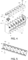
- FIG. 4 is a schematic view illustrating the terminal socket structure according to the embodiment.
- the terminal socket structure has a terminal socket body 41, a terminal cover 42, at least one screw 43 and at least one screw gasket 44, and a fixing pin 45.
- the terminal socket body 41 has at least one screw combining part 411 and a plurality of baffles 412.
- the baffles 412 are disposed to at least two sides of the at least one screw combining part 411.
- the screw combining part 411 is provided to arrange the screw 43.
- the number of the screw combining parts 411 is seven, for example. However, the embodiment is not limited thereto. In actual implementation, the number of the screw combining parts 411 may be more or less than 7.
- the respective screw combining parts 411 are sequentially arranged in a row. However, the embodiment is not limited thereto. In actual implementation, the screw combining parts 411 may be arranged into one row or a plurality of rows disposed in adjacency.
- the terminal cover 42 is fit with the terminal socket body 41 and has a cornice part 421 and a top part 422. At least one through hole 423 is provided on the top part 422, and the at least one through hole 423 corresponds to the at least one screw combining part 411. In other words, the number and location of the through hole 423 correspond to the number and location of the screw combining part 411.
- the through hole 423 By disposing the through hole 423, wiring is able to be carried out with a terminal without the need to remove the terminal cover 42. After the terminal cover 42 is removed, the structure is equivalent to an ordinary fence-type terminal socket. Therefore, different needs of different customers under different cost considerations can be coped with.
- the at least one screw 43 is screw-connected to the at least one screw combining part 411 through the at least one screw gasket 44.
- the numbers of the screw 43 and the screw gasket 44 also correspond to the number of the screw combining part 411.
- the fixing pin 45 is disposed to a side of the terminal socket body 41 opposite to the screw combining part 411.
- FIG. 4 illustrates an example where an extending direction of the fixing pin 45 is perpendicular to an extending direction of the screw 43.
- the embodiment is not limited thereto. In actual implementation, the extending direction of the fixing pin 45 may also be parallel to the extending direction of the screw 43.
- a first rib part 424 is disposed to an inner side of the cornice part 421 of the terminal cover 42 in correspondence with at least one side of each of the screw combining part 411, and the first rib part 424 is fit with at least one of the at least one position limiting part 411.
- FIG. 5 is a schematic view illustrating the first rib part 424 disposed on the terminal cover 42.
- the number of the screw combining part 411 arranged is one, and the baffle 412 is disposed to each of two opposite sides of the screw combining part 411.
- the screw combining parts 411 are configured as a set, and the baffle 412 is disposed to each of two opposite sides of the set of screw combining parts 411, whereas no baffle is disposed between the screw combining parts 411 of the set of screw combining parts 411.
- a cover baffle (not shown) may be disposed between the through holes 423 of the top part 422 of the terminal cover 42 corresponding to the set of screw combining parts 411 to separate the respective screw combining parts 411 of the set of screw combining parts 411.
- the set of screw combining parts 411 includes two screw combining parts 411, for example.
- a second rib part (not shown) may be further disposed to a side of the baffle 412 corresponding to the screw combining part 411.
- the second rib part may be fit with at least one of the at least one position limiting part 411 disposed on the screw gasket 44.
- the screw combining parts 411 are plurality and sequentially arranged in a row, and a baffle 412 is disposed between every two of the screw combining parts 411. Moreover, a baffle 412 is also disposed to a side of the screw combining part 411 adjacent to an edge, where the side is a side adjacent to the edge.
- FIG. 6 is a schematic view illustrating an example of the terminal socket body 41 of the embodiment.
- the number of the screw combining parts 411 of the terminal body 41 is seven, for example.
- the baffle 412 in addition to disposing the baffle 412 between every two of the screw combining parts 411 respectively, the baffle 412 is also disposed to a side of each of the screw combining parts 411 adjacent to two edges, where the side is a side adjacent to the edge. Accordingly, the position of each of the screw combining parts 411 is able to be limited.
- FIG. 7 is a schematic view illustrating another example of the terminal socket body 41 of the embodiment.
- the number of the screw combining parts 411 of the terminal body 41 is also seven, for example.
- a second rib part 413 may be further disposed to at least one side of the baffle 412.
- the second rib part 413 is fit with at least one of the at least one position limiting part 441 disposed on the screw gasket 44. Therefore, by fitting the second rib part 413 disposed on the baffle 412 with the position limiting part 441 disposed on the screw gasket 44, the screw may be further restricted and prevented from being detached, making wiring more convenient.
- the screw combining parts 411 are arranged into a plurality of sets in series, and the baffle 412 is disposed between every two sets of the plurality of sets of the screw combining parts 411. Moreover, the baffle 412 is also disposed to a side of every set of the screw combining parts 411 adjacent to an edge, where the side is a side adjacent to the edge.
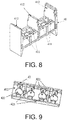
- FIG. 8 is a schematic view illustrating an exemplary embodiment of the terminal socket body 41 of the embodiment
- FIG. 9 is a schematic view illustrating the terminal cover 42 corresponding to the terminal socket body 41.
- the terminal socket body 41 has two sets of the screw combining parts 411, and each set of the screw combining parts 411 includes two screw combining parts 411, for example.
- the baffle 412 is disposed between the two sets of the screw combining parts 411.
- the two sets of the screw combining parts 411 are respectively adjacent to edges. According to FIG.
- the baffle 412 is disposed to a side of the set of the screw combining parts 411 adjacent to a left edge, where the side is a side adjacent to the left edge, while another baffle 412 is disposed to a side of the screw combining parts 411 adjacent to a right edge, where the side is a side adjacent to the right edge.
- a cover baffle 425 may be further disposed between the through holes 423 corresponding to each set of the screw combining parts 411, of the top part 422 on the terminal cover 42, in order to separate the respective screw combining parts 411 in each set of the screw combining parts 411.
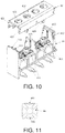
- FIG. 10 is a schematic view illustrating another example of the terminal socket body of the embodiment.
- the terminal socket body 41 similarly has two sets of the screw combining parts 411, each set of the screw combining parts 411 includes two screw combining parts 411, for example.
- the second rib part 413 may be disposed to at least one side of the baffle 412, and the second rib part 413 is fit with at least one of the at least one position limiting part 441 disposed on the screw gasket 44. Therefore, by fitting the second rib part 413 disposed on the baffle 412 with the position limiting part 441 disposed on the screw gasket 44, the screw may be further restricted and prevented from being detached, making wiring more convenient.
- the screw gasket 44 is in a rectangular shape, and the position limiting part 441 is disposed to each of two opposite sides of the screw gasket 44.
- FIG. 11 is a schematic view illustrating the screw gasket 44 of the embodiment.
- the first rib part 424 is disposed to the inner side of the cornice part 421 of the terminal cover 42 in correspondence with each of two sides of each of the screw combining parts 411, as shown in FIGs. 4 and 5 , and the position of the screw 43 is limited by fitting the two first rib parts 424 with the two position limiting parts 441 disposed on the screw gasket 44.
- the screw gasket 44 is in a rectangular shape, and the position limiting part 441 is disposed to each of four sides of the screw gasket 44.
- FIG. 12 is a schematic view illustrating an example of a status in which the screw gasket 44 and the screw are assembled.
- the first rib part 424 is disposed to the inner side of the cornice part 421 of the terminal cover 42 in correspondence with each of the two sides of each of the screw combining parts 411, as shown in FIGs. 4 and 5
- the second rib part 413 is disposed to each of two sides of the baffle 412, as shown in FIGs. 7 and 10 , the position of the screw 43 is limited by fitting the first rib parts 424 and the second rib parts 413 with the four position limiting parts 441 disposed on the screw gasket 44.
- an inner diameter of the through hole 423 may be less than an outer diameter of the screw gasket 44.
- FIG. 13 is a cross-sectional view illustrating the terminal socket structure. As shown in FIG. 13 , by arranging an inner diameter ⁇ A of the through hole 423 to be less than an outer diameter ⁇ B of the screw gasket 44, it is ensured that the screw is not detached from the terminal socket body 41. Meanwhile, it is also ensured that, after the screw 43 is completely backed out, the second rib part 413 disposed on the terminal socket body 41 and/or the first rib part 424 disposed on the terminal cover 42 are able to effectively guide the direction of the screw 43, and an adequate distance is provided so that wiring of the terminal is ensured.
- terminal cover 42 and the terminal socket body 41 may be combined through engagement.
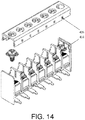
- a positioning aperture 426 is disposed to an outer side of the cornice part 421 of the terminal cover 42 at a position corresponding to each of the baffles 412.
- a protrusion 414 is disposed to at least one end of the baffle 412 corresponding to the positioning aperture 426.
- the terminal socket body and the screw gasket are designed to prevent the screw from being detached and to make wiring more convenient (i.e., having directional guidance).
- wiring with the terminal is enabled without the need to remove the terminal cover.
- the terminal socket structure is equivalent to an ordinary terminal socket, so the different cost considerations of different customers can be coped with.
- Embodiment 2 of the invention provides a power apparatus.
- the power apparatus includes the terminal socket structure according to Embodiment 1. Since the descriptions about the terminal socket structure have been made in Embodiment 1, said descriptions are incorporated herein and shall thus not be repeated in the following.
- the terminal socket structure of Embodiment 1 is adopted to prevent the screw from being detached, and wiring is thus more convenient.
Landscapes
- Engineering & Computer Science (AREA)
- General Engineering & Computer Science (AREA)
- Mechanical Engineering (AREA)
- Connections Arranged To Contact A Plurality Of Conductors (AREA)
- Connections By Means Of Piercing Elements, Nuts, Or Screws (AREA)
Abstract
Description
- The invention relates to the field of power supply, and particularly relates to a terminal socket structure and a power apparatus having the terminal socket structure.
- Conventional terminal socket structures can normally be divided into the following types:
Type 1, those having screws with a deformed thread; Type 2, those having terminal sockets with an integrally formed plastic cover; andType 3, those having a terminal cover to avoid detachment. -
FIG. 1 is a schematic view illustrating a terminal socket structure of Type 1 (shown as ① inFIG. 1 ). As shown inFIG. 1 , through a deformation process at a bottom part of a screw, it is ensured that the screw and a fixing pin are unable to be detached from each other, so as to avoid detachment. However,Type 1 cannot employ O-type terminal wiring. -
FIG. 2 is a schematic view illustrating a terminal socket of Type 2 (shown as ② inFIG. 1 ). As shown inFIG. 2 , by integrally forming a plastic cover, the terminal socket body is able to limit a size of the screw to ensure that the screw is unable to be backed out, thereby avoiding detachment. However, there is no directional guidance during wiring of the screw in Type 2, making wiring more difficult. In addition, the cost of the terminal socket is higher. -
FIG. 3 is a schematic view illustrating a terminal socket structure of Type 3 (shown as ③ inFIG. 1 ). As shown inFIG. 3 , a size of a screw head is limited by a terminal cover. Since an inner diameter φ A of a plastic cover body (or a terminal cover) is less than an outer diameter φ B of a screw gasket, the screw is limited and unable to be backed out. However, similar to Type 2, there is no directional guidance during wiring of the screw inType 3, so wiring is more difficult. Moreover, when wiring with a terminal, the terminal cover needs to be removed before wiring is able to be carried out. - It should be noted that the introduction to the technical background is only provided to more clearly and comprehensively describe the technical solution of the invention and facilitate the understanding of people skilled in the art. The above technical solutions shall not be considered as well-known to people skilled in the art simply because the technical solutions are described in the section of Description of Related Art of the invention.
- In order to resolve the problem of existing terminal block structure, embodiments of the invention provides a terminal socket structure and a power apparatus having the terminal socket structure to prevent a screw from being detached from the terminal socket.
- According to a first aspect of an embodiment of the invention, a terminal socket structure is provided. The terminal socket structure includes: a terminal socket body, having at least one screw combining part and a plurality of baffles, wherein the baffles are disposed to at least two sides of the at least one screw combining part; a terminal cover, fitting with the terminal socket body and having a cornice part and a top part, wherein at least one through hole is disposed on the top part, and the at least one through hole corresponds to the at least one screw combining part; at least one screw and at least one screw gasket, wherein the at least one screw is screw-connected to the at least one screw combining part through the at least one screw gasket; and a fixing pin, disposed to a side of the terminal socket body opposite to the screw combining part, wherein: at least one position limiting part is disposed to an outer circumference of the screw gasket, a first rib part is disposed to an inner side of the cornice part of the terminal cover in correspondence with at least one side of each of the at least one screw combining part, and the first rib part is fit with at least one of the at least one position limiting part.
- According to a second aspect of an embodiment of the invention, a power apparatus is provided. The power apparatus includes the terminal socket structure according to the first aspect.
- In the terminal socket structure according to the embodiments of the invention, the terminal socket body and the screw gasket are improved in designs to prevent the screw from being detached and to make wiring more convenient (i.e., having directional guidance). In addition, wiring with the terminal is enabled without the need to remove the terminal cover. Moreover, after removing the terminal cover, the terminal socket structure is equivalent to an ordinary terminal socket, so the different cost considerations of different customers can be coped with.
- Specific embodiments of the invention are disclosed in detail with reference to the following descriptions and the accompanying drawings. The descriptions clearly describe examples in which the principle of the invention is applicable. However, it should be understood that the scope of the embodiments of the invention shall not be limited thereto. The embodiments of the invention may cover various modifications, changes, and equivalents without departing from the spirit and terms of the annexed claims.
- The description(s) for an embodiment and/or a disclosed feature(s) may be applied in one or more embodiments in an identical or similar way, combined with a feature in another embodiment, or replace a feature in another embodiment.
- It should be noted that, throughout the text, terms such as "comprise/include" refer to the presence of a feature, an assembly, a step, or a component, but do not exclude the presence or addition of another feature, another assembly, another step or another component.
- The accompanying drawings are included to provide a further understanding of the invention, and are incorporated in and constitute a part of this specification. The drawings illustrate embodiments of the invention and, together with the description, serve to explain the principles of the invention.
-
FIG. 1 is a schematic view illustrating a terminal socket structure including a screw with a deformed thread. -
FIG. 2 is a schematic view illustrating a terminal socket structure with an integrally formed plastic cover. -
FIG. 3 is a schematic view illustrating a terminal socket structure with a terminal cover preventing detachment. -
FIG. 4 is a schematic view illustrating a terminal socket structure according toEmbodiment 1. -
FIG. 5 is a schematic view illustrating a terminal cover according toEmbodiment 1. -
FIG. 6 is a schematic view illustrating an example of a terminal socket body. -
FIG. 7 is a schematic view illustrating another example of a terminal socket body. -
FIG. 8 is a schematic view illustrating yet another example of a terminal socket body. -
FIG. 9 is a schematic view illustrating a terminal cover corresponding to the terminal socket body ofFIG. 8 . -
FIG. 10 is a schematic view illustrating another example of a terminal socket structure. -
FIG. 11 is a schematic view illustrating an example of a screw gasket. -
FIG. 12 is a schematic view illustrating another example of a status in which a screw gasket and a screw are assembled. -
FIG. 13 is a schematic view illustrating a cross section of a terminal socket structure. -
FIG. 14 is a schematic view illustrating an engagement configuration of a terminal socket structure. - Reference will now be made in detail to the present preferred embodiments of the invention, examples of which are illustrated in the accompanying drawings. Wherever possible, the same reference numbers are used in the drawings and the description to refer to the same or like parts.
- A terminal socket structure is provided according to
Embodiment 1 of the invention. -
FIG. 4 is a schematic view illustrating the terminal socket structure according to the embodiment. As shown inFIG. 4 , the terminal socket structure has aterminal socket body 41, aterminal cover 42, at least onescrew 43 and at least onescrew gasket 44, and afixing pin 45. - In the embodiment, as shown in
FIG. 4 , theterminal socket body 41 has at least onescrew combining part 411 and a plurality ofbaffles 412. Thebaffles 412 are disposed to at least two sides of the at least onescrew combining part 411. In the embodiment, namely, thescrew combining part 411 is provided to arrange thescrew 43. InFIG. 4 , the number of thescrew combining parts 411 is seven, for example. However, the embodiment is not limited thereto. In actual implementation, the number of thescrew combining parts 411 may be more or less than 7. Besides, inFIG. 4 , the respectivescrew combining parts 411 are sequentially arranged in a row. However, the embodiment is not limited thereto. In actual implementation, thescrew combining parts 411 may be arranged into one row or a plurality of rows disposed in adjacency. - In the embodiment, as shown in
FIG. 4 , theterminal cover 42 is fit with theterminal socket body 41 and has acornice part 421 and atop part 422. At least one throughhole 423 is provided on thetop part 422, and the at least one throughhole 423 corresponds to the at least onescrew combining part 411. In other words, the number and location of the throughhole 423 correspond to the number and location of thescrew combining part 411. By disposing the throughhole 423, wiring is able to be carried out with a terminal without the need to remove theterminal cover 42. After theterminal cover 42 is removed, the structure is equivalent to an ordinary fence-type terminal socket. Therefore, different needs of different customers under different cost considerations can be coped with. - In the embodiment, as shown in
FIG. 4 , the at least onescrew 43 is screw-connected to the at least onescrew combining part 411 through the at least onescrew gasket 44. In other words, the numbers of thescrew 43 and thescrew gasket 44 also correspond to the number of thescrew combining part 411. - In the embodiment, as shown in
FIG. 4 , the fixingpin 45 is disposed to a side of theterminal socket body 41 opposite to thescrew combining part 411.FIG. 4 illustrates an example where an extending direction of the fixingpin 45 is perpendicular to an extending direction of thescrew 43. However, the embodiment is not limited thereto. In actual implementation, the extending direction of the fixingpin 45 may also be parallel to the extending direction of thescrew 43. - In the embodiment, what differs from a conventional terminal socket structure is that, as shown in
FIG. 4 , at least oneposition limiting part 441 is disposed to an outer circumference of thescrew gasket 44. Besides, afirst rib part 424 is disposed to an inner side of thecornice part 421 of theterminal cover 42 in correspondence with at least one side of each of thescrew combining part 411, and thefirst rib part 424 is fit with at least one of the at least oneposition limiting part 411. -
FIG. 5 is a schematic view illustrating thefirst rib part 424 disposed on theterminal cover 42. With the structure, by fitting thefirst rib part 424 disposed on theterminal cover 42 with theposition limiting part 441 disposed on thescrew gasket 44, the screw is restricted and prevented from being detached. Moreover, wiring also becomes easier (due to directional guidance provided). - In an exemplary example of the embodiment, the number of the
screw combining part 411 arranged is one, and thebaffle 412 is disposed to each of two opposite sides of thescrew combining part 411. - In another exemplary example of the embodiment, the
screw combining parts 411 are configured as a set, and thebaffle 412 is disposed to each of two opposite sides of the set ofscrew combining parts 411, whereas no baffle is disposed between thescrew combining parts 411 of the set ofscrew combining parts 411. Moreover, a cover baffle (not shown) may be disposed between the throughholes 423 of thetop part 422 of theterminal cover 42 corresponding to the set ofscrew combining parts 411 to separate the respectivescrew combining parts 411 of the set ofscrew combining parts 411. In the embodiment, the set ofscrew combining parts 411 includes twoscrew combining parts 411, for example. - In the two embodiments, a second rib part (not shown) may be further disposed to a side of the
baffle 412 corresponding to thescrew combining part 411. The second rib part may be fit with at least one of the at least oneposition limiting part 411 disposed on thescrew gasket 44. Hence, by fitting the second rib part disposed on thebaffle 412 with theposition limiting part 441 disposed on thescrew gasket 44, the screw may be further restricted and prevented from being detached, making wiring more convenient. - In yet another exemplary example of the embodiment, the
screw combining parts 411 are plurality and sequentially arranged in a row, and abaffle 412 is disposed between every two of thescrew combining parts 411. Moreover, abaffle 412 is also disposed to a side of thescrew combining part 411 adjacent to an edge, where the side is a side adjacent to the edge. -
FIG. 6 is a schematic view illustrating an example of theterminal socket body 41 of the embodiment. In the example, the number of thescrew combining parts 411 of theterminal body 41 is seven, for example. As shown inFIG. 6 , in the example, in addition to disposing thebaffle 412 between every two of thescrew combining parts 411 respectively, thebaffle 412 is also disposed to a side of each of thescrew combining parts 411 adjacent to two edges, where the side is a side adjacent to the edge. Accordingly, the position of each of thescrew combining parts 411 is able to be limited. -
FIG. 7 is a schematic view illustrating another example of theterminal socket body 41 of the embodiment. In the exemplary example, the number of thescrew combining parts 411 of theterminal body 41 is also seven, for example. As shown inFIG. 7 , what differs from the example inFIG. 6 is that, in the example, asecond rib part 413 may be further disposed to at least one side of thebaffle 412. Thesecond rib part 413 is fit with at least one of the at least oneposition limiting part 441 disposed on thescrew gasket 44. Therefore, by fitting thesecond rib part 413 disposed on thebaffle 412 with theposition limiting part 441 disposed on thescrew gasket 44, the screw may be further restricted and prevented from being detached, making wiring more convenient. - In yet another exemplary example of the embodiment, the
screw combining parts 411 are arranged into a plurality of sets in series, and thebaffle 412 is disposed between every two sets of the plurality of sets of thescrew combining parts 411. Moreover, thebaffle 412 is also disposed to a side of every set of thescrew combining parts 411 adjacent to an edge, where the side is a side adjacent to the edge. -
FIG. 8 is a schematic view illustrating an exemplary embodiment of theterminal socket body 41 of the embodiment,FIG. 9 is a schematic view illustrating theterminal cover 42 corresponding to theterminal socket body 41. In the example, theterminal socket body 41 has two sets of thescrew combining parts 411, and each set of thescrew combining parts 411 includes twoscrew combining parts 411, for example. As shown inFIGs. 8 and 9 , thebaffle 412 is disposed between the two sets of thescrew combining parts 411. In addition, the two sets of thescrew combining parts 411 are respectively adjacent to edges. According toFIG. 8 , thebaffle 412 is disposed to a side of the set of thescrew combining parts 411 adjacent to a left edge, where the side is a side adjacent to the left edge, while anotherbaffle 412 is disposed to a side of thescrew combining parts 411 adjacent to a right edge, where the side is a side adjacent to the right edge. In the embodiment, as shown inFIG. 9 , acover baffle 425 may be further disposed between the throughholes 423 corresponding to each set of thescrew combining parts 411, of thetop part 422 on theterminal cover 42, in order to separate the respectivescrew combining parts 411 in each set of thescrew combining parts 411. -
FIG. 10 is a schematic view illustrating another example of the terminal socket body of the embodiment. In the example, theterminal socket body 41 similarly has two sets of thescrew combining parts 411, each set of thescrew combining parts 411 includes twoscrew combining parts 411, for example. As shown inFIG. 10 , what differs from the examples inFIGs. 8 and 9 is that, in the example, thesecond rib part 413 may be disposed to at least one side of thebaffle 412, and thesecond rib part 413 is fit with at least one of the at least oneposition limiting part 441 disposed on thescrew gasket 44. Therefore, by fitting thesecond rib part 413 disposed on thebaffle 412 with theposition limiting part 441 disposed on thescrew gasket 44, the screw may be further restricted and prevented from being detached, making wiring more convenient. - In an exemplary example of the embodiment, the
screw gasket 44 is in a rectangular shape, and theposition limiting part 441 is disposed to each of two opposite sides of thescrew gasket 44.FIG. 11 is a schematic view illustrating thescrew gasket 44 of the embodiment. In the embodiment, thefirst rib part 424 is disposed to the inner side of thecornice part 421 of theterminal cover 42 in correspondence with each of two sides of each of thescrew combining parts 411, as shown inFIGs. 4 and 5 , and the position of thescrew 43 is limited by fitting the twofirst rib parts 424 with the twoposition limiting parts 441 disposed on thescrew gasket 44. - In another exemplary example of the embodiment, the
screw gasket 44 is in a rectangular shape, and theposition limiting part 441 is disposed to each of four sides of thescrew gasket 44.FIG. 12 is a schematic view illustrating an example of a status in which thescrew gasket 44 and the screw are assembled. In the example, thefirst rib part 424 is disposed to the inner side of thecornice part 421 of theterminal cover 42 in correspondence with each of the two sides of each of thescrew combining parts 411, as shown inFIGs. 4 and 5 , moreover, thesecond rib part 413 is disposed to each of two sides of thebaffle 412, as shown inFIGs. 7 and10 , the position of thescrew 43 is limited by fitting thefirst rib parts 424 and thesecond rib parts 413 with the fourposition limiting parts 441 disposed on thescrew gasket 44. - In the embodiment, an inner diameter of the through
hole 423 may be less than an outer diameter of thescrew gasket 44.FIG. 13 is a cross-sectional view illustrating the terminal socket structure. As shown inFIG. 13 , by arranging an inner diameter ϕ A of the throughhole 423 to be less than an outer diameter ϕ B of thescrew gasket 44, it is ensured that the screw is not detached from theterminal socket body 41. Meanwhile, it is also ensured that, after thescrew 43 is completely backed out, thesecond rib part 413 disposed on theterminal socket body 41 and/or thefirst rib part 424 disposed on theterminal cover 42 are able to effectively guide the direction of thescrew 43, and an adequate distance is provided so that wiring of the terminal is ensured. - In the embodiment, the
terminal cover 42 and theterminal socket body 41 may be combined through engagement. - In an embodiment, as shown in
FIG. 14 , apositioning aperture 426 is disposed to an outer side of thecornice part 421 of theterminal cover 42 at a position corresponding to each of thebaffles 412. Aprotrusion 414 is disposed to at least one end of thebaffle 412 corresponding to thepositioning aperture 426. By inserting theprotrusion 414 into thepositioning aperture 426, theterminal cover 42 is engaged with theterminal socket body 41. Accordingly, the components may be assembled or detached based on needs. - In the terminal socket structure according to the embodiments of the invention, the terminal socket body and the screw gasket are designed to prevent the screw from being detached and to make wiring more convenient (i.e., having directional guidance). In addition, wiring with the terminal is enabled without the need to remove the terminal cover. Moreover, after removing the terminal cover, the terminal socket structure is equivalent to an ordinary terminal socket, so the different cost considerations of different customers can be coped with.
- Embodiment 2 of the invention provides a power apparatus. The power apparatus includes the terminal socket structure according to
Embodiment 1. Since the descriptions about the terminal socket structure have been made inEmbodiment 1, said descriptions are incorporated herein and shall thus not be repeated in the following. - In the power apparatus of the embodiment, the terminal socket structure of
Embodiment 1 is adopted to prevent the screw from being detached, and wiring is thus more convenient. - It will be apparent to those skilled in the art that various modifications and variations can be made to the structure of the present invention without departing from the scope or spirit of the invention. In view of the foregoing, it is intended that the present invention cover modifications and variations of this invention provided they fall within the scope of the following claims and their equivalents.
Claims (11)
- A terminal socket structure, comprising:a terminal socket body (41), having at least one screw combining part (411) and a plurality of baffles (412), wherein the baffles are disposed to at least two sides of the at least one screw combining part;a terminal cover (42), fit with the terminal socket body and having a cornice part (421) and a top part (422), wherein at least one through hole (423) is disposed on the top part, and the at least one through hole corresponds to the at least one screw combining part;at least one screw (43) and at least one screw gasket (44), wherein the at least one screw is screw-connected to the at least one screw combining part through the at least one screw gasket; anda fixing pin (45), disposed to a side of the terminal socket body opposite to the screw combining part,wherein:at least one position limiting part is disposed to an outer circumference of the screw gasket, a first rib part (424) is disposed to an inner side of the cornice part of the terminal cover in correspondence with at least one side of each of the at least one screw combining part, and the first rib part is fit with at least one of the at least one position limiting part (441).
- The terminal socket structure as claimed in claim 1, wherein:the at least one screw combining part (411) is arranged in one screw combining part or as a set of screw combining parts, and the baffle (412) is disposed to each of two opposite sides of the one screw combining part or the set of screw combining parts; orthe at least one screw combining part (411) is sequentially arranged in a plurality of screw combining parts or a plurality of sets of screw combining parts, and the baffle (412) is disposed between every two of the plurality of screw combining parts or every two sets of the plurality of sets of screw combining parts, and the baffle is also disposed to a side of a screw combining part adjacent to an edge, where the side is a side adjacent to the edge.
- The terminal socket structure as claimed in claim 2, wherein each of the sets of screw combining parts (411) comprises two screw combining parts.
- The terminal socket structure as claimed in claim 2, wherein a cover baffle (425) is disposed between the through holes (423) of the top part (422) of the terminal cover in correspondence each of the sets of screw combining parts.
- The terminal socket structure as claimed in any one of claims 1 to 4, wherein a second rib part (413) is disposed to at least one side of the baffle (412), and the second rib part is fit with at least one of the at least one position limiting part (441).
- The terminal socket structure as claimed in claim 1, wherein the at least one screw gasket (44) is in a rectangular shape, the position limiting part (441) is disposed to each of two opposite sides of the at least one screw gasket, the first rib part (424) is disposed to the inner side of the cornice part (421) of the terminal cover (42) in correspondence with each of two sides of each of the at least one screw combining part (411), and the first rib parts are fit with the position limiting parts.
- The terminal socket structure as claimed in claim 5, wherein the at least one screw gasket (44) is in a rectangular shape, the position limiting part (441) is disposed to each of four sides of the at least one screw gasket, the first rib part (424) is disposed to the inner side of the cornice part of the terminal cover (42) in correspondence with each of two sides of each of the at least one screw combining parts (411), the first rib parts are fit with two of the position limiting parts, the second rib part (413) is disposed to each of two sides of the baffle (412), and the second rib parts are fit with the other two of the position limiting parts.
- The terminal socket structure as claimed in claim 1, wherein an inner diameter of the at least one through hole (423) is less than an outer diameter of the at least one screw gasket (44).
- The terminal socket structure as claimed in claim 1, wherein the terminal cover (42) is fit with the terminal socket body (41) through engagement.
- The terminal socket structure as claimed in claim 9, wherein a positioning aperture (426) is disposed to an outer side of the cornice part (421) of the terminal cover (42) at a position corresponding to each of the baffles (412), a protrusion (414) is disposed to at least one end of the baffles corresponding to the positioning aperture, and the terminal cover is engaged with the terminal socket body by inserting the protrusion into the positioning aperture.
- A power apparatus, comprising the terminal socket structure according to any one of claims 1 to 10.
Applications Claiming Priority (1)
| Application Number | Priority Date | Filing Date | Title |
|---|---|---|---|
| CN201621115519.5U CN206259511U (en) | 2016-10-12 | 2016-10-12 | Terminal table structure and the supply unit with the terminal table structure |
Publications (2)
| Publication Number | Publication Date |
|---|---|
| EP3309903A1 true EP3309903A1 (en) | 2018-04-18 |
| EP3309903B1 EP3309903B1 (en) | 2020-01-15 |
Family
ID=59022532
Family Applications (1)
| Application Number | Title | Priority Date | Filing Date |
|---|---|---|---|
| EP17191580.4A Active EP3309903B1 (en) | 2016-10-12 | 2017-09-18 | Terminal socket structure and power apparatus having the same |
Country Status (3)
| Country | Link |
|---|---|
| EP (1) | EP3309903B1 (en) |
| JP (1) | JP6439842B2 (en) |
| CN (1) | CN206259511U (en) |
Families Citing this family (4)
| Publication number | Priority date | Publication date | Assignee | Title |
|---|---|---|---|---|
| CN106369037B (en) * | 2016-11-28 | 2018-05-18 | 苏州思科赛德电子科技有限公司 | Fence type connecting terminal platform screw anti-drop device |
| CN107394491A (en) * | 2017-07-21 | 2017-11-24 | 上海航天科工电器研究院有限公司 | A kind of connector plug of anti-screw back |
| KR101941666B1 (en) * | 2018-09-11 | 2019-01-23 | 우창전력(주) | Terminal unit of power system control circuit for transformer equipment |
| KR102684808B1 (en) * | 2020-03-25 | 2024-07-11 | 주식회사 엘지에너지솔루션 | Battery Pack with a handle which has a loose stopper |
Citations (5)
| Publication number | Priority date | Publication date | Assignee | Title |
|---|---|---|---|---|
| JPS59166368U (en) * | 1983-04-22 | 1984-11-07 | オムロン株式会社 | Terminal block |
| JPH08167434A (en) * | 1994-10-11 | 1996-06-25 | Fuji Electric Co Ltd | Terminal equipment for electrical equipment |
| JP2001085082A (en) * | 1999-09-13 | 2001-03-30 | Omron Corp | Terminal block |
| US20130309917A1 (en) * | 2012-05-16 | 2013-11-21 | Shang Tsai Wu | Wire-grasping structure for terminal block |
| US9093761B1 (en) * | 2014-03-12 | 2015-07-28 | Dinkle Enterprise Co., Ltd. | Terminal block structure |
Family Cites Families (5)
| Publication number | Priority date | Publication date | Assignee | Title |
|---|---|---|---|---|
| JPS5158889U (en) * | 1974-11-05 | 1976-05-10 | ||
| JPS5879872U (en) * | 1981-11-20 | 1983-05-30 | 東芝プラント建設株式会社 | Terminal block |
| JPS63196569U (en) * | 1987-06-04 | 1988-12-19 | ||
| JPH0326976U (en) * | 1989-07-26 | 1991-03-19 | ||
| JP3930470B2 (en) * | 2003-10-07 | 2007-06-13 | エムデン無線工業株式会社 | Terminal block device |
-
2016
- 2016-10-12 CN CN201621115519.5U patent/CN206259511U/en active Active
-
2017
- 2017-09-14 JP JP2017176283A patent/JP6439842B2/en active Active
- 2017-09-18 EP EP17191580.4A patent/EP3309903B1/en active Active
Patent Citations (5)
| Publication number | Priority date | Publication date | Assignee | Title |
|---|---|---|---|---|
| JPS59166368U (en) * | 1983-04-22 | 1984-11-07 | オムロン株式会社 | Terminal block |
| JPH08167434A (en) * | 1994-10-11 | 1996-06-25 | Fuji Electric Co Ltd | Terminal equipment for electrical equipment |
| JP2001085082A (en) * | 1999-09-13 | 2001-03-30 | Omron Corp | Terminal block |
| US20130309917A1 (en) * | 2012-05-16 | 2013-11-21 | Shang Tsai Wu | Wire-grasping structure for terminal block |
| US9093761B1 (en) * | 2014-03-12 | 2015-07-28 | Dinkle Enterprise Co., Ltd. | Terminal block structure |
Also Published As
| Publication number | Publication date |
|---|---|
| JP2018063941A (en) | 2018-04-19 |
| EP3309903B1 (en) | 2020-01-15 |
| CN206259511U (en) | 2017-06-16 |
| JP6439842B2 (en) | 2018-12-19 |
Similar Documents
| Publication | Publication Date | Title |
|---|---|---|
| EP3309903B1 (en) | Terminal socket structure and power apparatus having the same | |
| US20210053761A1 (en) | Finger guard member and finger guard member coupling structure | |
| DE112014003014B4 (en) | connector and charging connector | |
| US10305269B2 (en) | Cable/line lead-in | |
| US8247709B2 (en) | Method of making a replaceable knockout part in a metal panel and systems thereof | |
| US20190334278A1 (en) | Holding frame for a plug connector and methods of populating same | |
| US10704587B2 (en) | Captive fastener assembly | |
| RU2702338C2 (en) | Plate with pressure-tested contacts and connector | |
| CN105375167A (en) | Coaxial connector | |
| DE112014005835T5 (en) | Electrical cable connector and connector assembly | |
| US20130302663A1 (en) | Assembled battery | |
| US10511129B1 (en) | Power connector | |
| ES2729667T3 (en) | Arrangement of several locking pins for a module | |
| US9793645B2 (en) | Seal member and connector | |
| US9859646B2 (en) | Electrical connector and method for mounting electrical connector on circuit board | |
| US20030052234A1 (en) | Cable mounting structure | |
| US9698552B2 (en) | Connector | |
| US20200132095A1 (en) | Fool-proof housing | |
| US8986035B2 (en) | Securing member for a connector | |
| JP2016004787A (en) | Connector housing | |
| JPWO2016063377A1 (en) | connector | |
| CN205051085U (en) | Electric connector assembly | |
| JP6451996B2 (en) | connector | |
| KR20170015148A (en) | Fastener | |
| US20150366109A1 (en) | Shielding cage with overinsertion prevention aspect |
Legal Events
| Date | Code | Title | Description |
|---|---|---|---|
| PUAI | Public reference made under article 153(3) epc to a published international application that has entered the european phase |
Free format text: ORIGINAL CODE: 0009012 |
|
| STAA | Information on the status of an ep patent application or granted ep patent |
Free format text: STATUS: REQUEST FOR EXAMINATION WAS MADE |
|
| 17P | Request for examination filed |
Effective date: 20170918 |
|
| AK | Designated contracting states |
Kind code of ref document: A1 Designated state(s): AL AT BE BG CH CY CZ DE DK EE ES FI FR GB GR HR HU IE IS IT LI LT LU LV MC MK MT NL NO PL PT RO RS SE SI SK SM TR |
|
| AX | Request for extension of the european patent |
Extension state: BA ME |
|
| RBV | Designated contracting states (corrected) |
Designated state(s): AL AT BE BG CH CY CZ DE DK EE ES FI FR GB GR HR HU IE IS IT LI LT LU LV MC MK MT NL NO PL PT RO RS SE SI SK SM TR |
|
| STAA | Information on the status of an ep patent application or granted ep patent |
Free format text: STATUS: EXAMINATION IS IN PROGRESS |
|
| 17Q | First examination report despatched |
Effective date: 20190515 |
|
| GRAP | Despatch of communication of intention to grant a patent |
Free format text: ORIGINAL CODE: EPIDOSNIGR1 |
|
| STAA | Information on the status of an ep patent application or granted ep patent |
Free format text: STATUS: GRANT OF PATENT IS INTENDED |
|
| INTG | Intention to grant announced |
Effective date: 20190912 |
|
| GRAS | Grant fee paid |
Free format text: ORIGINAL CODE: EPIDOSNIGR3 |
|
| GRAA | (expected) grant |
Free format text: ORIGINAL CODE: 0009210 |
|
| STAA | Information on the status of an ep patent application or granted ep patent |
Free format text: STATUS: THE PATENT HAS BEEN GRANTED |
|
| AK | Designated contracting states |
Kind code of ref document: B1 Designated state(s): AL AT BE BG CH CY CZ DE DK EE ES FI FR GB GR HR HU IE IS IT LI LT LU LV MC MK MT NL NO PL PT RO RS SE SI SK SM TR |
|
| REG | Reference to a national code |
Ref country code: CH Ref legal event code: EP Ref country code: GB Ref legal event code: FG4D |
|
| REG | Reference to a national code |
Ref country code: IE Ref legal event code: FG4D |
|
| REG | Reference to a national code |
Ref country code: DE Ref legal event code: R096 Ref document number: 602017010871 Country of ref document: DE |
|
| REG | Reference to a national code |
Ref country code: AT Ref legal event code: REF Ref document number: 1225985 Country of ref document: AT Kind code of ref document: T Effective date: 20200215 |
|
| REG | Reference to a national code |
Ref country code: NL Ref legal event code: MP Effective date: 20200115 |
|
| REG | Reference to a national code |
Ref country code: LT Ref legal event code: MG4D |
|
| PG25 | Lapsed in a contracting state [announced via postgrant information from national office to epo] |
Ref country code: RS Free format text: LAPSE BECAUSE OF FAILURE TO SUBMIT A TRANSLATION OF THE DESCRIPTION OR TO PAY THE FEE WITHIN THE PRESCRIBED TIME-LIMIT Effective date: 20200115 Ref country code: PT Free format text: LAPSE BECAUSE OF FAILURE TO SUBMIT A TRANSLATION OF THE DESCRIPTION OR TO PAY THE FEE WITHIN THE PRESCRIBED TIME-LIMIT Effective date: 20200607 Ref country code: NO Free format text: LAPSE BECAUSE OF FAILURE TO SUBMIT A TRANSLATION OF THE DESCRIPTION OR TO PAY THE FEE WITHIN THE PRESCRIBED TIME-LIMIT Effective date: 20200415 Ref country code: FI Free format text: LAPSE BECAUSE OF FAILURE TO SUBMIT A TRANSLATION OF THE DESCRIPTION OR TO PAY THE FEE WITHIN THE PRESCRIBED TIME-LIMIT Effective date: 20200115 Ref country code: NL Free format text: LAPSE BECAUSE OF FAILURE TO SUBMIT A TRANSLATION OF THE DESCRIPTION OR TO PAY THE FEE WITHIN THE PRESCRIBED TIME-LIMIT Effective date: 20200115 |
|
| PG25 | Lapsed in a contracting state [announced via postgrant information from national office to epo] |
Ref country code: IS Free format text: LAPSE BECAUSE OF FAILURE TO SUBMIT A TRANSLATION OF THE DESCRIPTION OR TO PAY THE FEE WITHIN THE PRESCRIBED TIME-LIMIT Effective date: 20200515 Ref country code: BG Free format text: LAPSE BECAUSE OF FAILURE TO SUBMIT A TRANSLATION OF THE DESCRIPTION OR TO PAY THE FEE WITHIN THE PRESCRIBED TIME-LIMIT Effective date: 20200415 Ref country code: HR Free format text: LAPSE BECAUSE OF FAILURE TO SUBMIT A TRANSLATION OF THE DESCRIPTION OR TO PAY THE FEE WITHIN THE PRESCRIBED TIME-LIMIT Effective date: 20200115 Ref country code: SE Free format text: LAPSE BECAUSE OF FAILURE TO SUBMIT A TRANSLATION OF THE DESCRIPTION OR TO PAY THE FEE WITHIN THE PRESCRIBED TIME-LIMIT Effective date: 20200115 Ref country code: GR Free format text: LAPSE BECAUSE OF FAILURE TO SUBMIT A TRANSLATION OF THE DESCRIPTION OR TO PAY THE FEE WITHIN THE PRESCRIBED TIME-LIMIT Effective date: 20200416 Ref country code: LV Free format text: LAPSE BECAUSE OF FAILURE TO SUBMIT A TRANSLATION OF THE DESCRIPTION OR TO PAY THE FEE WITHIN THE PRESCRIBED TIME-LIMIT Effective date: 20200115 |
|
| REG | Reference to a national code |
Ref country code: DE Ref legal event code: R097 Ref document number: 602017010871 Country of ref document: DE |
|
| PG25 | Lapsed in a contracting state [announced via postgrant information from national office to epo] |
Ref country code: DK Free format text: LAPSE BECAUSE OF FAILURE TO SUBMIT A TRANSLATION OF THE DESCRIPTION OR TO PAY THE FEE WITHIN THE PRESCRIBED TIME-LIMIT Effective date: 20200115 Ref country code: SM Free format text: LAPSE BECAUSE OF FAILURE TO SUBMIT A TRANSLATION OF THE DESCRIPTION OR TO PAY THE FEE WITHIN THE PRESCRIBED TIME-LIMIT Effective date: 20200115 Ref country code: EE Free format text: LAPSE BECAUSE OF FAILURE TO SUBMIT A TRANSLATION OF THE DESCRIPTION OR TO PAY THE FEE WITHIN THE PRESCRIBED TIME-LIMIT Effective date: 20200115 Ref country code: SK Free format text: LAPSE BECAUSE OF FAILURE TO SUBMIT A TRANSLATION OF THE DESCRIPTION OR TO PAY THE FEE WITHIN THE PRESCRIBED TIME-LIMIT Effective date: 20200115 Ref country code: CZ Free format text: LAPSE BECAUSE OF FAILURE TO SUBMIT A TRANSLATION OF THE DESCRIPTION OR TO PAY THE FEE WITHIN THE PRESCRIBED TIME-LIMIT Effective date: 20200115 Ref country code: ES Free format text: LAPSE BECAUSE OF FAILURE TO SUBMIT A TRANSLATION OF THE DESCRIPTION OR TO PAY THE FEE WITHIN THE PRESCRIBED TIME-LIMIT Effective date: 20200115 Ref country code: RO Free format text: LAPSE BECAUSE OF FAILURE TO SUBMIT A TRANSLATION OF THE DESCRIPTION OR TO PAY THE FEE WITHIN THE PRESCRIBED TIME-LIMIT Effective date: 20200115 Ref country code: LT Free format text: LAPSE BECAUSE OF FAILURE TO SUBMIT A TRANSLATION OF THE DESCRIPTION OR TO PAY THE FEE WITHIN THE PRESCRIBED TIME-LIMIT Effective date: 20200115 |
|
| REG | Reference to a national code |
Ref country code: AT Ref legal event code: MK05 Ref document number: 1225985 Country of ref document: AT Kind code of ref document: T Effective date: 20200115 |
|
| PLBE | No opposition filed within time limit |
Free format text: ORIGINAL CODE: 0009261 |
|
| STAA | Information on the status of an ep patent application or granted ep patent |
Free format text: STATUS: NO OPPOSITION FILED WITHIN TIME LIMIT |
|
| 26N | No opposition filed |
Effective date: 20201016 |
|
| PG25 | Lapsed in a contracting state [announced via postgrant information from national office to epo] |
Ref country code: IT Free format text: LAPSE BECAUSE OF FAILURE TO SUBMIT A TRANSLATION OF THE DESCRIPTION OR TO PAY THE FEE WITHIN THE PRESCRIBED TIME-LIMIT Effective date: 20200115 Ref country code: AT Free format text: LAPSE BECAUSE OF FAILURE TO SUBMIT A TRANSLATION OF THE DESCRIPTION OR TO PAY THE FEE WITHIN THE PRESCRIBED TIME-LIMIT Effective date: 20200115 |
|
| PG25 | Lapsed in a contracting state [announced via postgrant information from national office to epo] |
Ref country code: SI Free format text: LAPSE BECAUSE OF FAILURE TO SUBMIT A TRANSLATION OF THE DESCRIPTION OR TO PAY THE FEE WITHIN THE PRESCRIBED TIME-LIMIT Effective date: 20200115 Ref country code: PL Free format text: LAPSE BECAUSE OF FAILURE TO SUBMIT A TRANSLATION OF THE DESCRIPTION OR TO PAY THE FEE WITHIN THE PRESCRIBED TIME-LIMIT Effective date: 20200115 |
|
| REG | Reference to a national code |
Ref country code: CH Ref legal event code: PL |
|
| REG | Reference to a national code |
Ref country code: BE Ref legal event code: MM Effective date: 20200930 |
|
| PG25 | Lapsed in a contracting state [announced via postgrant information from national office to epo] |
Ref country code: LU Free format text: LAPSE BECAUSE OF NON-PAYMENT OF DUE FEES Effective date: 20200918 |
|
| PG25 | Lapsed in a contracting state [announced via postgrant information from national office to epo] |
Ref country code: FR Free format text: LAPSE BECAUSE OF NON-PAYMENT OF DUE FEES Effective date: 20200930 |
|
| PG25 | Lapsed in a contracting state [announced via postgrant information from national office to epo] |
Ref country code: BE Free format text: LAPSE BECAUSE OF NON-PAYMENT OF DUE FEES Effective date: 20200930 Ref country code: CH Free format text: LAPSE BECAUSE OF NON-PAYMENT OF DUE FEES Effective date: 20200930 Ref country code: IE Free format text: LAPSE BECAUSE OF NON-PAYMENT OF DUE FEES Effective date: 20200918 Ref country code: LI Free format text: LAPSE BECAUSE OF NON-PAYMENT OF DUE FEES Effective date: 20200930 |
|
| GBPC | Gb: european patent ceased through non-payment of renewal fee |
Effective date: 20210918 |
|
| PG25 | Lapsed in a contracting state [announced via postgrant information from national office to epo] |
Ref country code: TR Free format text: LAPSE BECAUSE OF FAILURE TO SUBMIT A TRANSLATION OF THE DESCRIPTION OR TO PAY THE FEE WITHIN THE PRESCRIBED TIME-LIMIT Effective date: 20200115 Ref country code: MT Free format text: LAPSE BECAUSE OF FAILURE TO SUBMIT A TRANSLATION OF THE DESCRIPTION OR TO PAY THE FEE WITHIN THE PRESCRIBED TIME-LIMIT Effective date: 20200115 Ref country code: CY Free format text: LAPSE BECAUSE OF FAILURE TO SUBMIT A TRANSLATION OF THE DESCRIPTION OR TO PAY THE FEE WITHIN THE PRESCRIBED TIME-LIMIT Effective date: 20200115 |
|
| PG25 | Lapsed in a contracting state [announced via postgrant information from national office to epo] |
Ref country code: MK Free format text: LAPSE BECAUSE OF FAILURE TO SUBMIT A TRANSLATION OF THE DESCRIPTION OR TO PAY THE FEE WITHIN THE PRESCRIBED TIME-LIMIT Effective date: 20200115 Ref country code: MC Free format text: LAPSE BECAUSE OF FAILURE TO SUBMIT A TRANSLATION OF THE DESCRIPTION OR TO PAY THE FEE WITHIN THE PRESCRIBED TIME-LIMIT Effective date: 20200115 Ref country code: AL Free format text: LAPSE BECAUSE OF FAILURE TO SUBMIT A TRANSLATION OF THE DESCRIPTION OR TO PAY THE FEE WITHIN THE PRESCRIBED TIME-LIMIT Effective date: 20200115 |
|
| PG25 | Lapsed in a contracting state [announced via postgrant information from national office to epo] |
Ref country code: GB Free format text: LAPSE BECAUSE OF NON-PAYMENT OF DUE FEES Effective date: 20210918 |
|
| PGFP | Annual fee paid to national office [announced via postgrant information from national office to epo] |
Ref country code: DE Payment date: 20240919 Year of fee payment: 8 |
|
| REG | Reference to a national code |
Ref country code: DE Ref legal event code: R119 Ref document number: 602017010871 Country of ref document: DE |
|
| PG25 | Lapsed in a contracting state [announced via postgrant information from national office to epo] |
Ref country code: DE Free format text: LAPSE BECAUSE OF NON-PAYMENT OF DUE FEES Effective date: 20260401 |