EP3309764A1 - Method and indicating system for a vehicle - Google Patents
Method and indicating system for a vehicle Download PDFInfo
- Publication number
- EP3309764A1 EP3309764A1 EP17195573.5A EP17195573A EP3309764A1 EP 3309764 A1 EP3309764 A1 EP 3309764A1 EP 17195573 A EP17195573 A EP 17195573A EP 3309764 A1 EP3309764 A1 EP 3309764A1
- Authority
- EP
- European Patent Office
- Prior art keywords
- electronic device
- portable electronic
- vehicle
- processor
- identification code
- Prior art date
- Legal status (The legal status is an assumption and is not a legal conclusion. Google has not performed a legal analysis and makes no representation as to the accuracy of the status listed.)
- Ceased
Links
Images




Classifications
-
- H—ELECTRICITY
- H04—ELECTRIC COMMUNICATION TECHNIQUE
- H04W—WIRELESS COMMUNICATION NETWORKS
- H04W4/00—Services specially adapted for wireless communication networks; Facilities therefor
- H04W4/80—Services using short range communication, e.g. near-field communication [NFC], radio-frequency identification [RFID] or low energy communication
-
- B—PERFORMING OPERATIONS; TRANSPORTING
- B60—VEHICLES IN GENERAL
- B60Q—ARRANGEMENT OF SIGNALLING OR LIGHTING DEVICES, THE MOUNTING OR SUPPORTING THEREOF OR CIRCUITS THEREFOR, FOR VEHICLES IN GENERAL
- B60Q1/00—Arrangement of optical signalling or lighting devices, the mounting or supporting thereof or circuits therefor
- B60Q1/26—Arrangement of optical signalling or lighting devices, the mounting or supporting thereof or circuits therefor the devices being primarily intended to indicate the vehicle, or parts thereof, or to give signals, to other traffic
- B60Q1/48—Arrangement of optical signalling or lighting devices, the mounting or supporting thereof or circuits therefor the devices being primarily intended to indicate the vehicle, or parts thereof, or to give signals, to other traffic for parking purposes
- B60Q1/482—Arrangement of optical signalling or lighting devices, the mounting or supporting thereof or circuits therefor the devices being primarily intended to indicate the vehicle, or parts thereof, or to give signals, to other traffic for parking purposes for locating vehicle in parking lot
-
- B—PERFORMING OPERATIONS; TRANSPORTING
- B60—VEHICLES IN GENERAL
- B60R—VEHICLES, VEHICLE FITTINGS, OR VEHICLE PARTS, NOT OTHERWISE PROVIDED FOR
- B60R25/00—Fittings or systems for preventing or indicating unauthorised use or theft of vehicles
- B60R25/20—Means to switch the anti-theft system on or off
- B60R25/24—Means to switch the anti-theft system on or off using electronic identifiers containing a code not memorised by the user
-
- G—PHYSICS
- G08—SIGNALLING
- G08G—TRAFFIC CONTROL SYSTEMS
- G08G1/00—Traffic control systems for road vehicles
- G08G1/005—Traffic control systems for road vehicles including pedestrian guidance indicator
-
- G—PHYSICS
- G08—SIGNALLING
- G08G—TRAFFIC CONTROL SYSTEMS
- G08G1/00—Traffic control systems for road vehicles
- G08G1/20—Monitoring the location of vehicles belonging to a group, e.g. fleet of vehicles, countable or determined number of vehicles
- G08G1/205—Indicating the location of the monitored vehicles as destination, e.g. accidents, stolen, rental
-
- H—ELECTRICITY
- H05—ELECTRIC TECHNIQUES NOT OTHERWISE PROVIDED FOR
- H05B—ELECTRIC HEATING; ELECTRIC LIGHT SOURCES NOT OTHERWISE PROVIDED FOR; CIRCUIT ARRANGEMENTS FOR ELECTRIC LIGHT SOURCES, IN GENERAL
- H05B47/00—Circuit arrangements for operating light sources in general, i.e. where the type of light source is not relevant
- H05B47/10—Controlling the light source
- H05B47/175—Controlling the light source by remote control
- H05B47/19—Controlling the light source by remote control via wireless transmission
Definitions
- the processor When the processor controls the electrical system to provide electric power to the indicating system, the processor activates the indicating unit to output an indication signal when the processor determines that one of a first condition that a wireless connection is established between the portable electronic device and the wireless transmission module and a second condition that a wireless signal from the portable electronic device is received through the wireless transmission module is satisfied.
- a method for indicating a position of the vehicle 1 is shown to include a pairing procedure ( FIG. 4 ) and an indicating procedure ( FIGS. 5A and 5B ).
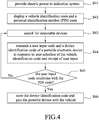
- the pairing procedure is implemented for pairing the portable electronic device 3 and the vehicle 1 before a wireless connection therebetween is established. ReferringtoFIG. 4, the pairing procedure for pairing the portable electronic device 3 and the vehicle 1 is described first.
Landscapes
- Engineering & Computer Science (AREA)
- Physics & Mathematics (AREA)
- General Physics & Mathematics (AREA)
- Computer Networks & Wireless Communication (AREA)
- Mechanical Engineering (AREA)
- Transportation (AREA)
- Signal Processing (AREA)
- Lock And Its Accessories (AREA)
- Traffic Control Systems (AREA)
- Lighting Device Outwards From Vehicle And Optical Signal (AREA)
- Electric Propulsion And Braking For Vehicles (AREA)
- Fittings On The Vehicle Exterior For Carrying Loads, And Devices For Holding Or Mounting Articles (AREA)
Abstract
Description
- The disclosure relates to a method and an indicating system for a vehicle.
- A user of a vehicle usually parks the vehicle in a parking lot of a shopping mall or a wholesale store when going shopping. However, it is troublesome for the user to locate the parked vehicle when the parking lot is relatively large. Further, the user may even forget where the vehicle is parked.
- Therefore, an object of the present disclosure is to provide a method and an indicating system for a vehicle.
- According to one aspect of the present disclosure, a method is to be implemented by a vehicle capable of communicating with a portable electronic device. The vehicle includes an electrical system that includes a power switch, and an indicating system that includes a processor, a wireless transmission module and an indicating unit.
- The method includes steps of: controlling, by the processor, the electrical system to temporarily provide electric power to the indicating system after the power switch is switched from a conductive state to a non-conductive state; determining, by the processor, whether a wireless connection is established between the portable electronic device and the wireless transmission module; and when it is determined by the processor that the wireless connection is established, activating, by the processor, the indicating unit to output an indication signal.
- According to another aspect of the present disclosure, a method for a vehicle capable of communicating with a portable electronic device is provided. The vehicle includes an electrical system that includes a power switch, and an indicating system that includes a processor, a wireless transmission module and an indicating unit.
- The method includes steps of: controlling, by the processor, the electrical system to temporarily provide electric power to the indicating system after the power switch is switched from a conductive state to a non-conductive state; determining, by the processor, whether a wireless signal from the portable electronic device is received through the wireless transmission module; and when it is determined by the processor that the wireless signal is received, activating, by the processor, the indicating unit to output an indication signal.
- According to still another aspect of the present disclosure, a method for a vehicle capable of communicating with a portable electronic device is provided. The vehicle includes an electrical system that includes a power switch, and an indicating system that includes a processor, a wireless transmission module and an indicating unit.
- The method includes steps of: controlling, by the processor, the electrical system to provide electric power to the indicating system when the power switch is in a conductive state; determining, by the processor, whether one of a first condition that a wireless connection is established between the portable electronic device and the wireless transmission module and a second condition that a wireless signal from the portable electronic device is received through the wireless transmission module is satisfied; and when it is determined by the processor that one of the first and second conditions is satisfied, activating, by the processor, the indicating unit to output an indication signal.
- According to yet another aspect of the present disclosure, an indicating system to be installed on a vehicle for the vehicle is provided. The vehicle includes an electrical system that includes a power switch. The indicating system includes a host computer and an indicating unit. The host computer includes a processor, and a wireless transmission module electrically connected to the processor and operable to establish a wireless connection with a portable electronic device and to receive a wireless signal from the portable electronic device. The indicating unit is electrically connected to the host computer. When the processor controls the electrical system to provide electric power to the indicating system, the processor activates the indicating unit to output an indication signal when the processor determines that one of a first condition that a wireless connection is established between the portable electronic device and the wireless transmission module and a second condition that a wireless signal from the portable electronic device is received through the wireless transmission module is satisfied.
- Other features and advantages of the present disclosure will become apparent in the following detailed description of the embodiments with reference to the accompanying drawings, of which:
-
FIG. 1 is a fragmentary schematic perspective view of a vehicle provided with an indicating system for the vehicle according to an embodiment of the present disclosure; -
FIG. 2 is a schematic perspective view illustrating a power switch of the vehicle being operated between a conductive state and a non-conductive state; -
FIG. 3 is a block diagram of the vehicle and a block diagram of a portable electronic device communicating with the vehicle; -
FIG. 4 is a flow chart illustrating a pairing procedure of a method for the vehicle according to an embodiment of the present disclosure; -
FIG. 5A is a flow chart illustrating one example of an indicating procedure of the method for the vehicle; -
FIG. 5B is a flow chart illustrating another example of the indicating procedure of the method for the vehicle; -
FIG. 6 is a schematic view illustrating a display of the vehicle generating breathing light; and -
FIG. 7 is a flow chart illustrating yet another example of the indicating procedure of the method for the vehicle. - Referring to
FIGS. 1 to 3 , avehicle 1 is installed with an indicatingsystem 2 for thevehicle 1 according to an embodiment of this disclosure, and is capable of communicating with a portableelectronic device 3. Thevehicle 1 can be an automobile, a scooter, an all terrain vehicle (ATV), a utility vehicle (UV), an electric vehicle, or any transportation carrier. In this embodiment, thevehicle 1 is a scooter but the disclosure is not limited in this aspect. Thevehicle 1 includes amain body 10, and anelectrical system 9 electrically connected to the indicatingsystem 2. Theelectrical system 9 includes apower switch 91 having akey hole 910 that is paired with a key 911, and abattery 92. As shown inFIG. 2 , thepower switch 91 can be switched between a conductive state (ON) and a non-conductive state (OFF) by inserting the key 911 into thekey hole 910 and rotating the key 911 in a clockwise direction to an "ON" position (see the upper part ofFIG. 2 ) and in a counter-clockwise direction to an "OFF" position (see the lower part ofFIG. 2 ), respectively. In this embodiment, thepower switch 91 is a main switch of thevehicle 1. - Generally, the
battery 92 provides electric power to thevehicle 1 when thepower switch 91 is switched to the conductive state, and stops providing electric power to most components of thevehicle 1 when thepower switch 91 is switched to the non-conductive state (will be explained later). Note that, in other embodiments, the combination of the key 911 and thepower switch 91 may be implemented by a smart key and a keyless switch, and the present disclosure is not limited in this respect. - The indicating
system 2 is mounted to themain body 10, and includes ahost computer 21 and an indicatingunit 22. Thehost computer 21 includes aprocessor 211, awireless transmission module 212 electrically connected to theprocessor 211, and astorage module 213 electrically connected to theprocessor 211. Thewireless transmission module 212 is implemented by a Bluetooth transmission module in this embodiment. In other embodiments, thewireless transmission module 212 may be implemented as a Wi-Fi module, a near field communication module, etc. The indicatingunit 22 is electrically connected to theprocessor 211 of thehost computer 21, and is activated by theprocessor 211 to output an indication signal so as to indicate a position of thevehicle 1 to a user of the portableelectronic device 3. - The indicating
unit 22 includes adisplay 220 to be dimmed and brightened at a cycle simulating a breathing rhythm, which is referred to as generating breathing light hereinafter, aturn signal 222 to generate flashing light, ahorn 223 to output sound, and adecorative light device 224 to emit decorative light. Thedisplay 220, theturn signal 222, thespeaker 223 and thedecorative light device 224 may individually or cooperatively indicate the position of thevehicle 1. In other words, one or more of the breathing light generated by thedisplay 220, the flashing light generated by theturn signal 22, the sound outputted by thehorn 223 and the decorative light generated by thedecorative light device 224 may serve as the indicating signal. In some embodiments, the indicatingunit 22 may include one or more of thedisplay 220, theturn signal 222, thehorn 223 and thedecorative light 224. - The portable
electronic device 3 includes aprocessing unit 31, astorage unit 32, awireless transmission unit 33, adisplay 34 and aninput unit 35. Thestorage unit 32 stores an application program (APP) 321 therein, and is implemented by a hard disk in this embodiment. Thewireless transmission unit 33 is configured to wirelessly communicate with thewireless transmission module 212 of thehost computer 21 of the indicatingsystem 2, and thus has to use the same communication protocol as thewireless transmission module 212. That is to say, thewireless transmission unit 33 of the portableelectronic device 3 is also implemented by a Bluetooth transmission module in this embodiment, and can be implemented by any transmission module using any other wireless transmission technology as long as the same communication protocol is used by thewireless transmission unit 33 and thewireless transmission module 212. In this embodiment, thedisplay 34 and theinput unit 35 of the portableelectronic device 3 are integrated as a touch screen, but the disclosure is not limited in this respect. - Referring to
FIGS. 4 ,5A and5B , a method for indicating a position of thevehicle 1 according to some embodiments of this disclosure is shown to include a pairing procedure (FIG. 4 ) and an indicating procedure (FIGS. 5A and5B ). The pairing procedure is implemented for pairing the portableelectronic device 3 and thevehicle 1 before a wireless connection therebetween is established. ReferringtoFIG. 4, the pairing procedure for pairing the portableelectronic device 3 and thevehicle 1 is described first. - In step S41, the
processor 21 controls theelectrical system 9 to provide electric power from thebattery 92 to the indicatingsystem 2 when thepower switch 91 is in the conductive state. - In step S42, the
display 220 of the indicatingunit 22 of the indicatingsystem 2 is activated by the user, e.g., pressing a button (not shown) on thevehicle 1, to display a vehicle identification code of thevehicle 1 and a personal identification number (PIN) code, and thewireless transmission module 212 sends out the vehicle identification code. In this embodiment, thewireless transmission module 212 and thewireless transmission unit 33 are both Bluetooth transmission modules, and the vehicle identification code is a media access control (MAC) address of thevehicle 1. Note that in other embodiments where thewireless transmission module 212 and thewireless transmission unit 33 are implemented using other wireless transmission technologies, the vehicle identification code of thevehicle 1 may be international mobile equipment identity (IMEI), and the present disclosure is not limited in this respect. In some embodiments, the vehicle identification code is randomly generated. In some embodiments, thedisplay 220 of the indicatingunit 22 only displays the vehicle identification code in this step. - In step S43, the APP 321 stored in the
storage unit 32 is activated by the user to search for detectable devices including thevehicle 1, which is to be paired therewith, and then thedisplay 34 of the portableelectronic device 3 displays the vehicle identification code of thevehicle 1 when the vehicle identification code is searched out. Then, the portableelectronic device 3 allows the user to input a user input code and to select the vehicle identification code. The user is expected to look at thedisplay 220 which has the PIN code displayed thereon, and enter the corresponding digits as the user input code for authentication purpose. For example, theprocessing unit 31 executes the APP 321 to make thedisplay 34 display an interface allowing the user to input the user input code and to select the vehicle identification code via theinput unit 35. In some embodiments, thedisplay 34 of the portableelectronic device 3 displays a vehicle model of thevehicle 1, rather than the vehicle identification code, for the user selection. - In step S44, in response to the user selection of the vehicle identification code and the user input of the user input code, the portable
electronic device 3 transmits the user input code and a device identification code of the portableelectronic device 3 to thewireless transmission module 212 of the indicatingunit 21. - In step S45, the
processor 211 determines whether the user input code received from the portableelectronic device 3 through thewireless transmission module 212 conforms with the PIN code. When the determination made in step S45 is affirmative, the flow goes to step S46; otherwise, the flow goes back to step S43. - In step S46, the
processor 211 stores the device identification code of the portableelectronic device 3 in thestorage module 213 and pairs the portableelectronic device 3 with thevehicle 1. - Note that in some embodiments of this disclosure, the
display 220 of the indicatingsystem 2 may display only the vehicle identification code of thevehicle 1 in step S42. In this case, thedisplay 34 only displays the vehicle identification code and the portableelectronic device 3 allows the user to select the vehicle identification code displayed on thedisplay 34 in step S43. Then, the portableelectronic device 3 only transmits the device identification code of the portableelectronic device 3 to thewireless transmission module 212 of the indicatingunit 21 in step S44, and thus, theprocessor 211 directly stores the device identification code in thestorage module 213 and pairs the portableelectronic device 3 with thevehicle 1 without implementing step S45. - Now turning to
FIG. 5A , one example of the indicating procedure of the method for indicating a position of thevehicle 1 is illustrated. In step S51, theprocessor 211 controls theelectrical system 9 to temporarily provide electric power from thebattery 92 to the indicatingsystem 2 after thepower switch 91 is switched from the conductive state to the non-conductive state, such that the indicatingsystem 2 operates in a standby state. In the standby state, thewireless transmission module 212 is powered up by the electric power provided by thebattery 92 to detect a radio signal in compliance with the transmission protocol used by thewireless transmission module 212, i.e., Bluetooth in this embodiment. In this embodiment, theprocessor 211 controls thebattery 92 to provide electric power to the indicatingsystem 2 for a predetermined duration (e.g., 48 hours) after thepower switch 91 is switched from the conductive state to the non-conductive state. When the predetermined duration has elapsed, theelectrical system 9 stops outputting electric power to the indicatingsystem 2 and the method is terminated. - In step S52, the
processor 211 determines whether a wireless connection is established between thewireless transmission unit 33 of the portableelectronic device 3 and thewireless transmission module 212 of the indicatingsystem 21. When it is determined by theprocessor 211 that a wireless connection is established, the flowgoes to step S53; otherwise, step S52 is repeated. Generally, since the portableelectronic device 3 has been paired with thevehicle 1 in advance (after completion of the pairing procedure), the wireless connection between thewireless transmission unit 33 of the portableelectronic device 3 and thewireless transmission module 212 of the indicatingsystem 21 should be automatically established once a radio signal transmitted by thewireless transmission unit 33 of the portableelectronic device 3 is detected by thewireless transmission module 212 of the indicatingsystem 21. In this case, "pairing a device with another device" means that the two devices are bonded and the next time the two devices come into vicinity of each other, an automatic wireless connection will be established without requiring further user operation. - In step S53, the
processor 211 activates the indicatingunit 22 to output the indication signal so as to indicate a position of thevehicle 1 to the user of the portableelectronic device 3. In some embodiments, theprocessor 211 controls the indicatingunit 22 to repeatedly output the indication signal at a frequency that is directly proportional to a strength of the wireless connection (i.e., a strength of a wireless signal received from the portableelectronic device 3 through the wireless transmission module 212) . - Further referring to
FIG. 5B , another example of the indicating procedure of the method is illustrated. In this example, steps S51' and S53' are identical to steps S51 and S53 ofFIG. 5A , and descriptions thereof are thus omitted for the sake of brevity. The difference between the foregoing example illustrated inFIG. 5A and this example resides in the following. In step S52', thewireless transmission module 212 is powered up to detect whether the portableelectronic device 3 is in proximity of thevehicle 1 by determining whether a wireless signal from thewireless transmission unit 33 of the portableelectronic device 3 is received. When the determination made above is affirmative, a flow goes to step S53' ; otherwise, step S52' is repeated. In this embodiment, theprocessor 211 activates the indicatingunit 22 to output the indication signal once the wireless signal from thewireless transmission unit 33 of the portableelectronic device 3 is received by thewireless transmission unit 212 without establishing a wireless connection between thewireless transmission unit 33 and thewireless transmission module 212. In this case, "pairing a device with another device" means that the next time the two devices come into vicinity of each other, one device can identify the other device without requiring further user operation. - An example of using the embodiments of the present disclosure will be described in the following. When a user of the
vehicle 1, which is parked in a wholesale parking lot, finishes shopping and returns to the wholesale parking lot with the portableelectronic device 3, which is paired with thevehicle 1 in advance, the indicatingunit 22 will be activated by theprocessor 211 when a strength of a wireless signal received from the portableelectronic device 3 through thewireless transmission module 212 is larger than a predetermined received signal strength (RSS) value (e.g., -80 dB). As a result of the activation, the indicatingunit 22 outputs an indication signal such as sound and/or light to indicate the position of thevehicle 1 to the user. As shown inFIG. 6 , thedisplay 220 of the indicating unit 22 (seeFIG. 2 ) generates the breathing light as the indication signal when the wireless signal from the portableelectronic device 3 is received and the strength thereof is larger than the predetermined RSS value. Specifically, in this example, thedisplay 220 of the indicatingunit 22 is controlled to repeatedly generate the breathing light with a predetermined luminance and color, e.g., red, at a breathing frequency (i.e., the frequency of the light being cyclically dimmed and brightened) that is directly proportional to the strength of the received wireless signal. That is to say, as the user approaches thevehicle 1, the breathing frequency of the breathing light generated by thedisplay 220 increases. - In other examples, the color of the light generated by the
display 220 of the indicatingunit 22 may vary according to the strength of the wireless signal. For example, thedisplay 220 generates red light as the indication signal when the strength of the wireless signal is relatively weak as the user is relatively far away from thevehicle 1, and generates green light as the indication signal when the strength of the wireless signal is relatively strong as the user is relatively close to thevehicle 1. In yet another example, theturn signal 222, thehorn 223 and the decorativelight device 224 of the indicatingunit 22 maybe successively turned on to generate the flashing light, to output the sound and to emit the decorative light as the user approaches thevehicle 1. Additionally, the sound and/or light generated by the indicatingunit 22 can be customized by using the APP 321 as required. By this way, the indicatingunit 22 provides a splendid visual aesthetic effect to thevehicle 1. - Referring to
FIG. 7 , yet another example of the indicating procedure of the method for indicating the position of thevehicle 1 is illustrated. In step S71, theprocessor 211 controls theelectrical system 9 to provide electric power from thebattery 92 to the indicatingsystem 2 after thepower switch 91 is switched from the non-conductive state to the conductive state. In step S72, theprocessor 211 determines whether a wireless signal from the portableelectronic device 3 is received or whether a wireless connection is established between thewireless transmission unit 33 and thewireless transmission module 212. When either one of the determinations made above is affirmative, the flow of the method goes to step S73; otherwise, step S72 is repeated. In step S73, theprocessor 211 activates the indicatingunit 22 to output an indication signal to indicate a position of thevehicle 1 to the user of the portableelectronic device 3. - In a scenario that the
vehicle 1 has been stolen, once the user/owner of thevehicle 1 carrying the portableelectronic device 3 approaches thevehicle 1 to the extent that a strength of the wireless signal received by thewireless transmission unit 33 is larger than the predetermined RSS value or the wireless connection is established between thewireless transmission unit 33 and thewireless transmission module 212, the indicatingunit 22 is activated to output the indication signal to thereby notify the user of a position of thevehicle 1. - To sum up, in the present disclosure, by virtue of the
wireless transmission module 212 that is temporarily provided with electric power as controlled by theprocessor 211, the indicatingunit 22 is activated to output an indication signal when either a wireless signal from the portableelectronic device 3 is received or a wireless connection is established between the portableelectronic device 3 and thevehicle 1, such that the indicatingunit 22 can provide the splendid visual aesthetic effect to thevehicle 1 when the user approaches thevehicle 1. In addition, the user of thevehicle 1 can be notified of a position of thevehicle 1 by the indicating signal regardless of whether thepower switch 91 of thevehicle 1 is in the conductive state or in the non-conductive state (within the predetermined duration). - In the description above, for the purposes of explanation, numerous specific details have been set forth in order to provide a thorough understanding of the embodiment. It will be apparent, however, to one skilled in the art, that one or more other embodiments may be practiced without some of these specific details. It should also be appreciated that reference throughout this specification to "one embodiment," "an embodiment," an embodiment with an indication of an ordinal number and so forth means that a particular feature, structure, or characteristic may be included in the practice of the disclosure. It should be further appreciated that in the description, various features are sometimes grouped together in a single embodiment, figure, or description thereof for the purpose of streamlining the disclosure and aiding in the understanding of various inventive aspects.
Claims (15)
- A method for a vehicle (1), the method to be implemented by a vehicle (1) capable of communication with a portable electronic device (3), the vehicle (1) including an electrical system (9) that includes a power switch (91), and an indicating system (2) that includes a processor (211), a wireless transmission module (212) and an indicating unit (22), the method characterized by steps of:controlling, by the processor (211), the electrical system (9) to temporarily provide electric power to the indicating system (2) after the power switch (91) is switched from a conductive state to a non-conductive state;determining, by the processor (211), whether a wireless connection is established between the portable electronic device (3) and the wireless transmission module (212);when it is determined by the processor (211) that the wireless connection is established, activating, by the processor (211), the indicating unit (22) to output an indication signal.
- The method as claimed in Claim 1, characterized in that the step of activating the indicating unit (22) to output an indication signal includes controlling the indicating unit (22) to repeatedly output the indication signal at a frequency that is directly proportional to a strength of the wireless connection.
- The method as claimed in Claim 1, the indicating unit (22) including a display (220), the indicating system (2) further including a storage module (213), the method further characterized in that a pairing procedure including steps of:displaying, by the display (220), a vehicle identification code of the vehicle (1) when the power switch (91) is in a conductive state;sending out, by the wireless transmission module (212), the vehicle identification code to be searched by the portable electronic device (3) and displayed thereon, after which the portable electronic device (3) allows a user to select the vehicle identification code, and transmits a device identification code of the portable electronic device (3) to the wireless transmission module (212) in response to user selection of the vehicle identification code;receiving, by the wireless transmission module (212), the device identification code from the portable electronic device (3); andstoring, by the processor (211), the device identification code of the portable electronic device (3) in the storage module (213) and pairing the portable electronic device (3) with the vehicle (1) to allow the wireless connection to be established therebetween.
- A method for a vehicle, the method to be implemented by a vehicle (1) capable of communication with a portable electronic device (3), the vehicle (1) including an electrical system (9) that includes a power switch (91), and an indication system (2) that includes a processor (211), a wireless transmission module (212), and an indicating unit (22), the method characterized by steps of:controlling, by the processor (211), the electrical system (9) to temporarily provide electric power to the indicating system (2) after the power switch (91) is switched from a conductive state to a non-conductive state;determining, by the processor (211), whether a wireless signal from the portable electronic device (3) is received through the wireless transmission module (212) ;when it is determined by the processor (211) that the wireless signal is received, activating, by the processor (211), the indicating unit (22) to output an indication signal.
- The method as claimed in Claim 4, characterized in that the step of activating the indicating unit (22) to output an indication signal includes controlling the indicating unit (22) to repeatedly output the indication signal at a frequency that is directly proportional to a strength of the wireless signal received from the portable electronic device (3).
- The method as claimed in Claim 4, the indicating unit (22) including a display (220), the indicating system (2) further including a storage module (213), the method further characterized by a pairing procedure including steps of:displaying, by the display (220), a vehicle identification code of the vehicle (1) when the power switch (91) is in a conductive state;sending out, by the wireless transmission module (212), the vehicle identification code, the portable electronic device (3) allowing a user select the vehicle identification code after searching out and displaying the vehicle identification code, the portable electronic device (3) transmitting a device identification code of the portable electronic device (3) to the wireless transmission module (212) inresponse to user selection of the vehicle identification code;receiving, by the wireless transmission module (212), the device identification code from the portable electronic device (3); andstoring, by the processor (211), the device identification code of the portable electronic device (3) in the storage module (213) and pairing the portable electronic device (3) with the vehicle (1) to allow transmission of the wireless signal.
- A method for a vehicle, the method to be implemented by a vehicle (1) capable of communication with a portable electronic device (3), the vehicle (1) including an electrical system (9) that includes a power switch (91), and an indicating system (2) that includes a processor (211), a wireless transmission module (212) and an indicating unit (22), the method characterized by steps of:controlling, by the processor (211), the electrical system (9) to provide electric power to the indicating system (2) when the power switch (91) is in a conductive state;determining, by the processor (211), whether one of a first condition that a wireless connection is established between the portable electronic device (3) and the wireless transmission module (212) and a second condition that a wireless signal from the portable electronic device (3) is received through the wireless transmission module (212) is satisfied;when it is determined by the processor (211) that one of the first and second conditions is satisfied, activating, by the processor (211), the indicating unit (22) to output an indication signal.
- The method as claimed in Claim 7, characterized in that the step of activating the indicating unit (22) to output an indication signal includes controlling the indicating unit (22) to repeatedly output the indication signal at a frequency that is directly proportional to a strength of the wireless connection in the first condition or a strength of the wireless signal received from the portable electronic device (3) in the second condition.
- The method as claimed in Claim 7, the indicating unit (22) including a display (220), the indicating system (2) further including a storage module (213), the method further characterized by a pairing procedure including steps of:displaying, by the display (220), a vehicle identification code of the vehicle (1) when the power switch (91) is in a conductive state;sending out, by the wireless transmission module (212), the vehicle identification code, the portable electronic device (3) allowing a user to select the vehicle identification code after searching out and displaying the vehicle identification code, the portable electronic device (3) transmitting a device identification code of the portable electronic device (3) to the wireless transmission module (212) inresponse to user selection of the vehicle identification code;receiving, by the wireless transmission module (212), the device identification code from the portable electronic device (3); andstoring, by the processor (211), the device identification code of the portable electronic device (3) in the storage module (213) and pairing the portable electronic device (3) with the vehicle (1).
- An indicating system (2) to be installed on a vehicle (1), the vehicle (1) including an electrical system (9) that includes a power switch (91), said indicating system (2) characterized by:a host computer (21) that includes a processor (211), and a wireless transmission module (212) electrically connected to said processor (211) and being operable to establish a wireless connection with a portable electronic device (3) and to receive a wireless signal from the portable electronic device (3); andan indicating unit (22) electrically connected to said host computer (21),wherein, when said processor (211) controls the electrical system (9) to temporarily provide electric power to said indicating system (2) after the power switch (91) is switched from a conductive state to a non-conductive state, said processor (211) activates said indicating unit (22) to output an indication signal when said processor (211) determines that one of a first condition that a wireless connection is established between the portable electronic device (3) and said wireless transmission module (212) and a second condition that a wireless signal from the portable electronic device (3) is received through said wireless transmission module (212) is satisfied; andwherein, when said processor (211) controls the electrical system (9) to provide electric power to said indicating system (2) after the power switch (91) is switched from the non-conductive state to the conductive state, said processor (211) activates said indicating unit (22) to output the indication signal when said processor (211) determines that one of the first condition and the second condition is satisfied.
- The indicating system as claimed in Claim 10, characterized in that said indicating unit (22) is activated by said processor (211) to repeatedly output the indication signal at a frequency that is directly proportional to a strength of the wireless connection in the first condition or a strength of the wireless signal received from the portable electronic device (3) in the second condition.
- The indicating system as claimed in Claim 10, characterized in that said host computer (21) further includes a storage module (213) electrically connected to said processor (211), and said indicating unit (22) includes a display (220),
wherein, when said indicating system (2) implements in a pairing procedure,said display (220) displays a vehicle identification code of the vehicle (1) while the power switch (91) is in a conductive state,said wireless transmission module (212) sends out the vehicle identification code, the portable electronic device (3) allowing a user to select the vehicle identification code after searching out and displaying the vehicle identification code, the portable electronic device (3) transmitting a device identification code of the portable electronic device (3) to said wireless transmission module (212) in response to user selection of the vehicle identification code, andsaid processor (211) stores the device identification code of the portable electronic device (3) in said storage module (213) and pairs the portable electronic device (3) with the vehicle (1) to allow the wireless connection to be established or the wireless signal to be received. - The indicating system as claimed in Claim 10, characterized in that said wireless transmission module (212) is a Bluetooth transmission module.
- The indicating system as claimed in Claim 10, characterized in that said indicating unit (22) includes at least one of a display (220) to generate breathing light as the indication signal, a turn signal (222) to generate flashing light as the indication signal, a horn (223) to output sound as the indication signal, and a decorative light device (224) to emit decorative light as the indication signal.
- The indicating system as claimed in Claim 10, characterized in that said power switch (91) is a main switch of the vehicle (1).
Applications Claiming Priority (1)
| Application Number | Priority Date | Filing Date | Title |
|---|---|---|---|
| TW105133152A TWI629188B (en) | 2016-10-14 | 2016-10-14 | Vehicle prompting method and vehicle prompting system |
Publications (1)
| Publication Number | Publication Date |
|---|---|
| EP3309764A1 true EP3309764A1 (en) | 2018-04-18 |
Family
ID=60119830
Family Applications (1)
| Application Number | Title | Priority Date | Filing Date |
|---|---|---|---|
| EP17195573.5A Ceased EP3309764A1 (en) | 2016-10-14 | 2017-10-10 | Method and indicating system for a vehicle |
Country Status (5)
| Country | Link |
|---|---|
| US (1) | US10123401B2 (en) |
| EP (1) | EP3309764A1 (en) |
| JP (1) | JP6483777B2 (en) |
| PH (1) | PH12017000287A1 (en) |
| TW (1) | TWI629188B (en) |
Cited By (1)
| Publication number | Priority date | Publication date | Assignee | Title |
|---|---|---|---|---|
| EP3922518A4 (en) * | 2019-03-12 | 2022-11-23 | Hyundai Doosan Infracore Co., Ltd. | CONSTRUCTION EQUIPMENT CONTROL SYSTEM AND CONSTRUCTION EQUIPMENT CONTROL METHOD |
Families Citing this family (4)
| Publication number | Priority date | Publication date | Assignee | Title |
|---|---|---|---|---|
| US11714153B2 (en) | 2019-05-29 | 2023-08-01 | Nvision Solutions, Inc. | Remote controlled navigation/locator beacon system |
| US11329894B2 (en) * | 2020-05-05 | 2022-05-10 | At&T Intellectual Property I, L.P. | Frame-based network condition indicator for user equipment including for 5G or other next generation user equipment |
| KR20230064827A (en) * | 2021-11-04 | 2023-05-11 | 현대자동차주식회사 | vehicle, CONTROL METHOD THEREOF AND ANTENNA DEVICE |
| EP4511828A1 (en) * | 2022-04-20 | 2025-02-26 | RTB GmbH & Co. KG | Localisation system for small electric vehicles |
Citations (3)
| Publication number | Priority date | Publication date | Assignee | Title |
|---|---|---|---|---|
| US20090115639A1 (en) * | 2007-11-05 | 2009-05-07 | Gm Global Technology Operations, Inc. | Method and system for indicating a location of a vehicle |
| US20160063786A1 (en) * | 2014-08-26 | 2016-03-03 | Hyundai America Technical Center, Inc. | Smartphone enabled passive entry go system |
| US20160293008A1 (en) * | 2015-03-30 | 2016-10-06 | Toyota Motor Engineering & Manufacturing North America, Inc. | Proximity-based vehicle location alerts |
Family Cites Families (12)
| Publication number | Priority date | Publication date | Assignee | Title |
|---|---|---|---|---|
| JP4159735B2 (en) * | 2000-10-16 | 2008-10-01 | 三菱電線工業株式会社 | Control device for automotive outdoor lights |
| US7171331B2 (en) * | 2001-12-17 | 2007-01-30 | Phatrat Technology, Llc | Shoes employing monitoring devices, and associated methods |
| US8620480B2 (en) * | 2003-04-25 | 2013-12-31 | George Alexanian | Irrigation water conservation with automated water budgeting and time of use technology |
| JP2005161904A (en) * | 2003-11-28 | 2005-06-23 | Alpha Corp | Direction indicator |
| TWI273782B (en) * | 2005-07-25 | 2007-02-11 | Sin Etke Technology Co Ltd | Short-distance wireless transmission system of electric device in vehicle |
| US20090256483A1 (en) * | 2006-06-08 | 2009-10-15 | Lutron Electronics Co., Inc. | Load Control Device Having a Visual Indication of an Energy Savings Mode |
| US8326136B1 (en) * | 2009-02-12 | 2012-12-04 | Lab Partners Associates, Inc. | Systems and methods for communicating with a device using one or more camera body controls |
| US20110082599A1 (en) * | 2009-10-06 | 2011-04-07 | Makarand Shinde | Optimizing Utility Usage by Smart Monitoring |
| US9096128B2 (en) * | 2013-01-14 | 2015-08-04 | Intel Corporation | Creating a sensory experience in a vehicle |
| US9327645B2 (en) * | 2013-08-28 | 2016-05-03 | Harman International Industries, Incorporated | Providing alerts for objects left in a vehicle |
| TWI564181B (en) * | 2014-08-19 | 2017-01-01 | 坦億有限公司 | Replaceable dashboard module, dashboard integration system, and display method |
| CN105261225A (en) * | 2015-09-30 | 2016-01-20 | 肖建辉 | Monitoring system for improving driving behavioral habits |
-
2016
- 2016-10-14 TW TW105133152A patent/TWI629188B/en active
-
2017
- 2017-10-06 US US15/726,949 patent/US10123401B2/en active Active
- 2017-10-06 PH PH12017000287A patent/PH12017000287A1/en unknown
- 2017-10-10 EP EP17195573.5A patent/EP3309764A1/en not_active Ceased
- 2017-10-11 JP JP2017197452A patent/JP6483777B2/en active Active
Patent Citations (3)
| Publication number | Priority date | Publication date | Assignee | Title |
|---|---|---|---|---|
| US20090115639A1 (en) * | 2007-11-05 | 2009-05-07 | Gm Global Technology Operations, Inc. | Method and system for indicating a location of a vehicle |
| US20160063786A1 (en) * | 2014-08-26 | 2016-03-03 | Hyundai America Technical Center, Inc. | Smartphone enabled passive entry go system |
| US20160293008A1 (en) * | 2015-03-30 | 2016-10-06 | Toyota Motor Engineering & Manufacturing North America, Inc. | Proximity-based vehicle location alerts |
Cited By (2)
| Publication number | Priority date | Publication date | Assignee | Title |
|---|---|---|---|---|
| EP3922518A4 (en) * | 2019-03-12 | 2022-11-23 | Hyundai Doosan Infracore Co., Ltd. | CONSTRUCTION EQUIPMENT CONTROL SYSTEM AND CONSTRUCTION EQUIPMENT CONTROL METHOD |
| US12074977B2 (en) | 2019-03-12 | 2024-08-27 | Hd Hyundai Infracore Co., Ltd. | Construction machine control system and construction machine control |
Also Published As
| Publication number | Publication date |
|---|---|
| JP6483777B2 (en) | 2019-03-13 |
| PH12017000287B1 (en) | 2018-07-30 |
| JP2018062337A (en) | 2018-04-19 |
| PH12017000287A1 (en) | 2018-07-30 |
| US10123401B2 (en) | 2018-11-06 |
| TW201813842A (en) | 2018-04-16 |
| TWI629188B (en) | 2018-07-11 |
| US20180110113A1 (en) | 2018-04-19 |
Similar Documents
| Publication | Publication Date | Title |
|---|---|---|
| US10123401B2 (en) | Method and indicating system for a vehicle | |
| US10000164B2 (en) | Vehicle camera peripheral | |
| KR102469565B1 (en) | Car control method of electronic apparatus and electronic appparatus thereof | |
| EP2862122B1 (en) | System and method for finding an object at distance | |
| US20160078765A1 (en) | Device, system and method for finding a parked vehicle | |
| US10096188B2 (en) | Fixed location based trainable transceiver for the control of remote devices systems and methods | |
| WO2014159873A1 (en) | Proximity tag for vehicles | |
| KR101880715B1 (en) | Method and apparatus for notifying bus passengers | |
| CN107054246A (en) | The personal device user interface and notice of extension | |
| US20110175722A1 (en) | Wireless device inventory scanner | |
| US20130135095A1 (en) | Device Locator | |
| EP3290317A1 (en) | Wireless connection system between a smartphone and an e-bike | |
| KR102267008B1 (en) | Case of portable terminal and method for controlling smart key of portable terminal | |
| US9740244B2 (en) | Color changing cover | |
| JP2006120046A (en) | In-vehicle information providing apparatus and information providing method | |
| KR20160029605A (en) | Parking Locator App smart device using Beacon. | |
| KR20190104317A (en) | Back cover for mobile terminal with remote control function and control method of electronic products using same | |
| CN113179483A (en) | Vehicle key, method for reminding by means of vehicle key and program product | |
| JP2014164745A (en) | Reader-writer device | |
| KR102496581B1 (en) | Electronic apparatus for supporting quick discovery of belonging, and control method of electronic apparatus | |
| CN117173927A (en) | Intelligent car finding method, device, equipment and storage medium | |
| KR20230135362A (en) | Loss prevention system for valuable for vehicle | |
| WO2016148051A1 (en) | Portable machine and vehicle communication system | |
| CN106097675A (en) | Tracer | |
| JPH0675031A (en) | Direction detecting system |
Legal Events
| Date | Code | Title | Description |
|---|---|---|---|
| PUAI | Public reference made under article 153(3) epc to a published international application that has entered the european phase |
Free format text: ORIGINAL CODE: 0009012 |
|
| STAA | Information on the status of an ep patent application or granted ep patent |
Free format text: STATUS: THE APPLICATION HAS BEEN PUBLISHED |
|
| AK | Designated contracting states |
Kind code of ref document: A1 Designated state(s): AL AT BE BG CH CY CZ DE DK EE ES FI FR GB GR HR HU IE IS IT LI LT LU LV MC MK MT NL NO PL PT RO RS SE SI SK SM TR |
|
| AX | Request for extension of the european patent |
Extension state: BA ME |
|
| STAA | Information on the status of an ep patent application or granted ep patent |
Free format text: STATUS: REQUEST FOR EXAMINATION WAS MADE |
|
| 17P | Request for examination filed |
Effective date: 20181012 |
|
| RBV | Designated contracting states (corrected) |
Designated state(s): AL AT BE BG CH CY CZ DE DK EE ES FI FR GB GR HR HU IE IS IT LI LT LU LV MC MK MT NL NO PL PT RO RS SE SI SK SM TR |
|
| STAA | Information on the status of an ep patent application or granted ep patent |
Free format text: STATUS: EXAMINATION IS IN PROGRESS |
|
| 17Q | First examination report despatched |
Effective date: 20210604 |
|
| STAA | Information on the status of an ep patent application or granted ep patent |
Free format text: STATUS: THE APPLICATION HAS BEEN REFUSED |
|
| 18R | Application refused |
Effective date: 20250201 |