EP3309683A1 - Improved test manager for industrial automation controllers - Google Patents
Improved test manager for industrial automation controllers Download PDFInfo
- Publication number
- EP3309683A1 EP3309683A1 EP17150483.0A EP17150483A EP3309683A1 EP 3309683 A1 EP3309683 A1 EP 3309683A1 EP 17150483 A EP17150483 A EP 17150483A EP 3309683 A1 EP3309683 A1 EP 3309683A1
- Authority
- EP
- European Patent Office
- Prior art keywords
- test
- controller
- target
- engineering tool
- test case
- Prior art date
- Legal status (The legal status is an assumption and is not a legal conclusion. Google has not performed a legal analysis and makes no representation as to the accuracy of the status listed.)
- Granted
Links
Images




Classifications
-
- G—PHYSICS
- G06—COMPUTING OR CALCULATING; COUNTING
- G06F—ELECTRIC DIGITAL DATA PROCESSING
- G06F11/00—Error detection; Error correction; Monitoring
- G06F11/36—Prevention of errors by analysis, debugging or testing of software
- G06F11/3668—Testing of software
- G06F11/3672—Test management
- G06F11/3692—Test management for test results analysis
-
- G—PHYSICS
- G05—CONTROLLING; REGULATING
- G05B—CONTROL OR REGULATING SYSTEMS IN GENERAL; FUNCTIONAL ELEMENTS OF SUCH SYSTEMS; MONITORING OR TESTING ARRANGEMENTS FOR SUCH SYSTEMS OR ELEMENTS
- G05B23/00—Testing or monitoring of control systems or parts thereof
- G05B23/02—Electric testing or monitoring
- G05B23/0205—Electric testing or monitoring by means of a monitoring system capable of detecting and responding to faults
- G05B23/0208—Electric testing or monitoring by means of a monitoring system capable of detecting and responding to faults characterized by the configuration of the monitoring system
-
- G—PHYSICS
- G05—CONTROLLING; REGULATING
- G05B—CONTROL OR REGULATING SYSTEMS IN GENERAL; FUNCTIONAL ELEMENTS OF SUCH SYSTEMS; MONITORING OR TESTING ARRANGEMENTS FOR SUCH SYSTEMS OR ELEMENTS
- G05B19/00—Program-control systems
- G05B19/02—Program-control systems electric
- G05B19/418—Total factory control, i.e. centrally controlling a plurality of machines, e.g. direct or distributed numerical control [DNC], flexible manufacturing systems [FMS], integrated manufacturing systems [IMS] or computer integrated manufacturing [CIM]
- G05B19/41835—Total factory control, i.e. centrally controlling a plurality of machines, e.g. direct or distributed numerical control [DNC], flexible manufacturing systems [FMS], integrated manufacturing systems [IMS] or computer integrated manufacturing [CIM] characterised by program execution
-
- G—PHYSICS
- G06—COMPUTING OR CALCULATING; COUNTING
- G06F—ELECTRIC DIGITAL DATA PROCESSING
- G06F11/00—Error detection; Error correction; Monitoring
- G06F11/36—Prevention of errors by analysis, debugging or testing of software
- G06F11/3668—Testing of software
- G06F11/3672—Test management
- G06F11/3688—Test management for test execution, e.g. scheduling of test suites
-
- G—PHYSICS
- G05—CONTROLLING; REGULATING
- G05B—CONTROL OR REGULATING SYSTEMS IN GENERAL; FUNCTIONAL ELEMENTS OF SUCH SYSTEMS; MONITORING OR TESTING ARRANGEMENTS FOR SUCH SYSTEMS OR ELEMENTS
- G05B2219/00—Program-control systems
- G05B2219/20—Pc systems
- G05B2219/23—Pc programming
- G05B2219/23213—Check validity of entered data
-
- G—PHYSICS
- G05—CONTROLLING; REGULATING
- G05B—CONTROL OR REGULATING SYSTEMS IN GENERAL; FUNCTIONAL ELEMENTS OF SUCH SYSTEMS; MONITORING OR TESTING ARRANGEMENTS FOR SUCH SYSTEMS OR ELEMENTS
- G05B2219/00—Program-control systems
- G05B2219/30—Nc systems
- G05B2219/31—From computer integrated manufacturing till monitoring
- G05B2219/31343—Design of factory, manufacturing system control
-
- G—PHYSICS
- G05—CONTROLLING; REGULATING
- G05B—CONTROL OR REGULATING SYSTEMS IN GENERAL; FUNCTIONAL ELEMENTS OF SUCH SYSTEMS; MONITORING OR TESTING ARRANGEMENTS FOR SUCH SYSTEMS OR ELEMENTS
- G05B2219/00—Program-control systems
- G05B2219/30—Nc systems
- G05B2219/50—Machine tool, machine tool null till machine tool work handling
- G05B2219/50185—Monitoring, detect failures, control of efficiency of machine, tool life
-
- G—PHYSICS
- G05—CONTROLLING; REGULATING
- G05B—CONTROL OR REGULATING SYSTEMS IN GENERAL; FUNCTIONAL ELEMENTS OF SUCH SYSTEMS; MONITORING OR TESTING ARRANGEMENTS FOR SUCH SYSTEMS OR ELEMENTS
- G05B23/00—Testing or monitoring of control systems or parts thereof
- G05B23/02—Electric testing or monitoring
- G05B23/0205—Electric testing or monitoring by means of a monitoring system capable of detecting and responding to faults
- G05B23/0218—Electric testing or monitoring by means of a monitoring system capable of detecting and responding to faults characterised by the fault detection method dealing with either existing or incipient faults
- G05B23/0256—Electric testing or monitoring by means of a monitoring system capable of detecting and responding to faults characterised by the fault detection method dealing with either existing or incipient faults injecting test signals and analyzing monitored process response, e.g. injecting the test signal while interrupting the normal operation of the monitored system; superimposing the test signal onto a control signal during normal operation of the monitored system
-
- Y—GENERAL TAGGING OF NEW TECHNOLOGICAL DEVELOPMENTS; GENERAL TAGGING OF CROSS-SECTIONAL TECHNOLOGIES SPANNING OVER SEVERAL SECTIONS OF THE IPC; TECHNICAL SUBJECTS COVERED BY FORMER USPC CROSS-REFERENCE ART COLLECTIONS [XRACs] AND DIGESTS
- Y02—TECHNOLOGIES OR APPLICATIONS FOR MITIGATION OR ADAPTATION AGAINST CLIMATE CHANGE
- Y02P—CLIMATE CHANGE MITIGATION TECHNOLOGIES IN THE PRODUCTION OR PROCESSING OF GOODS
- Y02P90/00—Enabling technologies with a potential contribution to greenhouse gas [GHG] emissions mitigation
- Y02P90/02—Total factory control, e.g. smart factories, flexible manufacturing systems [FMS] or integrated manufacturing systems [IMS]
Definitions
- the logic simulator (workbench 250) shown in FIG. 2 is a software component that emulates the behavior of POUs on workstation 210.
- the purpose of the logic simulator (workbench 250) is to confirm that the logic of the controller program has been defined correctly and check that the controller program enables the controllers and field devices to function according to a design specification.
- the logic simulator (workbench 250) may read variables and other data, as needed, from work database 265 during execution of test cases.
- FIG. 7 illustrates a communication/command flow for testing of physical controllers in a manual mode.
- a user of first engineering tool 705 creates test cases and communicates, through second engineering tool 715, with physical_controller_01 725, physical_controller_02 730, and physical_controller_03 735.
- the user interacts with the physical controllers, through second engineering tool 715, to modify values in test cases using first engineering tool 710.
Landscapes
- Engineering & Computer Science (AREA)
- Theoretical Computer Science (AREA)
- Physics & Mathematics (AREA)
- General Physics & Mathematics (AREA)
- General Engineering & Computer Science (AREA)
- Quality & Reliability (AREA)
- Computer Hardware Design (AREA)
- Automation & Control Theory (AREA)
- Manufacturing & Machinery (AREA)
- Testing And Monitoring For Control Systems (AREA)
Abstract
Description
- This disclosure relates to the field of control systems including industrial or other process control systems. In particular, it relates to the testing of configurations for process controllers and the like.
- Testing the configuration of industrial controllers (also called programmable logic controllers, PLCs, programmable controllers or, simply, controllers) and field devices (sensors and actuators) in a process control system has traditionally been a manual operation. In a typical case, users manually set up test cases and procedures for a process control system and, during testing, manually select appropriate databases, and update values for the test cases to meet the requirements of a given process.
- The "background" description provided herein is for the purpose of generally presenting the context of the disclosure. Work of the presently named inventors, to the extent it is described in this background section, as well as aspects of the description which may not otherwise qualify as conventional art at the time of filing, are neither expressly nor impliedly admitted as conventional art against the present disclosure.
- An engineering tool for testing a process control system includes one or more test manager instances, wherein each test manager instance includes circuitry configured to receive at least one test case and associated test request from a source of test cases, identify a target for each test request, translate each test request into instructions to the identified target, check each test request for validity, initiate execution of each test case, monitor subscribed data generated by the target for each test case, compute a difference between the subscribed data at a first point in time and a second point in time, and generate a notification when the computed difference is greater than a first predetermined threshold.
- A more complete appreciation of the disclosure and many of the attendant advantages thereof will be readily obtained as the same becomes better understood by reference to the following detailed description when considered in connection with the accompanying drawings, wherein:
-
FIG. 1 illustrates a process control system environment that includes a process control system and development and testing facilities; -
FIG. 2 illustrates another process control system environment that includes a process control system and development and testing facilities; -
FIG. 3 illustrates yet another process control system environment that includes a process control system and development and testing facilities; -
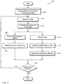
FIG. 4 illustrates a flow diagram for the testing of a process control system; -
FIG. 5 illustrates a communication/command flow for testing of a logic simulator in a manual mode; -
FIG. 6 illustrates a communication/command flow for testing of controller simulators in a manual mode; -
FIG. 7 illustrates a communication/command flow for testing of physical controllers in a manual mode; -
FIG. 8 illustrates a simplified structure of one possible configuration file; -
FIG. 9 illustrates a communication/command flow for an improved testing scenario; and -
FIG. 10 is a functional block diagram of an exemplary computing device. - When an industrial process is being developed or modified, one or more controllers must be programmed to monitor and control the various steps of the process.
- A controller may have an associated logic simulator, controller simulator and physical controller, all of which are required to be tested with a new controller program (process control program). The logic simulator is a software program that simulates the behavior of the controller program on a workstation (computer). The purpose of the logic simulator is to test that the controller program has been defined correctly and confirm that the controller program enables the controllers and field devices to function according to a design specification. The controller simulator is a program to simulate controller actions on a workstation. The purpose of the controller simulator is to test the controller program by checking if the controller functions according to a design specification in a simulated environment. Finally, the actual (physical) controller may be tested with the controller program to ensure that the controller functions according to the design specification in an actual environment, but with the controller off-line (not controlling a manufacturing process). The controller may be programmed using programming languages specified in the standard IEC 61131-3 for programmable logic controllers (PLC) or distributed control systems (DCS). The controller may be part of a DCS or a safety instrumented system (SIS).
- Referring now to the drawings, wherein like reference numerals designate identical or corresponding parts throughout the several views.
-
FIG. 1 illustrates a first processcontrol system environment 100 that includes a process control system and development and testing facilities. Processcontrol system environment 100 includes a first engineering tool 105 (which may be implemented on a PC or other computer), aworkstation 110, a control system 115 (controller simulator), one ormore controllers 120, and field devices, includingsensors 125 andactuators 130.Controller 120 controls processes through field devices within the process control system. By way of example,sensors 125 may communicate feedback to controller 120 regarding the state of one or more processes. Based on received feedback,controller 120 may generate control signals and communicate them toactuators 130 to control processes under execution. In addition,controller 120 may provide feedback (current system state, historical data, trends, etc.), and alerts (system operating outside of specified limits, failed field device or other component, etc.) to one or more operators of processcontrol system environment 100. Office/Enterprise network 135 may be used to interconnect various components of processcontrol system environment 100, includingfirst engineering tool 105 andworkstation 110. Control network 140 may be used to interconnectcontroller 120 toworkstation 110 andcontrol system 115.Field network 145 may be used to interconnect one ormore controllers 120, and field devices, includingsensors 125 andactuators 130. -
First engineering tool 105 may be employed to define, test and document the controller program forcontroller 120. When used to create test cases for testing the accuracy of the controller logic,first engineering tool 105 may be used to initiate communication withworkstation 110 for the purpose of running the test cases on a logic simulator, a controller simulator, or the actual (physical)controller 120. - Workstation 110 may include hardware and/or software that provides functionality for workbench 150 (logic simulator),
second engineering tool 155, database 160 (includingwork database 165 and master database 170), and data/symbol extractor 175. - Process
control system environment 100 provides three different but related testing environments, logic simulator (using workbench 150), controller simulator (using control system 115), and the actual (physical)controller 120. While being tested,controller 120 must be in an off-line state (not running in an active manufacturing process). - The logic simulator (workbench 150) shown in
FIG. 1 is a software component that emulates the behavior of POUs (Program Organization Units) onworkstation 110. Program Organization Units are functions, function blocks and programs that may be combined to form the controller programs. The POUs are reusable within a program and may be stored in user-declared libraries for import into other controller programs. The purpose of the logic simulator (workbench 150) is to confirm that the logic of the controller program has been defined correctly and check that the controller program enables the controllers and field devices to function according to a design specification. The logic simulator (workbench 150) may read variables and other data, as needed, fromwork database 165 during execution of test cases. Variables are values and parameters accessed by the POUs during execution of the controller programs. Default values for variables may be extracted from one of the databases and applied during testing of the controller programs. Additional values for variables may be injected during execution of test cases. -
Work database 165 is a working database which has not been compiled.Work database 165 is used by the logic simulator.Work database 165 is not downloaded to the logic simulator before use/execution of test cases. The logic simulator (in workbench 150) only reads fromwork database 165.Master database 170 is a database which has been compiled and ready to be deployed for use by the controller simulator (using control system 115) andphysical controller 120.Master database 170 must be downloaded to the controller simulator (using control system 115) or thephysical controller 120 before execution of test cases. More importantly,master database 170 has more data associated with the controller, such as network address, controller type, and communication protocols. - The controller simulator (control system 115) is a software component that simulates the actual controller actions on a computer. The purpose of the controller simulator is to test the logic of the controller program by checking if the controller functions according to design specifications in a simulated production environment. The controller simulator (control system 115) may read variables and other data, as needed, from
master database 170 during execution of test cases. -
Controller 120 allows testing of the controller program by checking that the controller functions according to design specifications in an actual production environment.Controller 120 may read variables and other data, as needed, frommaster database 170 during execution of test cases. - During actual production process control, the controller functions based on predefined control actions as well as trigger events (such as abnormal values of variables, disturbances, etc.). The test procedures, using defined test cases, may inject various scenarios and test how the controller program behaves and what output is generated by the controller program to send commands to the controller and field devices.
- An alternative scenario is illustrated in
FIG. 2 . InFIG. 2 , a processcontrol system environment 200 includes a process control system and development and testing facilities. Processcontrol system environment 200 includes afirst engineering tool 205, aworkstation 210, one ormore controllers 220, and field devices, includingsensors 225 andactuators 230. Office/Enterprise network 235 may be used to interconnect various components of the processcontrol system environment 200, includingfirst engineering tool 205 andworkstation 210.Control network 240 may be used to interconnectcontroller 220 toworkstation 210.Field network 245 may be used to interconnect one ormore controllers 220, and field devices, includingsensors 225 andactuators 230.First engineering tool 205, in processcontrol system environment 200, includescontroller emulator 280, which may function similar to the controller simulator (control system 115) inFIG.1 .Controller emulator 280 is a software component that emulates the actual controller actions onfirst engineering tool 205. The purpose of the controller emulator is to test the logic by checking if the controller functions according to design specifications in a simulated production environment. -
First engineering tool 205 may be employed to define, test and document the controller program forcontroller 220. When used to create test cases for testing the accuracy of the controller logic,first engineering tool 205 may be used to initiate communication withworkstation 210 for the purpose of running the test cases on a logic simulator, a controller emulator, or the actual (physical)controller 220. -
Workstation 210 may include hardware and/or software that provide functionality for workbench 250 (logic simulator),second engineering tool 255, and database 260 (includingwork database 265 and master database 270). - Process
control system environment 200 provides three different but related testing environments, logic simulator (using workbench 250), controller emulator (in first engineering tool 205), and the actual (physical)controller 220. While being tested,controller 220 must be in an off-line state (not running in an active manufacturing process). - As with the system illustrated in
FIG. 1 , the logic simulator (workbench 250) shown inFIG. 2 is a software component that emulates the behavior of POUs onworkstation 210. The purpose of the logic simulator (workbench 250) is to confirm that the logic of the controller program has been defined correctly and check that the controller program enables the controllers and field devices to function according to a design specification. The logic simulator (workbench 250) may read variables and other data, as needed, fromwork database 265 during execution of test cases. - The controller emulator (in first engineering tool 205) is a software component that emulates the actual controller actions on
first engineering tool 205. The purpose of the controller emulator is to test the logic of the controller program by checking if the controller functions according to design specifications in a simulated production environment. The controller emulator may read variables and other data, as needed, frommaster database 270 during execution of test cases. -
Controller 220 allows testing of the controller program by checking that the controller functions according to design specifications in an actual production environment.Controller 220 may read variables and other data, as needed, frommaster database 270 during execution of test cases. - During actual production process control, the controller functions based on predefined control actions as well as trigger events (such as abnormal values of variables, disturbances, etc.). The test procedures, using defined test cases, may inject various scenarios and test how the controller program behaves and what output is generated by the controller program to send commands to the controller and field devices.
- In the embodiments illustrated in
FIGS. 1 and2 , the logic simulator, controller simulator/emulator and physical controller are typically set up manually for testing and the testing itself is performed as a manual operation. Each of the tests is performed separately for each controller and for each of the testing targets (the logic simulator, controller simulator/emulator and physical controller). For example, as part of a specific test setup, a user may manually setup a specific simulator, choose a database (work database or master database) which is to be in communication with the testing target (possibly through a data extractor), and then manually execute the test cases for the selected simulator. -
FIG. 5 illustrates a communication/command flow for testing of a logic simulator in a manual mode. A user offirst engineering tool 505 creates test cases and communicates, throughsecond engineering tool 515, withcontroller_01 logic simulator 520. As part of the testing process, the user interacts withcontroller_01_logic simulator 520, throughsecond engineering tool 515, to modify values in test cases usingfirst engineering tool 510. -
FIG. 6 illustrates a communication/command flow for testing of controller simulators in a manual mode. Again, a user offirst engineering tool 605 creates test cases and communicates, throughsecond engineering tool 615, withcontroller_01 simulator 625,controller_02_simulator 630, andcontroller_03_simulator 635. As part of the testing process, the user interacts with the controller simulators, throughsecond engineering tool 615, to modify values in test cases usingfirst engineering tool 610. -
FIG. 7 illustrates a communication/command flow for testing of physical controllers in a manual mode. Once again, a user offirst engineering tool 705 creates test cases and communicates, throughsecond engineering tool 715, withphysical_controller_01 725,physical_controller_02 730, andphysical_controller_03 735. As part of the testing process, the user interacts with the physical controllers, throughsecond engineering tool 715, to modify values in test cases usingfirst engineering tool 710. - In addition, in the embodiments illustrated in
FIGS. 1 and2 , when the engineering tools communicate with multiple controllers, the data that is read from the controllers for monitoring the test procedure may not be displayed accurately. This diminishes the ability for users to adjust test variables for successive test cases. This reduces the efficiency and reliability of testing. - Finally, since the communication protocols for communicating with a simulator/emulator may be different from that for a physical controller, testing of a simulator/emulator and a physical controller may only be performed separately due to the different communication protocols.
- In some setups,
first engineering tool 205 includescontroller emulator 280 as inFIG. 2 .Controller emulator 280 may be tested instead ofcontroller simulator 115 as inFIG. 1 . This may be more convenient for testing since there is no need to set up an additional communication to thecontroller simulator 115, which has a different communication protocol from the physical controller. However, it is well known to a person skilled in the art that testing an emulator is less efficient. -
FIG. 9 illustrates a communication/command flow for animproved testing scenario 900. Inimproved testing scenario 900, a source of test cases 905 (which may be an engineering tool, a logic builder, or a tester) may communicate withdatabase 910 and with individualtest manager instances test manager instance interface controller - Yet another scenario is illustrated in
FIG. 3 . InFIG. 3 , processcontrol system environment 300 includes afirst engineering tool 305, aworkstation 310, a control system 315 (controller simulator), a plurality ofcontrollers sensors actuators Controllers control system environment 300. Office/Enterprise network 335 may be used to interconnect various components of processcontrol system environment 300, includingfirst engineering tool 305 andworkstation 310.Control network 340 maybe used to interconnectcontrollers workstation 310 andcontrol system 315.Field network 345 maybe used to interconnect one ormore controllers sensors actuators -
Workstation 310 may include hardware circuitry and/or software that provide functionality for workbench 350 (logic simulator),second engineering tool 355, and database 360 (includingwork databases master databases Workstation 310 may also include a non-transitory computer-readable medium storing computer-readable instructions, which may be executed byworkstation 310 to implement the features discussed herein. - Process
control system environment 300, illustrated inFIG. 3 , also includes a test manager that may include one or more test manager instances as part ofsecond engineering tool 355. The use of multiple test manager instances may improve and streamline the validation and testing process forcontrollers second engineering tool 355 may include a communication structure for data communication between the source of test cases infirst engineering tool 305 andcontrollers first engineering tool 305 into appropriate instructions to initiate a test case in the designated testing target. Additionally, each test manager instance insecond engineering tool 355 may include the capability to identify and use individual instances ofwork databases master databases second engineering tool 355 may enable the testing in an offline mode. - Each test manager instance in
second engineering tool 355 may includevalidator 390, which may be used to check testing requests fromfirst engineering tool 305 for the validity of the target device (if the target is a controller, the controller must be in an offline state to be valid) and checks the data to be written to, and read from, the target. - Each test manager instance in
second engineering tool 355 may also includemonitoring function 395, which may be used to continuously read subscribed data (data generated by the testing target during execution of the test cases).Monitoring function 395 may also compute a difference between the subscribed data at a first point in time and the subscribed data at a second point in time (N t vs. N t-1 ), and generate a notification if there is a difference. For example, if the data value of a variable N at time t is identical to the data value of N at time t-1 (Nt = N t-1 ), then no notification is generated, but if the data value of a variable N at time t is not identical to the data value of N at time t-1 (Nt ≠ Nt-1 ), then a notification is generated. In some embodiments, a notification may only be generated if the difference is greater than a predetermined threshold. In other embodiments, a notification may only be generated if a difference is greater than a predetermined threshold on more than a predetermined number of consecutive data values. In other embodiments, an alert may be generated when there is any difference between the data value at time t and t-1 (Nt ≠ N t-1 ). - In some embodiments,
monitoring function 395 andvalidator 390, may be implemented in separate processors or processor elements (cores) to enable concurrent, parallel operation in each test manager instance. This provides an important improvement over the embodiments illustrated inFIGS. 1 and2 because a user may need to view the data which is read from the target controller during execution of test cases in real time. The concurrent operation ofmonitoring function 395 andvalidator 390 is for the same controller, as each test manager instance can only communicate with one controller at a time. -
Second engineering tool 355 may also includearbiter 385, which may be used when multiple test manager instances and multiple controllers are connected for testing.Arbiter 385 may manage a queueing priority that, in some embodiments, may allow one testing target to complete a test case before starting a test case on the next target. This may improve the reliability and efficiency of testing multiple controllers. - In some embodiments of
second engineering tool 355 each test manager instance may be implemented as a separate processor or processor element, each having a dedicated communication link with one of thecontrollers controllers - In some embodiments, each test manager instance in
second engineering tool 355 receives requests based on test cases from a source (such as first engineering tool 305). A test manager instance insecond engineering tool 355 may receive test requests in the form of test commands. Configuration files may be used with the test manager to identify the information regarding the test target. The information may include target type (logic simulator, controller simulator, and physical controller), address of the target, and connection properties (communication protocol) for the target. -
FIG. 8 illustrates a simplified structure of one possible configuration file.Configuration file 805 includesaddress 810 of the target,target controller type 815, and connection properties 820 (communication protocol) for the target. -
FIG. 4 illustrates a flow diagram for atesting method 400 of a process control system. The testing flow begins atstep 405 wherein at least one test case and associated test request and, optionally, a monitoring request is received to test (and monitor) one or more controllers and affiliated logic simulators and controller simulators. Typically, at least one test case would be defined for each controller in a process control system (including the logic simulator, controller simulator, and physical controller). The logic simulator, controller simulator, and physical controller would be setup to be tested in a predefined sequence. - In
step 410 oftesting method 400, a target is identified for a test request. In some embodiments, the test manager uses a configuration file to identify information about the test target. The information may include: target type, address of the target, and connection properties (communication protocol, for example). The identified test target may determine which test manager will process the test request. - In
step 415 oftesting method 400, a test request is translated into a series of instructions to be sent to the appropriate target. - If only a test request is received (no monitoring request), only the validator in a test manager instance would continue from this point to check validity of the test request. If both a test request and a monitoring request are received, both validation and monitoring are performed concurrently since, as noted above, they may be implemented on one or more processors or processor elements (cores).
- In
step 420 oftesting method 400, a validator in a test manager instance checks that a test request is valid. A test request is valid if the specified target is valid, that is, when the target is present in the control network or field network. If the target is a physical controller, the target is valid only if the controller is in an offline state (not actively controlling a process). If the target is not valid, the request is not performed and a message may be generated to a user interface. - In
step 425 oftesting method 400, a test manager instance initiates execution of the test case in the target controller or the affiliated logic simulator or controller simulator. - Concurrently, in
step 430 oftesting method 400, a test manager instance monitors subscribed data produced by the target while executing the test case when a monitoring request is received together with a test request. - In
step 435 oftesting method 400, a test manager instance checks differences in the data from a first point in time to a second point in time (Nt vs. N t-1 ), as described in detail above. - In step 440 of
testing method 400, a test manager instance generates a notification if there is a difference in the monitored data (Nt ≠ N t-1 ). - When a test case is complete, in
step 445 oftesting method 400, the method determines if additional test requests are pending. If additional test requests are pending, then the flow returns to step 410 to begin processing the next test request. - It should be noted that it may be perfectly acceptable for the execution of a test case to continue when
step 445 is reached. In this case, the monitoring function ofsteps monitoring function 395 andvalidator 390, may be implemented in separate processors or processor elements (cores) to enable concurrent, parallel operation in each test manager instance. - The monitoring function of
steps step 420. This may allow parallel execution of the test cases and an asynchronous reading of the data produced by the test cases. This may enable a user to view the data which is read from the target during execution of test cases in real time. - Also, as noted above, each test manager instance may identify a specific database instance associated with a particular controller. This may improve the efficiency of extracting variables for performing tests by switching between different database instances. In some embodiments, the multiple instances of databases are stored within the test manager instance to further improve accessibility.
-
FIG. 10 is a functional block diagram of anexemplary computing device 1000, such asfirst engineering tool 305,workstation 310 andsecond engineering tool 355, all of which can be used to implement the techniques described herein.Computing device 1000 is intended to represent various forms of digital hardware, such as laptops, desktops, workstations, personal digital assistants, servers, blade servers, mainframes, and other appropriate computers. The components shown here, their circuitry, connections and relationships, and their functions are meant to be examples only and are not meant to be limiting. -
Computing device 1000 includes one or more processors 1000 (where each processor may include one or more processor circuits, elements or cores),memory 1002,cache 1003, astorage device 1004, a high-speed interface 1012 connecting to multiple high-speed expansion ports 1016, and a low-speed interface 1010 connecting to a low-speed expansion port 1014. Each of theprocessors 1001,memory 1002,cache 1003,storage device 1004, high-speed interface 1012, high-speed expansion ports 1016, and low-speed interface 1010 are interconnected using various busses, such ascommunication bus 1026, and may be mounted on a common motherboard or in other manners as appropriate. -
Processors 1001 can process instructions for execution withincomputing device 1000, including instructions stored inmemory 1002 or onstorage device 1004 to display graphical information for a GUI on an external input/output device, such asdisplay 1008 coupled to high-speed interface 1012. In other implementations, multiple buses may be used, as appropriate, along with multiple memories and types of memory. Also, multiple computing devices may be connected, with each device providing portions of the necessary operations (e.g., as a server bank, a group of blade servers, or a multi-processor system). -
Memory 1002 stores information withincomputing device 1000. In some implementations,memory 1002 is a volatile memory unit or units. In some implementations,memory 1002 is a non-volatile memory unit or units.Memory 1002 can also be another form of computer-readable medium, such as a magnetic or optical disk. -
Cache 1003 is used byprocessors 1001 to reduce the average time or energy to access data frommemory 1002.Cache 1003 is generally smaller and faster thanmemory 1002.Cache 1003 stores copies of data from frequently used locations inmemory 1002.Cache 1003 can be an independent cache and can include an instruction cache and a data cache. The data cache can be organized as a hierarchy of multiple cache levels. Whenprocessors 1001 need to read from or write to a location inmemory 1002, it first checks whether a copy of the data is incache 1003. If so,processors 1001 read from or write tocache 1003, which is much faster than reading from or writing tomemory 1002. -
Storage device 1004 is capable of providing mass storage forcomputing device 1000. In some implementations,storage device 1004 can be or contain a computer-readable medium, such as a floppy disk device, a hard disk device, an optical disk device, a tape device, a flash memory or other similar solid state memory device, or an array of devices, including devices in a storage area network or other configurations. Instructions can be stored in an information carrier. The instructions, when executed by one or more processing devices (for example, processors 1001), perform one or more methods, such as those described above. The instructions can also be stored by one or more storage devices, such as computer- or machine-readable media (for example,memory 1002,storage device 1004, or memory on processors 1001). - High-
speed interface 1012 manages bandwidth-intensive operations forcomputing device 1000, while low-speed interface 1010 manages lower bandwidth-intensive operations. Such allocation of functions is an example only. In some implementations, high-speed interface 1012 is coupled to display 1008 (e.g., through a graphics processor or accelerator), and to high-speed expansion ports 1016, which may accept various expansion cards. In an implementation, low-speed interface 1010 is coupled to low-speed expansion port 1014. Low-speed expansion port 1014, which can include various communication ports (e.g., USB, Bluetooth, Ethernet, wireless Ethernet) can be coupled to one or more input/output devices 1018, such as a keyboard, a pointing device, a scanner, or a networking device such as a switch or router, e.g., through a network adapter. -
Computing device 1000 also includes anetwork controller 1006 for interfacing with anetwork 1099. As can be appreciated,network 1099 can be a public network, such as the Internet, or a private network such as an LAN or WAN network, or any combination thereof and can also include PSTN or ISDN sub-networks.Network 1099 can also be wired, such as an Ethernet network, or can be wireless such as a cellular network including EDGE, 3G and 4G wireless cellular systems. The wireless network can also be Wi-Fi, Bluetooth, or any other wireless form of communication that is known. - Although the computing device of
FIG. 10 is described as having astorage medium device 1004, the claimed advancements are not limited by the form of the computer-readable media on which the instructions of the described processes are stored. For example, the instructions can be stored on CDs, DVDs, in FLASH memory, RAM, ROM, PROM, EPROM, EEPROM, hard disk, or any other information processing device with which the computing device communicates. - In other alternate embodiments, processing features according to the present disclosure may be implemented and commercialized as hardware, a software solution, or a combination thereof. Moreover, instructions corresponding to processes described herein could be stored in a portable drive, such as a USB Flash drive that hosts a secure process.
- Computer programs (also known as programs, software, software applications, or code) associated with the processes described herein include machine instructions for a programmable processor, and can be implemented in a high-level procedural and/or object-oriented programming language, and/or in assembly/machine language. As used herein, the terms machine-readable medium and computer-readable medium refer to any computer program product, apparatus, and/or device (e.g., magnetic discs, optical disks, memory, Programmable Logic Devices (PLDs)) used to provide machine instructions and/or data to a programmable processor, including a machine-readable medium that receives machine instructions as a machine-readable signal. The term machine-readable signal refers to any signal used to provide machine instructions and/or data to a programmable processor.
- To provide for interaction with a user, the systems and techniques described herein can be implemented on a computer having display device 1008 (e.g., a CRT (cathode ray tube) or LCD (liquid crystal display) monitor) for displaying information to a user and a keyboard and a pointing device 1018 (e.g., a mouse or a trackball) by which the user can provide input to the computer. Other kinds of devices can be used to provide for interaction with a user as well. For example, feedback provided to the user can be any form of sensory feedback (e.g., visual feedback, auditory feedback, or tactile feedback), and input from the user can be received in any form, including acoustic, speech, or tactile input.
- The systems and techniques described herein can be implemented in a computing system that includes a back end component (e.g., as a data server), or that includes a middleware component (e.g., an application server), or that includes a front end component (e.g., a client computer having a graphical user interface or a Web browser through which a user can interact with an implementation of the systems and techniques described here), or any combination of such back end, middleware, or front end components. The components of the system can be interconnected by any form or medium of digital data communication (e.g., a communication network). Examples of communication networks include a local area network (LAN), a wide area network (WAN), and the Internet.
- The computing system can include clients and servers. A client and server are generally remote from each other and typically interact through a communication network. The relationship of client and server arises by virtue of computer programs running on the respective computers and having a client-server relationship to each other.
- A number of implementations have been described. Nevertheless, it will be understood that various modifications may be made without departing from the spirit and scope of this disclosure. For example, preferable results may be achieved if the steps of the disclosed techniques were performed in a different sequence, if components in the disclosed systems were combined in a different manner, or if the components were replaced or supplemented by other components. The functions, processes, and algorithms described herein may be performed in hardware or software executed by hardware, including computer processors and/or programmable circuits configured to execute program code and/or computer instructions to execute the functions, processes, and algorithms described herein. Additionally, an implementation may be performed on modules or hardware not identical to those described. Accordingly, other implementations are within the scope that may be claimed.
Claims (15)
- An engineering tool for testing a process control system comprising:one or more test manager instances, wherein each test manager instance includes first circuitry configured to:receive at least one test case and associated test request from a source of test cases;identify a target for each test request, wherein the target is one of a physical controller, a logic simulator and a controller simulator;translate each test request into instructions to the identified target;check each test request for validity;initiate execution of each test case;monitor subscribed data generated by the target for each test case;compute a difference between the subscribed data at a first point in time and the subscribed data at a second point in time; andgenerate a notification when the computed difference is greater than a first predetermined threshold.
- The engineering tool of claim 1, further comprising:an arbiter in communication with each of the one or more test manager instances,wherein the arbiter includes second circuitry configured to manage a queueing priority for initiating execution of each test case.
- The engineering tool of claim 1, wherein the first circuitry for each of the one or more test manager instances is a separate processor.
- The engineering tool of claim 1, wherein the first circuitry to check each test case for validity and the first circuitry to monitor data generated by each test case in each of the one or more test manager instances are implemented in separate processors.
- The engineering tool of claim 1, further comprising one or more database instances, wherein each database instance includes stored values of variables used for each test case.
- The engineering tool of claim 5, wherein each test manager instance includes circuitry further configured to identify one of the one or more database instances for use with each test case.
- The engineering tool of claim 1, wherein when the target is a physical controller the check for validity includes checking that the physical controller is in an offline state.
- The engineering tool of claim 1, wherein a configuration file is used to identify the target.
- The engineering tool of claim 1, wherein the first circuitry is further configured to generate the notification when the computed difference is greater than a second predetermined threshold on more than a predetermined number of consecutive data values.
- A method of testing a process control system comprising:receiving at least one test case and associated test request from a source of test cases;identifying a target for each test request, wherein the target is one of a physical controller, a logic simulator and a controller simulator;translating each test request into instructions to the identified target;checking each test request for validity;initiating execution of each test case;monitoring, using circuitry, subscribed data generated by the target for each test case; andcomputing, using the circuitry, a difference between the subscribed data at a first point in time and the subscribed data at a second point in time; andgenerating a notification when the difference is greater than a predetermined threshold.
- The method of claim 10, further comprising arbitrating among the at least one test case and associated test request based on a queueing priority.
- The method of claim 11, wherein the arbitrating confirms that a first test case is completed on the identified target before starting another test case on the identified target.
- The method of claim 10, further comprising identifying a database instance for use with each test case.
- The method of claim 10, wherein when the target is a physical controller the check for validity includes checking that the physical controller is in an offline state.
- A non-transitory computer-readable medium storing computer-readable instructions thereon which when executed by a computer cause the computer to perform a method comprising:receiving at least one test case and associated test request from a source of test cases;identifying a target for each test request, wherein the target is one of a physical controller, a logic simulator and a controller simulator;translating each test request into instructions to the identified target;checking each test request for validity;initiating execution of each test case;monitoring subscribed data generated by the target for each test case; andcomputing a difference between the subscribed data at a first point in time and the subscribed data at a second point in time; andgenerating a notification when the difference is greater than a predetermined threshold.
Applications Claiming Priority (1)
| Application Number | Priority Date | Filing Date | Title |
|---|---|---|---|
| US15/295,079 US10459435B2 (en) | 2016-10-17 | 2016-10-17 | Test manager for industrial automation controllers |
Publications (2)
| Publication Number | Publication Date |
|---|---|
| EP3309683A1 true EP3309683A1 (en) | 2018-04-18 |
| EP3309683B1 EP3309683B1 (en) | 2023-11-29 |
Family
ID=57906413
Family Applications (1)
| Application Number | Title | Priority Date | Filing Date |
|---|---|---|---|
| EP17150483.0A Active EP3309683B1 (en) | 2016-10-17 | 2017-01-05 | Improved test manager for industrial automation controllers |
Country Status (4)
| Country | Link |
|---|---|
| US (1) | US10459435B2 (en) |
| EP (1) | EP3309683B1 (en) |
| JP (1) | JP6822153B2 (en) |
| CN (1) | CN107957712B (en) |
Families Citing this family (13)
| Publication number | Priority date | Publication date | Assignee | Title |
|---|---|---|---|---|
| JP6392843B2 (en) * | 2016-12-28 | 2018-09-19 | ファナック株式会社 | Machine tool, production management system, and method for predicting and detecting tool life |
| US10489287B2 (en) | 2017-05-15 | 2019-11-26 | Bank Of America Corporation | Conducting automated software testing using centralized controller and distributed test host servers |
| US10223248B2 (en) * | 2017-05-15 | 2019-03-05 | Bank Of America Corporation | Conducting automated software testing using centralized controller and distributed test host servers |
| US11042644B2 (en) * | 2018-02-01 | 2021-06-22 | Quixant Plc | Method and system for security verification in a booting process with a multi-core processor |
| US11150632B2 (en) * | 2018-03-16 | 2021-10-19 | Yokogawa Electric Corporation | System and method for field device management using class parameter set |
| US11567486B2 (en) * | 2018-09-27 | 2023-01-31 | Rockwell Automation Technologies, Inc. | Automated industrial process testing via cross-domain object types |
| CN112398703B (en) * | 2019-08-12 | 2022-03-11 | 西门子电站自动化有限公司 | Communication function testing apparatus, method, system, and computer-readable medium |
| CN112255548B (en) * | 2019-09-30 | 2023-06-13 | 蜂巢能源科技有限公司 | Battery management system testing method and system thereof |
| CN112463596B (en) * | 2020-11-17 | 2023-03-24 | 武汉木仓科技股份有限公司 | Test case data processing method, device and equipment and processing equipment |
| DE102021118943A1 (en) * | 2021-07-22 | 2023-01-26 | Dspace Gmbh | Loop mode for simulated ECUs |
| JP7794146B2 (en) * | 2023-02-24 | 2026-01-06 | 横河電機株式会社 | Management system and management method |
| CN119201357B (en) * | 2024-10-23 | 2025-09-19 | 上海兆芯集成电路股份有限公司 | Computer system |
| CN119336005A (en) * | 2024-12-19 | 2025-01-21 | 上海浦东软件平台有限公司 | A method and system for automatic testing of industrial control systems based on scripting language |
Citations (5)
| Publication number | Priority date | Publication date | Assignee | Title |
|---|---|---|---|---|
| US6131449A (en) * | 1997-10-20 | 2000-10-17 | United Technologies Corporation | Velocity adaptive control test system |
| EP1806636A1 (en) * | 2006-01-07 | 2007-07-11 | Deutsche Telekom AG | HiL system and method for testing ECU (embbeded control unit) of a car control system |
| US20080319728A1 (en) * | 2007-06-22 | 2008-12-25 | Nicola Bruski | System for testing at least one electronic control unit and method |
| US20120173931A1 (en) * | 2007-10-08 | 2012-07-05 | Nathan John Walter Kube | Testing and mitigation framework for networked devices |
| US20140181793A1 (en) * | 2010-11-10 | 2014-06-26 | Net Magnus Ltd. | Method of automatically testing different software applications for defects |
Family Cites Families (8)
| Publication number | Priority date | Publication date | Assignee | Title |
|---|---|---|---|---|
| US5978940A (en) * | 1997-08-20 | 1999-11-02 | Mci Communications Corporation | System method and article of manufacture for test operations |
| US8572437B2 (en) * | 2005-07-20 | 2013-10-29 | International Business Machines Corporation | Multi-platform test automation enhancement |
| US20090068504A1 (en) * | 2007-09-10 | 2009-03-12 | American Power Conversion Corporation | Systems and methods for verifying fuel cell feed line functionality |
| CA2722785C (en) * | 2008-05-07 | 2015-03-17 | Power House Dynamics, Inc. | System and method to monitor and manage performance of appliances |
| CN101847124A (en) * | 2010-05-31 | 2010-09-29 | 中山大学 | Method for realizing browser testing and browser testing system |
| EP2866111B1 (en) * | 2013-10-28 | 2019-05-15 | dSPACE digital signal processing and control engineering GmbH | Testing of a control device by means of a test environment |
| EP2940586B1 (en) * | 2014-04-29 | 2023-03-01 | Hitachi, Ltd. | Method and system for testing control software of a controlled system |
| CN105357067A (en) * | 2015-10-14 | 2016-02-24 | 广州杰赛科技股份有限公司 | Test method and system for cloud platform |
-
2016
- 2016-10-17 US US15/295,079 patent/US10459435B2/en active Active
-
2017
- 2017-01-05 EP EP17150483.0A patent/EP3309683B1/en active Active
- 2017-01-10 JP JP2017001646A patent/JP6822153B2/en active Active
- 2017-05-18 CN CN201710351593.XA patent/CN107957712B/en active Active
Patent Citations (5)
| Publication number | Priority date | Publication date | Assignee | Title |
|---|---|---|---|---|
| US6131449A (en) * | 1997-10-20 | 2000-10-17 | United Technologies Corporation | Velocity adaptive control test system |
| EP1806636A1 (en) * | 2006-01-07 | 2007-07-11 | Deutsche Telekom AG | HiL system and method for testing ECU (embbeded control unit) of a car control system |
| US20080319728A1 (en) * | 2007-06-22 | 2008-12-25 | Nicola Bruski | System for testing at least one electronic control unit and method |
| US20120173931A1 (en) * | 2007-10-08 | 2012-07-05 | Nathan John Walter Kube | Testing and mitigation framework for networked devices |
| US20140181793A1 (en) * | 2010-11-10 | 2014-06-26 | Net Magnus Ltd. | Method of automatically testing different software applications for defects |
Also Published As
| Publication number | Publication date |
|---|---|
| JP6822153B2 (en) | 2021-01-27 |
| CN107957712B (en) | 2022-05-31 |
| US10459435B2 (en) | 2019-10-29 |
| EP3309683B1 (en) | 2023-11-29 |
| US20180107201A1 (en) | 2018-04-19 |
| CN107957712A (en) | 2018-04-24 |
| JP2018067282A (en) | 2018-04-26 |
Similar Documents
| Publication | Publication Date | Title |
|---|---|---|
| EP3309683B1 (en) | Improved test manager for industrial automation controllers | |
| JP6615759B2 (en) | Batch field device operation | |
| CN108009081B (en) | Engineering design tool coordination device and engineering design tool coordination method | |
| CN108227603A (en) | Control system, control method and computer readable storage medium | |
| CN113557478B (en) | Controller system, support device and evaluation method | |
| JP2009265668A (en) | Training simulator for engineering project | |
| US20150082287A1 (en) | Scenario based test design | |
| EP4370981B1 (en) | Method and system for generating user specific engineering programs in a multi-user engineering environment | |
| RU2678717C9 (en) | Method for building a software system for automating and visualizing testing of embedded software for electronic devices | |
| CN104008046A (en) | Method and device for testing programs | |
| US7873498B2 (en) | Remote hardware inspection system and method | |
| US20170344675A1 (en) | Method for Operating an Automation Device and Automation Device | |
| EP3608786B1 (en) | Systems and methods of requirements chaining and applications thereof | |
| US12282420B2 (en) | Programmatical errors from engineering programs in a technical installation | |
| CN117389534A (en) | Communication file generation method, device, computer equipment and storage medium | |
| EP4193225B1 (en) | Method and system for providing engineering of an industrial device in a cloud computing environment | |
| EP4328681A1 (en) | Method and system for managing technical installation during occurrence of error state in a controller | |
| CN115733741A (en) | Abnormal scene testing method and device for system to be tested | |
| CN114372003A (en) | Test environment monitoring method and device and electronic equipment | |
| Bicevskis et al. | A practitioner’s approach to achieve autonomic computing goals | |
| CN115755781B (en) | Control logic configuration method, device, equipment and medium of distributed control system | |
| EP4270121A1 (en) | Method and system for seamless transition of runtime system from controller device to digitalization platform | |
| EP4564158A1 (en) | Method and system for automatic generation of add-in programs in engineering system | |
| US20250298722A1 (en) | Simulation system | |
| US12079107B2 (en) | Computer readable storage medium, debugging support device, debugging support method, and machine learning device |
Legal Events
| Date | Code | Title | Description |
|---|---|---|---|
| PUAI | Public reference made under article 153(3) epc to a published international application that has entered the european phase |
Free format text: ORIGINAL CODE: 0009012 |
|
| STAA | Information on the status of an ep patent application or granted ep patent |
Free format text: STATUS: THE APPLICATION HAS BEEN PUBLISHED |
|
| AK | Designated contracting states |
Kind code of ref document: A1 Designated state(s): AL AT BE BG CH CY CZ DE DK EE ES FI FR GB GR HR HU IE IS IT LI LT LU LV MC MK MT NL NO PL PT RO RS SE SI SK SM TR |
|
| AX | Request for extension of the european patent |
Extension state: BA ME |
|
| STAA | Information on the status of an ep patent application or granted ep patent |
Free format text: STATUS: REQUEST FOR EXAMINATION WAS MADE |
|
| 17P | Request for examination filed |
Effective date: 20181018 |
|
| RBV | Designated contracting states (corrected) |
Designated state(s): AL AT BE BG CH CY CZ DE DK EE ES FI FR GB GR HR HU IE IS IT LI LT LU LV MC MK MT NL NO PL PT RO RS SE SI SK SM TR |
|
| STAA | Information on the status of an ep patent application or granted ep patent |
Free format text: STATUS: EXAMINATION IS IN PROGRESS |
|
| 17Q | First examination report despatched |
Effective date: 20200416 |
|
| RIC1 | Information provided on ipc code assigned before grant |
Ipc: G05B 23/02 20060101ALN20230522BHEP Ipc: G06F 11/36 20060101AFI20230522BHEP |
|
| RIC1 | Information provided on ipc code assigned before grant |
Ipc: G05B 23/02 20060101ALN20230601BHEP Ipc: G06F 11/36 20060101AFI20230601BHEP |
|
| P01 | Opt-out of the competence of the unified patent court (upc) registered |
Effective date: 20230603 |
|
| GRAP | Despatch of communication of intention to grant a patent |
Free format text: ORIGINAL CODE: EPIDOSNIGR1 |
|
| STAA | Information on the status of an ep patent application or granted ep patent |
Free format text: STATUS: GRANT OF PATENT IS INTENDED |
|
| RIC1 | Information provided on ipc code assigned before grant |
Ipc: G05B 23/02 20060101ALN20230621BHEP Ipc: G06F 11/36 20060101AFI20230621BHEP |
|
| RIC1 | Information provided on ipc code assigned before grant |
Ipc: G05B 23/02 20060101ALN20230628BHEP Ipc: G06F 11/36 20060101AFI20230628BHEP |
|
| INTG | Intention to grant announced |
Effective date: 20230720 |
|
| GRAS | Grant fee paid |
Free format text: ORIGINAL CODE: EPIDOSNIGR3 |
|
| GRAA | (expected) grant |
Free format text: ORIGINAL CODE: 0009210 |
|
| STAA | Information on the status of an ep patent application or granted ep patent |
Free format text: STATUS: THE PATENT HAS BEEN GRANTED |
|
| AK | Designated contracting states |
Kind code of ref document: B1 Designated state(s): AL AT BE BG CH CY CZ DE DK EE ES FI FR GB GR HR HU IE IS IT LI LT LU LV MC MK MT NL NO PL PT RO RS SE SI SK SM TR |
|
| REG | Reference to a national code |
Ref country code: GB Ref legal event code: FG4D |
|
| REG | Reference to a national code |
Ref country code: CH Ref legal event code: EP |
|
| REG | Reference to a national code |
Ref country code: DE Ref legal event code: R096 Ref document number: 602017076919 Country of ref document: DE |
|
| REG | Reference to a national code |
Ref country code: IE Ref legal event code: FG4D |
|
| REG | Reference to a national code |
Ref country code: LT Ref legal event code: MG9D |
|
| REG | Reference to a national code |
Ref country code: NL Ref legal event code: MP Effective date: 20231129 |
|
| PG25 | Lapsed in a contracting state [announced via postgrant information from national office to epo] |
Ref country code: GR Free format text: LAPSE BECAUSE OF FAILURE TO SUBMIT A TRANSLATION OF THE DESCRIPTION OR TO PAY THE FEE WITHIN THE PRESCRIBED TIME-LIMIT Effective date: 20240301 |
|
| PG25 | Lapsed in a contracting state [announced via postgrant information from national office to epo] |
Ref country code: IS Free format text: LAPSE BECAUSE OF FAILURE TO SUBMIT A TRANSLATION OF THE DESCRIPTION OR TO PAY THE FEE WITHIN THE PRESCRIBED TIME-LIMIT Effective date: 20240329 |
|
| PG25 | Lapsed in a contracting state [announced via postgrant information from national office to epo] |
Ref country code: LT Free format text: LAPSE BECAUSE OF FAILURE TO SUBMIT A TRANSLATION OF THE DESCRIPTION OR TO PAY THE FEE WITHIN THE PRESCRIBED TIME-LIMIT Effective date: 20231129 |
|
| PG25 | Lapsed in a contracting state [announced via postgrant information from national office to epo] |
Ref country code: ES Free format text: LAPSE BECAUSE OF FAILURE TO SUBMIT A TRANSLATION OF THE DESCRIPTION OR TO PAY THE FEE WITHIN THE PRESCRIBED TIME-LIMIT Effective date: 20231129 |
|
| PG25 | Lapsed in a contracting state [announced via postgrant information from national office to epo] |
Ref country code: LT Free format text: LAPSE BECAUSE OF FAILURE TO SUBMIT A TRANSLATION OF THE DESCRIPTION OR TO PAY THE FEE WITHIN THE PRESCRIBED TIME-LIMIT Effective date: 20231129 Ref country code: IS Free format text: LAPSE BECAUSE OF FAILURE TO SUBMIT A TRANSLATION OF THE DESCRIPTION OR TO PAY THE FEE WITHIN THE PRESCRIBED TIME-LIMIT Effective date: 20240329 Ref country code: GR Free format text: LAPSE BECAUSE OF FAILURE TO SUBMIT A TRANSLATION OF THE DESCRIPTION OR TO PAY THE FEE WITHIN THE PRESCRIBED TIME-LIMIT Effective date: 20240301 Ref country code: ES Free format text: LAPSE BECAUSE OF FAILURE TO SUBMIT A TRANSLATION OF THE DESCRIPTION OR TO PAY THE FEE WITHIN THE PRESCRIBED TIME-LIMIT Effective date: 20231129 Ref country code: BG Free format text: LAPSE BECAUSE OF FAILURE TO SUBMIT A TRANSLATION OF THE DESCRIPTION OR TO PAY THE FEE WITHIN THE PRESCRIBED TIME-LIMIT Effective date: 20240229 |
|
| REG | Reference to a national code |
Ref country code: AT Ref legal event code: MK05 Ref document number: 1636835 Country of ref document: AT Kind code of ref document: T Effective date: 20231129 |
|
| PG25 | Lapsed in a contracting state [announced via postgrant information from national office to epo] |
Ref country code: NL Free format text: LAPSE BECAUSE OF FAILURE TO SUBMIT A TRANSLATION OF THE DESCRIPTION OR TO PAY THE FEE WITHIN THE PRESCRIBED TIME-LIMIT Effective date: 20231129 |
|
| PG25 | Lapsed in a contracting state [announced via postgrant information from national office to epo] |
Ref country code: SE Free format text: LAPSE BECAUSE OF FAILURE TO SUBMIT A TRANSLATION OF THE DESCRIPTION OR TO PAY THE FEE WITHIN THE PRESCRIBED TIME-LIMIT Effective date: 20231129 Ref country code: RS Free format text: LAPSE BECAUSE OF FAILURE TO SUBMIT A TRANSLATION OF THE DESCRIPTION OR TO PAY THE FEE WITHIN THE PRESCRIBED TIME-LIMIT Effective date: 20231129 Ref country code: PL Free format text: LAPSE BECAUSE OF FAILURE TO SUBMIT A TRANSLATION OF THE DESCRIPTION OR TO PAY THE FEE WITHIN THE PRESCRIBED TIME-LIMIT Effective date: 20231129 Ref country code: NO Free format text: LAPSE BECAUSE OF FAILURE TO SUBMIT A TRANSLATION OF THE DESCRIPTION OR TO PAY THE FEE WITHIN THE PRESCRIBED TIME-LIMIT Effective date: 20240229 Ref country code: NL Free format text: LAPSE BECAUSE OF FAILURE TO SUBMIT A TRANSLATION OF THE DESCRIPTION OR TO PAY THE FEE WITHIN THE PRESCRIBED TIME-LIMIT Effective date: 20231129 Ref country code: LV Free format text: LAPSE BECAUSE OF FAILURE TO SUBMIT A TRANSLATION OF THE DESCRIPTION OR TO PAY THE FEE WITHIN THE PRESCRIBED TIME-LIMIT Effective date: 20231129 Ref country code: HR Free format text: LAPSE BECAUSE OF FAILURE TO SUBMIT A TRANSLATION OF THE DESCRIPTION OR TO PAY THE FEE WITHIN THE PRESCRIBED TIME-LIMIT Effective date: 20231129 |
|
| PG25 | Lapsed in a contracting state [announced via postgrant information from national office to epo] |
Ref country code: DK Free format text: LAPSE BECAUSE OF FAILURE TO SUBMIT A TRANSLATION OF THE DESCRIPTION OR TO PAY THE FEE WITHIN THE PRESCRIBED TIME-LIMIT Effective date: 20231129 |
|
| PG25 | Lapsed in a contracting state [announced via postgrant information from national office to epo] |
Ref country code: CZ Free format text: LAPSE BECAUSE OF FAILURE TO SUBMIT A TRANSLATION OF THE DESCRIPTION OR TO PAY THE FEE WITHIN THE PRESCRIBED TIME-LIMIT Effective date: 20231129 Ref country code: AT Free format text: LAPSE BECAUSE OF FAILURE TO SUBMIT A TRANSLATION OF THE DESCRIPTION OR TO PAY THE FEE WITHIN THE PRESCRIBED TIME-LIMIT Effective date: 20231129 |
|
| PG25 | Lapsed in a contracting state [announced via postgrant information from national office to epo] |
Ref country code: SK Free format text: LAPSE BECAUSE OF FAILURE TO SUBMIT A TRANSLATION OF THE DESCRIPTION OR TO PAY THE FEE WITHIN THE PRESCRIBED TIME-LIMIT Effective date: 20231129 |
|
| PG25 | Lapsed in a contracting state [announced via postgrant information from national office to epo] |
Ref country code: SM Free format text: LAPSE BECAUSE OF FAILURE TO SUBMIT A TRANSLATION OF THE DESCRIPTION OR TO PAY THE FEE WITHIN THE PRESCRIBED TIME-LIMIT Effective date: 20231129 Ref country code: SK Free format text: LAPSE BECAUSE OF FAILURE TO SUBMIT A TRANSLATION OF THE DESCRIPTION OR TO PAY THE FEE WITHIN THE PRESCRIBED TIME-LIMIT Effective date: 20231129 Ref country code: RO Free format text: LAPSE BECAUSE OF FAILURE TO SUBMIT A TRANSLATION OF THE DESCRIPTION OR TO PAY THE FEE WITHIN THE PRESCRIBED TIME-LIMIT Effective date: 20231129 Ref country code: IT Free format text: LAPSE BECAUSE OF FAILURE TO SUBMIT A TRANSLATION OF THE DESCRIPTION OR TO PAY THE FEE WITHIN THE PRESCRIBED TIME-LIMIT Effective date: 20231129 Ref country code: EE Free format text: LAPSE BECAUSE OF FAILURE TO SUBMIT A TRANSLATION OF THE DESCRIPTION OR TO PAY THE FEE WITHIN THE PRESCRIBED TIME-LIMIT Effective date: 20231129 Ref country code: DK Free format text: LAPSE BECAUSE OF FAILURE TO SUBMIT A TRANSLATION OF THE DESCRIPTION OR TO PAY THE FEE WITHIN THE PRESCRIBED TIME-LIMIT Effective date: 20231129 Ref country code: CZ Free format text: LAPSE BECAUSE OF FAILURE TO SUBMIT A TRANSLATION OF THE DESCRIPTION OR TO PAY THE FEE WITHIN THE PRESCRIBED TIME-LIMIT Effective date: 20231129 Ref country code: AT Free format text: LAPSE BECAUSE OF FAILURE TO SUBMIT A TRANSLATION OF THE DESCRIPTION OR TO PAY THE FEE WITHIN THE PRESCRIBED TIME-LIMIT Effective date: 20231129 |
|
| PG25 | Lapsed in a contracting state [announced via postgrant information from national office to epo] |
Ref country code: PT Free format text: LAPSE BECAUSE OF FAILURE TO SUBMIT A TRANSLATION OF THE DESCRIPTION OR TO PAY THE FEE WITHIN THE PRESCRIBED TIME-LIMIT Effective date: 20240401 |
|
| PG25 | Lapsed in a contracting state [announced via postgrant information from national office to epo] |
Ref country code: MC Free format text: LAPSE BECAUSE OF FAILURE TO SUBMIT A TRANSLATION OF THE DESCRIPTION OR TO PAY THE FEE WITHIN THE PRESCRIBED TIME-LIMIT Effective date: 20231129 |
|
| PG25 | Lapsed in a contracting state [announced via postgrant information from national office to epo] |
Ref country code: PT Free format text: LAPSE BECAUSE OF FAILURE TO SUBMIT A TRANSLATION OF THE DESCRIPTION OR TO PAY THE FEE WITHIN THE PRESCRIBED TIME-LIMIT Effective date: 20240401 Ref country code: MC Free format text: LAPSE BECAUSE OF FAILURE TO SUBMIT A TRANSLATION OF THE DESCRIPTION OR TO PAY THE FEE WITHIN THE PRESCRIBED TIME-LIMIT Effective date: 20231129 |
|
| REG | Reference to a national code |
Ref country code: DE Ref legal event code: R097 Ref document number: 602017076919 Country of ref document: DE Ref country code: CH Ref legal event code: PL |
|
| PG25 | Lapsed in a contracting state [announced via postgrant information from national office to epo] |
Ref country code: LU Free format text: LAPSE BECAUSE OF NON-PAYMENT OF DUE FEES Effective date: 20240105 |
|
| PG25 | Lapsed in a contracting state [announced via postgrant information from national office to epo] |
Ref country code: LU Free format text: LAPSE BECAUSE OF NON-PAYMENT OF DUE FEES Effective date: 20240105 |
|
| PLBE | No opposition filed within time limit |
Free format text: ORIGINAL CODE: 0009261 |
|
| STAA | Information on the status of an ep patent application or granted ep patent |
Free format text: STATUS: NO OPPOSITION FILED WITHIN TIME LIMIT |
|
| PG25 | Lapsed in a contracting state [announced via postgrant information from national office to epo] |
Ref country code: BE Free format text: LAPSE BECAUSE OF NON-PAYMENT OF DUE FEES Effective date: 20240131 |
|
| PG25 | Lapsed in a contracting state [announced via postgrant information from national office to epo] |
Ref country code: FR Free format text: LAPSE BECAUSE OF NON-PAYMENT OF DUE FEES Effective date: 20240129 |
|
| PG25 | Lapsed in a contracting state [announced via postgrant information from national office to epo] |
Ref country code: CH Free format text: LAPSE BECAUSE OF NON-PAYMENT OF DUE FEES Effective date: 20240131 |
|
| GBPC | Gb: european patent ceased through non-payment of renewal fee |
Effective date: 20240229 |
|
| PG25 | Lapsed in a contracting state [announced via postgrant information from national office to epo] |
Ref country code: SI Free format text: LAPSE BECAUSE OF FAILURE TO SUBMIT A TRANSLATION OF THE DESCRIPTION OR TO PAY THE FEE WITHIN THE PRESCRIBED TIME-LIMIT Effective date: 20231129 |
|
| PG25 | Lapsed in a contracting state [announced via postgrant information from national office to epo] |
Ref country code: SI Free format text: LAPSE BECAUSE OF FAILURE TO SUBMIT A TRANSLATION OF THE DESCRIPTION OR TO PAY THE FEE WITHIN THE PRESCRIBED TIME-LIMIT Effective date: 20231129 Ref country code: FR Free format text: LAPSE BECAUSE OF NON-PAYMENT OF DUE FEES Effective date: 20240129 Ref country code: CH Free format text: LAPSE BECAUSE OF NON-PAYMENT OF DUE FEES Effective date: 20240131 Ref country code: BE Free format text: LAPSE BECAUSE OF NON-PAYMENT OF DUE FEES Effective date: 20240131 |
|
| REG | Reference to a national code |
Ref country code: BE Ref legal event code: MM Effective date: 20240131 |
|
| 26N | No opposition filed |
Effective date: 20240830 |
|
| PG25 | Lapsed in a contracting state [announced via postgrant information from national office to epo] |
Ref country code: GB Free format text: LAPSE BECAUSE OF NON-PAYMENT OF DUE FEES Effective date: 20240229 |
|
| PG25 | Lapsed in a contracting state [announced via postgrant information from national office to epo] |
Ref country code: IE Free format text: LAPSE BECAUSE OF NON-PAYMENT OF DUE FEES Effective date: 20240105 |
|
| PG25 | Lapsed in a contracting state [announced via postgrant information from national office to epo] |
Ref country code: IE Free format text: LAPSE BECAUSE OF NON-PAYMENT OF DUE FEES Effective date: 20240105 Ref country code: GB Free format text: LAPSE BECAUSE OF NON-PAYMENT OF DUE FEES Effective date: 20240229 |
|
| PG25 | Lapsed in a contracting state [announced via postgrant information from national office to epo] |
Ref country code: CY Free format text: LAPSE BECAUSE OF FAILURE TO SUBMIT A TRANSLATION OF THE DESCRIPTION OR TO PAY THE FEE WITHIN THE PRESCRIBED TIME-LIMIT; INVALID AB INITIO Effective date: 20170105 |
|
| PG25 | Lapsed in a contracting state [announced via postgrant information from national office to epo] |
Ref country code: HU Free format text: LAPSE BECAUSE OF FAILURE TO SUBMIT A TRANSLATION OF THE DESCRIPTION OR TO PAY THE FEE WITHIN THE PRESCRIBED TIME-LIMIT; INVALID AB INITIO Effective date: 20170105 |
|
| PG25 | Lapsed in a contracting state [announced via postgrant information from national office to epo] |
Ref country code: FI Free format text: LAPSE BECAUSE OF FAILURE TO SUBMIT A TRANSLATION OF THE DESCRIPTION OR TO PAY THE FEE WITHIN THE PRESCRIBED TIME-LIMIT Effective date: 20231129 |
|
| PG25 | Lapsed in a contracting state [announced via postgrant information from national office to epo] |
Ref country code: TR Free format text: LAPSE BECAUSE OF FAILURE TO SUBMIT A TRANSLATION OF THE DESCRIPTION OR TO PAY THE FEE WITHIN THE PRESCRIBED TIME-LIMIT Effective date: 20231129 |
|
| PGFP | Annual fee paid to national office [announced via postgrant information from national office to epo] |
Ref country code: DE Payment date: 20251217 Year of fee payment: 10 |