EP3309545A1 - Flow passage unit - Google Patents
Flow passage unit Download PDFInfo
- Publication number
- EP3309545A1 EP3309545A1 EP16807249.4A EP16807249A EP3309545A1 EP 3309545 A1 EP3309545 A1 EP 3309545A1 EP 16807249 A EP16807249 A EP 16807249A EP 3309545 A1 EP3309545 A1 EP 3309545A1
- Authority
- EP
- European Patent Office
- Prior art keywords
- column
- flow passage
- liquid
- passage unit
- stationary phase
- Prior art date
- Legal status (The legal status is an assumption and is not a legal conclusion. Google has not performed a legal analysis and makes no representation as to the accuracy of the status listed.)
- Withdrawn
Links
Images




Classifications
-
- B—PERFORMING OPERATIONS; TRANSPORTING
- B01—PHYSICAL OR CHEMICAL PROCESSES OR APPARATUS IN GENERAL
- B01D—SEPARATION
- B01D15/00—Separating processes involving the treatment of liquids with solid sorbents; Apparatus therefor
- B01D15/08—Selective adsorption, e.g. chromatography
- B01D15/10—Selective adsorption, e.g. chromatography characterised by constructional or operational features
- B01D15/14—Selective adsorption, e.g. chromatography characterised by constructional or operational features relating to the introduction of the feed to the apparatus
-
- B—PERFORMING OPERATIONS; TRANSPORTING
- B01—PHYSICAL OR CHEMICAL PROCESSES OR APPARATUS IN GENERAL
- B01D—SEPARATION
- B01D15/00—Separating processes involving the treatment of liquids with solid sorbents; Apparatus therefor
- B01D15/08—Selective adsorption, e.g. chromatography
- B01D15/10—Selective adsorption, e.g. chromatography characterised by constructional or operational features
- B01D15/18—Selective adsorption, e.g. chromatography characterised by constructional or operational features relating to flow patterns
- B01D15/1864—Selective adsorption, e.g. chromatography characterised by constructional or operational features relating to flow patterns using two or more columns
- B01D15/1885—Selective adsorption, e.g. chromatography characterised by constructional or operational features relating to flow patterns using two or more columns placed in parallel
-
- B—PERFORMING OPERATIONS; TRANSPORTING
- B01—PHYSICAL OR CHEMICAL PROCESSES OR APPARATUS IN GENERAL
- B01D—SEPARATION
- B01D15/00—Separating processes involving the treatment of liquids with solid sorbents; Apparatus therefor
- B01D15/08—Selective adsorption, e.g. chromatography
- B01D15/10—Selective adsorption, e.g. chromatography characterised by constructional or operational features
- B01D15/22—Selective adsorption, e.g. chromatography characterised by constructional or operational features relating to the construction of the column
-
- B—PERFORMING OPERATIONS; TRANSPORTING
- B01—PHYSICAL OR CHEMICAL PROCESSES OR APPARATUS IN GENERAL
- B01J—CHEMICAL OR PHYSICAL PROCESSES, e.g. CATALYSIS OR COLLOID CHEMISTRY; THEIR RELEVANT APPARATUS
- B01J20/00—Solid sorbent compositions or filter aid compositions; Sorbents for chromatography; Processes for preparing, regenerating or reactivating thereof
- B01J20/02—Solid sorbent compositions or filter aid compositions; Sorbents for chromatography; Processes for preparing, regenerating or reactivating thereof comprising inorganic material
- B01J20/10—Solid sorbent compositions or filter aid compositions; Sorbents for chromatography; Processes for preparing, regenerating or reactivating thereof comprising inorganic material comprising silica or silicate
- B01J20/103—Solid sorbent compositions or filter aid compositions; Sorbents for chromatography; Processes for preparing, regenerating or reactivating thereof comprising inorganic material comprising silica or silicate comprising silica
-
- B—PERFORMING OPERATIONS; TRANSPORTING
- B01—PHYSICAL OR CHEMICAL PROCESSES OR APPARATUS IN GENERAL
- B01J—CHEMICAL OR PHYSICAL PROCESSES, e.g. CATALYSIS OR COLLOID CHEMISTRY; THEIR RELEVANT APPARATUS
- B01J20/00—Solid sorbent compositions or filter aid compositions; Sorbents for chromatography; Processes for preparing, regenerating or reactivating thereof
- B01J20/281—Sorbents specially adapted for preparative, analytical or investigative chromatography
- B01J20/282—Porous sorbents
- B01J20/283—Porous sorbents based on silica
-
- B—PERFORMING OPERATIONS; TRANSPORTING
- B01—PHYSICAL OR CHEMICAL PROCESSES OR APPARATUS IN GENERAL
- B01J—CHEMICAL OR PHYSICAL PROCESSES, e.g. CATALYSIS OR COLLOID CHEMISTRY; THEIR RELEVANT APPARATUS
- B01J20/00—Solid sorbent compositions or filter aid compositions; Sorbents for chromatography; Processes for preparing, regenerating or reactivating thereof
- B01J20/281—Sorbents specially adapted for preparative, analytical or investigative chromatography
- B01J20/291—Gel sorbents
-
- G—PHYSICS
- G01—MEASURING; TESTING
- G01N—INVESTIGATING OR ANALYSING MATERIALS BY DETERMINING THEIR CHEMICAL OR PHYSICAL PROPERTIES
- G01N30/00—Investigating or analysing materials by separation into components using adsorption, absorption or similar phenomena or using ion-exchange, e.g. chromatography or field flow fractionation
- G01N30/02—Column chromatography
- G01N30/26—Conditioning of the fluid carrier; Flow patterns
- G01N30/28—Control of physical parameters of the fluid carrier
- G01N30/32—Control of physical parameters of the fluid carrier of pressure or speed
-
- G—PHYSICS
- G01—MEASURING; TESTING
- G01N—INVESTIGATING OR ANALYSING MATERIALS BY DETERMINING THEIR CHEMICAL OR PHYSICAL PROPERTIES
- G01N30/00—Investigating or analysing materials by separation into components using adsorption, absorption or similar phenomena or using ion-exchange, e.g. chromatography or field flow fractionation
- G01N30/02—Column chromatography
- G01N30/60—Construction of the column
- G01N30/6047—Construction of the column with supporting means; Holders
-
- B—PERFORMING OPERATIONS; TRANSPORTING
- B01—PHYSICAL OR CHEMICAL PROCESSES OR APPARATUS IN GENERAL
- B01J—CHEMICAL OR PHYSICAL PROCESSES, e.g. CATALYSIS OR COLLOID CHEMISTRY; THEIR RELEVANT APPARATUS
- B01J2220/00—Aspects relating to sorbent materials
- B01J2220/80—Aspects related to sorbents specially adapted for preparative, analytical or investigative chromatography
- B01J2220/82—Shaped bodies, e.g. monoliths, plugs, tubes, continuous beds
-
- G—PHYSICS
- G01—MEASURING; TESTING
- G01N—INVESTIGATING OR ANALYSING MATERIALS BY DETERMINING THEIR CHEMICAL OR PHYSICAL PROPERTIES
- G01N30/00—Investigating or analysing materials by separation into components using adsorption, absorption or similar phenomena or using ion-exchange, e.g. chromatography or field flow fractionation
- G01N30/02—Column chromatography
- G01N2030/022—Column chromatography characterised by the kind of separation mechanism
- G01N2030/027—Liquid chromatography
Definitions
- the present invention relates to a flow passage unit that has a column for a liquid chromatograph and also has a support body that supports the column.
- Liquid chromatography is an analysis method in which an eluant, which is a mobile phase, is injected into a column having a stationary phase such as a porous body together with a sample and qualitative analysis and quantitative analysis are performed on the basis that the components of a sample are separated into individual components in the stationary phase.
- a stationary phase such as a porous body
- a microchannel device that has a structure making a liquid or gas less likely to leach out to the outside of a processing body.
- the processing body has a covering layer, made of a synthetic resin, that encloses a porous body. Therefore, air-tightness and liquid-tightness between the porous body and the inner surface of a main body can be made high, and the porous body enables fluids to be mixed and react efficiently.
- An object of the present invention is to provide a flow passage unit that can achieve both improvement in liquid feeding withstand pressure and improvement in analytical performance.
- a flow passage unit in the present invention is a flow passage unit that has a column for a liquid chromatograph and also has a support body that supports the column.
- the flow passage unit is characterized in that: the column has a porous stationary phase, a porous pressure adjusting part provided at least at a flow-in end for a liquid, the flow-in end being included in the stationary phase, the pressure adjusting part being harder than the stationary phase, and a covering part that covers the stationary phase and pressure adjusting part;
- the support body has a first plate and a second plate that are mutually joined, the support body forming a column holding part and a liquid flow passage, the column holding part holding the column between the first plate and the second plate, the liquid flow passage communicating with the column holding part; and pressure applied from the first plate and second plate to the pressure adjusting part is higher than pressure applied to the stationary phase.
- the liquid fed under pressure to the liquid flow passage is fed to the stationary phase while the pressure of the liquid is adjusted by the pressure adjusting part.
- the unevenness of the liquid passing through the stationary phase is suppressed. Since tight contact at the position of the pressure adjusting part is increased in a state in which the column is held between the first plate and the second plate, liquid feeding withstand pressure can be improved.
- pressure more than necessary is not applied to the stationary phase. Therefore, the collapse of the porous holes is suppressed and sufficient analytical performance can be brought out.
- porous holes in the vicinity of the outer circumference of the pressure adjusting part may be smaller than porous holes at the central portion.
- the pressure adjusting part may be provided at both the flow-in end and a flow-out end, the flow-in end and the flow-out end being included in the stationary phase.
- the average diameter of a cross-section at a portion of the column, the portion including the pressure adjusting part may be larger than 1 times the average diameter of a cross-section at a portion of the column, the portion including the stationary phase, and may be smaller than or equal to 1.1 times.
- the maximum diameter of the cross-section at the portion of the column, the portion including the stationary phase may be larger than or equal to 0.96 and may be smaller than 1.0, with respect to the inner diameter of the column holding part.
- the minimum diameter of the cross-section at the portion of the column, the portion including the pressure adjusting part may be larger than 1 times the inner diameter of the column holding part and may be smaller than 1.06 times.
- withstand pressure when a liquid is caused to flow into the liquid flow passage may be 2 megapascals or higher.
- highly precise analysis can be performed in a short time.
- the stationary phase may include a sintered ceramic with a monolithic structure.
- porous silica may be included.
- the first plate and second plate each may be formed from a synthetic resin.
- the covering part may be formed from, for example, a heat-shrinkable resin, which shrinks due to heating.
- the heat-shrinkable resin may include polyetheretherketone.
- withstand pressure when a liquid is caused to flow into the liquid flow passage may be 10 megapascals or higher.
- Figs. 1(a) and 1(b) are schematic diagrams illustrating a flow passage unit according to a first embodiment.
- Fig. 1(a) a plan view of the flow passage unit 1 is indicated.
- Fig. 1(b) an enlarged cross-sectional view of the portion A indicated in Fig. 1(a) is indicated.
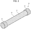
- Fig. 2 is a schematic perspective view illustrating a column. Incidentally, in Fig. 2 , for convenience of explanation, a covering part 13 is indicated by a dash-dot-dot line.
- the flow passage unit 1 has a column 10 for a liquid chromatograph and also has a support body 20 that supports the column 10.
- the column 10 has a stationary phase 11, which has a columnar outside shape and is porous, a pressure adjusting part 12, which is provided at least at a flow-in end 111 for a liquid, the flow-in end 111 being included in the stationary phase 11, and has a columnar outside shape and is porous, and the covering part 13 that covers the stationary phase 11 and pressure adjusting part 12.
- the stationary phase 11 has a function that performs an interaction (such as a hydrophobic interaction or an ion exchange) for each component of a sample that passes the stationary phase 11 and separates components from each other.
- the stationary phase 11 is formed from a porous body or an aggregate of fine particles.
- the material of the stationary phase 11 is selected from various types of ceramics, polymer molecules, and the like, depending on the type of the sample and the types of the components to be separated.
- the stationary phase 11 includes a sintered ceramic with a monolithic structure.
- porous silica for example, is included.
- silica monolith that is totally formed from integrated silica gel is used.
- the pressure adjusting part 12 has a function that adjusts the flow of a liquid. That is, the pressure adjusting part 12 has a porous body that has almost the same pressure loss as the stationary phase 11. By providing the pressure adjusting part 12, the flow of a liquid to be fed under pressure is adjusted, so disturbance of the liquid passing through the stationary phase 11 is suppressed.
- the pressure adjusting part 12 has a filter function and a function of a diffusing plate. In addition to this, the pressure adjusting part 12 has a harder material than the stationary phase 11.
- the pressure adjusting part 12 is provided at both the flow-in end 111 and flow-out end 112 of the stationary phase 11.
- a first plate 21 and a second plate 22 and the column 10 can be reliably placed in tight contact by the pressure adjusting parts 12 at two positions.
- a flow-in port 221 for a liquid is provided in the surface of the first plate 21.
- the flow-in port 221 is the inlet of the liquid flow passage 220.
- the liquid flow passage 220 extends from the flow-in port 221 to the same side as the second plate 22, is bent at a boundary position between the first plate 21 and the second plate 22, and communicates with the column holding part 210.
- a flow-out part 231 for a liquid is provided in the surface of the first plate 21.
- the flow-out part 231 is the outlet of the fluid flow passage 230.
- the fluid flow passage 230 extends from the flow-in port 221 to the same side as the second plate 22, is bent at a boundary position between the first plate 21 and the second plate 22, and communicates with the column holding part 210.
- a liquid passes from the flow-in port 221 through the liquid flow passage 220 and is fed to the column 10 in the column holding part 210.
- the liquid which has passed through the column 10, passes through the fluid flow passage 230 and is discharged from the flow-out part 222.
- liquid feeding withstand pressure can be improved (for example, a liquid feeding withstand pressure of 2 MPa or more).
- pressure more than necessary is not applied to the stationary phase 11 from the first plate 21 and second plate 22.
- the collapse of the porous holes in the stationary phase 11 is suppressed and sufficient analytical performance can be brought out.
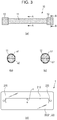
- Figs. 3(a) to 3(d) are schematic diagrams illustrating the dimensions of individual parts.
- the side surface of the column 10 is formed from the surface of the covering part 13.
- the shape of a cross-section at a portion of the column 10, the portion including the stationary phase 11, is substantially elliptical (see Fig. 3 (b) ).
- the shape of a cross-section at a portion of the column 10, the portion including the pressure adjusting part 12, is also substantially elliptical (see Fig. 3 (c) ).
- the shape of the cross-section of the column holding part 210 is substantially circular.
- the average diameter (referred to below as the “average diameter of the stationary phase portion”) of the cross-section at the portion of the column 10, the portion including the stationary phase 11, will be denoted a
- the average diameter (referred to below as “the average diameter of the pressure adjusting portion") of the cross-section at the portion of the column 10, the portion including the pressure adjusting part 12 will be denoted b.
- the ratio (a1/a2) between the maximum diameter a1 of the stationary phase portion and the minimum diameter a2 of the stationary phase portion is about 1.0071.
- the ratio (b1/b2) between the maximum diameter b1 of the pressure adjusting portion and the minimum diameter b2 of the pressure adjusting portion is about 1.0173.
- the average diameter b of the pressure adjusting portion is larger than the average diameter a of the stationary phase portion.
- b/a is larger than 1 and is equal to or smaller than 1.1 times.
- b/a is larger than 1.0 and is equal to or smaller than 1.05. More preferably, b/a is equal to or larger than 1.012 and is equal to or smaller than 1.020.
- the minimum diameter b2 of the pressure adjusting portion is larger than the minimum diameter a2 of the stationary phase portion.
- a state in which the outer diameter of the pressure adjusting part is smaller than the inner diameter of the column holding part 210 (a schematic cross-section of a portion of the stationary phase 11 as viewed in the axial direction of the column 10) is indicated.
- the covering part 13 is expanded by the pressure of the liquid and a clearance is generated between the covering part 13 and the stationary phase 11.
- part of the liquid passing through the stationary phase 11 leaks into the clearance between the covering part 13 and the stationary phase 11 in the course of passage. That is, it is not possible to obtain analytical performance as a column.
- Figs. 5(b) and 5(c) examples of liquid chromatograms analyzed in the state of the column indicated in Fig. 5(a) are indicated.
- Fig. 5(b) a case in which the pressure of the liquid is low is indicated.
- Fig. 5(c) a case in which the pressure of the liquid is high is indicated.
- the pressure of the liquid becomes high, the clearance between the covering part 13 and the stationary phase 11 is expanded and the liquid that leaks is increased.
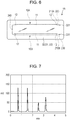
- Fig. 6 is a schematic plan view illustrating another example of the structure of the flow passage unit.
- This flow passage unit 1B has a structure in which a plurality of columns 10A and 10B are supported by the support body 20.
- the two columns 10A and 10B are supported by the support body 20.
- the support body 20 is provided with a column holding part 210A to hold the column 10A and a column holding part 210B to hold the column 10B.
- the column holding part 210A communicates with the liquid flow passage 220, and the column holding part 210B communicates with the fluid flow passage 230.
- a fluid flow passage 240 is provided between the column holding part 210A and the column holding part 210B.
- the two column holding parts 210A and 210B are provided in parallel.
- the U-shaped fluid flow passage 240 is provided between them.
- a liquid that has been fed from the flow-in port 221 to the liquid flow passage 220 passes through the column 10A, and is then fed from the fluid flow passage 240 to the column 10B.
- the liquid passes through the column 10B and is discharged from the flow-out part 231 through the fluid flow passage 230. Due to this flow passage unit 1B, analysis is performed in a state in which the two columns 10A and 10B are connected in series.
- the structures of the columns 10A and 10B used in the flow passage unit 1B are similar to the structure of the column 10 used in the flow passage unit 1.
- the pressure adjusting part 12 used in each of the columns 10A and 10B tight contact with the support body 20 can be assured, withstand pressure can be made high, and analytical performance can be made high.
- Fig. 7 is a diagram illustrating a liquid chromatogram using a flow passage unit according to a first example.
- the analytical conditions are the same in the examples and comparative examples described below as well.
- the theoretical plate number (theoretical plate number for the peak waveform with the longest hold time; the same applies hereinafter) is 12525
- the symmetry factor (symmetry factor for the peak waveform with the longest hold time; the same applies hereinafter)
- withstand pressure is 10.1 megapascals (MPa).
- the maximum diameter of the stationary phase portion is denoted a1
- the minimum diameter of the pressure adjusting portion is denoted b2
- the inner diameter of the column holding part 210 is denoted c
- a liquid chromatogram in a case in which the flow rate of the liquid to the flow passage unit 1 according to the second example is 0.4 ml/min is indicated.
- the theoretical plate number is 13335
- the symmetry factor is 1.083
- pressure is 7.1 MPa.
- a liquid chromatogram in a case in which the flow rate of the liquid to the flow passage unit 1 according to the second example is 0.6 ml/min is indicated.
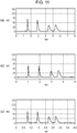
- Figs. 9(a) and 9(b) are diagrams illustrating liquid chromatograms using a flow passage unit according to a third example.
- a liquid chromatogram in a case in which the flow rate of the liquid to the flow passage unit 1 according to the third example is 0.4 ml/min is indicated.
- the theoretical plate number is 14599
- the symmetry factor is 1.075
- pressure is 6.3 MPa.
- a liquid chromatogram in a case in which the flow rate of the liquid to the flow passage unit 1 according to the third example is 0.6 ml/min is indicated.
- the theoretical plate number is 13347
- the symmetry factor is 1.103
- pressure is 10.0 MPa.
- a liquid chromatogram in a case in which the flow rate of the liquid to the flow passage unit according to the first comparative example is 0.2 ml/min is indicated.
- the theoretical plate number is 6369
- the symmetry factor is 1.36
- pressure is 3.1 MPa.
- a liquid chromatogram in a case in which the flow rate of the liquid to the flow passage unit according to the first comparative example is 0.3 ml/min is indicated.
- the theoretical plate number is 6464
- the symmetry factor is 1.43
- pressure is 4.5 MPa.
- Figs. 11(a) to 11(c) are diagrams illustrating liquid chromatograms using a flow passage unit according to a second comparative example.
- a liquid chromatogram in a case in which the flow rate of the liquid to the flow passage unit according to the second comparative example is 0.2 ml/min is indicated.
- the theoretical plate number is 2080
- the symmetry factor is 2.06
- pressure is 4.1 MPa.
- the scope of the present invention also includes embodiments obtained as a result of adding or deleting constituent element to or from the embodiments and other exemplary structures described above, performing design changes to them, or appropriately combining the features of the embodiment and other exemplary structures as long as the obtained embodiments are within the intended scope of the present invention; the additions, deletions, design changes, or combination is effected by a person having ordinary skill in the art.
Landscapes
- Chemical & Material Sciences (AREA)
- Analytical Chemistry (AREA)
- Chemical Kinetics & Catalysis (AREA)
- Organic Chemistry (AREA)
- Biochemistry (AREA)
- Life Sciences & Earth Sciences (AREA)
- Health & Medical Sciences (AREA)
- General Health & Medical Sciences (AREA)
- General Physics & Mathematics (AREA)
- Immunology (AREA)
- Pathology (AREA)
- Physics & Mathematics (AREA)
- Dispersion Chemistry (AREA)
- Inorganic Chemistry (AREA)
- Treatment Of Liquids With Adsorbents In General (AREA)
Abstract
Description
- The present invention relates to a flow passage unit that has a column for a liquid chromatograph and also has a support body that supports the column.
- Liquid chromatography is an analysis method in which an eluant, which is a mobile phase, is injected into a column having a stationary phase such as a porous body together with a sample and qualitative analysis and quantitative analysis are performed on the basis that the components of a sample are separated into individual components in the stationary phase.
- In
PTL 1, a microchannel device is disclosed that has a structure making a liquid or gas less likely to leach out to the outside of a processing body. In this microchannel device, the processing body has a covering layer, made of a synthetic resin, that encloses a porous body. Therefore, air-tightness and liquid-tightness between the porous body and the inner surface of a main body can be made high, and the porous body enables fluids to be mixed and react efficiently. - PTL 1: International Publication No.
2013/121889 - However, in a flow passage unit that supports a column by sandwiching it between plates, if tight contact between the plate and the column is low, liquid feeding withstand pressure is lowered. On the other hand, although liquid feeding withstand pressure is raised by making tight contact between the plate and the column high, the column is collapsed more than necessary and the passing of the liquid is impeded. In either case, reduction in a theoretical plate number and deterioration in a symmetry factor are caused in analysis.
- An object of the present invention is to provide a flow passage unit that can achieve both improvement in liquid feeding withstand pressure and improvement in analytical performance.
- To solve the above problems, a flow passage unit in the present invention is a flow passage unit that has a column for a liquid chromatograph and also has a support body that supports the column. The flow passage unit is characterized in that: the column has a porous stationary phase, a porous pressure adjusting part provided at least at a flow-in end for a liquid, the flow-in end being included in the stationary phase, the pressure adjusting part being harder than the stationary phase, and a covering part that covers the stationary phase and pressure adjusting part; the support body has a first plate and a second plate that are mutually joined, the support body forming a column holding part and a liquid flow passage, the column holding part holding the column between the first plate and the second plate, the liquid flow passage communicating with the column holding part; and pressure applied from the first plate and second plate to the pressure adjusting part is higher than pressure applied to the stationary phase.
- According to the structure like this, the liquid fed under pressure to the liquid flow passage is fed to the stationary phase while the pressure of the liquid is adjusted by the pressure adjusting part. Thus, the unevenness of the liquid passing through the stationary phase is suppressed. Since tight contact at the position of the pressure adjusting part is increased in a state in which the column is held between the first plate and the second plate, liquid feeding withstand pressure can be improved. On the other hand, pressure more than necessary is not applied to the stationary phase. Therefore, the collapse of the porous holes is suppressed and sufficient analytical performance can be brought out.
- In the flow passage unit in the present invention, porous holes in the vicinity of the outer circumference of the pressure adjusting part may be smaller than porous holes at the central portion. Thus, it is possible to assure tight contact between the first and second plates and the pressure adjusting part and to assure the functions of the pressure adjusting part.
- In the flow passage unit in the present invention, the pressure adjusting part may be provided at both the flow-in end and a flow-out end, the flow-in end and the flow-out end being included in the stationary phase. Thus, it is possible to reliably bring the first and second plates into tight contact with each other by the pressure adjusting parts at two positions.
- In the flow passage unit in the present invention, in a state in which the column is not supported by the support body, the average diameter of a cross-section at a portion of the column, the portion including the pressure adjusting part, may be larger than 1 times the average diameter of a cross-section at a portion of the column, the portion including the stationary phase, and may be smaller than or equal to 1.1 times. Moreover, the maximum diameter of the cross-section at the portion of the column, the portion including the stationary phase, may be larger than or equal to 0.96 and may be smaller than 1.0, with respect to the inner diameter of the column holding part. Moreover, the minimum diameter of the cross-section at the portion of the column, the portion including the pressure adjusting part, may be larger than 1 times the inner diameter of the column holding part and may be smaller than 1.06 times. Thus, it is possible to enhance tight contact between the first and second plates and the pressure adjusting part and to prevent a flow of the liquid passing through the stationary phase from being impeded.
- In the flow passage unit in the present invention, withstand pressure when a liquid is caused to flow into the liquid flow passage may be 2 megapascals or higher. Thus, highly precise analysis can be performed in a short time.
- In the flow passage unit in the present invention, the stationary phase may include a sintered ceramic with a monolithic structure. As this sintered ceramic, porous silica may be included. Moreover, the first plate and second plate each may be formed from a synthetic resin.
- In the flow passage unit in the present invention, the covering part may be formed from, for example, a heat-shrinkable resin, which shrinks due to heating. The heat-shrinkable resin may include polyetheretherketone. In this case, withstand pressure when a liquid is caused to flow into the liquid flow passage may be 10 megapascals or higher. Thus, highly precise analysis can be performed in an extremely short time.
- According to the present invention, it becomes possible to provide a flow passage unit that can achieve both improvement in liquid feeding withstand pressure and improvement in analytical performance.
-
- [
Fig. 1] Figs. 1(a) and 1(b) are schematic diagrams illustrating a flow passage unit according to a first embodiment. - [
Fig. 2] Fig. 2 is a schematic perspective view illustrating a column. - [
Fig. 3] Figs. 3(a) to 3(d) are schematic diagrams illustrating the dimensions of individual parts. - [
Fig. 4] Figs. 4(a) and 4(b) illustrate a state of the column and an example of a liquid chromatogram. - [
Fig. 5] Figs. 5(a) to 5(c) illustrate a state of the column and examples of liquid chromatograms. - [
Fig. 6] Fig. 6 is a schematic plan view illustrating another example of the structure of the flow passage unit. - [
Fig. 7] Fig. 7 is a diagram illustrating a liquid chromatogram using a flow passage unit according to a first example. - [
Fig. 8] Figs. 8(a) and 8(b) are diagrams illustrating liquid chromatograms using a flow passage unit according to a second example. - [
Fig. 9] Figs. 9(a) and 9(b) are diagrams illustrating liquid chromatograms using a flow passage unit according to a third example. - [
Fig. 10] Figs. 10(a) and 10(b) are diagrams illustrating liquid chromatograms using a flow passage unit according to a first comparative example. - [
Fig. 11] Figs. 11(a) to 11(c) are diagrams illustrating liquid chromatograms using a flow passage unit according to a second comparative example. - Embodiments of the present invention will be described below according to the drawings. Incidentally, in the descriptions below, like elements will be denoted by like reference numerals and descriptions will be appropriately omitted for members that have been described once.
-
Figs. 1(a) and 1(b) are schematic diagrams illustrating a flow passage unit according to a first embodiment. - In
Fig. 1(a) , a plan view of theflow passage unit 1 is indicated. InFig. 1(b) , an enlarged cross-sectional view of the portion A indicated inFig. 1(a) is indicated. -
Fig. 2 is a schematic perspective view illustrating a column. Incidentally, inFig. 2 , for convenience of explanation, a coveringpart 13 is indicated by a dash-dot-dot line. - As indicated in
Figs. 1(a) and 1(b) , theflow passage unit 1 according to this embodiment has acolumn 10 for a liquid chromatograph and also has asupport body 20 that supports thecolumn 10. - The
column 10 has astationary phase 11, which has a columnar outside shape and is porous, apressure adjusting part 12, which is provided at least at a flow-inend 111 for a liquid, the flow-inend 111 being included in thestationary phase 11, and has a columnar outside shape and is porous, and the coveringpart 13 that covers thestationary phase 11 andpressure adjusting part 12. - The
stationary phase 11 has a function that performs an interaction (such as a hydrophobic interaction or an ion exchange) for each component of a sample that passes thestationary phase 11 and separates components from each other. Thestationary phase 11 is formed from a porous body or an aggregate of fine particles. The material of thestationary phase 11 is selected from various types of ceramics, polymer molecules, and the like, depending on the type of the sample and the types of the components to be separated. In this embodiment, thestationary phase 11 includes a sintered ceramic with a monolithic structure. As the sintered ceramic, porous silica, for example, is included. In particular, silica monolith that is totally formed from integrated silica gel is used. - The
pressure adjusting part 12 has a function that adjusts the flow of a liquid. That is, thepressure adjusting part 12 has a porous body that has almost the same pressure loss as thestationary phase 11. By providing thepressure adjusting part 12, the flow of a liquid to be fed under pressure is adjusted, so disturbance of the liquid passing through thestationary phase 11 is suppressed. - Moreover, the
pressure adjusting part 12 has a filter function and a function of a diffusing plate. In addition to this, thepressure adjusting part 12 has a harder material than thestationary phase 11. - In this embodiment, the
pressure adjusting part 12 is provided at both the flow-inend 111 and flow-outend 112 of thestationary phase 11. Thus, afirst plate 21 and asecond plate 22 and thecolumn 10 can be reliably placed in tight contact by thepressure adjusting parts 12 at two positions. - A heat-shrinkable resin, which shrinks due to heating, for example, is used for the covering
part 13. The coveringpart 13 is tubular. By accommodating thestationary phase 11 andpressure adjusting parts 12 in this tube and then heating thecovering part 13, thecolumn 10 having a columnar outer shape is structured. The type of the heat-shrinkable resin is not limited. Tetrafluoroethylene-hexafluoropropylene copolymer (4, 6 fluorinated, FEP), polyetheretherketone (PEEK), and the like are exemplified. When a liquid is supplied from aliquid flow passage 220 into acolumn holding part 210, a pressure of several MPa or more is applied to the interior of thecolumn 10. In this case as well, from the viewpoint of making a clearance less likely to be generated between thestationary phase 11 and the coveringpart 13, it is preferable to use PEEK as the heat-shrinkable resin. By using PEEK as the heat-shrinkable resin, even if the pressure of the liquid becomes 10 megapascals (MPa) higher, a leading, which will be described later, is less likely to appear in a waveform. - The
support body 20 has thefirst plate 21 andsecond plate 22 that are mutually joined. By mutually joining thefirst plate 21 andsecond plate 22, acolumn holding part 210 and afluid flow passages column holding part 210 are formed. Thecolumn holding part 210 is a space in which thecolumn 10 is accommodated. Thecolumn 10 is placed in thecolumn holding part 210 and is sandwiched between thefirst plate 21 and thesecond plate 22. - A flow-in
port 221 for a liquid is provided in the surface of thefirst plate 21. The flow-inport 221 is the inlet of theliquid flow passage 220. Theliquid flow passage 220 extends from the flow-inport 221 to the same side as thesecond plate 22, is bent at a boundary position between thefirst plate 21 and thesecond plate 22, and communicates with thecolumn holding part 210. - A flow-out
part 231 for a liquid is provided in the surface of thefirst plate 21. The flow-outpart 231 is the outlet of thefluid flow passage 230. Thefluid flow passage 230 extends from the flow-inport 221 to the same side as thesecond plate 22, is bent at a boundary position between thefirst plate 21 and thesecond plate 22, and communicates with thecolumn holding part 210. - A liquid passes from the flow-in
port 221 through theliquid flow passage 220 and is fed to thecolumn 10 in thecolumn holding part 210. The liquid, which has passed through thecolumn 10, passes through thefluid flow passage 230 and is discharged from the flow-out part 222. - For the
first plate 21 andsecond plate 22, a synthetic resin, for example, is used. As a synthetic resin, a cyclic polyolefin resin (COP), for example, is used. Thefirst plate 21 andsecond plate 22 are joined by, for example, thermal compression bonding. Moreover, thefirst plate 21 andsecond plate 22 may be joined with an adhesive such as an ultraviolet curable resin. - With the
flow passage unit 1 according to this embodiment, in a state in which thecolumn 10 is sandwiched between thefirst plate 21 and thesecond plate 22, pressure applied from thefirst plate 21 andsecond plate 22 to thepressure adjusting part 12 is higher than pressure applied to thestationary phase 11. This difference in pressure can be measured with a strain measuring device as stress to thefirst plate 21 andsecond plate 22. - That is, in a state in which the
column 10 is sandwiched between thefirst plate 21 and thesecond plate 22, tight contact between thefirst plate 21 and thesecond plate 22 is higher at the position of thepressure adjusting part 12 than at the position of thestationary phase 11. Thus, liquid feeding withstand pressure can be improved (for example, a liquid feeding withstand pressure of 2 MPa or more). On the other hand, pressure more than necessary is not applied to thestationary phase 11 from thefirst plate 21 andsecond plate 22. Thus, the collapse of the porous holes in thestationary phase 11 is suppressed and sufficient analytical performance can be brought out. -
Figs. 3(a) to 3(d) are schematic diagrams illustrating the dimensions of individual parts. - In
Fig. 3(a) , thecolumn 10 is illustrated. InFig. 3(b) , dimensions at the line A-A cross-section inFig. 3(a) are illustrated. InFig. 3(c) , dimensions at the line B-B cross-section inFig. 3(a) are illustrated. Furthermore, inFig. 3(d) , a dimension of thecolumn holding part 210 in thesupport body 20 is illustrated. Incidentally, inFig. 3(a) , thecolumn 10 that is not supported by thesupport body 20 is illustrated. - The side surface of the
column 10 is formed from the surface of the coveringpart 13. In a state in which thecolumn 10 is not supported by thecolumn holding part 210, the shape of a cross-section at a portion of thecolumn 10, the portion including thestationary phase 11, is substantially elliptical (seeFig. 3 (b) ). The shape of a cross-section at a portion of thecolumn 10, the portion including thepressure adjusting part 12, is also substantially elliptical (seeFig. 3 (c) ). Moreover, the shape of the cross-section of thecolumn holding part 210 is substantially circular. - In
Fig. 3(b) , a1 indicates the maximum diameter (referred to below as the "maximum diameter of the stationary phase portion") of the cross-section at the portion of thecolumn 10, the portion including thestationary phase 11, and a2 indicates the minimum diameter (referred to below as the "minimum diameter of the stationary phase portion") of the cross-section at the portion of thecolumn 10, the portion including thestationary phase 11. InFig. 3(c) , b1 indicates the maximum diameter (referred to below as the "maximum diameter of the pressure adjusting portion") of the cross-section at the portion of thecolumn 10, the portion including thepressure adjusting part 12, and b2 indicates the minimum diameter (referred to below as the "minimum diameter of the pressure adjusting portion") of the cross-section at the portion of thecolumn 10, the portion including thepressure adjusting part 12. InFig. 3(d), c indicates the inner diameter of thecolumn holding part 210. - Incidentally, the average diameter (referred to below as the "average diameter of the stationary phase portion") of the cross-section at the portion of the
column 10, the portion including thestationary phase 11, will be denoted a, and the average diameter (referred to below as "the average diameter of the pressure adjusting portion") of the cross-section at the portion of thecolumn 10, the portion including thepressure adjusting part 12, will be denoted b. - In the above dimensions, the ratio (a1/a2) between the maximum diameter a1 of the stationary phase portion and the minimum diameter a2 of the stationary phase portion is about 1.0071. The ratio (b1/b2) between the maximum diameter b1 of the pressure adjusting portion and the minimum diameter b2 of the pressure adjusting portion is about 1.0173. The average diameter b of the pressure adjusting portion is larger than the average diameter a of the stationary phase portion. Specifically, b/a is larger than 1 and is equal to or smaller than 1.1 times. Preferably, b/a is larger than 1.0 and is equal to or smaller than 1.05. More preferably, b/a is equal to or larger than 1.012 and is equal to or smaller than 1.020. Moreover, the minimum diameter b2 of the pressure adjusting portion is larger than the minimum diameter a2 of the stationary phase portion.
- Moreover, it is desirable for the maximum diameter a1 of the stationary phase portion to be smaller than the inner diameter c of the
column holding part 210. Specifically, a1/c is equal to or larger than 0.96 and is smaller than 1.0; preferably, a1/c is equal to or larger than 0.980 and is equal to or smaller than 0.988. - Moreover, it is desirable for the minimum diameter b2 of the pressure adjusting portion to be larger than the inner diameter c of the
column holding part 210. Specifically, b2/c is larger than 1.0 and is equal to or smaller than 1.06; preferably, b2/c is equal to or larger than 1.008 and is equal to or smaller than 1.020. - Examples of specific dimensions will be indicated below.
- Average diameter a of the stationary phase portion = 2.419 mm
- Maximum diameter a1 of the stationary phase portion = 2.427 mm
- Minimum diameter a2 of the stationary phase portion = 2.410 mm
- Average diameter b of the pressure adjusting portion = 2.512 mm
- Maximum diameter b1 of the pressure adjusting portion = 2.533 mm
- Minimum diameter b2 of the pressure adjusting portion = 2.490 mm
- Inner diameter c of the
column holding part 210 = 2.44 mm (±0.02 mm) - When the dimensions of the
column 10 andcolumn holding part 210 are set like this and thecolumn 10 is accommodated in thecolumn holding part 210 and is then sandwiched between thefirst plate 21 and thesecond plate 22, thepressure adjusting part 12 is appropriately collapsed and the side surface of the portion of thecolumn 10, the portion including thepressure adjusting part 12, is placed in tight contact with thefirst plate 21 andsecond plate 22. In this case, porous holes in the vicinity of the outer circumference of thepressure adjusting part 12 become smaller than porous holes at the central portion. That is, thepressure adjusting part 12 is in a state in which porous holes at the central portion are not collapsed, and only porous holes in the vicinity of the outer circumference are slightly collapsed. - On the other hand, force more than necessary is not applied from the
first plate 21 andsecond plate 22 to thestationary phase 11. Due to the state like this, it is possible to enhance tight contact between thefirst plate 21 andsecond plate 22 and the portion of thecolumn 10, the portion including thepressure adjusting part 12, and to prevent a flow of the liquid passing through thestationary phase 11 from being impeded. - Here, a case in which tight contact between the
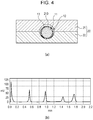
column 10 and thesupport body 20 is insufficient will be descried. - In
Fig. 4(a) , a state in which the outer diameter of thecolumn 10 is smaller than the inner diameter of the column holding part 210 (a schematic cross-section of a portion of thestationary phase 11 as viewed in the axial direction of the column 10) is indicated. In this state, a clearance is generated between thecolumn 10 and thesupport body 20. In this case, part of the liquid fed under pressure passes through clearances between the coveringpart 13 and thefirst plate 21 andsecond plate 22. - In
Fig. 4(b) , an example of a liquid chromatogram analyzed in the state of thecolumn 10 indicated inFig. 4(a) is indicated. Since the liquid passes through the clearances between the coveringpart 13 and thefirst plate 21 andsecond plate 22, a waveform peak appears near t = 0. - In
Fig. 5(a) , a state in which the outer diameter of the pressure adjusting part is smaller than the inner diameter of the column holding part 210 (a schematic cross-section of a portion of thestationary phase 11 as viewed in the axial direction of the column 10) is indicated. In this state, the coveringpart 13 is expanded by the pressure of the liquid and a clearance is generated between the coveringpart 13 and thestationary phase 11. In this case, part of the liquid passing through thestationary phase 11 leaks into the clearance between the coveringpart 13 and thestationary phase 11 in the course of passage. That is, it is not possible to obtain analytical performance as a column. - In
Figs. 5(b) and 5(c) , examples of liquid chromatograms analyzed in the state of the column indicated inFig. 5(a) are indicated. InFig. 5(b) , a case in which the pressure of the liquid is low is indicated. InFig. 5(c) , a case in which the pressure of the liquid is high is indicated. When the pressure of the liquid becomes high, the clearance between the coveringpart 13 and thestationary phase 11 is expanded and the liquid that leaks is increased. Thus, a leading appears on a waveform. That is, when the pressure of the liquid becomes high, sufficient analytical performance cannot be obtained, so withstand pressure cannot be made high. - In this embodiment, tight contact with the
support body 20 can be obtained with thepressure adjusting part 12 of thecolumn 10. Thus, withstand pressure can be made high while ensuring sufficient analytical performance. -
Fig. 6 is a schematic plan view illustrating another example of the structure of the flow passage unit. - This
flow passage unit 1B has a structure in which a plurality ofcolumns support body 20. In the example indicated inFig. 6 , the twocolumns support body 20. Thesupport body 20 is provided with acolumn holding part 210A to hold thecolumn 10A and acolumn holding part 210B to hold thecolumn 10B. Thecolumn holding part 210A communicates with theliquid flow passage 220, and thecolumn holding part 210B communicates with thefluid flow passage 230. Afluid flow passage 240 is provided between thecolumn holding part 210A and thecolumn holding part 210B. - In this
flow passage unit 1B, the twocolumn holding parts fluid flow passage 240 is provided between them. Thus, a liquid that has been fed from the flow-inport 221 to theliquid flow passage 220 passes through thecolumn 10A, and is then fed from thefluid flow passage 240 to thecolumn 10B. Then, the liquid passes through thecolumn 10B and is discharged from the flow-outpart 231 through thefluid flow passage 230. Due to thisflow passage unit 1B, analysis is performed in a state in which the twocolumns - The structures of the
columns flow passage unit 1B are similar to the structure of thecolumn 10 used in theflow passage unit 1. Thus, due to thepressure adjusting part 12 used in each of thecolumns support body 20 can be assured, withstand pressure can be made high, and analytical performance can be made high. - Next, examples and comparative examples will be described.
-
Fig. 7 is a diagram illustrating a liquid chromatogram using a flow passage unit according to a first example. - Measurement conditions in high performance liquid chromatography (HPLC) are as follows.
- The analytical conditions are the same in the examples and comparative examples described below as well.
- Analyzing apparatus: LC-2010AHT manufactured by Shimadzu Corporation
- Sample: uracil, methyl benzoate, toluene, and naphthalene
- Amount of injection: 0.2 µL, column oven temperature: 25°C
- Mobile phase: Acetonitrile/water = 60/40 (vol/vol)
- Detection: UV detector, 254 nm, semi-micro cell
- In the first example, a structure as described below is used as the
flow passage unit 1B. - If the maximum diameter of the stationary phase portion is denoted a1, the minimum diameter of the pressure adjusting portion is denoted b2, and the inner diameter of the
column holding part 210 is denoted c, then b2 - c is +40 micrometers (µm) and a1 - c is -48 µm. The flow rate of the liquid to theflow passage unit 1 according to the first example is 0.4 milliliter/minute (ml/min). - In this example, the theoretical plate number (theoretical plate number for the peak waveform with the longest hold time; the same applies hereinafter) is 12525, the symmetry factor (symmetry factor for the peak waveform with the longest hold time; the same applies hereinafter) is 1.08, and withstand pressure is 10.1 megapascals (MPa).
-
Figs. 8(a) and 8(b) are diagrams illustrating liquid chromatograms using a flow passage unit according to a second example. - In the second example, a structure as described below is used as the
flow passage unit 1B. - If the maximum diameter of the stationary phase portion is denoted a1, the minimum diameter of the pressure adjusting portion is denoted b2, and the inner diameter of the
column holding part 210 is denoted c, then b2 - c is +21 µm and a1 - c is -41 µm. - In
Fig. 8(a) , a liquid chromatogram in a case in which the flow rate of the liquid to theflow passage unit 1 according to the second example is 0.4 ml/min is indicated. - In this example, the theoretical plate number is 13335, the symmetry factor is 1.083, and pressure is 7.1 MPa.
- In
Fig. 8(b) , a liquid chromatogram in a case in which the flow rate of the liquid to theflow passage unit 1 according to the second example is 0.6 ml/min is indicated. - In this example, the theoretical plate number is 12697, the symmetry factor is 1.101, and pressure is 11.6 MPa.
- That is, even if the flow rate is increased from 0.4 ml/min to 0.6 ml/min, a sufficient theoretical plate number, a sufficient symmetry factor, and sufficient withstand pressure can be obtained.
-
Figs. 9(a) and 9(b) are diagrams illustrating liquid chromatograms using a flow passage unit according to a third example. - In the third example, a structure as described below is used as the
flow passage unit 1B. - If the maximum diameter of the stationary phase portion is denoted a1, the minimum diameter of the pressure adjusting portion is denoted b2, and the inner diameter of the
column holding part 210 is denoted c, then b2 - c is +28 µm and a1 - c is -27 µm. - In
Fig. 9(a) , a liquid chromatogram in a case in which the flow rate of the liquid to theflow passage unit 1 according to the third example is 0.4 ml/min is indicated. - In this example, the theoretical plate number is 14599, the symmetry factor is 1.075, and pressure is 6.3 MPa.
- In
Fig. 9(b) , a liquid chromatogram in a case in which the flow rate of the liquid to theflow passage unit 1 according to the third example is 0.6 ml/min is indicated. - In this example, the theoretical plate number is 13347, the symmetry factor is 1.103, and pressure is 10.0 MPa.
- That is, even if the flow rate is increased from 0.4 ml/min to 0.6 ml/min, a sufficient theoretical plate number, a sufficient symmetry factor, and sufficient withstand pressure can be obtained.
-
Figs. 10(a) and 10(b) are diagrams illustrating liquid chromatograms using a flow passage unit according to a first comparative example. - In the first comparative example, a structure as described below is used as the flow passage unit.
- If the maximum diameter of the stationary phase portion is denoted a1, the minimum diameter of the pressure adjusting portion is denoted b2, and the inner diameter of the
column holding part 210 is denoted c, then b2 - c is +36 µm and a1 - c is +35 µm. - In
Fig. 10(a) , a liquid chromatogram in a case in which the flow rate of the liquid to the flow passage unit according to the first comparative example is 0.2 ml/min is indicated. - In this example, the theoretical plate number is 6369, the symmetry factor is 1.36, and pressure is 3.1 MPa.
- In
Fig. 10(b) , a liquid chromatogram in a case in which the flow rate of the liquid to the flow passage unit according to the first comparative example is 0.3 ml/min is indicated. - In this example, the theoretical plate number is 6464, the symmetry factor is 1.43, and pressure is 4.5 MPa.
-
Figs. 11(a) to 11(c) are diagrams illustrating liquid chromatograms using a flow passage unit according to a second comparative example. - In the second comparative example, a structure as described below is used as the flow passage unit.
- If the maximum diameter of the stationary phase portion is denoted a1, the minimum diameter of the pressure adjusting portion is denoted b2, and the inner diameter of the
column holding part 210 is denoted c, then b2 - c is +36 µm and a1 - c is +22 µm. - In
Fig. 11(a) , a liquid chromatogram in a case in which the flow rate of the liquid to the flow passage unit according to the second comparative example is 0.2 ml/min is indicated. - In this example, the theoretical plate number is 1861, the symmetry factor is 1.36, and pressure is 2.7 MPa.
- In
Fig. 11(b) , a liquid chromatogram in a case in which the flow rate of the liquid to the flow passage unit according to the second comparative example is 0.3 ml/min is indicated. - In this example, the theoretical plate number is 2080, the symmetry factor is 2.06, and pressure is 4.1 MPa.
- In
Fig. 11(c) , a liquid chromatogram in a case in which the flow rate of the liquid to the flow passage unit according to the second comparative example is 0.4 ml/min is indicated. - In this example, the theoretical plate number is 2094, the symmetry factor is 2.02, and pressure is 5.4 MPa.
- As described above, according to the embodiments, it is possible to provide a flow passage unit that can achieve both improvement in liquid feeding withstand pressure and improvement in analytical performance.
- Incidentally, although embodiments and other exemplary structures have been described above, the present invention is not limited to these examples. In these embodiments, for example, flow passage units that use one or two columns have been exemplified, but even a flow passage unit that uses three or more columns is also applicable. Although, in these embodiments, the axis of the columnar column is linear, this is not a limitation. The axis of the column may have a bent portion. In addition, the scope of the present invention also includes embodiments obtained as a result of adding or deleting constituent element to or from the embodiments and other exemplary structures described above, performing design changes to them, or appropriately combining the features of the embodiment and other exemplary structures as long as the obtained embodiments are within the intended scope of the present invention; the additions, deletions, design changes, or combination is effected by a person having ordinary skill in the art.
-
- 1, 1B
- flow passage unit
- 10, 10A, 10B
- column
- 11
- stationary phase
- 12
- pressure adjusting part
- 13
- covering part
- 20
- support body
- 21
- first plate
- 22
- second plate
- 111
- flow-in end
- 112
- flow-out end
- 210, 210A, 210B
- column holding part
- 220
- liquid flow passage
- 221
- flow-in port
- 231
- flow-out part
- 230, 240
- fluid flow passage
Claims (13)
- A flow passage unit that has a column for a liquid chromatograph and also has a support body that supports the column, wherein:the column hasa porous stationary phase,a porous pressure adjusting part provided at least at a flow-in end for a liquid, the flow-in end being included in the stationary phase, the pressure adjusting part being harder than the stationary phase, anda covering part that covers the stationary phase and the pressure adjusting part;the support body has a first plate and a second plate that are mutually joined, the support body forming a column holding part and a liquid flow passage, the column holding part holding the column between the first plate and the second plate, the liquid flow passage communicating with the column holding part; andpressure applied from the first plate and the second plate to the pressure adjusting part is higher than pressure applied to the stationary phase.
- The flow passage unit according to Claim 1, wherein a porous hole near an outer circumference of the pressure adjusting part is smaller than a porous hole at a central portion.
- The flow passage unit according to Claim 1 or Claim 2, wherein the pressure adjusting part is provided at both the flow-in end and a flow-out end for the liquid, the flow-in end and the flow-out end being included in the stationary phase.
- The flow passage unit according to any one of Claim 1 to Claim 3, wherein in a state in which the column is not supported by the support body, an average diameter of a cross-section at a portion of the column, the portion including the pressure adjusting part, is larger than 1 times an average diameter of a cross-section at a portion of the column, the portion including the stationary phase, and is smaller than or equal to 1.1 times.
- The flow passage unit according to any one of Claim 1 to Claim 4, wherein a maximum diameter of a cross-section at a portion of the column, the portion including the stationary phase, is larger than or equal to 0.96 and is smaller than 1.0, with respect to an inner diameter of the column holding part.
- The flow passage unit according to any one of Claim 1 to Claim 5, wherein a minimum diameter of a cross-section at a portion of the column, the portion including the pressure adjusting part, is larger than 1 times the inner diameter of the column holding part and is smaller than 1.06 times.
- The flow passage unit according to any one of Claim 1 to Claim 6, wherein withstand pressure when the liquid is caused to flow into the liquid flow passage is 2 megapascals or higher.
- The flow passage unit according to any one of Claim 1 to Claim 6, wherein the stationary phase includes a sintered ceramic with a monolithic structure.
- The flow passage unit according to Claim 8, wherein the sintered ceramic includes porous silica.
- The flow passage unit according to any one of Claim 1 to Claim 9, wherein the first plate and the second plate each are formed from a synthetic resin.
- The flow passage unit according to any one of Claim 1 to Claim 10, wherein the covering part is formed from a heat-shrinkable resin, which shrinks due to heating.
- The flow passage unit according to Claim 11, wherein the heat-shrinkable resin includes polyetheretherketone.
- The flow passage unit according to Claim 12, wherein withstand pressure when the liquid is caused to flow into the liquid flow passage is 10 megapascals or higher.
Applications Claiming Priority (3)
| Application Number | Priority Date | Filing Date | Title |
|---|---|---|---|
| JP2015117791 | 2015-06-10 | ||
| JP2015256212A JP6650756B2 (en) | 2015-06-10 | 2015-12-28 | Channel unit |
| PCT/JP2016/064426 WO2016199542A1 (en) | 2015-06-10 | 2016-05-16 | Flow passage unit |
Publications (2)
| Publication Number | Publication Date |
|---|---|
| EP3309545A1 true EP3309545A1 (en) | 2018-04-18 |
| EP3309545A4 EP3309545A4 (en) | 2019-03-06 |
Family
ID=57754367
Family Applications (1)
| Application Number | Title | Priority Date | Filing Date |
|---|---|---|---|
| EP16807249.4A Withdrawn EP3309545A4 (en) | 2015-06-10 | 2016-05-16 | Flow passage unit |
Country Status (4)
| Country | Link |
|---|---|
| US (1) | US11125730B2 (en) |
| EP (1) | EP3309545A4 (en) |
| JP (1) | JP6650756B2 (en) |
| CN (1) | CN107636457B (en) |
Families Citing this family (5)
| Publication number | Priority date | Publication date | Assignee | Title |
|---|---|---|---|---|
| WO2018154932A1 (en) * | 2017-02-21 | 2018-08-30 | 株式会社島津製作所 | Liquid chromatograph mass spectrometer |
| JP6776451B2 (en) | 2017-07-12 | 2020-10-28 | アルプスアルパイン株式会社 | Analyzer and flow path plate |
| JP6854206B2 (en) * | 2017-07-12 | 2021-04-07 | アルプスアルパイン株式会社 | Flow path tip and flow path tip positioning method |
| EP3797278B1 (en) * | 2018-05-21 | 2025-06-25 | Waters Technologies Corporation | Micro solid phase extraction device with reinforced columns and corresponding extraction method |
| JP7585014B2 (en) | 2020-12-02 | 2024-11-18 | キヤノン株式会社 | LIQUID EJECTION HEAD, ITS OPERATION METHOD, AND LIQUID EJECTION APPARATUS |
Family Cites Families (16)
| Publication number | Priority date | Publication date | Assignee | Title |
|---|---|---|---|---|
| CN1174247C (en) * | 2001-06-06 | 2004-11-03 | 中国科学院大连化学物理研究所 | A column head/column tail structure of a zero-dead-volume fine-bore liquid chromatography column |
| JP3965283B2 (en) | 2001-07-02 | 2007-08-29 | 株式会社日立製作所 | Packet transfer device with multiple types of packet control functions |
| US6887384B1 (en) * | 2001-09-21 | 2005-05-03 | The Regents Of The University Of California | Monolithic microfluidic concentrators and mixers |
| KR100505361B1 (en) * | 2002-06-03 | 2005-08-03 | 정원조 | Stainless Steel Tubing/Frit With Sintered Inorganic Particles And A Chromathography Column Manufactured By Using The Same |
| US7364647B2 (en) * | 2002-07-17 | 2008-04-29 | Eksigent Technologies Llc | Laminated flow device |
| US7279134B2 (en) | 2002-09-17 | 2007-10-09 | Intel Corporation | Microfluidic devices with porous membranes for molecular sieving, metering, and separations |
| US7449165B2 (en) * | 2004-02-03 | 2008-11-11 | Ut-Battelle, Llc | Robust carbon monolith having hierarchical porosity |
| JP2006010327A (en) * | 2004-06-22 | 2006-01-12 | Kawamura Inst Of Chem Res | Micro-fluid device and injection method of very small amount of sample |
| CN201001975Y (en) * | 2006-07-14 | 2008-01-09 | 成都普瑞法科技开发有限公司 | High-efficient axial compressing preparing chromatographic column |
| WO2008009310A1 (en) * | 2006-07-17 | 2008-01-24 | Agilent Technologies, Inc. | Equlibrating a temperature profile in a column |
| GB0614315D0 (en) * | 2006-07-19 | 2006-08-30 | Ge Healthcare Bio Sciences Ab | Chromatography columns, systems and methods |
| JP2009069051A (en) * | 2007-09-14 | 2009-04-02 | Canon Inc | Manufacturing method of microfluidic device |
| US20090238722A1 (en) * | 2008-03-18 | 2009-09-24 | Agilent Technologies, Inc. | Pressure-Reinforced Fluidic Chip |
| JP5819513B2 (en) * | 2012-02-17 | 2015-11-24 | アルプス電気株式会社 | Micro-channel device and manufacturing apparatus thereof |
| JP6004370B2 (en) * | 2012-08-10 | 2016-10-05 | アルプス電気株式会社 | Channel unit used for liquid chromatograph |
| EP3204136B1 (en) * | 2014-10-05 | 2022-03-30 | RotaChrom Technológiai és Szolgáltató Zártkörüen Müködö Részvénytársaság | Novel type of extraction cell for a centrifugal partition chromatograph, as well as a centrifugal partition chromatograph containing such an extraction cell |
-
2015
- 2015-12-28 JP JP2015256212A patent/JP6650756B2/en active Active
-
2016
- 2016-05-16 CN CN201680033944.6A patent/CN107636457B/en active Active
- 2016-05-16 EP EP16807249.4A patent/EP3309545A4/en not_active Withdrawn
-
2017
- 2017-12-07 US US15/834,252 patent/US11125730B2/en active Active
Also Published As
| Publication number | Publication date |
|---|---|
| JP6650756B2 (en) | 2020-02-19 |
| US11125730B2 (en) | 2021-09-21 |
| EP3309545A4 (en) | 2019-03-06 |
| CN107636457B (en) | 2020-07-28 |
| JP2017003562A (en) | 2017-01-05 |
| CN107636457A (en) | 2018-01-26 |
| US20180100836A1 (en) | 2018-04-12 |
Similar Documents
| Publication | Publication Date | Title |
|---|---|---|
| US11125730B2 (en) | Flow passage unit | |
| JP6304844B2 (en) | Connector with structural reinforcement and biocompatible fluid passage | |
| EP3181208B1 (en) | Biocompatible tubing for liquid chromatography systems | |
| US7811451B2 (en) | Separation column and liquid chromatograph using the same | |
| JP5081473B2 (en) | Liquid chromatograph and separation column | |
| US9791080B2 (en) | Microfluidic interconnect | |
| EP1996930A2 (en) | Device and methods for reducing pressure and flow perturbations in a chromatographic system | |
| US20070068872A1 (en) | Nano-flow liquid chromatographic apparatus having robust capillary tubing | |
| US20050077222A1 (en) | Sealed integral liquid chromatography system | |
| US20150298025A1 (en) | Focused sample delivery and eluent selection for chromatography | |
| US20110272356A1 (en) | Separation device having coupled separation device elements | |
| JP2007040999A (en) | Column with tapered intermediate piece | |
| EP3756001B1 (en) | Microfluidic asymmetric flow field-flow fractionation device and method of using the same | |
| EP3607316B1 (en) | Biocompatible component with structural reinforcement | |
| US20140042066A1 (en) | Channel unit for liquid chromatograph | |
| EP2753427B1 (en) | Mechanically supporting microfluidic devices | |
| US20090065416A1 (en) | Elastic porous column material | |
| WO2016199542A1 (en) | Flow passage unit | |
| US11703485B2 (en) | Biocompatible component with structural reinforcement | |
| EP4222490A1 (en) | Chromatography column | |
| CN104321648B (en) | For the potted component fluidly connected | |
| WO2025191941A1 (en) | Flow path structure | |
| AU2003201392A1 (en) | Sealed integral liquid chromatography sytem |
Legal Events
| Date | Code | Title | Description |
|---|---|---|---|
| STAA | Information on the status of an ep patent application or granted ep patent |
Free format text: STATUS: THE INTERNATIONAL PUBLICATION HAS BEEN MADE |
|
| PUAI | Public reference made under article 153(3) epc to a published international application that has entered the european phase |
Free format text: ORIGINAL CODE: 0009012 |
|
| STAA | Information on the status of an ep patent application or granted ep patent |
Free format text: STATUS: REQUEST FOR EXAMINATION WAS MADE |
|
| 17P | Request for examination filed |
Effective date: 20171123 |
|
| AK | Designated contracting states |
Kind code of ref document: A1 Designated state(s): AL AT BE BG CH CY CZ DE DK EE ES FI FR GB GR HR HU IE IS IT LI LT LU LV MC MK MT NL NO PL PT RO RS SE SI SK SM TR |
|
| AX | Request for extension of the european patent |
Extension state: BA ME |
|
| DAV | Request for validation of the european patent (deleted) | ||
| DAX | Request for extension of the european patent (deleted) | ||
| A4 | Supplementary search report drawn up and despatched |
Effective date: 20190206 |
|
| RIC1 | Information provided on ipc code assigned before grant |
Ipc: G01N 30/60 20060101AFI20190129BHEP Ipc: G01N 30/88 20060101ALI20190129BHEP |
|
| RAP1 | Party data changed (applicant data changed or rights of an application transferred) |
Owner name: ALPS ALPINE CO., LTD. |
|
| STAA | Information on the status of an ep patent application or granted ep patent |
Free format text: STATUS: EXAMINATION IS IN PROGRESS |
|
| 17Q | First examination report despatched |
Effective date: 20210212 |
|
| STAA | Information on the status of an ep patent application or granted ep patent |
Free format text: STATUS: THE APPLICATION HAS BEEN WITHDRAWN |
|
| 18W | Application withdrawn |
Effective date: 20210608 |