EP3309503A1 - Surface based hole target for use with systems and methods for determining a position and a vector of a hole formed in a workpiece - Google Patents
Surface based hole target for use with systems and methods for determining a position and a vector of a hole formed in a workpiece Download PDFInfo
- Publication number
- EP3309503A1 EP3309503A1 EP17185384.9A EP17185384A EP3309503A1 EP 3309503 A1 EP3309503 A1 EP 3309503A1 EP 17185384 A EP17185384 A EP 17185384A EP 3309503 A1 EP3309503 A1 EP 3309503A1
- Authority
- EP
- European Patent Office
- Prior art keywords
- cylinder body
- workpiece
- target
- hole
- vector
- Prior art date
- Legal status (The legal status is an assumption and is not a legal conclusion. Google has not performed a legal analysis and makes no representation as to the accuracy of the status listed.)
- Granted
Links
Images





Classifications
-
- G—PHYSICS
- G05—CONTROLLING; REGULATING
- G05B—CONTROL OR REGULATING SYSTEMS IN GENERAL; FUNCTIONAL ELEMENTS OF SUCH SYSTEMS; MONITORING OR TESTING ARRANGEMENTS FOR SUCH SYSTEMS OR ELEMENTS
- G05B19/00—Program-control systems
- G05B19/02—Program-control systems electric
- G05B19/18—Numerical control [NC], i.e. automatically operating machines, in particular machine tools, e.g. in a manufacturing environment, so as to execute positioning, movement or co-ordinated operations by means of program data in numerical form
- G05B19/402—Numerical control [NC], i.e. automatically operating machines, in particular machine tools, e.g. in a manufacturing environment, so as to execute positioning, movement or co-ordinated operations by means of program data in numerical form characterised by control arrangements for positioning, e.g. centring a tool relative to a hole in the workpiece, additional detection means to correct position
-
- G—PHYSICS
- G01—MEASURING; TESTING
- G01B—MEASURING LENGTH, THICKNESS OR SIMILAR LINEAR DIMENSIONS; MEASURING ANGLES; MEASURING AREAS; MEASURING IRREGULARITIES OF SURFACES OR CONTOURS
- G01B11/00—Measuring arrangements characterised by the use of optical techniques
-
- G—PHYSICS
- G01—MEASURING; TESTING
- G01B—MEASURING LENGTH, THICKNESS OR SIMILAR LINEAR DIMENSIONS; MEASURING ANGLES; MEASURING AREAS; MEASURING IRREGULARITIES OF SURFACES OR CONTOURS
- G01B11/00—Measuring arrangements characterised by the use of optical techniques
- G01B11/002—Measuring arrangements characterised by the use of optical techniques for measuring two or more coordinates
-
- G—PHYSICS
- G01—MEASURING; TESTING
- G01B—MEASURING LENGTH, THICKNESS OR SIMILAR LINEAR DIMENSIONS; MEASURING ANGLES; MEASURING AREAS; MEASURING IRREGULARITIES OF SURFACES OR CONTOURS
- G01B11/00—Measuring arrangements characterised by the use of optical techniques
- G01B11/24—Measuring arrangements characterised by the use of optical techniques for measuring contours or curvatures
- G01B11/25—Measuring arrangements characterised by the use of optical techniques for measuring contours or curvatures by projecting a pattern, e.g. one or more lines, moiré fringes on the object
- G01B11/2513—Measuring arrangements characterised by the use of optical techniques for measuring contours or curvatures by projecting a pattern, e.g. one or more lines, moiré fringes on the object with several lines being projected in more than one direction, e.g. grids, patterns
-
- G—PHYSICS
- G05—CONTROLLING; REGULATING
- G05B—CONTROL OR REGULATING SYSTEMS IN GENERAL; FUNCTIONAL ELEMENTS OF SUCH SYSTEMS; MONITORING OR TESTING ARRANGEMENTS FOR SUCH SYSTEMS OR ELEMENTS
- G05B13/00—Adaptive control systems, i.e. systems automatically adjusting themselves to have a performance which is optimum according to some preassigned criterion
- G05B13/02—Adaptive control systems, i.e. systems automatically adjusting themselves to have a performance which is optimum according to some preassigned criterion electric
- G05B13/04—Adaptive control systems, i.e. systems automatically adjusting themselves to have a performance which is optimum according to some preassigned criterion electric involving the use of models or simulators
- G05B13/042—Adaptive control systems, i.e. systems automatically adjusting themselves to have a performance which is optimum according to some preassigned criterion electric involving the use of models or simulators in which a parameter or coefficient is automatically adjusted to optimise the performance
-
- G—PHYSICS
- G06—COMPUTING OR CALCULATING; COUNTING
- G06T—IMAGE DATA PROCESSING OR GENERATION, IN GENERAL
- G06T7/00—Image analysis
- G06T7/0002—Inspection of images, e.g. flaw detection
- G06T7/0004—Industrial image inspection
-
- G—PHYSICS
- G06—COMPUTING OR CALCULATING; COUNTING
- G06T—IMAGE DATA PROCESSING OR GENERATION, IN GENERAL
- G06T7/00—Image analysis
- G06T7/70—Determining position or orientation of objects or cameras
- G06T7/73—Determining position or orientation of objects or cameras using feature-based methods
- G06T7/75—Determining position or orientation of objects or cameras using feature-based methods involving models
-
- G—PHYSICS
- G05—CONTROLLING; REGULATING
- G05B—CONTROL OR REGULATING SYSTEMS IN GENERAL; FUNCTIONAL ELEMENTS OF SUCH SYSTEMS; MONITORING OR TESTING ARRANGEMENTS FOR SUCH SYSTEMS OR ELEMENTS
- G05B2219/00—Program-control systems
- G05B2219/30—Nc systems
- G05B2219/35—Nc in input of data, input till input file format
- G05B2219/35036—Correct model by comparing 3-D measured data of modified workpiece with original model
-
- G—PHYSICS
- G06—COMPUTING OR CALCULATING; COUNTING
- G06T—IMAGE DATA PROCESSING OR GENERATION, IN GENERAL
- G06T2207/00—Indexing scheme for image analysis or image enhancement
- G06T2207/30—Subject of image; Context of image processing
- G06T2207/30108—Industrial image inspection
- G06T2207/30164—Workpiece; Machine component
Definitions
- the present disclosure relates generally to three-dimensional (3D) modeling of workpiece components, and more particularly to, a surface based target for insertion into a hole formed in a workpiece enabling highly accurate determination of a position of the hole and a vector of the hole within scanned data of the workpiece.
- a 3D model of a component may be generated using a structured light scanner to scan the component.
- a target is generally attached or coupled to the hole during the scanning process to enable identification of a location or position of the hole within the scanned data as well as determination of a hole vector.
- the position of the hole may be necessary to enable virtual assembly of the components that are scanned separately so that the components are lined up by the holes for coupling.
- Existing photogrammetry targets for use in determining hole position and hole vectors can create some uncertainty in hole position due to the fact that the targets generally use only one to two scanned points to generate a vector. For instance, with a single-point target, projection of a location of the scanned single point target can offer error if the hole is not normal to the local surface due to only one scanned data point. With two-point targets, the use of two scanned points to generate a line to define a centerline of the target for the vector hole position is possible, but this can lead to error in a predicted surface position and direction of the hole to the extent that one of the points becomes blocked or shadowed. In addition, with either the single or two point target, the target should be properly oriented relative to the scanner, otherwise, the scanner may introduce some inaccuracies in the vector calculation.
- Using a structured light scanner to scan a component without use of a target can be performed to try to find a position of a hole, but determination of the hole position and hole vector would be difficult and lack high accuracy due to unknown direction and/or orientation of the hole.
- Other factors that may affect the difficulty include that the structured light scanner may not detect reflective surfaces that typically remain after machining holes when the components are metal, and for holes of a smaller size it can be difficult to capture enough interior surface data to compute an accurate hole position and hole vector.
- What is needed is a scanning target for use with surface scanners, such as structured light scanners, that enables determination of the position and vector of holes within components to a high degree of accuracy.
- a system for determining a position and a vector of a hole formed in a workpiece based on scanned data of the workpiece.
- the system comprises a target for coupling to the hole formed in the workpiece, and target comprises a cylinder body extending from a shaft.
- the shaft couples to the hole and the cylinder body extends from the hole such that a centerline of the hole is collinear with a longitudinal axis of the cylinder body.
- the system also comprises a scanner for projecting a light pattern onto the target and surrounding workpiece and for generating a plurality of data points representative of a surface area of the cylinder body.
- the system also comprises a processor for receiving the plurality of data points representative of the surface area of the cylinder body generated by the scanner and generating a three-dimensional (3D) model of at least a portion of the workpiece.
- the processor determines a position of the hole and a vector of the hole formed in the workpiece for the 3D model based on the plurality of data points representative of the surface area of the cylinder body.
- a target for coupling to a hole formed in a workpiece and for use with a scanner in determining a position and a vector of the hole in scanned data.
- the target comprises a shaft for coupling to the hole and having a centerline extending longitudinally along the shaft, and the shaft couples to the hole such that a centerline of the hole is collinear with the centerline of the shaft.
- the target also comprises a cylinder body extending from the shaft such that a centerline of the cylinder body aligns with the centerline of the shaft, and the cylinder body includes two parallel circular faces having volume therebetween.
- the cylinder body includes a cavity, and the centerline of the cylinder body extends longitudinally along the cylinder body between the two parallel circular faces.
- the position and the vector of the hole is based on an intersection of the centerline of the cylinder body with the centerline of the shaft.
- the target also comprises a first ring structure coupled to an end of the cylinder body and including an undercut on a portion connected to the cylinder body, and a second ring structure positioned between the cylinder body and the shaft, and including an undercut on a portion connected to the cylinder body.
- a method for determining a position and a vector of a hole formed in a workpiece based on scanned data of the workpiece.
- the method comprises causing a scanner to scan a target that is inserted into a hole formed in the workpiece, and the target includes a shaft coupled to the hole in the workpiece and the target comprises a cylinder body extending from the shaft.
- the shaft couples to the hole and the cylinder body extends from the hole such that a centerline of the hole is collinear with a longitudinal axis of the cylinder body.
- the method also comprises receiving scan data, from the scanner, including a plurality of data points representative of a surface area of the cylinder body of the target and data points representative of a surrounding workpiece, and interpolating, by a processor, the longitudinal axis of the cylinder body based on fitting the plurality of data points representative of the surface area of the cylinder body to a cylindrical shape.
- the longitudinal axis of the cylinder body extends longitudinally along the target.
- the method also comprises determining, by the processor, a position of the hole and a vector of the hole formed in the workpiece based on an intersection of the longitudinal axis of the cylinder body and a plane of a surface of the workpiece, and generating, by the processor, a three-dimensional (3D) model of at least a portion of the workpiece using the position of the hole and the vector of the hole formed in the workpiece.
- 3D three-dimensional
- a target is used as a fiducial for generating location information pertaining to a hole formed in a workpiece.
- a scanner provides a light pattern and generates a surface scan of everything in a field of view from camera(s), and a 3D surface is generated from received data. Using data from the surface scan, the target can be identified to generate a feature location.
- An example system includes the target for coupling to the hole formed in the workpiece, a scanner for projecting a light pattern onto the target and surrounding workpiece and for generating a plurality of data points representative of a surface area of a cylinder body of the target, and a processor for receiving the plurality of data points generated by the scanner and generating a three-dimensional (3D) model of at least a portion of the workpiece.
- the processor determines a position and a vector of the hole formed in the workpiece for the 3D model based on the plurality of data points representative of the surface area of the cylinder body.
- Figure 1 illustrates an example system 100 for determining a position and a vector of a hole 102 formed in a workpiece 104 based on scanned data of the workpiece 104.
- the system 100 includes a target 106 for coupling to the hole 102 formed in the workpiece 104, a scanner 108 for projecting a light pattern onto the target 106 and surrounding workpiece 104, and one or more processor(s) 110 for receiving data from the scanner 108 and generating a three-dimensional (3D) model of at least a portion of the workpiece 104.
- 3D three-dimensional
- the target 106 is used to determine the location and vector of the hole 102 drilled in the workpiece 104.
- the location and vector of the hole 102 is useful to determine the 3D model of the workpiece 104, and the 3D model can be used to virtually assembly parts that are scanned separately, for example.
- the target 106 includes a cylinder body 112 extending from a shaft 114, and the shaft 114 couples to the hole 102 with the cylinder body 112 extending from the hole 102 such that a centerline 116 of the hole 102 is collinear with a longitudinal axis 118 of the cylinder body 112.
- the target 106 is inserted into the workpiece 104 to extend from the hole 102 outward with respect to a surface of the workpiece 104.
- the cylinder body 112 of the target 106 provides an increased surface area to determine the longitudinal axis 118 that is collinear to the centerline 116 of the hole 102.
- Some standard vector targets may create uncertainty in location due to the fact that standard targets generally use only two points to generate a vector.
- example targets described herein using the cylinder body 112 enable use of many points to generate a vector.
- the scanner 108 includes a light source 120 to generate the light pattern onto the target 106, and one or more camera(s) to capture images of the workpiece 104 and/or reflected light.
- the scanner 108 is a non-contact structure light scanner that measures many points per scan.
- Example scanners include an ATOS structured light scanner, or other surface scanners, and 3D scanners.
- the light source 120 can include a single light emitting diode (LED), or multiple LEDs, for example.
- the scanner 108 can include many camera(s) 121, such as three cameras to capture a multi-view of the workpiece 104.
- the scanner 108 generates a plurality of data points representative of a surface area of the cylinder body 112.
- the plurality of data points may include a 3D point cloud of the workpiece 104 with the target 106 inserted.
- the processor(s) 110 receive the plurality of data points representative of the surface area of the cylinder body 112 generated by the scanner 108 and generate the 3D model of at least a portion of the workpiece 104.
- the processor(s) 110 determine a position of the hole 102 and a vector of the hole 102 formed in the workpiece 104 for the 3D model based on the plurality of data points representative of the surface area of the cylinder body 112.
- the system 100 is shown to include a computing device 122 that has the processor(s) 110, and also a communication interface 124, data storage 126, an output interface 128, and a display 130 each connected to a communication bus 132.
- the computing device 122 may also include hardware to enable communication within the computing device 122 and between the computing device 122 and other devices (not shown).
- the hardware may include transmitters, receivers, and antennas, for example.
- the computing device 122 and the scanner 108 may be combined as a single device.
- the communication interface 124 may be a wireless interface and/or one or more wireline interfaces that allow for both short-range communication and long-range communication to one or more networks or to one or more remote devices.
- Such wireless interfaces may provide for communication under one or more wireless communication protocols, such as Bluetooth, WiFi (e.g., an institute of electrical and electronic engineers (IEEE) 802.11 protocol), Long-Term Evolution (LTE), cellular communications, near-field communication (NFC), and/or other wireless communication protocols.
- Such wireline interfaces may include Ethernet interface, a Universal Serial Bus (USB) interface, or similar interface to communicate via a wire, a twisted pair of wires, a coaxial cable, an optical link, a fiber-optic link, or other physical connection to a wireline network.
- the communication interface 124 may be configured to receive input data from one or more devices, such as the scanner 108, and may also be configured to send output data to other devices.
- the data storage 126 may include or take the form of one or more computer-readable storage media that can be read or accessed by the processor(s) 110.
- the computer-readable storage media can include volatile and/or non-volatile storage components, such as optical, magnetic, organic or other memory or disc storage, which can be integrated in whole or in part with the processor(s) 110.
- the data storage 126 is considered non-transitory computer readable media.
- the data storage 126 can be implemented using a single physical device (e.g., one optical, magnetic, organic or other memory or disc storage unit), while in other embodiments, the data storage 126 can be implemented using two or more physical devices.
- the data storage 126 thus is a non-transitory computer readable storage medium, and executable instructions 134 are stored thereon.
- the instructions 134 include computer executable code. When the instructions 134 are executed by the processor(s) 110, the processor(s) 110 are caused to perform functions.
- Such functions include causing the scanner 108 to scan the target 106 that is inserted into the hole 102 formed in the workpiece 104, receiving scan data from the scanner 108, interpolating the longitudinal axis 118 of the cylinder body 112 based on fitting the scanned data to a cylindrical shape, determining a position of the hole 102 and a vector of the hole 102 formed in the workpiece 104 based on an intersection of the longitudinal axis 118 of the cylinder body 112 and a plane of a surface of the workpiece 104, and generating the 3D model of at least a portion of the workpiece 104 using the position of the hole 102 and the vector of the hole 102 formed in the workpiece 104. Additional details of such functions are described more fully below.
- the processor(s) 110 may be a general-purpose processor or a special purpose processor (e.g., digital signal processors, application specific integrated circuits, etc.).
- the processor(s) 110 may receive inputs from the scanner 108, and process the inputs to generate outputs that are stored in the data storage 126 and output to the display 130.
- the data points 136 received from the scanner 108 and the 3D model 138 generated by the processor(s) 110 may be stored in the data storage 126.
- the processor(s) 110 can be configured to execute the executable instructions 134 (e.g., computer-readable program instructions) that are stored in the data storage 126 and are executable to provide the functionality of the system 100 described herein.
- the executable instructions 134 e.g., computer-readable program instructions
- the output interface 128 outputs information to the display 130 or to other components as well.
- the output interface 128 may be similar to the communication interface 124 and can be a wireless interface (e.g., transmitter) or a wired interface as well.
- Figures 2-7 illustrate example views of the target 106, according to an example embodiment.
- Figure 2 illustrates a side view of the target 106
- Figure 3 illustrates a wireframe side view of the target 106
- Figure 4 illustrates an isometric view of the target 106 from a bottom perspective
- Figure 5 illustrates an isometric view of the target 106 from a top perspective
- Figure 6 illustrates a top view of the target 106
- Figure 7 illustrates a bottom view of the target 106.
- Figure 2 illustrates the shaft 114 having a centerline 140 extending longitudinally along the shaft 114, and the shaft couples to the hole 102 such that the centerline 116 of the hole 102 is collinear with the centerline 140 of the shaft 114.
- the cylinder body 112 extends from the shaft 114 such that the centerline 118 of the cylinder body 112 aligns with the centerline 140 of the shaft 114, and the centerline 118 of the cylinder body 112 extends longitudinally along the cylinder body 112 between two parallel circular faces 142 and 144.
- the cylinder body 112 is a full cylinder body including the two parallel circular faces 142 and 144 having volume 146 therebetween.
- the target 106 also includes a first ring structure 148 coupled to an end of the cylinder body 112 and including an undercut 150 on a portion connected to the cylinder body 112, and a second ring structure 152 positioned between the cylinder body 112 and the shaft 114 and including an undercut 154 on a portion connected to the cylinder body 112.
- the first ring structure 148 and the second ring structure 152 protect surfaces of the target 106, and can have flared edges or raised features, or be wider or shorter depending on an application or use of the target 106.
- Figure 3 illustrates that the target 106 includes a cavity 156 within the cylinder body 112.
- the cavity 156 is an opening that is shown to extend fully through a center of the target 106.
- the cavity 156 may not extend fully through the target 106, such as shown, for example, in Figure 15 .
- Figure 4 illustrates that an end of the target 106 includes an opening 158 to the cavity 156.
- Figure 5 illustrates that the shaft 114 may also include an opening 160 in an example in which the cavity 156 extends fully through the target 106.
- Figure 6 illustrates a top view of the target 106 showing the opening 160 in the shaft 114.
- the shaft 114 may not include the opening 160, such as for example, shown in Figure 18 .
- Figure 7 illustrates a bottom view of the target 106 showing the opening 158 in the end of the cylinder body 112.
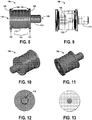
- Figures 8-13 illustrate additional views of another example of the target 106 having a different dimension, according to an example embodiment.
- Figure 8 illustrates a side view of the target 106
- Figure 9 illustrates a wireframe side view of the target 106
- Figure 10 illustrates an isometric view of the target 106 from a bottom perspective
- Figure 11 illustrates an isometric view of the target 106 from a top perspective
- Figure 12 illustrates a top view of the target 106
- Figure 13 illustrates a bottom view of the target 106.
- Figures 14-19 illustrate additional views of yet another example of the target 106, according to an example embodiment.
- Figure 14 illustrates a side view of the target 106
- Figure 15 illustrates a wireframe side view of the target 106
- Figure 16 illustrates an isometric view of the target 106 from a bottom perspective
- Figure 17 illustrates an isometric view of the target 106 from a top perspective
- Figure 18 illustrates a top view of the target 106
- Figure 19 illustrates a bottom view of the target 106.
- the target 106 can be sized as needed for an application, and the shaft 114 is then dimensioned for receipt into the hole 102.
- the target 106 may be about an inch in length, or within a range of about 0.5 to about 5 inches depending on an application or use.
- the size of the target 106 can be made smaller or larger, however, depending on desired uses, and these ranges are given as examples only.
- the shaft 114 has a circumference smaller than a circumference of the cylinder body 112.
- the shaft 114 can be configured to have a larger circumference than the circumference of the cylinder body 112.
- the target 106 can be configured or manufactured to comprise a material of that of the workpiece 104 into which the target 106 is inserted to enable high quality scanning.
- an outer surface of the cylinder body 112 of the target 106 includes a non-reflective coating such that light from the scanner is not reflected back.
- Example materials that can be used for the target 106 include steel, zinc-phosphate, titanium, and aluminum. All components of the target 106 can be comprised of the same material.
- the target 106 is used as a fiducial for generating location information pertaining to the hole 102.
- the scanner 108 provides a light pattern and generates a surface scan of everything in a field of view from the camera(s) 121, and builds a 3D surface from received data. Using data from the surface scan, the target 106 can be identified to generate a feature location.
- the scanner 108 provides a light pattern on surfaces of the target 106 and the workpiece 104, and generates the data points (e.g., point cloud) as representative of the components.
- the target 106 having a cylindrical shape, provides an increased scanning area to allow the scanner 108 to establish a centerline even if the target 106 is partially obstructed (as compared to using a flat circular target, for example). Further, the target 106 with the cylindrical shape is useable in any rotational orientation.
- Figure 20 illustrates an example of data points of the target 106 generated by the scanner 108, according to an example embodiment.
- the increased scanning area of the target 106 enables increased data points to be generated to interpolate the centerline of the hole 116.
- the "+" indicate various points on a surface of the cylinder body 112 at which data points are generated.
- many data points can be generated, such as in a range of a few hundred or more (e.g., 600 data points). By using a larger number of data points, uncertainty in determination of the vector of the hole 102 is reduced.
- the cylinder body 112 provides a surface to generate data points, and the processor(s) 110 interpolate the longitudinal axis 118 of the cylinder body 112 based on fitting the plurality of data points to a cylindrical shape.
- the longitudinal axis 118 of the cylinder body 112 extends longitudinally along the target 102.
- Geometric shape fitting can be used to fit the received data points to a known model of a cylindrical shape.
- Figure 21 illustrates an example diagram to determine a position of the hole 102, according to an example embodiment.
- the processor(s) 110 determine the position of the hole 102 by determining an intersection of the longitudinal axis 118 of the cylinder body 112 and a plane 162 of a surface of the workpiece 104.
- the processor(s) 110 determine the position and the vector of the hole 102 based on an intersection of the centerline or longitudinal line 118 of the cylinder body 112 aligns with the centerline 140 of the shaft 114. In other examples, the processor(s) 110 determine the vector of the hole 102 by determining the longitudinal axis 118 of the cylinder body 112 based on the plurality of data points, and the vector of the hole 102 matches the longitudinal axis 118.
- Figure 22 illustrates an example of the hole 102 in the workpiece 104 formed such that a vector 164 is determined, according to an example embodiment. The vector 164 is not normal to the plane 162 of the surface of the workpiece 104, which may be an assumed orientation of the vector. Thus, use of the target 106 enables determination of the vector 164 in an accurate manner.
- Figure 23 illustrates an example of a 3D model, generated by the processor(s) 110 of at least a portion of the workpiece 104 using the position of the hole 102 and the vector of the hole formed in the workpiece 104, according to an example embodiment. Also shown are models of the target 106 inserted into holes.
- Figure 24 illustrates an example of using multiple targets, according to an example embodiment.
- a single-point target 166 is inserted into the cavity 156 of the cylinder body 112 of the target 106, and the processor(s) 110 receive data representative of the single-point target 166 and determine a position of the target 106 based on the data representative of the single-point target 166.
- the single-point target 166 can be useful to filter surface data based on a single point of data seen from an end viewpoint.
- the lower accuracy single point target 166 can be used to find the high accuracy cylindrical target 106.
- Figure 25 shows a flowchart of an example method 200 for determining a position and a vector of the hole 102 formed in the workpiece 104 based on scanned data of the workpiece 104, according to an example embodiment.
- Method 200 shown in Figure 25 presents an embodiment of a method that could be used or performed by the system 100 or components of the system 100, shown in Figure 1 , for example.
- devices or systems may be used or configured to perform logical functions presented in Figure 25 .
- components of the devices and/or systems may be configured to perform the functions such that the components are actually configured and structured (with hardware and/or software) to enable such performance.
- Method 200 may include one or more operations, functions, or actions as illustrated by one or more of blocks 202-210. Also, the various blocks may be combined into fewer blocks, divided into additional blocks, and/or removed based upon the desired implementation.
- the method 200 includes causing the scanner 108 to scan the target 106 that is inserted into the hole 102 formed in the workpiece 104.
- the target 106 includes the shaft 114 coupled to the hole 102 in the workpiece 104 and the target 106 comprises the cylinder body 112 extending from the shaft 114.
- the shaft 114 couples to the hole 102 and the cylinder body 112 extends from the hole 102 such that the centerline 116 of the hole 102 is collinear with the longitudinal axis 118 of the cylinder body 112.
- the processor(s) 110 may send instructions to the scanner 108 to scan the target 106 and workpiece 104.
- the method 200 includes receiving scan data, from the scanner 108, including a plurality of data points representative of a surface area of the cylinder body 112 of the target 106 and data points representative of a surrounding workpiece 104.
- the method 200 includes interpolating, by the processor(s) 110, the longitudinal axis 118 of the cylinder body 112 based on fitting the plurality of data points representative of the surface area of the cylinder body 112 to a cylindrical shape, and the longitudinal axis 118 of the cylinder body 112 extends longitudinally along the target 106.
- the method 200 includes determining, by the processor(s) 110, a position of the hole 102 and a vector of the hole 102 formed in the workpiece 104 based on an intersection of the longitudinal axis 118 of the cylinder body 112 and the plane 162 of a surface of the workpiece 104.
- the method 200 includes generating, by the processor(s) 110, a three-dimensional (3D) model of at least a portion of the workpiece 104 using the position of the hole 102 and the vector of the hole 102 formed in the workpiece 104.
- the 3D model may be generated using the point cloud data received from the scanner 108.
- Figure 26 shows a flowchart of an example method for use with the method 200 shown in Figure 25 , according to an example embodiment.
- additional functions include scanning the target 106 and the surrounding workpiece 104 in any rotational orientation to generate the plurality of data points representative of the surface area of the cylinder body 112.
- the vector of the hole 102 can be established by scanning from any sides due to the target 106 having a cylindrical shape and body.
- Figure 27 shows a flowchart of another example method for use with the method 200 shown in Figure 25 , according to an example embodiment.
- additional functions include determining a virtual assembly of the workpiece 104 with a component based on the 3D model of the workpiece 104 and a 3D model of the component, and at block 218, determining a position of at least one hole to create in the component based on alignment of the 3D model of the workpiece 104 and the 3D model of the component and the position of the hole 102 formed in the workpiece 104.
- the hole to be created in the component is determined to line up with the position of the hole 102 formed in the workpiece 104.
- a 3D model of individual components are created. Once a hole location is known or determined for one component, a determination of where to place holes in other components can be made so as to virtually assemble the components together. The components can be virtually assembled prior to an actual build process, and verification of the design configurations can be made.
- Figure 28 shows a flowchart of another example method for use with the method 200 shown in Figure 25 , according to an example embodiment.
- the single-point target 166 is inserted into the cavity 156 of the cylinder body 112 of the target 106, and additional functions include receiving data representative of the single-point target 166 at block 220, and determining a position of the target 106 based on the data representative of the single-point target 166, at block 222.
- Example methods and systems described can improve system accuracy and usability of high accuracy systems so as to reduce build time, and increase production efficiency.
Landscapes
- Engineering & Computer Science (AREA)
- General Physics & Mathematics (AREA)
- Physics & Mathematics (AREA)
- Computer Vision & Pattern Recognition (AREA)
- Theoretical Computer Science (AREA)
- Automation & Control Theory (AREA)
- Manufacturing & Machinery (AREA)
- Health & Medical Sciences (AREA)
- Artificial Intelligence (AREA)
- Evolutionary Computation (AREA)
- Medical Informatics (AREA)
- Software Systems (AREA)
- Human Computer Interaction (AREA)
- Quality & Reliability (AREA)
- Length Measuring Devices By Optical Means (AREA)
- Machine Tool Sensing Apparatuses (AREA)
Abstract
Description
- The present disclosure relates generally to three-dimensional (3D) modeling of workpiece components, and more particularly to, a surface based target for insertion into a hole formed in a workpiece enabling highly accurate determination of a position of the hole and a vector of the hole within scanned data of the workpiece.
- During manufacture of items that include an assembly of components or workpieces, often a three-dimensional (3D) model of each component is generated, and then the components are virtually assembled using the 3D models to assess the manufactured item prior to actually building the item.
- A 3D model of a component may be generated using a structured light scanner to scan the component. When the component includes a hole, such as a drilled hole for attaching a fitting for example, a target is generally attached or coupled to the hole during the scanning process to enable identification of a location or position of the hole within the scanned data as well as determination of a hole vector. The position of the hole may be necessary to enable virtual assembly of the components that are scanned separately so that the components are lined up by the holes for coupling.
- Existing photogrammetry targets for use in determining hole position and hole vectors can create some uncertainty in hole position due to the fact that the targets generally use only one to two scanned points to generate a vector. For instance, with a single-point target, projection of a location of the scanned single point target can offer error if the hole is not normal to the local surface due to only one scanned data point. With two-point targets, the use of two scanned points to generate a line to define a centerline of the target for the vector hole position is possible, but this can lead to error in a predicted surface position and direction of the hole to the extent that one of the points becomes blocked or shadowed. In addition, with either the single or two point target, the target should be properly oriented relative to the scanner, otherwise, the scanner may introduce some inaccuracies in the vector calculation.
- Using a structured light scanner to scan a component without use of a target can be performed to try to find a position of a hole, but determination of the hole position and hole vector would be difficult and lack high accuracy due to unknown direction and/or orientation of the hole. Other factors that may affect the difficulty include that the structured light scanner may not detect reflective surfaces that typically remain after machining holes when the components are metal, and for holes of a smaller size it can be difficult to capture enough interior surface data to compute an accurate hole position and hole vector.
- What is needed is a scanning target for use with surface scanners, such as structured light scanners, that enables determination of the position and vector of holes within components to a high degree of accuracy.
- In one example, a system is described for determining a position and a vector of a hole formed in a workpiece based on scanned data of the workpiece. The system comprises a target for coupling to the hole formed in the workpiece, and target comprises a cylinder body extending from a shaft. The shaft couples to the hole and the cylinder body extends from the hole such that a centerline of the hole is collinear with a longitudinal axis of the cylinder body. The system also comprises a scanner for projecting a light pattern onto the target and surrounding workpiece and for generating a plurality of data points representative of a surface area of the cylinder body. The system also comprises a processor for receiving the plurality of data points representative of the surface area of the cylinder body generated by the scanner and generating a three-dimensional (3D) model of at least a portion of the workpiece. The processor determines a position of the hole and a vector of the hole formed in the workpiece for the 3D model based on the plurality of data points representative of the surface area of the cylinder body.
- In another example, a target is described for coupling to a hole formed in a workpiece and for use with a scanner in determining a position and a vector of the hole in scanned data. The target comprises a shaft for coupling to the hole and having a centerline extending longitudinally along the shaft, and the shaft couples to the hole such that a centerline of the hole is collinear with the centerline of the shaft. The target also comprises a cylinder body extending from the shaft such that a centerline of the cylinder body aligns with the centerline of the shaft, and the cylinder body includes two parallel circular faces having volume therebetween. The cylinder body includes a cavity, and the centerline of the cylinder body extends longitudinally along the cylinder body between the two parallel circular faces. The position and the vector of the hole is based on an intersection of the centerline of the cylinder body with the centerline of the shaft. The target also comprises a first ring structure coupled to an end of the cylinder body and including an undercut on a portion connected to the cylinder body, and a second ring structure positioned between the cylinder body and the shaft, and including an undercut on a portion connected to the cylinder body.
- In another example, a method is described for determining a position and a vector of a hole formed in a workpiece based on scanned data of the workpiece. The method comprises causing a scanner to scan a target that is inserted into a hole formed in the workpiece, and the target includes a shaft coupled to the hole in the workpiece and the target comprises a cylinder body extending from the shaft. The shaft couples to the hole and the cylinder body extends from the hole such that a centerline of the hole is collinear with a longitudinal axis of the cylinder body. The method also comprises receiving scan data, from the scanner, including a plurality of data points representative of a surface area of the cylinder body of the target and data points representative of a surrounding workpiece, and interpolating, by a processor, the longitudinal axis of the cylinder body based on fitting the plurality of data points representative of the surface area of the cylinder body to a cylindrical shape. The longitudinal axis of the cylinder body extends longitudinally along the target. The method also comprises determining, by the processor, a position of the hole and a vector of the hole formed in the workpiece based on an intersection of the longitudinal axis of the cylinder body and a plane of a surface of the workpiece, and generating, by the processor, a three-dimensional (3D) model of at least a portion of the workpiece using the position of the hole and the vector of the hole formed in the workpiece.
- The features, functions, and advantages that have been discussed can be achieved independently in various embodiments or may be combined in yet other embodiments further details of which can be seen with reference to the following description and drawings.
- The novel features believed characteristic of the illustrative embodiments are set forth in the appended claims. The illustrative embodiments, however, as well as a preferred mode of use, further objectives and descriptions thereof, will best be understood by reference to the following detailed description of an illustrative embodiment of the present disclosure when read in conjunction with the accompanying drawings, wherein:
-
Figure 1 illustrates an example system for determining a position and a vector of a hole formed in a workpiece based on scanned data of the workpiece. -
Figure 2 illustrates a side view of the target, according to an example embodiment. -
Figure 3 illustrates a wireframe side view of the target, according to an example embodiment. -
Figure 4 illustrates an isometric view of the target from a bottom perspective, according to an example embodiment. -
Figure 5 illustrates an isometric view of the target from a top perspective, according to an example embodiment. -
Figure 6 illustrates a top view of the target, according to an example embodiment. -
Figure 7 illustrates a bottom view of the target, according to an example embodiment. -
Figure 8 illustrates a side view of an additional example of the target, according to an example embodiment. -
Figure 9 illustrates a wireframe side view of the additional example of the target, according to an example embodiment. -
Figure 10 illustrates an isometric view of the additional example of the target from a bottom perspective, according to an example embodiment. -
Figure 11 illustrates an isometric view of the additional example of the target from a top perspective, according to an example embodiment. -
Figure 12 illustrates a top view of the additional example of the target, according to an example embodiment. -
Figure 13 illustrates a bottom view of the additional example of the target, according to an example embodiment. -
Figure 14 illustrates a side view of yet another example of the target, according to an example embodiment. -
Figure 15 illustrates a wireframe side view of the other example of the target, according to an example embodiment. -
Figure 16 illustrates an isometric view of the other example of the target from a bottom perspective, according to an example embodiment. -
Figure 17 illustrates an isometric view of the other example of the target from a top perspective, according to an example embodiment. -
Figure 18 illustrates a top view of the other example of the target, according to an example embodiment. -
Figure 19 illustrates a bottom view of the other example of the target, according to an example embodiment. -
Figure 20 illustrates an example of data points of the target generated by the scanner, according to an example embodiment. -
Figure 21 illustrates an example diagram to determine a position of the hole, according to an example embodiment. -
Figure 22 illustrates an example of the hole in the workpiece formed such that a vector is determined, according to an example embodiment. -
Figure 23 illustrates an example of a 3D model, generated by the processor(s) of at least a portion of the workpiece using the position of the hole and the vector of the hole formed in the workpiece, according to an example embodiment. -
Figure 24 illustrates an example of using multiple targets, according to an example embodiment. -
Figure 25 shows a flowchart of an example method for determining a position and a vector of the hole formed in the workpiece based on scanned data of the workpiece, according to an example embodiment. -
Figure 26 shows a flowchart of an example method for use with the method shown inFigure 25 , according to an example embodiment. -
Figure 27 shows a flowchart of another example method for use with the method shown inFigure 25 , according to an example embodiment. -
Figure 28 shows a flowchart of another example method for use with the method shown inFigure 25 , according to an example embodiment. - Disclosed embodiments will now be described more fully hereinafter with reference to the accompanying drawings, in which some, but not all of the disclosed embodiments are shown. Indeed, several different embodiments may be described and should not be construed as limited to the embodiments set forth herein. Rather, these embodiments are described so that this disclosure will be thorough and complete and will fully convey the scope of the disclosure to those skilled in the art.
- In examples described below, a target is used as a fiducial for generating location information pertaining to a hole formed in a workpiece. A scanner provides a light pattern and generates a surface scan of everything in a field of view from camera(s), and a 3D surface is generated from received data. Using data from the surface scan, the target can be identified to generate a feature location.
- Methods and systems for determining a position and a vector of a hole formed in a workpiece based on scanned data of the workpiece are described using the target. An example system includes the target for coupling to the hole formed in the workpiece, a scanner for projecting a light pattern onto the target and surrounding workpiece and for generating a plurality of data points representative of a surface area of a cylinder body of the target, and a processor for receiving the plurality of data points generated by the scanner and generating a three-dimensional (3D) model of at least a portion of the workpiece. The processor determines a position and a vector of the hole formed in the workpiece for the 3D model based on the plurality of data points representative of the surface area of the cylinder body.
- Referring now to the figures,
Figure 1 illustrates anexample system 100 for determining a position and a vector of ahole 102 formed in aworkpiece 104 based on scanned data of theworkpiece 104. Thesystem 100 includes atarget 106 for coupling to thehole 102 formed in theworkpiece 104, ascanner 108 for projecting a light pattern onto thetarget 106 and surroundingworkpiece 104, and one or more processor(s) 110 for receiving data from thescanner 108 and generating a three-dimensional (3D) model of at least a portion of theworkpiece 104. - Within examples, the
target 106 is used to determine the location and vector of thehole 102 drilled in theworkpiece 104. The location and vector of thehole 102 is useful to determine the 3D model of theworkpiece 104, and the 3D model can be used to virtually assembly parts that are scanned separately, for example. - The
target 106 includes acylinder body 112 extending from ashaft 114, and theshaft 114 couples to thehole 102 with thecylinder body 112 extending from thehole 102 such that acenterline 116 of thehole 102 is collinear with alongitudinal axis 118 of thecylinder body 112. Thetarget 106 is inserted into theworkpiece 104 to extend from thehole 102 outward with respect to a surface of theworkpiece 104. - The
cylinder body 112 of thetarget 106 provides an increased surface area to determine thelongitudinal axis 118 that is collinear to thecenterline 116 of thehole 102. Some standard vector targets may create uncertainty in location due to the fact that standard targets generally use only two points to generate a vector. However, example targets described herein using thecylinder body 112 enable use of many points to generate a vector. - The
scanner 108 includes alight source 120 to generate the light pattern onto thetarget 106, and one or more camera(s) to capture images of theworkpiece 104 and/or reflected light. In one example, thescanner 108 is a non-contact structure light scanner that measures many points per scan. Example scanners include an ATOS structured light scanner, or other surface scanners, and 3D scanners. - The
light source 120 can include a single light emitting diode (LED), or multiple LEDs, for example. In addition, thescanner 108 can include many camera(s) 121, such as three cameras to capture a multi-view of theworkpiece 104. Thescanner 108 generates a plurality of data points representative of a surface area of thecylinder body 112. The plurality of data points may include a 3D point cloud of theworkpiece 104 with thetarget 106 inserted. - The processor(s) 110 receive the plurality of data points representative of the surface area of the
cylinder body 112 generated by thescanner 108 and generate the 3D model of at least a portion of theworkpiece 104. The processor(s) 110 determine a position of thehole 102 and a vector of thehole 102 formed in theworkpiece 104 for the 3D model based on the plurality of data points representative of the surface area of thecylinder body 112. - The
system 100 is shown to include acomputing device 122 that has the processor(s) 110, and also acommunication interface 124,data storage 126, anoutput interface 128, and adisplay 130 each connected to acommunication bus 132. Thecomputing device 122 may also include hardware to enable communication within thecomputing device 122 and between thecomputing device 122 and other devices (not shown). The hardware may include transmitters, receivers, and antennas, for example. - In some examples, the
computing device 122 and thescanner 108 may be combined as a single device. - The
communication interface 124 may be a wireless interface and/or one or more wireline interfaces that allow for both short-range communication and long-range communication to one or more networks or to one or more remote devices. Such wireless interfaces may provide for communication under one or more wireless communication protocols, such as Bluetooth, WiFi (e.g., an institute of electrical and electronic engineers (IEEE) 802.11 protocol), Long-Term Evolution (LTE), cellular communications, near-field communication (NFC), and/or other wireless communication protocols. Such wireline interfaces may include Ethernet interface, a Universal Serial Bus (USB) interface, or similar interface to communicate via a wire, a twisted pair of wires, a coaxial cable, an optical link, a fiber-optic link, or other physical connection to a wireline network. Thus, thecommunication interface 124 may be configured to receive input data from one or more devices, such as thescanner 108, and may also be configured to send output data to other devices. - The
data storage 126 may include or take the form of one or more computer-readable storage media that can be read or accessed by the processor(s) 110. The computer-readable storage media can include volatile and/or non-volatile storage components, such as optical, magnetic, organic or other memory or disc storage, which can be integrated in whole or in part with the processor(s) 110. Thedata storage 126 is considered non-transitory computer readable media. In some embodiments, thedata storage 126 can be implemented using a single physical device (e.g., one optical, magnetic, organic or other memory or disc storage unit), while in other embodiments, thedata storage 126 can be implemented using two or more physical devices. - The
data storage 126 thus is a non-transitory computer readable storage medium, andexecutable instructions 134 are stored thereon. Theinstructions 134 include computer executable code. When theinstructions 134 are executed by the processor(s) 110, the processor(s) 110 are caused to perform functions. Such functions include causing thescanner 108 to scan thetarget 106 that is inserted into thehole 102 formed in theworkpiece 104, receiving scan data from thescanner 108, interpolating thelongitudinal axis 118 of thecylinder body 112 based on fitting the scanned data to a cylindrical shape, determining a position of thehole 102 and a vector of thehole 102 formed in theworkpiece 104 based on an intersection of thelongitudinal axis 118 of thecylinder body 112 and a plane of a surface of theworkpiece 104, and generating the 3D model of at least a portion of theworkpiece 104 using the position of thehole 102 and the vector of thehole 102 formed in theworkpiece 104. Additional details of such functions are described more fully below. - The processor(s) 110 may be a general-purpose processor or a special purpose processor (e.g., digital signal processors, application specific integrated circuits, etc.). The processor(s) 110 may receive inputs from the
scanner 108, and process the inputs to generate outputs that are stored in thedata storage 126 and output to thedisplay 130. For example, the data points 136 received from thescanner 108 and the3D model 138 generated by the processor(s) 110 may be stored in thedata storage 126. The processor(s) 110 can be configured to execute the executable instructions 134 (e.g., computer-readable program instructions) that are stored in thedata storage 126 and are executable to provide the functionality of thesystem 100 described herein. - The
output interface 128 outputs information to thedisplay 130 or to other components as well. Thus, theoutput interface 128 may be similar to thecommunication interface 124 and can be a wireless interface (e.g., transmitter) or a wired interface as well. -
Figures 2-7 illustrate example views of thetarget 106, according to an example embodiment.Figure 2 illustrates a side view of thetarget 106,Figure 3 illustrates a wireframe side view of thetarget 106,Figure 4 illustrates an isometric view of thetarget 106 from a bottom perspective,Figure 5 illustrates an isometric view of thetarget 106 from a top perspective,Figure 6 illustrates a top view of thetarget 106, andFigure 7 illustrates a bottom view of thetarget 106. -
Figure 2 illustrates theshaft 114 having acenterline 140 extending longitudinally along theshaft 114, and the shaft couples to thehole 102 such that thecenterline 116 of thehole 102 is collinear with thecenterline 140 of theshaft 114. Thecylinder body 112 extends from theshaft 114 such that thecenterline 118 of thecylinder body 112 aligns with thecenterline 140 of theshaft 114, and thecenterline 118 of thecylinder body 112 extends longitudinally along thecylinder body 112 between two parallel circular faces 142 and 144. Thus, thecylinder body 112 is a full cylinder body including the two parallel circular faces 142 and 144 havingvolume 146 therebetween. - The
target 106 also includes afirst ring structure 148 coupled to an end of thecylinder body 112 and including an undercut 150 on a portion connected to thecylinder body 112, and asecond ring structure 152 positioned between thecylinder body 112 and theshaft 114 and including an undercut 154 on a portion connected to thecylinder body 112. Thefirst ring structure 148 and thesecond ring structure 152 protect surfaces of thetarget 106, and can have flared edges or raised features, or be wider or shorter depending on an application or use of thetarget 106. -
Figure 3 illustrates that thetarget 106 includes acavity 156 within thecylinder body 112. Thecavity 156 is an opening that is shown to extend fully through a center of thetarget 106. However, in other examples, thecavity 156 may not extend fully through thetarget 106, such as shown, for example, inFigure 15 . -
Figure 4 illustrates that an end of thetarget 106 includes anopening 158 to thecavity 156.Figure 5 illustrates that theshaft 114 may also include anopening 160 in an example in which thecavity 156 extends fully through thetarget 106. -
Figure 6 illustrates a top view of thetarget 106 showing theopening 160 in theshaft 114. In examples where thecavity 156 does not extend fully through thetarget 106, theshaft 114 may not include theopening 160, such as for example, shown inFigure 18 .Figure 7 illustrates a bottom view of thetarget 106 showing theopening 158 in the end of thecylinder body 112. -
Figures 8-13 illustrate additional views of another example of thetarget 106 having a different dimension, according to an example embodiment.Figure 8 illustrates a side view of thetarget 106,Figure 9 illustrates a wireframe side view of thetarget 106,Figure 10 illustrates an isometric view of thetarget 106 from a bottom perspective,Figure 11 illustrates an isometric view of thetarget 106 from a top perspective,Figure 12 illustrates a top view of thetarget 106, andFigure 13 illustrates a bottom view of thetarget 106. -
Figures 14-19 illustrate additional views of yet another example of thetarget 106, according to an example embodiment.Figure 14 illustrates a side view of thetarget 106,Figure 15 illustrates a wireframe side view of thetarget 106,Figure 16 illustrates an isometric view of thetarget 106 from a bottom perspective,Figure 17 illustrates an isometric view of thetarget 106 from a top perspective,Figure 18 illustrates a top view of thetarget 106, andFigure 19 illustrates a bottom view of thetarget 106. - The
target 106 can be sized as needed for an application, and theshaft 114 is then dimensioned for receipt into thehole 102. As some examples, thetarget 106 may be about an inch in length, or within a range of about 0.5 to about 5 inches depending on an application or use. The size of thetarget 106 can be made smaller or larger, however, depending on desired uses, and these ranges are given as examples only. As shown in the figures, theshaft 114 has a circumference smaller than a circumference of thecylinder body 112. For larger holes, in some examples, theshaft 114 can be configured to have a larger circumference than the circumference of thecylinder body 112. - The
target 106 can be configured or manufactured to comprise a material of that of theworkpiece 104 into which thetarget 106 is inserted to enable high quality scanning. In some examples, an outer surface of thecylinder body 112 of thetarget 106 includes a non-reflective coating such that light from the scanner is not reflected back. Example materials that can be used for thetarget 106 include steel, zinc-phosphate, titanium, and aluminum. All components of thetarget 106 can be comprised of the same material. - In operation, the
target 106 is used as a fiducial for generating location information pertaining to thehole 102. Thescanner 108 provides a light pattern and generates a surface scan of everything in a field of view from the camera(s) 121, and builds a 3D surface from received data. Using data from the surface scan, thetarget 106 can be identified to generate a feature location. - In operation, the
scanner 108 provides a light pattern on surfaces of thetarget 106 and theworkpiece 104, and generates the data points (e.g., point cloud) as representative of the components. Thetarget 106, having a cylindrical shape, provides an increased scanning area to allow thescanner 108 to establish a centerline even if thetarget 106 is partially obstructed (as compared to using a flat circular target, for example). Further, thetarget 106 with the cylindrical shape is useable in any rotational orientation. -
Figure 20 illustrates an example of data points of thetarget 106 generated by thescanner 108, according to an example embodiment. The increased scanning area of thetarget 106 enables increased data points to be generated to interpolate the centerline of thehole 116. As an example shown inFigure 20 , the "+" indicate various points on a surface of thecylinder body 112 at which data points are generated. In some examples, many data points can be generated, such as in a range of a few hundred or more (e.g., 600 data points). By using a larger number of data points, uncertainty in determination of the vector of thehole 102 is reduced. - The
cylinder body 112 provides a surface to generate data points, and the processor(s) 110 interpolate thelongitudinal axis 118 of thecylinder body 112 based on fitting the plurality of data points to a cylindrical shape. Thelongitudinal axis 118 of thecylinder body 112 extends longitudinally along thetarget 102. Geometric shape fitting can be used to fit the received data points to a known model of a cylindrical shape. -
Figure 21 illustrates an example diagram to determine a position of thehole 102, according to an example embodiment. Once the model of thetarget 106 is determined, the processor(s) 110 determine the position of thehole 102 by determining an intersection of thelongitudinal axis 118 of thecylinder body 112 and aplane 162 of a surface of theworkpiece 104. - In some examples, the processor(s) 110 determine the position and the vector of the
hole 102 based on an intersection of the centerline orlongitudinal line 118 of thecylinder body 112 aligns with thecenterline 140 of theshaft 114. In other examples, the processor(s) 110 determine the vector of thehole 102 by determining thelongitudinal axis 118 of thecylinder body 112 based on the plurality of data points, and the vector of thehole 102 matches thelongitudinal axis 118.Figure 22 illustrates an example of thehole 102 in theworkpiece 104 formed such that avector 164 is determined, according to an example embodiment. Thevector 164 is not normal to theplane 162 of the surface of theworkpiece 104, which may be an assumed orientation of the vector. Thus, use of thetarget 106 enables determination of thevector 164 in an accurate manner. -
Figure 23 illustrates an example of a 3D model, generated by the processor(s) 110 of at least a portion of theworkpiece 104 using the position of thehole 102 and the vector of the hole formed in theworkpiece 104, according to an example embodiment. Also shown are models of thetarget 106 inserted into holes. - Within some examples, it can be useful to use multiple targets to pinpoint a location of the
hole 102.Figure 24 illustrates an example of using multiple targets, according to an example embodiment. InFigure 24 , a single-point target 166 is inserted into thecavity 156 of thecylinder body 112 of thetarget 106, and the processor(s) 110 receive data representative of the single-point target 166 and determine a position of thetarget 106 based on the data representative of the single-point target 166. The single-point target 166 can be useful to filter surface data based on a single point of data seen from an end viewpoint. The lower accuracysingle point target 166 can be used to find the high accuracycylindrical target 106. -
Figure 25 shows a flowchart of anexample method 200 for determining a position and a vector of thehole 102 formed in theworkpiece 104 based on scanned data of theworkpiece 104, according to an example embodiment.Method 200 shown inFigure 25 presents an embodiment of a method that could be used or performed by thesystem 100 or components of thesystem 100, shown inFigure 1 , for example. Further, devices or systems may be used or configured to perform logical functions presented inFigure 25 . In some instances, components of the devices and/or systems may be configured to perform the functions such that the components are actually configured and structured (with hardware and/or software) to enable such performance. In other examples, components of the devices and/or systems may be arranged to be adapted to, capable of, or suited for performing the functions, such as when operated in a specific manner.Method 200 may include one or more operations, functions, or actions as illustrated by one or more of blocks 202-210. Also, the various blocks may be combined into fewer blocks, divided into additional blocks, and/or removed based upon the desired implementation. - It should be understood that for this and other processes and methods disclosed herein, flowcharts show functionality and operation of one possible implementation of present embodiments. Alternative implementations are included within the scope of the example embodiments of the present disclosure in which functions may be executed out of order from that shown or discussed, including substantially concurrent or in reverse order, depending on the functionality involved, as would be understood by those reasonably skilled in the art.
- At
block 202, themethod 200 includes causing thescanner 108 to scan thetarget 106 that is inserted into thehole 102 formed in theworkpiece 104. As described, thetarget 106 includes theshaft 114 coupled to thehole 102 in theworkpiece 104 and thetarget 106 comprises thecylinder body 112 extending from theshaft 114. Theshaft 114 couples to thehole 102 and thecylinder body 112 extends from thehole 102 such that thecenterline 116 of thehole 102 is collinear with thelongitudinal axis 118 of thecylinder body 112. The processor(s) 110 may send instructions to thescanner 108 to scan thetarget 106 andworkpiece 104. - At
block 204, themethod 200 includes receiving scan data, from thescanner 108, including a plurality of data points representative of a surface area of thecylinder body 112 of thetarget 106 and data points representative of asurrounding workpiece 104. - At
block 206, themethod 200 includes interpolating, by the processor(s) 110, thelongitudinal axis 118 of thecylinder body 112 based on fitting the plurality of data points representative of the surface area of thecylinder body 112 to a cylindrical shape, and thelongitudinal axis 118 of thecylinder body 112 extends longitudinally along thetarget 106. - At
block 208, themethod 200 includes determining, by the processor(s) 110, a position of thehole 102 and a vector of thehole 102 formed in theworkpiece 104 based on an intersection of thelongitudinal axis 118 of thecylinder body 112 and theplane 162 of a surface of theworkpiece 104. - At
block 210, themethod 200 includes generating, by the processor(s) 110, a three-dimensional (3D) model of at least a portion of theworkpiece 104 using the position of thehole 102 and the vector of thehole 102 formed in theworkpiece 104. The 3D model may be generated using the point cloud data received from thescanner 108. -
Figure 26 shows a flowchart of an example method for use with themethod 200 shown inFigure 25 , according to an example embodiment. Atblock 212, additional functions include scanning thetarget 106 and the surroundingworkpiece 104 in any rotational orientation to generate the plurality of data points representative of the surface area of thecylinder body 112. In this example, the vector of thehole 102 can be established by scanning from any sides due to thetarget 106 having a cylindrical shape and body. -
Figure 27 shows a flowchart of another example method for use with themethod 200 shown inFigure 25 , according to an example embodiment. Atblock 216, additional functions include determining a virtual assembly of theworkpiece 104 with a component based on the 3D model of theworkpiece 104 and a 3D model of the component, and atblock 218, determining a position of at least one hole to create in the component based on alignment of the 3D model of theworkpiece 104 and the 3D model of the component and the position of thehole 102 formed in theworkpiece 104. In this example, the hole to be created in the component is determined to line up with the position of thehole 102 formed in theworkpiece 104. - In this example, because components are generally scanned separately, a 3D model of individual components are created. Once a hole location is known or determined for one component, a determination of where to place holes in other components can be made so as to virtually assemble the components together. The components can be virtually assembled prior to an actual build process, and verification of the design configurations can be made.
-
Figure 28 shows a flowchart of another example method for use with themethod 200 shown inFigure 25 , according to an example embodiment. In this example, the single-point target 166 is inserted into thecavity 156 of thecylinder body 112 of thetarget 106, and additional functions include receiving data representative of the single-point target 166 atblock 220, and determining a position of thetarget 106 based on the data representative of the single-point target 166, atblock 222.
Example methods and systems described can improve system accuracy and usability of high accuracy systems so as to reduce build time, and increase production efficiency. - Further, the disclosure comprises embodiments according to the following clauses:
- Clause 1. A system for determining a position and a vector of a hole formed in a workpiece based on scanned data of the workpiece, the system comprising:
- a target for coupling to the hole formed in the workpiece, the target comprising a cylinder body extending from a shaft, wherein the shaft couples to the hole and the cylinder body extends from the hole such that a centerline of the hole is collinear with a longitudinal axis of the cylinder body;
- scanner for projecting a light pattern onto the target and surrounding workpiece and for generating a plurality of data points representative of a surface area of the cylinder body; and
- a processor for receiving the plurality of data points representative of the surface area of the cylinder body generated by the scanner and generating a three-dimensional (3D) model of at least a portion of the workpiece, the processor determining a position of the hole and a vector of the hole formed in the workpiece for the 3D model based on the plurality of data points representative of the surface area of the cylinder body.
- Clause 2. The system of Clause 1, wherein the cylinder body includes a cavity.
- Clause 3. The system of Clause 1, wherein the cylinder body is a full cylinder body including two parallel circular faces having volume therebetween.
- Clause 4. The system of Clause 1, wherein the shaft is dimensioned for receipt into the hole.
- Clause 5. The system of Clause 1, wherein an outer surface of the cylinder body includes a non-reflective coating.
- Clause 6. The system of Clause 1, wherein the target comprises a material of that of the workpiece into which the target is inserted.
- Clause 7. The system of Clause 1, wherein the target extends from the hole outward with respect to a surface of the workpiece.
- Clause 8. The system of Clause 1, wherein the target further comprises a first ring structure coupled to an end of the cylinder body and a second ring structure between the cylinder body and the shaft.
- Clause 9. The system of Clause 8, wherein the first ring structure and the second ring structure include an undercut on a portion connected to the cylinder body.
- Clause 10. The system of Clause 1, wherein the processor determines the position of the hole by determining an intersection of the longitudinal axis of the cylinder body and a plane of a surface of the workpiece.
- Clause 11. The system of Clause 1, wherein the processor determines the vector of the hole by determining the longitudinal axis of the cylinder body based on the plurality of data points.
- Clause 12. The system of Clause 1, wherein the processor interpolates the longitudinal axis of the cylinder body based on fitting the plurality of data points to a cylindrical shape, wherein the longitudinal axis of the cylinder body extends longitudinally along the target.
- Clause 13. The system of Clause 1, further comprising:
- a single-point target inserted into a cavity of the cylinder body of the target,
- wherein the processor receives data representative of the single-point target and determines a position of the target based on the data representative of the single-point target.
- Clause 14. A target for coupling to a hole formed in a workpiece and for use with a scanner in determining a position and a vector of the hole in scanned data, the target comprising:
- a shaft for coupling to the hole and having a centerline extending longitudinally along the shaft, wherein the shaft couples to the hole such that a centerline of the hole is collinear with the centerline of the shaft;
- a cylinder body extending from the shaft such that a centerline of the cylinder body aligns with the centerline of the shaft, wherein the cylinder body includes two parallel circular faces having volume therebetween, and wherein the cylinder body includes a cavity, and wherein the centerline of the cylinder body extends longitudinally along the cylinder body between the two parallel circular faces, wherein the position and the vector of the hole is based on an intersection of the centerline of the cylinder body with the centerline of the shaft;
- a first ring structure coupled to an end of the cylinder body and including an undercut on a portion connected to the cylinder body; and
- a second ring structure positioned between the cylinder body and the shaft, and including an undercut on a portion connected to the cylinder body.
- Clause 15. The target of Clause 14, wherein an outer surface of the cylinder body includes a non-reflective coating.
- Clause 16. The target of Clause 14, wherein the target comprises a material of that of the workpiece into which the target is inserted.
- Clause 17. A method for determining a position and a vector of a hole formed in a workpiece based on scanned data of the workpiece, the method comprising:
- causing a scanner to scan a target that is inserted into a hole formed in the workpiece, wherein the target includes a shaft coupled to the hole in the workpiece and the target comprises a cylinder body extending from the shaft, wherein the shaft couples to the hole and the cylinder body extends from the hole such that a centerline of the hole is collinear with a longitudinal axis of the cylinder body;
- receiving scan data, from the scanner, including a plurality of data points representative of a surface area of the cylinder body of the target and data points representative of a surrounding workpiece;
- interpolating, by a processor, the longitudinal axis of the cylinder body based on fitting the plurality of data points representative of the surface area of the cylinder body to a cylindrical shape, wherein the longitudinal axis of the cylinder body extends longitudinally along the target;
- determining, by the processor, a position of the hole and a vector of the hole formed in the workpiece based on an intersection of the longitudinal axis of the cylinder body and a plane of a surface of the workpiece; and
- generating, by the processor, a three-dimensional (3D) model of at least a portion of the workpiece using the position of the hole and the vector of the hole formed in the workpiece.
- Clause 18. The method of Clause 17, further comprising:
- scanning the target and the surrounding workpiece in any rotational orientation to generate the plurality of data points representative of the surface area of the cylinder body.
- Clause 19. The method of Clause 17, further comprising:
- determining a virtual assembly of the workpiece with a component based on the 3D model of the workpiece and a 3D model of the component; and
- determining a position of at least one hole to create in the component based on alignment of the 3D model of the workpiece and the 3D model of the component and the position of the hole formed in the workpiece, such that the at least one hole to create in the component lines up with the position of the hole formed in the workpiece.
- Clause 20. The method of Clause 17, wherein a single-point target is inserted into a cavity of the cylinder body of the target, and the method further comprises:
- receiving data representative of the single-point target; and
- determining a position of the target based on the data representative of the single-point target.
- The description of the different advantageous arrangements has been presented for purposes of illustration and description, and is not intended to be exhaustive or limited to the embodiments in the form disclosed. Many modifications and variations will be apparent to those of ordinary skill in the art. Further, different advantageous embodiments may describe different advantages as compared to other advantageous embodiments. The embodiment or embodiments selected are chosen and described in order to best explain the principles of the embodiments, the practical application, and to enable others of ordinary skill in the art to understand the disclosure for various embodiments with various modifications as are suited to the particular use contemplated.
Claims (15)
- A system (100) for determining a position and a vector (164) of a hole (102) formed in a workpiece (104) based on scanned data of the workpiece, the system comprising:a target (106) for coupling to the hole formed in the workpiece, the target comprising a cylinder body (112) extending from a shaft (114), wherein the shaft couples to the hole and the cylinder body extends from the hole such that a centerline (116) of the hole is collinear with a longitudinal axis (118) of the cylinder body;scanner (108) for projecting a light pattern onto the target and surrounding workpiece and for generating a plurality of data points (136) representative of a surface area of the cylinder body; anda processor (110) for receiving the plurality of data points representative of the surface area of the cylinder body generated by the scanner and generating a three-dimensional (3D) model (138) of at least a portion of the workpiece, the processor determining a position of the hole and a vector of the hole formed in the workpiece for the 3D model based on the plurality of data points representative of the surface area of the cylinder body.
- The system (100) of claim 1, wherein the cylinder body (112) includes a cavity (156).
- The system (100) of any of claims 1-2, wherein the cylinder body (112) is a full cylinder body (112) including two parallel circular faces (142, 144) having volume (146) therebetween.
- The system (100) of any of claims 1-3, wherein the shaft (114) is dimensioned for receipt into the hole (102).
- The system (100) of any of claims 1-4, wherein an outer surface of the cylinder body (112) includes a non-reflective coating.
- The system (100) of any of claims 1-5, wherein the target (106) extends from the hole (102) outward with respect to a surface of the workpiece (104).
- The system (100) of any of claims 1-6, wherein the target (106) further comprises a first ring structure (148) coupled to an end of the cylinder body (112) and a second ring structure (152) between the cylinder body and the shaft (114).
- The system (100) of claim 7, wherein the first ring structure (148) and the second ring structure (152) include an undercut (150, 154) on a portion connected to the cylinder body (112).
- The system (100) of any of claims 1-8, wherein the processor (110) determines the position of the hole (102) by determining an intersection of the longitudinal axis (118) of the cylinder body (112) and a plane of a surface of the workpiece (104).
- The system (100) of any of claims 1-9, wherein the processor (110) determines the vector (164) of the hole (102) by determining the longitudinal axis (118) of the cylinder body (112) based on the plurality of data points (136).
- The system (100) of any of claims 1-10, wherein the processor (110) interpolates the longitudinal axis (118) of the cylinder body (112) based on fitting the plurality of data points (136) to a cylindrical shape, wherein the longitudinal axis (118) of the cylinder body extends longitudinally along the target (106).
- A method (300) for determining a position and a vector (164) of a hole (102) formed in a workpiece (104) based on scanned data of the workpiece, the method comprising:causing (202) a scanner (108) to scan a target (106) that is inserted into a hole formed in the workpiece, wherein the target includes a shaft (114) coupled to the hole in the workpiece and the target comprises a cylinder body (112) extending from the shaft, wherein the shaft couples to the hole and the cylinder body extends from the hole such that a centerline (116) of the hole is collinear with a longitudinal axis (118) of the cylinder body;receiving (204) scan data, from the scanner, including a plurality of data points (136) representative of a surface area of the cylinder body of the target and data points representative of a surrounding workpiece;interpolating (206), by a processor (110), the longitudinal axis of the cylinder body based on fitting the plurality of data points representative of the surface area of the cylinder body to a cylindrical shape, wherein the longitudinal axis of the cylinder body extends longitudinally along the target;determining (208), by the processor, a position of the hole and a vector of the hole formed in the workpiece based on an intersection of the longitudinal axis of the cylinder body and a plane of a surface of the workpiece; andgenerating (210), by the processor, a three-dimensional (3D) model (138) of at least a portion of the workpiece using the position of the hole and the vector of the hole formed in the workpiece.
- The method (300) of claim 12, further comprising:scanning (212) the target (106) and the surrounding workpiece in any rotational orientation to generate the plurality of data points (136) representative of the surface area of the cylinder body (112).
- The method (300) of any of claims 12-13, further comprising:determining (216) a virtual assembly of the workpiece (104) with a component based on the 3D model (138) of the workpiece and a 3D model of the component; anddetermining (218) a position of at least one hole (102) to create in the component based on alignment of the 3D model of the workpiece and the 3D model of the component and the position of the hole formed in the workpiece, such that the at least one hole to create in the component lines up with the position of the hole formed in the workpiece.
- The method of any of claims 12-14, wherein a single-point target (166) is inserted into a cavity (156) of the cylinder body (112) of the target (106), and the method further comprises:receiving (220) data representative of the single-point target; anddetermining (222) a position of the target based on the data representative of the single-point target.
Applications Claiming Priority (1)
| Application Number | Priority Date | Filing Date | Title |
|---|---|---|---|
| US15/290,190 US10303154B2 (en) | 2016-10-11 | 2016-10-11 | Surface based hole target for use with systems and methods for determining a position and a vector of a hole formed in a workpiece |
Publications (2)
| Publication Number | Publication Date |
|---|---|
| EP3309503A1 true EP3309503A1 (en) | 2018-04-18 |
| EP3309503B1 EP3309503B1 (en) | 2021-12-29 |
Family
ID=59772351
Family Applications (1)
| Application Number | Title | Priority Date | Filing Date |
|---|---|---|---|
| EP17185384.9A Active EP3309503B1 (en) | 2016-10-11 | 2017-08-08 | Surface based hole target for use with systems and methods for determining a position and a vector of a hole formed in a workpiece |
Country Status (4)
| Country | Link |
|---|---|
| US (1) | US10303154B2 (en) |
| EP (1) | EP3309503B1 (en) |
| JP (1) | JP7046533B2 (en) |
| CN (1) | CN107917668B (en) |
Cited By (3)
| Publication number | Priority date | Publication date | Assignee | Title |
|---|---|---|---|---|
| US10303154B2 (en) | 2016-10-11 | 2019-05-28 | The Boeing Company | Surface based hole target for use with systems and methods for determining a position and a vector of a hole formed in a workpiece |
| EP3757507A1 (en) * | 2019-06-28 | 2020-12-30 | The Boeing Company | Hole location targets and measurement systems, and methods for measuring a location of a hole |
| US11248896B2 (en) | 2019-06-28 | 2022-02-15 | The Boeing Company | Hole location targets and measurement systems, and methods for measuring a location of a hole |
Families Citing this family (6)
| Publication number | Priority date | Publication date | Assignee | Title |
|---|---|---|---|---|
| EP3814230B1 (en) * | 2018-06-28 | 2022-10-12 | BAE SYSTEMS plc | Method and system for attaching an aircraft skin to an aircraft airframe |
| PL3972903T3 (en) | 2019-05-23 | 2025-03-03 | Bae Systems Plc | A method and apparatus for producing at least part of a structural frame of a vehicle |
| US11138719B2 (en) * | 2019-12-19 | 2021-10-05 | The Boeing Company | Three-dimensional inspection of a workpiece for conformance to a specification |
| CN111664813B (en) * | 2020-05-15 | 2021-08-03 | 成都飞机工业(集团)有限责任公司 | Free surface arbitrary hole normal vector measuring device and method and compensation method |
| CN114061448A (en) * | 2021-10-26 | 2022-02-18 | 成都飞机工业(集团)有限责任公司 | Method and device for obtaining assembling position deviation of assembling hole of composite material wallboard |
| US12461996B2 (en) * | 2022-09-16 | 2025-11-04 | Ford Global Technologies, Llc | Systems and methods for component detection in a manufacturing environment |
Citations (3)
| Publication number | Priority date | Publication date | Assignee | Title |
|---|---|---|---|---|
| US4791482A (en) * | 1987-02-06 | 1988-12-13 | Westinghouse Electric Corp. | Object locating system |
| WO2002097362A1 (en) * | 2001-05-31 | 2002-12-05 | Bae Systems Plc | Photogrammetry targets |
| US20080123112A1 (en) * | 2006-05-10 | 2008-05-29 | The Boeing Company | Photogrammetric contrasting light for hole recognition |
Family Cites Families (14)
| Publication number | Priority date | Publication date | Assignee | Title |
|---|---|---|---|---|
| JP2000055603A (en) | 1998-08-10 | 2000-02-25 | Aisin Takaoka Ltd | Hole inspecting device |
| US6807742B2 (en) * | 2002-09-06 | 2004-10-26 | Trijicon, Inc. | Reflex sight with multiple power sources for reticle |
| MXPA06014676A (en) * | 2004-06-15 | 2007-06-22 | Tipper Tie Inc | Modular clipping packaging apparatus and associated devices, methods and systems. |
| MXPA06003044A (en) * | 2006-03-17 | 2007-09-17 | Juan Antonio Ferro De La Cruz | Device for aligning modular centres in concrete walls, and alignment method. |
| US8951391B2 (en) * | 2007-02-14 | 2015-02-10 | Miles McClure | Solar distillation device |
| JP4309439B2 (en) | 2007-03-30 | 2009-08-05 | ファナック株式会社 | Object take-out device |
| US8225748B2 (en) * | 2007-12-14 | 2012-07-24 | Robert Jordy Crawford | Potty pole |
| CN201662389U (en) * | 2010-03-29 | 2010-12-01 | 南通航运职业技术学院 | Laser measuring reflective target for measuring the position of the center point of the flange hole |
| CA2830032C (en) * | 2011-03-15 | 2018-01-09 | Compagnie Gervais Danone | Plastic flanged containers and food product pack comprising such containers |
| US8961017B2 (en) * | 2012-02-01 | 2015-02-24 | Mike Muilenburg | Split sleeve shaft repair |
| US9103357B2 (en) * | 2012-09-29 | 2015-08-11 | Shenzhen China Star Optoelectronics Technology Co., Ltd | Cylinder |
| WO2014130003A2 (en) * | 2013-02-20 | 2014-08-28 | Tumagyan Ashot | Processing straw into more nutritional products |
| JP6082109B2 (en) * | 2013-06-12 | 2017-02-15 | 株式会社日立製作所 | Assembly sequence generation apparatus and assembly sequence generation method |
| US10303154B2 (en) | 2016-10-11 | 2019-05-28 | The Boeing Company | Surface based hole target for use with systems and methods for determining a position and a vector of a hole formed in a workpiece |
-
2016
- 2016-10-11 US US15/290,190 patent/US10303154B2/en active Active
-
2017
- 2017-08-08 EP EP17185384.9A patent/EP3309503B1/en active Active
- 2017-09-07 JP JP2017171806A patent/JP7046533B2/en active Active
- 2017-09-25 CN CN201710872079.0A patent/CN107917668B/en active Active
Patent Citations (3)
| Publication number | Priority date | Publication date | Assignee | Title |
|---|---|---|---|---|
| US4791482A (en) * | 1987-02-06 | 1988-12-13 | Westinghouse Electric Corp. | Object locating system |
| WO2002097362A1 (en) * | 2001-05-31 | 2002-12-05 | Bae Systems Plc | Photogrammetry targets |
| US20080123112A1 (en) * | 2006-05-10 | 2008-05-29 | The Boeing Company | Photogrammetric contrasting light for hole recognition |
Cited By (4)
| Publication number | Priority date | Publication date | Assignee | Title |
|---|---|---|---|---|
| US10303154B2 (en) | 2016-10-11 | 2019-05-28 | The Boeing Company | Surface based hole target for use with systems and methods for determining a position and a vector of a hole formed in a workpiece |
| EP3757507A1 (en) * | 2019-06-28 | 2020-12-30 | The Boeing Company | Hole location targets and measurement systems, and methods for measuring a location of a hole |
| US11017559B2 (en) | 2019-06-28 | 2021-05-25 | The Boeing Company | Hole location targets and measurement systems, and methods for measuring a location of a hole |
| US11248896B2 (en) | 2019-06-28 | 2022-02-15 | The Boeing Company | Hole location targets and measurement systems, and methods for measuring a location of a hole |
Also Published As
| Publication number | Publication date |
|---|---|
| EP3309503B1 (en) | 2021-12-29 |
| JP2018109602A (en) | 2018-07-12 |
| US10303154B2 (en) | 2019-05-28 |
| US20180101160A1 (en) | 2018-04-12 |
| JP7046533B2 (en) | 2022-04-04 |
| CN107917668A (en) | 2018-04-17 |
| CN107917668B (en) | 2021-03-23 |
Similar Documents
| Publication | Publication Date | Title |
|---|---|---|
| US10303154B2 (en) | Surface based hole target for use with systems and methods for determining a position and a vector of a hole formed in a workpiece | |
| EP3012601B1 (en) | Handheld dimensioning system with measurement-conformance feedback | |
| US10415950B2 (en) | Metrology device and method of performing an inspection | |
| US9739591B2 (en) | Metrology device and method of initiating communication | |
| US9803969B2 (en) | Metrology device and method of communicating with portable devices | |
| US9903701B2 (en) | Articulated arm coordinate measurement machine having a rotary switch | |
| KR102247879B1 (en) | Robot recharging localization method and robot using the same | |
| US20150330766A1 (en) | Metrology device and method of changing operating system | |
| CN105025193B (en) | Portable stereo scanner and method for generating stereo scanning result of corresponding object | |
| US11703588B2 (en) | Reflection object position calculating device, reflection object position calculating method, and reflection object position calculating program | |
| JP2013205175A (en) | Device, method and program for recognizing three-dimensional target surface | |
| EP3229208B1 (en) | Camera pose estimation | |
| WO2018186912A1 (en) | Beacon localization for a client device in wireless environment applications | |
| CN115201786A (en) | Synchronous control device and method for laser radar | |
| US20250259397A1 (en) | Dynamic three-dimensional surface sketching | |
| CN210719062U (en) | Tracking device and scanning system based on wireless synchronization | |
| CN119165501A (en) | A target detection and early warning method and system based on two-dimensional laser radar | |
| CN116141679B (en) | A precise target seeking system | |
| JP6438234B2 (en) | Data processing method and data processing apparatus | |
| TWI746474B (en) | Device and method of indoor positioning reference data collection and method for indoor positioning | |
| CN113658269B (en) | High-precision multi-camera combined calibration method and system for large-size workpiece measurement | |
| JP7381263B2 (en) | Detection system and detection method | |
| CN210719061U (en) | Scanning device and scanning system based on wireless synchronization | |
| JP4993025B2 (en) | Ranging device and ranging method | |
| CN116068492B (en) | Measurement method and device |
Legal Events
| Date | Code | Title | Description |
|---|---|---|---|
| PUAI | Public reference made under article 153(3) epc to a published international application that has entered the european phase |
Free format text: ORIGINAL CODE: 0009012 |
|
| STAA | Information on the status of an ep patent application or granted ep patent |
Free format text: STATUS: REQUEST FOR EXAMINATION WAS MADE |
|
| 17P | Request for examination filed |
Effective date: 20170808 |
|
| AK | Designated contracting states |
Kind code of ref document: A1 Designated state(s): AL AT BE BG CH CY CZ DE DK EE ES FI FR GB GR HR HU IE IS IT LI LT LU LV MC MK MT NL NO PL PT RO RS SE SI SK SM TR |
|
| AX | Request for extension of the european patent |
Extension state: BA ME |
|
| RBV | Designated contracting states (corrected) |
Designated state(s): AL AT BE BG CH CY CZ DE DK EE ES FI FR GB GR HR HU IE IS IT LI LT LU LV MC MK MT NL NO PL PT RO RS SE SI SK SM TR |
|
| GRAP | Despatch of communication of intention to grant a patent |
Free format text: ORIGINAL CODE: EPIDOSNIGR1 |
|
| STAA | Information on the status of an ep patent application or granted ep patent |
Free format text: STATUS: GRANT OF PATENT IS INTENDED |
|
| INTG | Intention to grant announced |
Effective date: 20210520 |
|
| GRAJ | Information related to disapproval of communication of intention to grant by the applicant or resumption of examination proceedings by the epo deleted |
Free format text: ORIGINAL CODE: EPIDOSDIGR1 |
|
| STAA | Information on the status of an ep patent application or granted ep patent |
Free format text: STATUS: REQUEST FOR EXAMINATION WAS MADE |
|
| GRAP | Despatch of communication of intention to grant a patent |
Free format text: ORIGINAL CODE: EPIDOSNIGR1 |
|
| STAA | Information on the status of an ep patent application or granted ep patent |
Free format text: STATUS: GRANT OF PATENT IS INTENDED |
|
| INTC | Intention to grant announced (deleted) | ||
| INTG | Intention to grant announced |
Effective date: 20210817 |
|
| RIN1 | Information on inventor provided before grant (corrected) |
Inventor name: ADRIANCE, JOEL Inventor name: DESJARDIEN, MATTHEW |
|
| GRAS | Grant fee paid |
Free format text: ORIGINAL CODE: EPIDOSNIGR3 |
|
| GRAA | (expected) grant |
Free format text: ORIGINAL CODE: 0009210 |
|
| STAA | Information on the status of an ep patent application or granted ep patent |
Free format text: STATUS: THE PATENT HAS BEEN GRANTED |
|
| AK | Designated contracting states |
Kind code of ref document: B1 Designated state(s): AL AT BE BG CH CY CZ DE DK EE ES FI FR GB GR HR HU IE IS IT LI LT LU LV MC MK MT NL NO PL PT RO RS SE SI SK SM TR |
|
| REG | Reference to a national code |
Ref country code: GB Ref legal event code: FG4D |
|
| REG | Reference to a national code |
Ref country code: CH Ref legal event code: EP |
|
| REG | Reference to a national code |
Ref country code: AT Ref legal event code: REF Ref document number: 1458986 Country of ref document: AT Kind code of ref document: T Effective date: 20220115 |
|
| REG | Reference to a national code |
Ref country code: IE Ref legal event code: FG4D |
|
| REG | Reference to a national code |
Ref country code: DE Ref legal event code: R096 Ref document number: 602017051476 Country of ref document: DE |
|
| REG | Reference to a national code |
Ref country code: LT Ref legal event code: MG9D |
|
| PG25 | Lapsed in a contracting state [announced via postgrant information from national office to epo] |
Ref country code: RS Free format text: LAPSE BECAUSE OF FAILURE TO SUBMIT A TRANSLATION OF THE DESCRIPTION OR TO PAY THE FEE WITHIN THE PRESCRIBED TIME-LIMIT Effective date: 20211229 Ref country code: LT Free format text: LAPSE BECAUSE OF FAILURE TO SUBMIT A TRANSLATION OF THE DESCRIPTION OR TO PAY THE FEE WITHIN THE PRESCRIBED TIME-LIMIT Effective date: 20211229 Ref country code: FI Free format text: LAPSE BECAUSE OF FAILURE TO SUBMIT A TRANSLATION OF THE DESCRIPTION OR TO PAY THE FEE WITHIN THE PRESCRIBED TIME-LIMIT Effective date: 20211229 Ref country code: BG Free format text: LAPSE BECAUSE OF FAILURE TO SUBMIT A TRANSLATION OF THE DESCRIPTION OR TO PAY THE FEE WITHIN THE PRESCRIBED TIME-LIMIT Effective date: 20220329 |
|
| REG | Reference to a national code |
Ref country code: NL Ref legal event code: MP Effective date: 20211229 |
|
| REG | Reference to a national code |
Ref country code: AT Ref legal event code: MK05 Ref document number: 1458986 Country of ref document: AT Kind code of ref document: T Effective date: 20211229 |
|
| PG25 | Lapsed in a contracting state [announced via postgrant information from national office to epo] |
Ref country code: SE Free format text: LAPSE BECAUSE OF FAILURE TO SUBMIT A TRANSLATION OF THE DESCRIPTION OR TO PAY THE FEE WITHIN THE PRESCRIBED TIME-LIMIT Effective date: 20211229 Ref country code: NO Free format text: LAPSE BECAUSE OF FAILURE TO SUBMIT A TRANSLATION OF THE DESCRIPTION OR TO PAY THE FEE WITHIN THE PRESCRIBED TIME-LIMIT Effective date: 20220329 Ref country code: LV Free format text: LAPSE BECAUSE OF FAILURE TO SUBMIT A TRANSLATION OF THE DESCRIPTION OR TO PAY THE FEE WITHIN THE PRESCRIBED TIME-LIMIT Effective date: 20211229 Ref country code: HR Free format text: LAPSE BECAUSE OF FAILURE TO SUBMIT A TRANSLATION OF THE DESCRIPTION OR TO PAY THE FEE WITHIN THE PRESCRIBED TIME-LIMIT Effective date: 20211229 Ref country code: GR Free format text: LAPSE BECAUSE OF FAILURE TO SUBMIT A TRANSLATION OF THE DESCRIPTION OR TO PAY THE FEE WITHIN THE PRESCRIBED TIME-LIMIT Effective date: 20220330 |
|
| PG25 | Lapsed in a contracting state [announced via postgrant information from national office to epo] |
Ref country code: NL Free format text: LAPSE BECAUSE OF FAILURE TO SUBMIT A TRANSLATION OF THE DESCRIPTION OR TO PAY THE FEE WITHIN THE PRESCRIBED TIME-LIMIT Effective date: 20211229 |
|
| PG25 | Lapsed in a contracting state [announced via postgrant information from national office to epo] |
Ref country code: SM Free format text: LAPSE BECAUSE OF FAILURE TO SUBMIT A TRANSLATION OF THE DESCRIPTION OR TO PAY THE FEE WITHIN THE PRESCRIBED TIME-LIMIT Effective date: 20211229 Ref country code: SK Free format text: LAPSE BECAUSE OF FAILURE TO SUBMIT A TRANSLATION OF THE DESCRIPTION OR TO PAY THE FEE WITHIN THE PRESCRIBED TIME-LIMIT Effective date: 20211229 Ref country code: RO Free format text: LAPSE BECAUSE OF FAILURE TO SUBMIT A TRANSLATION OF THE DESCRIPTION OR TO PAY THE FEE WITHIN THE PRESCRIBED TIME-LIMIT Effective date: 20211229 Ref country code: PT Free format text: LAPSE BECAUSE OF FAILURE TO SUBMIT A TRANSLATION OF THE DESCRIPTION OR TO PAY THE FEE WITHIN THE PRESCRIBED TIME-LIMIT Effective date: 20220429 Ref country code: ES Free format text: LAPSE BECAUSE OF FAILURE TO SUBMIT A TRANSLATION OF THE DESCRIPTION OR TO PAY THE FEE WITHIN THE PRESCRIBED TIME-LIMIT Effective date: 20211229 Ref country code: EE Free format text: LAPSE BECAUSE OF FAILURE TO SUBMIT A TRANSLATION OF THE DESCRIPTION OR TO PAY THE FEE WITHIN THE PRESCRIBED TIME-LIMIT Effective date: 20211229 Ref country code: CZ Free format text: LAPSE BECAUSE OF FAILURE TO SUBMIT A TRANSLATION OF THE DESCRIPTION OR TO PAY THE FEE WITHIN THE PRESCRIBED TIME-LIMIT Effective date: 20211229 |
|
| PG25 | Lapsed in a contracting state [announced via postgrant information from national office to epo] |
Ref country code: PL Free format text: LAPSE BECAUSE OF FAILURE TO SUBMIT A TRANSLATION OF THE DESCRIPTION OR TO PAY THE FEE WITHIN THE PRESCRIBED TIME-LIMIT Effective date: 20211229 Ref country code: AT Free format text: LAPSE BECAUSE OF FAILURE TO SUBMIT A TRANSLATION OF THE DESCRIPTION OR TO PAY THE FEE WITHIN THE PRESCRIBED TIME-LIMIT Effective date: 20211229 |
|
| PG25 | Lapsed in a contracting state [announced via postgrant information from national office to epo] |
Ref country code: IS Free format text: LAPSE BECAUSE OF FAILURE TO SUBMIT A TRANSLATION OF THE DESCRIPTION OR TO PAY THE FEE WITHIN THE PRESCRIBED TIME-LIMIT Effective date: 20220429 |
|
| REG | Reference to a national code |
Ref country code: DE Ref legal event code: R097 Ref document number: 602017051476 Country of ref document: DE |
|
| PG25 | Lapsed in a contracting state [announced via postgrant information from national office to epo] |
Ref country code: DK Free format text: LAPSE BECAUSE OF FAILURE TO SUBMIT A TRANSLATION OF THE DESCRIPTION OR TO PAY THE FEE WITHIN THE PRESCRIBED TIME-LIMIT Effective date: 20211229 Ref country code: AL Free format text: LAPSE BECAUSE OF FAILURE TO SUBMIT A TRANSLATION OF THE DESCRIPTION OR TO PAY THE FEE WITHIN THE PRESCRIBED TIME-LIMIT Effective date: 20211229 |
|
| PLBE | No opposition filed within time limit |
Free format text: ORIGINAL CODE: 0009261 |
|
| STAA | Information on the status of an ep patent application or granted ep patent |
Free format text: STATUS: NO OPPOSITION FILED WITHIN TIME LIMIT |
|
| 26N | No opposition filed |
Effective date: 20220930 |
|
| PG25 | Lapsed in a contracting state [announced via postgrant information from national office to epo] |
Ref country code: SI Free format text: LAPSE BECAUSE OF FAILURE TO SUBMIT A TRANSLATION OF THE DESCRIPTION OR TO PAY THE FEE WITHIN THE PRESCRIBED TIME-LIMIT Effective date: 20211229 |
|
| PG25 | Lapsed in a contracting state [announced via postgrant information from national office to epo] |
Ref country code: MC Free format text: LAPSE BECAUSE OF FAILURE TO SUBMIT A TRANSLATION OF THE DESCRIPTION OR TO PAY THE FEE WITHIN THE PRESCRIBED TIME-LIMIT Effective date: 20211229 |
|
| REG | Reference to a national code |
Ref country code: CH Ref legal event code: PL |
|
| PG25 | Lapsed in a contracting state [announced via postgrant information from national office to epo] |
Ref country code: LU Free format text: LAPSE BECAUSE OF NON-PAYMENT OF DUE FEES Effective date: 20220808 Ref country code: LI Free format text: LAPSE BECAUSE OF NON-PAYMENT OF DUE FEES Effective date: 20220831 Ref country code: CH Free format text: LAPSE BECAUSE OF NON-PAYMENT OF DUE FEES Effective date: 20220831 |
|
| REG | Reference to a national code |
Ref country code: BE Ref legal event code: MM Effective date: 20220831 |
|
| PG25 | Lapsed in a contracting state [announced via postgrant information from national office to epo] |
Ref country code: IT Free format text: LAPSE BECAUSE OF FAILURE TO SUBMIT A TRANSLATION OF THE DESCRIPTION OR TO PAY THE FEE WITHIN THE PRESCRIBED TIME-LIMIT Effective date: 20211229 |
|
| P01 | Opt-out of the competence of the unified patent court (upc) registered |
Effective date: 20230516 |
|
| PG25 | Lapsed in a contracting state [announced via postgrant information from national office to epo] |
Ref country code: IE Free format text: LAPSE BECAUSE OF NON-PAYMENT OF DUE FEES Effective date: 20220808 |
|
| PG25 | Lapsed in a contracting state [announced via postgrant information from national office to epo] |
Ref country code: BE Free format text: LAPSE BECAUSE OF NON-PAYMENT OF DUE FEES Effective date: 20220831 |
|
| PG25 | Lapsed in a contracting state [announced via postgrant information from national office to epo] |
Ref country code: HU Free format text: LAPSE BECAUSE OF FAILURE TO SUBMIT A TRANSLATION OF THE DESCRIPTION OR TO PAY THE FEE WITHIN THE PRESCRIBED TIME-LIMIT; INVALID AB INITIO Effective date: 20170808 |
|
| PG25 | Lapsed in a contracting state [announced via postgrant information from national office to epo] |
Ref country code: CY Free format text: LAPSE BECAUSE OF FAILURE TO SUBMIT A TRANSLATION OF THE DESCRIPTION OR TO PAY THE FEE WITHIN THE PRESCRIBED TIME-LIMIT Effective date: 20211229 |
|
| PG25 | Lapsed in a contracting state [announced via postgrant information from national office to epo] |
Ref country code: MK Free format text: LAPSE BECAUSE OF FAILURE TO SUBMIT A TRANSLATION OF THE DESCRIPTION OR TO PAY THE FEE WITHIN THE PRESCRIBED TIME-LIMIT Effective date: 20211229 |
|
| PG25 | Lapsed in a contracting state [announced via postgrant information from national office to epo] |
Ref country code: TR Free format text: LAPSE BECAUSE OF FAILURE TO SUBMIT A TRANSLATION OF THE DESCRIPTION OR TO PAY THE FEE WITHIN THE PRESCRIBED TIME-LIMIT Effective date: 20211229 |
|
| PG25 | Lapsed in a contracting state [announced via postgrant information from national office to epo] |
Ref country code: MT Free format text: LAPSE BECAUSE OF FAILURE TO SUBMIT A TRANSLATION OF THE DESCRIPTION OR TO PAY THE FEE WITHIN THE PRESCRIBED TIME-LIMIT Effective date: 20211229 |
|
| PGFP | Annual fee paid to national office [announced via postgrant information from national office to epo] |
Ref country code: DE Payment date: 20250827 Year of fee payment: 9 |
|
| PGFP | Annual fee paid to national office [announced via postgrant information from national office to epo] |
Ref country code: GB Payment date: 20250827 Year of fee payment: 9 |
|
| PGFP | Annual fee paid to national office [announced via postgrant information from national office to epo] |
Ref country code: FR Payment date: 20250825 Year of fee payment: 9 |