EP3309421A1 - Generator disconnect couplings - Google Patents
Generator disconnect couplings Download PDFInfo
- Publication number
- EP3309421A1 EP3309421A1 EP17195545.3A EP17195545A EP3309421A1 EP 3309421 A1 EP3309421 A1 EP 3309421A1 EP 17195545 A EP17195545 A EP 17195545A EP 3309421 A1 EP3309421 A1 EP 3309421A1
- Authority
- EP
- European Patent Office
- Prior art keywords
- input member
- disconnect
- recited
- input
- actuator
- Prior art date
- Legal status (The legal status is an assumption and is not a legal conclusion. Google has not performed a legal analysis and makes no representation as to the accuracy of the status listed.)
- Granted
Links
Images


Classifications
-
- F—MECHANICAL ENGINEERING; LIGHTING; HEATING; WEAPONS; BLASTING
- F16—ENGINEERING ELEMENTS AND UNITS; GENERAL MEASURES FOR PRODUCING AND MAINTAINING EFFECTIVE FUNCTIONING OF MACHINES OR INSTALLATIONS; THERMAL INSULATION IN GENERAL
- F16D—COUPLINGS FOR TRANSMITTING ROTATION; CLUTCHES; BRAKES
- F16D17/00—Clutches in which the drive is transmitted solely by virtue of the eccentricity of the contacting surfaces of clutch members which fit one around the other
-
- F—MECHANICAL ENGINEERING; LIGHTING; HEATING; WEAPONS; BLASTING
- F16—ENGINEERING ELEMENTS AND UNITS; GENERAL MEASURES FOR PRODUCING AND MAINTAINING EFFECTIVE FUNCTIONING OF MACHINES OR INSTALLATIONS; THERMAL INSULATION IN GENERAL
- F16D—COUPLINGS FOR TRANSMITTING ROTATION; CLUTCHES; BRAKES
- F16D23/00—Details of mechanically-actuated clutches not specific for one distinct type
- F16D23/12—Mechanical clutch-actuating mechanisms arranged outside the clutch as such
-
- F—MECHANICAL ENGINEERING; LIGHTING; HEATING; WEAPONS; BLASTING
- F16—ENGINEERING ELEMENTS AND UNITS; GENERAL MEASURES FOR PRODUCING AND MAINTAINING EFFECTIVE FUNCTIONING OF MACHINES OR INSTALLATIONS; THERMAL INSULATION IN GENERAL
- F16D—COUPLINGS FOR TRANSMITTING ROTATION; CLUTCHES; BRAKES
- F16D11/00—Clutches in which the members have interengaging parts
- F16D11/02—Clutches in which the members have interengaging parts disengaged by a contact of a part mounted on the clutch with a stationarily-mounted member
- F16D11/04—Clutches in which the members have interengaging parts disengaged by a contact of a part mounted on the clutch with a stationarily-mounted member with clutching members movable only axially
-
- F—MECHANICAL ENGINEERING; LIGHTING; HEATING; WEAPONS; BLASTING
- F16—ENGINEERING ELEMENTS AND UNITS; GENERAL MEASURES FOR PRODUCING AND MAINTAINING EFFECTIVE FUNCTIONING OF MACHINES OR INSTALLATIONS; THERMAL INSULATION IN GENERAL
- F16D—COUPLINGS FOR TRANSMITTING ROTATION; CLUTCHES; BRAKES
- F16D23/00—Details of mechanically-actuated clutches not specific for one distinct type
- F16D23/02—Arrangements for synchronisation, also for power-operated clutches
-
- F—MECHANICAL ENGINEERING; LIGHTING; HEATING; WEAPONS; BLASTING
- F16—ENGINEERING ELEMENTS AND UNITS; GENERAL MEASURES FOR PRODUCING AND MAINTAINING EFFECTIVE FUNCTIONING OF MACHINES OR INSTALLATIONS; THERMAL INSULATION IN GENERAL
- F16D—COUPLINGS FOR TRANSMITTING ROTATION; CLUTCHES; BRAKES
- F16D48/00—External control of clutches
- F16D48/06—Control by electric or electronic means, e.g. of fluid pressure
-
- F—MECHANICAL ENGINEERING; LIGHTING; HEATING; WEAPONS; BLASTING
- F16—ENGINEERING ELEMENTS AND UNITS; GENERAL MEASURES FOR PRODUCING AND MAINTAINING EFFECTIVE FUNCTIONING OF MACHINES OR INSTALLATIONS; THERMAL INSULATION IN GENERAL
- F16D—COUPLINGS FOR TRANSMITTING ROTATION; CLUTCHES; BRAKES
- F16D23/00—Details of mechanically-actuated clutches not specific for one distinct type
- F16D23/12—Mechanical clutch-actuating mechanisms arranged outside the clutch as such
- F16D2023/123—Clutch actuation by cams, ramps or ball-screw mechanisms
-
- F—MECHANICAL ENGINEERING; LIGHTING; HEATING; WEAPONS; BLASTING
- F16—ENGINEERING ELEMENTS AND UNITS; GENERAL MEASURES FOR PRODUCING AND MAINTAINING EFFECTIVE FUNCTIONING OF MACHINES OR INSTALLATIONS; THERMAL INSULATION IN GENERAL
- F16D—COUPLINGS FOR TRANSMITTING ROTATION; CLUTCHES; BRAKES
- F16D2500/00—External control of clutches by electric or electronic means
- F16D2500/10—System to be controlled
- F16D2500/104—Clutch
- F16D2500/10443—Clutch type
- F16D2500/10462—Dog-type clutch
-
- F—MECHANICAL ENGINEERING; LIGHTING; HEATING; WEAPONS; BLASTING
- F16—ENGINEERING ELEMENTS AND UNITS; GENERAL MEASURES FOR PRODUCING AND MAINTAINING EFFECTIVE FUNCTIONING OF MACHINES OR INSTALLATIONS; THERMAL INSULATION IN GENERAL
- F16D—COUPLINGS FOR TRANSMITTING ROTATION; CLUTCHES; BRAKES
- F16D2500/00—External control of clutches by electric or electronic means
- F16D2500/30—Signal inputs
- F16D2500/302—Signal inputs from the actuator
- F16D2500/3021—Angle
-
- F—MECHANICAL ENGINEERING; LIGHTING; HEATING; WEAPONS; BLASTING
- F16—ENGINEERING ELEMENTS AND UNITS; GENERAL MEASURES FOR PRODUCING AND MAINTAINING EFFECTIVE FUNCTIONING OF MACHINES OR INSTALLATIONS; THERMAL INSULATION IN GENERAL
- F16D—COUPLINGS FOR TRANSMITTING ROTATION; CLUTCHES; BRAKES
- F16D2500/00—External control of clutches by electric or electronic means
- F16D2500/30—Signal inputs
- F16D2500/304—Signal inputs from the clutch
- F16D2500/30408—Relative rotational position of the input and output parts, e.g. for facilitating positive clutch engagement
-
- F—MECHANICAL ENGINEERING; LIGHTING; HEATING; WEAPONS; BLASTING
- F16—ENGINEERING ELEMENTS AND UNITS; GENERAL MEASURES FOR PRODUCING AND MAINTAINING EFFECTIVE FUNCTIONING OF MACHINES OR INSTALLATIONS; THERMAL INSULATION IN GENERAL
- F16D—COUPLINGS FOR TRANSMITTING ROTATION; CLUTCHES; BRAKES
- F16D2500/00—External control of clutches by electric or electronic means
- F16D2500/30—Signal inputs
- F16D2500/316—Other signal inputs not covered by the groups above
- F16D2500/3166—Detection of an elapsed period of time
Definitions
- the present disclosure generally relates to couplings, and more particularly to disconnect couplings for generators such as in aircraft electrical systems.
- Generators such as in aircraft electrical systems, commonly include a rotor connected to an engine and supported for rotation relative to a stator.
- the rotor generally carries magnets or windings which generate a magnetic field.
- the stator generally has windings arranged such that, as the rotor rotates relative to the stator, interaction of the magnetic field and stator windings induces electrical current in the stator windings, which the generator provides to the electrical system as electrical power for devices connected to the generator through the electrical system.
- Some generators therefore include a clutch assembly that couples the generator to the engine and which can be selectively engage to disconnect the generator from the engine.
- Such clutch assemblies have components that frictional engage one another, potentially wearing and/or generating debris within the clutch assembly. The wear and/or debris can be managed by periodically clutch servicing, e.g., fluid changes; wear part replacement; etc.
- a method of disconnecting a generator from a source of mechanical rotation includes receiving a generator disconnect command and receiving a rotational position of a generator input member.
- the input member rotational angle is compared to the target disconnect angle range, and a determination made whether to disconnect the input member from a generator drive member based on the comparison.
- separating the input member from the drive member can include frictionally engaging the input member while rotating with an actuator fixed relative to the input member. Separating the input member from the drive member can include delaying separation of the input member from the drive member. The delay can correspond to the rotational position of the input member. The delay corresponds to a predetermined delay interval.
- the separation of the input member from the drive member can be delayed when the input member rotational angle is outside of the target disconnect angle range.
- the input member can be disconnected from the input member when the input member rotational position is within the target disconnect angle range. It is contemplated that the input member can be disconnected from the drive member subsequent to tolling the delay interval, irrespective of the rotational position of the input member.
- a disconnect coupling includes a drive member, an input member defining a rotation axis and having a ramp extending circumferentially about the input member, an actuator member, and a controller.
- the actuator member is angled relative to the ramp and is movable between a disengaged position, wherein the actuator member is mechanically disconnected from the input member, and an engaged position and the input member is rotationally fixed to the drive member, and an engaged position, wherein the actuator member is in mechanical contact with the input member and the input member is rotationally free relative to the drive member.
- the controller is operably connected to the actuator member to cause the actuator member to move the actuator member between the disengaged and the engaged positions according to rotational position of the input member.
- the controller can be configured to execute the operations of the methods described above.
- An angular position sensor can be connected to the controller and configured to provide a signal with input member rotational position to the controller.
- An actuation module can be connected between the controller and the actuator member to move the actuator member between the disengaged position and engaged positions upon receipt of a disconnect command.
- the controller can include a disconnect command lead.
- a synchronization block can be connected to the disconnect command lead.
- a delay block can be connected to the disconnect command lead.
- An operator block can be connected to the synchronization block and the delay block to provide a disconnect command received from the synchronization block or the delay block to an actuation module connected to the actuator member based on input member rotational angle or toll of a delay interval.
- a reduction gear arrangement can be mechanically coupled to the drive member to providing mechanical rotation to the input member.
- a prime mover such as a gas turbine, can be mechanically coupled to the drive member to provide mechanical rotation to the input member.
- FIG. 1 a partial view of an exemplary embodiment of a disconnect coupling in accordance with the disclosure is shown in Fig. 1 and is designated generally by reference character 100.
- the systems and methods described herein can be used for disconnecting generators from engines in aircraft electrical systems, though the present disclosure is not limited to aircraft electrical systems or to generators in general.
- Generator arrangement 102 is shown.
- Generator arrangement 102 is operably connected to a prime mover, e.g., a gas turbine engine 104, by a reduction gear arrangement and disconnect coupling 100 including a drive member 108 and an input member 110.
- Generator arrangement 102 includes a stator portion 112 with stator windings 116 for providing electrical power to an aircraft electrical system (not shown for purposes of clarity) and rotor portion 114.
- Rotor portion 114 is supported for rotation relative to stator portion 112 about a rotation axis 118 and includes permanent magnets, bars, and/or windings 120, which are electromagnetically coupled to stator windings 116 for inducing electrical current in stator windings 116 as rotor portion 114 rotates relative to stator portion 112 about rotation axis 118.
- Input member 110 is slidingly received within rotor portion 114 along rotation axis 118 and is movable along rotation axis 118 between a connected position A and a disconnected (i.e. separated) position B relative to prime mover 104, gear arrangement, and drive member 108.
- In the connected position A input member 110 is fixed in rotation relative to drive member 108, input member 110 receiving mechanical rotation 122 (shown in Fig. 2 ) from drive member 108 such that rotor portion 114 and input member 110 rotate in concert with one another about rotation axis 118.
- the disconnected position B input member 110 is rotationally free relative to drive member 108, input member 110 being axially disconnected from drive member 108 such that input member 110 and rotor portion 114 may be rotationally fixed relative to stator portion 112.
- a biasing element 124 is arranged to exert a biasing force 126 axially on input member 110.
- Biasing force 126 urges input member 110 axially along rotation axis 118, towards drive member 108, such that face teeth 128 disposed on a face 130 of input member 110 intermesh with corresponding face teeth 132 disposed on an opposing face 134 of drive member 108.
- mechanical rotation 122 is communicated between drive member 108 (shown in Fig.
- Input member 110 includes a ramp 136 disposed on an end proximate to face teeth 128.
- Ramp 136 extends about input member 110 and rotation axis 118, defining a cam surface 138.
- Cam surface 138 has an actuator member-receiving surface extending about a portion of the circumference of input member 110 which, from the perspective of a rotationally fixed actuator member 140, has an axial position that varies according to the rotational position of input member 110.
- Cam surface 138 bounds a recess 142 for receiving an actuator member end 144 of actuator member 140, recess 142 being interrupted by an axially extending rib portion 146.
- Actuator member 140 is mechanically engagable with input member 110 such rotation of the input member 110 while the actuator member is mechanically engaged with input member 110 causes input member 110 to move axially away from and to thereby rotational ly disengage from drive member 108.
- An actuator module 147 is operably connected to actuator member 140.
- Actuator module 147 is arranged to move actuator member 140 between a disengaged position C, wherein actuator member 140 is mechanically disconnected from input member 110, and an engaged position D, wherein actuator member 140 is in mechanical contact with input member 110.
- actuator module 147 Upon receipt of a disconnect command signal 152, actuator module 147 moves actuator member 140 from the disengaged position C to the engaged position D, wherein actuator member end 144 will generally be received into recess 142.
- axially extending rib portion 146 can be aligned with actuator member 140.
- actuator member end 144 can impact axially extending rib portion 146, potentially sliding across the surface of input member 110 in frictional engagement with the surface of input member 110 prior to seating within recess 142.
- the impact as well as the frictional forces associated with the sliding can cause actuator member end 144 to generate debris, e.g., chips 148, from input member 110.
- Chips 148 can reduce reliability or availability of generator arrangement 102 if not managed, such as by removal, e.g., through lubricant fluid changes, and/or through impoundment, e.g., in a lubricant filter, etc. Accordingly, to reduce (or eliminate) chip generation, generator arrangement 100 includes a controller 150 for synchronizing movement of actuator member 140 from the disengaged position C according to rotational position of input member 110 such that actuator member end 144 does not impact rib portion 146.
- Controller 150 is shown. Controller 150 is connected between actuator module 147 and a disconnect command lead 154, and is arranged to synchronize receipt of disconnect command signal 152 at actuator module 147 with rotational position of input member 110.
- a position sensor 156 coupled to input member 110 is configured to report rotational position of input member 110 with a rotational position signal 158.
- Position sensor 156 provides rotational position signal 158 to controller 150 through a sensor lead 160.
- Rotational position signal 158 may be a 'pull', triggered by receipt of disconnect command signal 152 by controller 150.
- rotational position signal 158 may be a 'push', provided continuously by position sensor 156 irrespective of presence of disconnect command signal 152 on disconnect command lead 154.
- Controller 150 includes a synchronization block 162, a delay block 164, and an operator block 166.
- Sensor lead 160 is connected to synchronization block 162 and is configured to provide rotational position signal 158 to synchronization block 162.
- Disconnect command lead 154 is connected to both synchronization block 162 and delay block 164, and is configured to provide disconnect command signal 152 to both synchronization block 162 and delay block 164 simultaneously.
- Delay block 164 is connected to operator block 166 by a delay block output lead 168, and is arranged to toll a delay interval 170 of predetermined duration upon receipt of disconnect command signal 152, and thereafter provide disconnect command signal 152 to operator block 166.
- Synchronization block 162 is connected to operator block 166 by a synchronization block output lead 172, and is arranged to provide disconnect command signal 152 to operator block 166 in synchronization with rotational position of input member 110.
- synchronization block 162 is arranged to compare rotational position of input member 110, as indicated by rotational position signal 158, with a predetermined target disconnect angle range (or window) 174.
- target disconnect angle range or window
- synchronization block 162 refrains from providing disconnect command signal 152 to operator block 166.
- synchronization block 162 provides disconnect command signal 152 to operator block 166.
- the target disconnect angle range varies with rotor speed for a given actuator member movement speed and distance. Thus, as generator rotational speed increases, the likelihood of generating chips increases.
- Operator block 166 is connected to actuator module 147 via an actuator module input lead 168, and is arranged to provide a disconnect command signal 152 to actuator module 147 without discrimination.
- operator block 166 is arranged to provide disconnect command signal 152 to actuator module 147 via actuator input module lead 168 when provided by either delay block 164 or synchronization block 162. Therefore, when a disconnect command is issued to controller 150, such as from a user input arranged on aircraft flight deck by way of non-limiting example, arrival of the command signal at actuator module 147 is delayed by a relatively short period of time (e.g., the amount of time required to for recess 142 to become align with actuator member end 144), actuator module 147 thereafter receiving disconnect command signal 152.
- a relatively short period of time e.g., the amount of time required to for recess 142 to become align with actuator member end 144
- delay interval 170 be selected to correspond to a relatively short period of times, e.g., to one or two revolutions of input member 110 when rotation 122 about rotation axis 118 is about 24000 rotations per minute. Thereafter, in the event that synchronization block 162 fails to provide disconnect command signal 152 within the relatively longer delay interval 170, the delay interval tolls (i.e. the delay expires), and disconnect command signal 152 is provided through operator block 166 by delay block 164 such that actuator member 140 drives actuator member end 144 from disengaged position C to engaged position D.
- Method 200 includes receiving a disconnect command, e.g., disconnect command signal 152 (shown in Fig. 2 ), to disconnect the generator from a source of mechanical rotation, as shown with box 210.
- a disconnect command e.g., disconnect command signal 152 (shown in Fig. 2 )
- a rotational angle of an input member e.g., input member 110 (shown in Fig.
- an input member target disconnect angle range e.g., target disconnect angle range 174 (shown in Fig. 3 ), as shown with box 222. Determination is then made whether the input member rotational angle is within the target disconnect angle range, as shown with box 224.
- the input member rotational position is monitored until it is within the target disconnect angle range, as shown with arrow 226.
- the input member is disconnected from the drive member by providing the disconnect command to an actuation module, e.g., actuator module 147 (shown in Fig. 2 ), as shown with box 228 and indicated with arrow 240.
- an actuation module e.g., actuator module 147 (shown in Fig. 2 ), as shown with box 228 and indicated with arrow 240.
- a delay interval is tolled.
- the intervening period of time between receipt of the disconnect command is calculated, as shown with box 230. Duration of the intervening period is compared with a predetermined delay interval, e.g., delay interval 170 (shown in Fig. 3 ), as shown with box 232.
- a predetermined delay interval e.g., delay interval 170 (shown in Fig. 3 )
- time since receipt of the disconnect command is successively re-calculated until the intervening period exceeds the delay interval the delay interval thereby being tolled, as shown with arrow 234.
- Method 300 includes receiving a disconnect command, e.g., disconnect command signal 152 (shown in Fig. 2 ), as shown with box 310.
- Method 300 also includes receiving a rotational angle of an input member, e.g., input member 110 (shown in Fig. 1 ), a shown with box 320.
- the rotational angle is compared to a target disconnect angle range, e.g., target disconnect angle range 174 (shown in Fig. 3 ), as shown in box 330. Based on the comparison, separation of the input member and drive member can be delayed, as shown with box 340 and indicated by arrow 332. Separation of the input member from the drive member can be delayed until toll of a delay interval, e.g., delay interval 170 (shown in Fig. 3 ), as shown with box 342. Separation of the input member from the drive member can be delayed until the rotational angle of the input member is within the target disconnect angle range, as shown with box 344.
- a target disconnect angle range e.g., target disconnect angle range 174 (shown in Fig. 3 )
- the input member can be disconnected from the drive member, as show with box 350 and indicated with arrow 334.
- the input member is be disconnected from the drive member by frictionally engaging the input member with an actuator member, e.g., actuator member 140 (shown in Fig. 2 ), as shown with box 352. Separation can occur when the comparison indicates that the rotational angle of the input member is within the target disconnect angle range, as shown in box 356. Separation can occur when the comparison indicates that the rotational angle of the input member is outside of the target disconnect angle range, as shown in box 354, such as when the delay interval has tolled without the received rotational angle of the input member indicating that the input member is within the target disconnect angle range during the delay interval.
- an actuator member e.g., actuator member 140 (shown in Fig. 2 )
- Separation can occur when the comparison indicates that the rotational angle of the input member is within the target disconnect angle range, as shown in box 356. Separation can occur when the comparison indicates that the rotational angle of the input member is outside of the target disconnect angle range, as shown in box 354, such as when the delay interval has tolled without the received
- separation based upon toll of the delay interval prevents the input member from being inseparable from the drive member in the event that the rotational position sensor fails and/or provides erroneous information during input member rotation.
Landscapes
- Engineering & Computer Science (AREA)
- General Engineering & Computer Science (AREA)
- Mechanical Engineering (AREA)
- Physics & Mathematics (AREA)
- Fluid Mechanics (AREA)
- Connection Of Motors, Electrical Generators, Mechanical Devices, And The Like (AREA)
- Power Engineering (AREA)
Abstract
Description
- The present disclosure generally relates to couplings, and more particularly to disconnect couplings for generators such as in aircraft electrical systems.
- Generators, such as in aircraft electrical systems, commonly include a rotor connected to an engine and supported for rotation relative to a stator. The rotor generally carries magnets or windings which generate a magnetic field. The stator generally has windings arranged such that, as the rotor rotates relative to the stator, interaction of the magnetic field and stator windings induces electrical current in the stator windings, which the generator provides to the electrical system as electrical power for devices connected to the generator through the electrical system.
- In some electrical systems it can be desirable to mechanically disconnect the generator from the source of mechanical rotation, thereby reducing load on the engine. For example, in aircraft, disconnecting the generator from the engine can free engine power for other needs or to reduce fuel consumption. Some generators therefore include a clutch assembly that couples the generator to the engine and which can be selectively engage to disconnect the generator from the engine. Such clutch assemblies have components that frictional engage one another, potentially wearing and/or generating debris within the clutch assembly. The wear and/or debris can be managed by periodically clutch servicing, e.g., fluid changes; wear part replacement; etc.
- Such conventional methods and systems have generally been considered satisfactory for their intended purpose. However, there is still a need in the art for improved disconnect couplings, generator arrangements, and methods of disconnecting generators from engines. The present disclosure provides a solution for this need.
- A method of disconnecting a generator from a source of mechanical rotation includes receiving a generator disconnect command and receiving a rotational position of a generator input member. The input member rotational angle is compared to the target disconnect angle range, and a determination made whether to disconnect the input member from a generator drive member based on the comparison.
- In certain embodiments, separating the input member from the drive member can include frictionally engaging the input member while rotating with an actuator fixed relative to the input member. Separating the input member from the drive member can include delaying separation of the input member from the drive member. The delay can correspond to the rotational position of the input member. The delay corresponds to a predetermined delay interval.
- In accordance with certain embodiments, the separation of the input member from the drive member can be delayed when the input member rotational angle is outside of the target disconnect angle range. The input member can be disconnected from the input member when the input member rotational position is within the target disconnect angle range. It is contemplated that the input member can be disconnected from the drive member subsequent to tolling the delay interval, irrespective of the rotational position of the input member.
- A disconnect coupling includes a drive member, an input member defining a rotation axis and having a ramp extending circumferentially about the input member, an actuator member, and a controller. The actuator member is angled relative to the ramp and is movable between a disengaged position, wherein the actuator member is mechanically disconnected from the input member, and an engaged position and the input member is rotationally fixed to the drive member, and an engaged position, wherein the actuator member is in mechanical contact with the input member and the input member is rotationally free relative to the drive member. The controller is operably connected to the actuator member to cause the actuator member to move the actuator member between the disengaged and the engaged positions according to rotational position of the input member.
- In certain embodiments, the controller can be configured to execute the operations of the methods described above. An angular position sensor can be connected to the controller and configured to provide a signal with input member rotational position to the controller. An actuation module can be connected between the controller and the actuator member to move the actuator member between the disengaged position and engaged positions upon receipt of a disconnect command.
- In accordance with certain embodiments, the controller can include a disconnect command lead. A synchronization block can be connected to the disconnect command lead. A delay block can be connected to the disconnect command lead. An operator block can be connected to the synchronization block and the delay block to provide a disconnect command received from the synchronization block or the delay block to an actuation module connected to the actuator member based on input member rotational angle or toll of a delay interval.
- It is also contemplated that, in accordance with certain embodiments, a reduction gear arrangement can be mechanically coupled to the drive member to providing mechanical rotation to the input member. A prime mover, such as a gas turbine, can be mechanically coupled to the drive member to provide mechanical rotation to the input member.
- These and other features of the systems and methods of the subject disclosure will become more readily apparent to those skilled in the art from the following detailed description of the preferred embodiments taken in conjunction with the drawings.
- So that those skilled in the art to which the subject disclosure appertains will readily understand how to make and use the devices and methods of the subject disclosure without undue experimentation, embodiments thereof will be described in detail herein below with reference to certain figures, wherein:
-
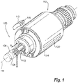
Fig. 1 is a perspective view of an exemplary embodiment of a generator arrangement constructed in accordance with the present disclosure, showing a generator rotor connected to a gas turbine engine by an input member; -
Fig. 2 is a cross-sectional side view of the generator arrangement ofFig. 1 , showing an actuator member engaging an input member ramp to disconnect the generator from the gas turbine engine; -
Fig. 3 is a schematic view of a controller of the generator arrangement ofFig. 1 , showing the controller synchronizing issue of a disconnect command to an actuator module based on rotational position of the input member; -
Fig. 4 is a flowchart of a method of disconnecting the generator and gas turbine engine in the generator arrangement ofFig. 1 , showing determinations made when a disconnect command is issued to a controller in the generator arrangement; and -
Figs. 5-7 are process flow diagram of an exemplary embodiment of a method of disconnecting a generator input member from a source of mechanical rotation, showing steps of the method. - Reference will now be made to the drawings wherein like reference numerals identify similar structural features or aspects of the subject disclosure. For purposes of explanation and illustration, and not limitation, a partial view of an exemplary embodiment of a disconnect coupling in accordance with the disclosure is shown in
Fig. 1 and is designated generally byreference character 100. Other embodiments of disconnect couplings, generator arrangements, and methods of disconnecting generators from sources of mechanical rotation in accordance with the disclosure, or aspects thereof, are provided inFigs. 2-7 , as will be described. The systems and methods described herein can be used for disconnecting generators from engines in aircraft electrical systems, though the present disclosure is not limited to aircraft electrical systems or to generators in general. - Referring to
Fig. 1 , agenerator arrangement 102 is shown.Generator arrangement 102 is operably connected to a prime mover, e.g., agas turbine engine 104, by a reduction gear arrangement anddisconnect coupling 100 including adrive member 108 and aninput member 110.Generator arrangement 102 includes astator portion 112 withstator windings 116 for providing electrical power to an aircraft electrical system (not shown for purposes of clarity) androtor portion 114.Rotor portion 114 is supported for rotation relative tostator portion 112 about arotation axis 118 and includes permanent magnets, bars, and/orwindings 120, which are electromagnetically coupled tostator windings 116 for inducing electrical current instator windings 116 asrotor portion 114 rotates relative tostator portion 112 aboutrotation axis 118. -
Input member 110 is slidingly received withinrotor portion 114 alongrotation axis 118 and is movable alongrotation axis 118 between a connected position A and a disconnected (i.e. separated) position B relative toprime mover 104, gear arrangement, anddrive member 108. In the connected position A,input member 110 is fixed in rotation relative to drivemember 108,input member 110 receiving mechanical rotation 122 (shown inFig. 2 ) fromdrive member 108 such thatrotor portion 114 andinput member 110 rotate in concert with one another aboutrotation axis 118. In the disconnected position B,input member 110 is rotationally free relative to drivemember 108,input member 110 being axially disconnected fromdrive member 108 such thatinput member 110 androtor portion 114 may be rotationally fixed relative tostator portion 112. - With reference to
Fig. 2 , abiasing element 124 is arranged to exert a biasing force 126 axially oninput member 110. Biasing force 126urges input member 110 axially alongrotation axis 118, towardsdrive member 108, such thatface teeth 128 disposed on aface 130 ofinput member 110 intermesh withcorresponding face teeth 132 disposed on anopposing face 134 ofdrive member 108. As will be appreciated by those of skill in the art in view of the present disclosure,mechanical rotation 122 is communicated between drive member 108 (shown inFig. 1 ) andinput member 110 when drivemember face teeth 132 intermesh with inputmember face teeth 128, biasing force 126 biasing operating to urgeinput member 110 towards connected position A (shown inFig 1 ) such that the teeth ofinput member 110 and drivemember 108 are intermeshed. -
Input member 110 includes a ramp 136 disposed on an end proximate to faceteeth 128. Ramp 136 extends aboutinput member 110 androtation axis 118, defining acam surface 138.Cam surface 138 has an actuator member-receiving surface extending about a portion of the circumference ofinput member 110 which, from the perspective of a rotationally fixedactuator member 140, has an axial position that varies according to the rotational position ofinput member 110.Cam surface 138 bounds arecess 142 for receiving anactuator member end 144 ofactuator member 140,recess 142 being interrupted by an axially extendingrib portion 146.Actuator member 140 is mechanically engagable withinput member 110 such rotation of theinput member 110 while the actuator member is mechanically engaged withinput member 110 causesinput member 110 to move axially away from and to thereby rotational ly disengage fromdrive member 108. - An
actuator module 147 is operably connected toactuator member 140.Actuator module 147 is arranged to moveactuator member 140 between a disengaged position C, whereinactuator member 140 is mechanically disconnected frominput member 110, and an engaged position D, whereinactuator member 140 is in mechanical contact withinput member 110. Upon receipt of adisconnect command signal 152,actuator module 147 movesactuator member 140 from the disengaged position C to the engaged position D, whereinactuator member end 144 will generally be received intorecess 142. - As will be appreciated by those of skill in the art in view of the present disclosure, within a relatively limited angular range of rotation, axially extending
rib portion 146 can be aligned withactuator member 140. When within this angular rangeactuator member end 144 can impact axially extendingrib portion 146, potentially sliding across the surface ofinput member 110 in frictional engagement with the surface ofinput member 110 prior to seating withinrecess 142. The impact as well as the frictional forces associated with the sliding can causeactuator member end 144 to generate debris, e.g., chips 148, frominput member 110. Chips 148 can reduce reliability or availability ofgenerator arrangement 102 if not managed, such as by removal, e.g., through lubricant fluid changes, and/or through impoundment, e.g., in a lubricant filter, etc. Accordingly, to reduce (or eliminate) chip generation,generator arrangement 100 includes acontroller 150 for synchronizing movement ofactuator member 140 from the disengaged position C according to rotational position ofinput member 110 such thatactuator member end 144 does not impactrib portion 146. - With reference to
Fig. 3 ,controller 150 is shown.Controller 150 is connected betweenactuator module 147 and adisconnect command lead 154, and is arranged to synchronize receipt ofdisconnect command signal 152 atactuator module 147 with rotational position ofinput member 110. Aposition sensor 156 coupled toinput member 110 is configured to report rotational position ofinput member 110 with arotational position signal 158.Position sensor 156 provides rotational position signal 158 tocontroller 150 through asensor lead 160. Rotational position signal 158 may be a 'pull', triggered by receipt ofdisconnect command signal 152 bycontroller 150. Alternatively, rotational position signal 158 may be a 'push', provided continuously byposition sensor 156 irrespective of presence ofdisconnect command signal 152 ondisconnect command lead 154. -
Controller 150 includes asynchronization block 162, adelay block 164, and anoperator block 166.Sensor lead 160 is connected to synchronization block 162 and is configured to provide rotational position signal 158 tosynchronization block 162. Disconnectcommand lead 154 is connected to bothsynchronization block 162 anddelay block 164, and is configured to providedisconnect command signal 152 to bothsynchronization block 162 and delay block 164 simultaneously.Delay block 164 is connected to operator block 166 by a delayblock output lead 168, and is arranged to toll adelay interval 170 of predetermined duration upon receipt ofdisconnect command signal 152, and thereafter providedisconnect command signal 152 tooperator block 166. -
Synchronization block 162 is connected to operator block 166 by a synchronization block output lead 172, and is arranged to providedisconnect command signal 152 to operator block 166 in synchronization with rotational position ofinput member 110. In thisrespect synchronization block 162 is arranged to compare rotational position ofinput member 110, as indicated byrotational position signal 158, with a predetermined target disconnect angle range (or window) 174. When rotational position signal 158 is outside target disconnect angle range (or window) 174,synchronization block 162 refrains from providingdisconnect command signal 152 tooperator block 166. When rotational position signal 158 is within target disconnect angle range (or window) 174,synchronization block 162 providesdisconnect command signal 152 tooperator block 166. As will be appreciated by those of skill in the art, the target disconnect angle range varies with rotor speed for a given actuator member movement speed and distance. Thus, as generator rotational speed increases, the likelihood of generating chips increases. -
Operator block 166 is connected toactuator module 147 via an actuatormodule input lead 168, and is arranged to provide adisconnect command signal 152 toactuator module 147 without discrimination. In thisrespect operator block 166 is arranged to providedisconnect command signal 152 toactuator module 147 via actuatorinput module lead 168 when provided by either delay block 164 orsynchronization block 162. Therefore, when a disconnect command is issued tocontroller 150, such as from a user input arranged on aircraft flight deck by way of non-limiting example, arrival of the command signal atactuator module 147 is delayed by a relatively short period of time (e.g., the amount of time required to forrecess 142 to become align with actuator member end 144),actuator module 147 thereafter receivingdisconnect command signal 152. It is contemplated thatdelay interval 170 be selected to correspond to a relatively short period of times, e.g., to one or two revolutions ofinput member 110 whenrotation 122 aboutrotation axis 118 is about 24000 rotations per minute. Thereafter, in the event thatsynchronization block 162 fails to providedisconnect command signal 152 within the relativelylonger delay interval 170, the delay interval tolls (i.e. the delay expires), and disconnectcommand signal 152 is provided throughoperator block 166 bydelay block 164 such thatactuator member 140 drives actuator member end 144 from disengaged position C to engaged position D. - With reference to
Fig. 4 , a flowchart of amethod 200 of disconnecting a generator, e.g., generator arrangement 102 (show inFig. 1 ), from a drive member, e.g., gas turbine engine 104 (shown inFig. 1 ), is shown.Method 200 includes receiving a disconnect command, e.g., disconnect command signal 152 (shown inFig. 2 ), to disconnect the generator from a source of mechanical rotation, as shown withbox 210. A rotational angle of an input member, e.g., input member 110 (shown inFig. 1 ) is received, as shown withblock 220, and compared with an input member target disconnect angle range , e.g., target disconnect angle range 174 (shown inFig. 3 ), as shown withbox 222. Determination is then made whether the input member rotational angle is within the target disconnect angle range, as shown withbox 224. - In the event that the input member rotational angle is not within the target disconnect angle range then the input member rotational position is monitored until it is within the target disconnect angle range, as shown with
arrow 226. In the event that the input member rotational position is within the target disconnect angle range, the input member is disconnected from the drive member by providing the disconnect command to an actuation module, e.g., actuator module 147 (shown inFig. 2 ), as shown withbox 228 and indicated witharrow 240. - Coincident with
operations 220 through 224/226, a delay interval is tolled. In this respect the intervening period of time between receipt of the disconnect command is calculated, as shown withbox 230. Duration of the intervening period is compared with a predetermined delay interval, e.g., delay interval 170 (shown inFig. 3 ), as shown withbox 232. In the event that the calculated intervening period is not within the delay interval, time since receipt of the disconnect command is successively re-calculated until the intervening period exceeds the delay interval the delay interval thereby being tolled, as shown witharrow 234. - Once the delay interval has tolled, determination is made as to whether the input member has been disconnected from the drive member, as shown with
box 236. In the event that the input member has been disconnected via issue of the disconnect command to the actuation module viastep 224, the process ends as, shown witharrow 238. In the event that no disconnect command has yet been issued to the actuation module, the disconnect command is issued to the actuation module, as shown witharrow 242. - With reference to
Figs. 5-7 , an exemplary embodiment of amethod 300 of disconnecting a generator, e.g., generator arrangement 102 (shown inFig. 1 ), from a source of mechanical rotation, e.g., gas turbine engine 104 (shown inFig. 1 ), is shown.Method 300 includes receiving a disconnect command, e.g., disconnect command signal 152 (shown inFig. 2 ), as shown withbox 310.Method 300 also includes receiving a rotational angle of an input member, e.g., input member 110 (shown inFig. 1 ), a shown withbox 320. - The rotational angle is compared to a target disconnect angle range, e.g., target disconnect angle range 174 (shown in
Fig. 3 ), as shown inbox 330. Based on the comparison, separation of the input member and drive member can be delayed, as shown withbox 340 and indicated byarrow 332. Separation of the input member from the drive member can be delayed until toll of a delay interval, e.g., delay interval 170 (shown inFig. 3 ), as shown withbox 342. Separation of the input member from the drive member can be delayed until the rotational angle of the input member is within the target disconnect angle range, as shown withbox 344. Alternatively, in the event that the rotational position is suitable for disconnect, e.g., bridge 146 (shown inFig. 2 ) is not within the stroke of actuator member end 144 (shown inFig. 2 ), the input member can be disconnected from the drive member, as show withbox 350 and indicated witharrow 334. - The input member is be disconnected from the drive member by frictionally engaging the input member with an actuator member, e.g., actuator member 140 (shown in
Fig. 2 ), as shown withbox 352. Separation can occur when the comparison indicates that the rotational angle of the input member is within the target disconnect angle range, as shown inbox 356. Separation can occur when the comparison indicates that the rotational angle of the input member is outside of the target disconnect angle range, as shown inbox 354, such as when the delay interval has tolled without the received rotational angle of the input member indicating that the input member is within the target disconnect angle range during the delay interval. As will be appreciated by those of skill in the art in view of the present disclosure, separation based upon toll of the delay interval prevents the input member from being inseparable from the drive member in the event that the rotational position sensor fails and/or provides erroneous information during input member rotation. - The methods and systems of the present disclosure, as described above and shown in the drawings, provide for disconnect couplings and generator arrangements with superior properties, including reduced wear from contact between moving and stationary components during disconnect events. While the apparatus and methods of the subject disclosure have been shown and described with reference to preferred embodiments, those skilled in the art will readily appreciate that changes and/or modifications may be made thereto without departing from the scope of the subject disclosure.
Claims (15)
- A method of disconnecting a generator from a drive member, comprising:receiving a disconnect command;receiving a rotational angle of an input member;comparing the input member rotational angle with a target disconnect angle range; anddetermining whether to disconnect the input member from the drive member based on the comparison of the input member rotational angle and the target disconnect angle range.
- The method as recited in claim 1, further comprising disconnecting the input member from the drive member by frictionally engaging the input member with an actuator member.
- The method as recited in claim 1, further comprising delaying disconnection when the rotational angle of the input member is outside the target disconnect angle range.
- The method as recited in claim 1, further comprising disconnecting the input member from the drive member when the rotational angle of the input member is in the target disconnect angle range; and/or disconnecting the input member from the drive member after tolling a delay interval irrespective of the rotational angle; and/or disconnecting the input member from the drive member when the rotational angle of the input member is outside of the target disconnect angle range.
- A disconnect coupling, comprising:a drive member for a generator;an input member being rotationally engaged with the drive member and having a ramp extending circumferentially about the input member;an actuator member mechanically engagable with the input member such that rotation of the input member while the actuator member is mechanically engaged with the input member causes the input member to move axially away from and to thereby rotationally disengage from the drive member; anda controller operably connected to the actuator member and configured to move the actuator member between the disengaged position and the engaged position based upon rotational position of the input member or upon toll of a delay interval.
- The disconnect coupling as recited in claim 5, wherein the controller is configured to receive a disconnect command, receive a rotational angle of the input member, compare the input member rotational angle with a target disconnect angle range, and determine whether the input member rotational angle is within the target disconnect angle range, and determine whether to disconnect the input member from the drive member based on the comparison of the input member rotational angle and the target disconnect angle range.
- The disconnect coupling as recited in claim 5, further comprising a rotational position sensor connected to the controller and configured to provide a signal with input member rotational position to the controller.
- The disconnect coupling as recited in claim 5, further comprising an actuation module connected between the controller and the actuator member to move the actuator member between the disengaged position and engaged positions upon receipt of a disconnect command.
- The disconnect coupling as recited in claim 5, wherein the controller includes:a disconnect command lead;a synchronization block connected to the disconnect command lead;a delay block connected to the disconnect command lead; andan operator block connected to the synchronization block and the delay block to provide a disconnect command received from the synchronization block or the delay block to an actuation module operably connected to the actuator module based on input member rotational angle or upon toll of a delay interval.
- The disconnect coupling as recited in claim 5, wherein the controller is configured to delay disconnection when the input member rotational angle is outside of the target disconnect angle range, and disconnect the input and drive members when the input member rotational angle is within the target disconnect angle range.
- The disconnect coupling as recited in claim 5, wherein the controller is configured to delay disconnection when the input member rotational angle is outside of the target disconnect angle range, and disconnect the input member from the drive member after toll of a delay interval.
- The disconnect coupling as recited in claim 5, wherein the actuator member is frictionally engaged to the input member in an engaged position; and/or wherein the actuator member is disconnected from the input member in a disengaged position.
- The disconnect coupling as recited in claim 5, further comprising a reduction gear arrangement mechanically coupled to the drive member for providing mechanical rotation to the input member.
- The disconnect coupling as recited in claim 5, further comprising a gas turbine engine mechanically coupled to the drive member to provide mechanical rotation to the input member.
- A generator arrangement, comprising:a stator having windings;a rotor having one or more permanent magnets, bars, and/or windings supported for rotation relative to the stator; anda disconnect coupling as recited in claim 5, wherein the rotor is seated about the input member and the input member is movable therein.
Applications Claiming Priority (1)
| Application Number | Priority Date | Filing Date | Title |
|---|---|---|---|
| US15/294,620 US10677292B2 (en) | 2016-10-14 | 2016-10-14 | Generator disconnect couplings |
Publications (2)
| Publication Number | Publication Date |
|---|---|
| EP3309421A1 true EP3309421A1 (en) | 2018-04-18 |
| EP3309421B1 EP3309421B1 (en) | 2020-11-25 |
Family
ID=60043117
Family Applications (1)
| Application Number | Title | Priority Date | Filing Date |
|---|---|---|---|
| EP17195545.3A Active EP3309421B1 (en) | 2016-10-14 | 2017-10-09 | Generator disconnect couplings |
Country Status (2)
| Country | Link |
|---|---|
| US (2) | US10677292B2 (en) |
| EP (1) | EP3309421B1 (en) |
Cited By (2)
| Publication number | Priority date | Publication date | Assignee | Title |
|---|---|---|---|---|
| GB2577744A (en) * | 2018-10-05 | 2020-04-08 | Safran Electrical & Power | Aircraft engine generator disconnect device with latch |
| EP4421342A3 (en) * | 2021-08-03 | 2024-09-11 | Hamilton Sundstrand Corporation | System and method to disconnect and brake a rotating device |
Families Citing this family (4)
| Publication number | Priority date | Publication date | Assignee | Title |
|---|---|---|---|---|
| EP3246538A1 (en) * | 2016-05-18 | 2017-11-22 | Siemens Aktiengesellschaft | Method for coupling a steam turbine and a gas turbine with a desired difference angle using target acceleration |
| US10641344B2 (en) * | 2017-11-22 | 2020-05-05 | Hamilton Sundstrand Corporation | Disconnect plunger for integrated drive generator |
| EP3852850B1 (en) * | 2018-09-17 | 2022-06-29 | Vectura Delivery Devices Limited | Dry powder inhaler |
| US11698111B1 (en) * | 2022-04-14 | 2023-07-11 | Hamilton Sundstrand Corporation | High ramp angle disconnect shaft |
Citations (4)
| Publication number | Priority date | Publication date | Assignee | Title |
|---|---|---|---|---|
| US4945780A (en) * | 1989-04-10 | 1990-08-07 | Bosma Machine And Tool Corporation | Drive unit for a monorail carrier |
| US20050236248A1 (en) * | 2004-04-21 | 2005-10-27 | Timken Us Corporation | Electrically actuated mechanical disconnect |
| US20100283341A1 (en) * | 2009-05-06 | 2010-11-11 | Grosskopf Andrew P | Decoupler shaft for high speed generator |
| US20120024652A1 (en) * | 2009-04-24 | 2012-02-02 | Toyota Jidosha Kabushiki Kaisha | Rotary meshing engagement apparatus |
Family Cites Families (13)
| Publication number | Priority date | Publication date | Assignee | Title |
|---|---|---|---|---|
| US2104265A (en) | 1934-12-24 | 1938-01-04 | Fmc Corp | Clutch mechanism |
| US2224192A (en) | 1937-09-24 | 1940-12-10 | Teletype Corp | Power transmitting mechanism |
| US3037598A (en) | 1957-07-05 | 1962-06-05 | Tickamatic Corp | One-revolution clutch |
| US4244455A (en) | 1978-10-17 | 1981-01-13 | The United States Of America As Represented By The Secretary Of The Navy | Rotary shaft decoupling mechanism |
| DE3935450C1 (en) * | 1989-10-25 | 1991-05-23 | Heidelberger Druckmaschinen Ag, 6900 Heidelberg, De | |
| GB0820232D0 (en) | 2008-11-05 | 2008-12-10 | Goodrich Control Sys Ltd | Releasable drive arrangement |
| US20120109569A1 (en) | 2010-10-27 | 2012-05-03 | General Electric Company | Diagnosis of bearing thermal anomalies in an electrical machine |
| DE102011085839A1 (en) * | 2011-11-07 | 2013-05-08 | Zf Friedrichshafen Ag | Coupling device with two couplable by means of a sliding sleeve coupling parts |
| US20130262025A1 (en) * | 2012-03-27 | 2013-10-03 | Hamilton Sundstrand Corporation | Extended range absolute position sensing |
| WO2014115248A1 (en) * | 2013-01-22 | 2014-07-31 | トヨタ自動車株式会社 | Engagement device |
| DE102014113937B3 (en) * | 2014-09-25 | 2016-03-03 | Gkn Driveline Bruneck Ag | Coupling arrangement and drive arrangement with a clutch arrangement |
| EP3002566A1 (en) | 2014-09-30 | 2016-04-06 | Alstom Technology Ltd | A system for compensating rotor vibrations |
| US9685841B2 (en) | 2014-11-12 | 2017-06-20 | Honeywell International Inc. | Resettable electro-mechanically actuated connection unit for generators |
-
2016
- 2016-10-14 US US15/294,620 patent/US10677292B2/en active Active
-
2017
- 2017-10-09 EP EP17195545.3A patent/EP3309421B1/en active Active
-
2020
- 2020-05-04 US US16/866,415 patent/US11226013B2/en active Active
Patent Citations (4)
| Publication number | Priority date | Publication date | Assignee | Title |
|---|---|---|---|---|
| US4945780A (en) * | 1989-04-10 | 1990-08-07 | Bosma Machine And Tool Corporation | Drive unit for a monorail carrier |
| US20050236248A1 (en) * | 2004-04-21 | 2005-10-27 | Timken Us Corporation | Electrically actuated mechanical disconnect |
| US20120024652A1 (en) * | 2009-04-24 | 2012-02-02 | Toyota Jidosha Kabushiki Kaisha | Rotary meshing engagement apparatus |
| US20100283341A1 (en) * | 2009-05-06 | 2010-11-11 | Grosskopf Andrew P | Decoupler shaft for high speed generator |
Cited By (4)
| Publication number | Priority date | Publication date | Assignee | Title |
|---|---|---|---|---|
| GB2577744A (en) * | 2018-10-05 | 2020-04-08 | Safran Electrical & Power | Aircraft engine generator disconnect device with latch |
| GB2577744B (en) * | 2018-10-05 | 2022-09-28 | Safran Electrical & Power | Aircraft engine generator disconnect device with latch |
| US11859557B2 (en) | 2018-10-05 | 2024-01-02 | Safran Electrical & Power | Aircraft engine generator disconnect device with latch |
| EP4421342A3 (en) * | 2021-08-03 | 2024-09-11 | Hamilton Sundstrand Corporation | System and method to disconnect and brake a rotating device |
Also Published As
| Publication number | Publication date |
|---|---|
| US20200263741A1 (en) | 2020-08-20 |
| EP3309421B1 (en) | 2020-11-25 |
| US10677292B2 (en) | 2020-06-09 |
| US11226013B2 (en) | 2022-01-18 |
| US20180106302A1 (en) | 2018-04-19 |
Similar Documents
| Publication | Publication Date | Title |
|---|---|---|
| US11226013B2 (en) | Generator disconnect couplings | |
| EP2243952B1 (en) | Engine starting apparatus | |
| US10873243B2 (en) | Electrical machine | |
| EP3776819B1 (en) | A generator having a disconnect mechanism | |
| US7728477B2 (en) | Dual purpose permanent magnet exciter | |
| EP2045907B1 (en) | Method to re-engage start of dynamoelectric machine | |
| EP3103969A1 (en) | Emergency shut-down detection system for a gas turbine | |
| US9188097B2 (en) | Starter with speed sensor assembly | |
| WO2007137398A1 (en) | Starting a gas turbine engine | |
| CN110291282B (en) | Air turbine starter with separator | |
| US10337944B2 (en) | Method and apparatus for turbine engine rotor automatic self balancing | |
| US10690196B2 (en) | Shaft decoupler for electric generator | |
| US10458341B2 (en) | Turboshaft engine for an aircraft equipped with an automatically-activated centraliser | |
| US20080069685A1 (en) | Device for Detecting a Fracture in the Shaft of a Gas Turbine, and Gas Turbine | |
| EP4421342A2 (en) | System and method to disconnect and brake a rotating device | |
| US20180216678A1 (en) | Automatically actuated disconnect couplings | |
| EP3790175A1 (en) | Generator arrangements and methods of generating electric power with generator arrangements | |
| CN113785144A (en) | Electromechanical actuator for generating an axial operating force | |
| US10393196B2 (en) | Engine accessory disconnect system | |
| EP3734807A1 (en) | Generator field amortisseur & spring locking mechanism | |
| US20220018401A1 (en) | Synchronized electromagnetic single plate clutch system | |
| EP4407205B1 (en) | Resetting an electromechanical disconnect | |
| CN115380455B (en) | Actuation system for aircraft engine lubrication pump and related aircraft | |
| CN109891545A (en) | For the engagement relay of electric machine and for driving the method for having the machine for the electricity for being preferably configured as starting device of engagement relay |
Legal Events
| Date | Code | Title | Description |
|---|---|---|---|
| PUAI | Public reference made under article 153(3) epc to a published international application that has entered the european phase |
Free format text: ORIGINAL CODE: 0009012 |
|
| STAA | Information on the status of an ep patent application or granted ep patent |
Free format text: STATUS: THE APPLICATION HAS BEEN PUBLISHED |
|
| AK | Designated contracting states |
Kind code of ref document: A1 Designated state(s): AL AT BE BG CH CY CZ DE DK EE ES FI FR GB GR HR HU IE IS IT LI LT LU LV MC MK MT NL NO PL PT RO RS SE SI SK SM TR |
|
| AX | Request for extension of the european patent |
Extension state: BA ME |
|
| STAA | Information on the status of an ep patent application or granted ep patent |
Free format text: STATUS: REQUEST FOR EXAMINATION WAS MADE |
|
| 17P | Request for examination filed |
Effective date: 20181012 |
|
| RBV | Designated contracting states (corrected) |
Designated state(s): AL AT BE BG CH CY CZ DE DK EE ES FI FR GB GR HR HU IE IS IT LI LT LU LV MC MK MT NL NO PL PT RO RS SE SI SK SM TR |
|
| REG | Reference to a national code |
Ref country code: DE Ref legal event code: R079 Ref document number: 602017028146 Country of ref document: DE Free format text: PREVIOUS MAIN CLASS: F16D0011140000 Ipc: F16D0011040000 |
|
| GRAP | Despatch of communication of intention to grant a patent |
Free format text: ORIGINAL CODE: EPIDOSNIGR1 |
|
| STAA | Information on the status of an ep patent application or granted ep patent |
Free format text: STATUS: GRANT OF PATENT IS INTENDED |
|
| RIC1 | Information provided on ipc code assigned before grant |
Ipc: F16D 23/12 20060101ALN20200408BHEP Ipc: F16D 48/06 20060101ALI20200408BHEP Ipc: F16D 11/04 20060101AFI20200408BHEP |
|
| INTG | Intention to grant announced |
Effective date: 20200424 |
|
| RIN1 | Information on inventor provided before grant (corrected) |
Inventor name: CAMPBELL, KRIS H. Inventor name: DELL, JONATHAN C. Inventor name: KATSUMATA, SHIN |
|
| GRAS | Grant fee paid |
Free format text: ORIGINAL CODE: EPIDOSNIGR3 |
|
| GRAA | (expected) grant |
Free format text: ORIGINAL CODE: 0009210 |
|
| STAA | Information on the status of an ep patent application or granted ep patent |
Free format text: STATUS: THE PATENT HAS BEEN GRANTED |
|
| AK | Designated contracting states |
Kind code of ref document: B1 Designated state(s): AL AT BE BG CH CY CZ DE DK EE ES FI FR GB GR HR HU IE IS IT LI LT LU LV MC MK MT NL NO PL PT RO RS SE SI SK SM TR |
|
| REG | Reference to a national code |
Ref country code: GB Ref legal event code: FG4D |
|
| REG | Reference to a national code |
Ref country code: CH Ref legal event code: EP |
|
| REG | Reference to a national code |
Ref country code: AT Ref legal event code: REF Ref document number: 1338675 Country of ref document: AT Kind code of ref document: T Effective date: 20201215 |
|
| REG | Reference to a national code |
Ref country code: DE Ref legal event code: R096 Ref document number: 602017028146 Country of ref document: DE |
|
| REG | Reference to a national code |
Ref country code: IE Ref legal event code: FG4D |
|
| REG | Reference to a national code |
Ref country code: AT Ref legal event code: MK05 Ref document number: 1338675 Country of ref document: AT Kind code of ref document: T Effective date: 20201125 |
|
| REG | Reference to a national code |
Ref country code: NL Ref legal event code: MP Effective date: 20201125 |
|
| PG25 | Lapsed in a contracting state [announced via postgrant information from national office to epo] |
Ref country code: RS Free format text: LAPSE BECAUSE OF FAILURE TO SUBMIT A TRANSLATION OF THE DESCRIPTION OR TO PAY THE FEE WITHIN THE PRESCRIBED TIME-LIMIT Effective date: 20201125 Ref country code: PT Free format text: LAPSE BECAUSE OF FAILURE TO SUBMIT A TRANSLATION OF THE DESCRIPTION OR TO PAY THE FEE WITHIN THE PRESCRIBED TIME-LIMIT Effective date: 20210325 Ref country code: NO Free format text: LAPSE BECAUSE OF FAILURE TO SUBMIT A TRANSLATION OF THE DESCRIPTION OR TO PAY THE FEE WITHIN THE PRESCRIBED TIME-LIMIT Effective date: 20210225 Ref country code: FI Free format text: LAPSE BECAUSE OF FAILURE TO SUBMIT A TRANSLATION OF THE DESCRIPTION OR TO PAY THE FEE WITHIN THE PRESCRIBED TIME-LIMIT Effective date: 20201125 Ref country code: GR Free format text: LAPSE BECAUSE OF FAILURE TO SUBMIT A TRANSLATION OF THE DESCRIPTION OR TO PAY THE FEE WITHIN THE PRESCRIBED TIME-LIMIT Effective date: 20210226 |
|
| PG25 | Lapsed in a contracting state [announced via postgrant information from national office to epo] |
Ref country code: AT Free format text: LAPSE BECAUSE OF FAILURE TO SUBMIT A TRANSLATION OF THE DESCRIPTION OR TO PAY THE FEE WITHIN THE PRESCRIBED TIME-LIMIT Effective date: 20201125 Ref country code: LV Free format text: LAPSE BECAUSE OF FAILURE TO SUBMIT A TRANSLATION OF THE DESCRIPTION OR TO PAY THE FEE WITHIN THE PRESCRIBED TIME-LIMIT Effective date: 20201125 Ref country code: IS Free format text: LAPSE BECAUSE OF FAILURE TO SUBMIT A TRANSLATION OF THE DESCRIPTION OR TO PAY THE FEE WITHIN THE PRESCRIBED TIME-LIMIT Effective date: 20210325 Ref country code: PL Free format text: LAPSE BECAUSE OF FAILURE TO SUBMIT A TRANSLATION OF THE DESCRIPTION OR TO PAY THE FEE WITHIN THE PRESCRIBED TIME-LIMIT Effective date: 20201125 Ref country code: BG Free format text: LAPSE BECAUSE OF FAILURE TO SUBMIT A TRANSLATION OF THE DESCRIPTION OR TO PAY THE FEE WITHIN THE PRESCRIBED TIME-LIMIT Effective date: 20210225 Ref country code: SE Free format text: LAPSE BECAUSE OF FAILURE TO SUBMIT A TRANSLATION OF THE DESCRIPTION OR TO PAY THE FEE WITHIN THE PRESCRIBED TIME-LIMIT Effective date: 20201125 |
|
| REG | Reference to a national code |
Ref country code: LT Ref legal event code: MG9D |
|
| PG25 | Lapsed in a contracting state [announced via postgrant information from national office to epo] |
Ref country code: HR Free format text: LAPSE BECAUSE OF FAILURE TO SUBMIT A TRANSLATION OF THE DESCRIPTION OR TO PAY THE FEE WITHIN THE PRESCRIBED TIME-LIMIT Effective date: 20201125 |
|
| PG25 | Lapsed in a contracting state [announced via postgrant information from national office to epo] |
Ref country code: SK Free format text: LAPSE BECAUSE OF FAILURE TO SUBMIT A TRANSLATION OF THE DESCRIPTION OR TO PAY THE FEE WITHIN THE PRESCRIBED TIME-LIMIT Effective date: 20201125 Ref country code: RO Free format text: LAPSE BECAUSE OF FAILURE TO SUBMIT A TRANSLATION OF THE DESCRIPTION OR TO PAY THE FEE WITHIN THE PRESCRIBED TIME-LIMIT Effective date: 20201125 Ref country code: LT Free format text: LAPSE BECAUSE OF FAILURE TO SUBMIT A TRANSLATION OF THE DESCRIPTION OR TO PAY THE FEE WITHIN THE PRESCRIBED TIME-LIMIT Effective date: 20201125 Ref country code: EE Free format text: LAPSE BECAUSE OF FAILURE TO SUBMIT A TRANSLATION OF THE DESCRIPTION OR TO PAY THE FEE WITHIN THE PRESCRIBED TIME-LIMIT Effective date: 20201125 Ref country code: CZ Free format text: LAPSE BECAUSE OF FAILURE TO SUBMIT A TRANSLATION OF THE DESCRIPTION OR TO PAY THE FEE WITHIN THE PRESCRIBED TIME-LIMIT Effective date: 20201125 Ref country code: SM Free format text: LAPSE BECAUSE OF FAILURE TO SUBMIT A TRANSLATION OF THE DESCRIPTION OR TO PAY THE FEE WITHIN THE PRESCRIBED TIME-LIMIT Effective date: 20201125 |
|
| REG | Reference to a national code |
Ref country code: DE Ref legal event code: R097 Ref document number: 602017028146 Country of ref document: DE |
|
| PG25 | Lapsed in a contracting state [announced via postgrant information from national office to epo] |
Ref country code: DK Free format text: LAPSE BECAUSE OF FAILURE TO SUBMIT A TRANSLATION OF THE DESCRIPTION OR TO PAY THE FEE WITHIN THE PRESCRIBED TIME-LIMIT Effective date: 20201125 |
|
| PLBE | No opposition filed within time limit |
Free format text: ORIGINAL CODE: 0009261 |
|
| STAA | Information on the status of an ep patent application or granted ep patent |
Free format text: STATUS: NO OPPOSITION FILED WITHIN TIME LIMIT |
|
| PG25 | Lapsed in a contracting state [announced via postgrant information from national office to epo] |
Ref country code: IT Free format text: LAPSE BECAUSE OF FAILURE TO SUBMIT A TRANSLATION OF THE DESCRIPTION OR TO PAY THE FEE WITHIN THE PRESCRIBED TIME-LIMIT Effective date: 20201125 Ref country code: NL Free format text: LAPSE BECAUSE OF FAILURE TO SUBMIT A TRANSLATION OF THE DESCRIPTION OR TO PAY THE FEE WITHIN THE PRESCRIBED TIME-LIMIT Effective date: 20201125 Ref country code: AL Free format text: LAPSE BECAUSE OF FAILURE TO SUBMIT A TRANSLATION OF THE DESCRIPTION OR TO PAY THE FEE WITHIN THE PRESCRIBED TIME-LIMIT Effective date: 20201125 |
|
| 26N | No opposition filed |
Effective date: 20210826 |
|
| PG25 | Lapsed in a contracting state [announced via postgrant information from national office to epo] |
Ref country code: SI Free format text: LAPSE BECAUSE OF FAILURE TO SUBMIT A TRANSLATION OF THE DESCRIPTION OR TO PAY THE FEE WITHIN THE PRESCRIBED TIME-LIMIT Effective date: 20201125 |
|
| PG25 | Lapsed in a contracting state [announced via postgrant information from national office to epo] |
Ref country code: ES Free format text: LAPSE BECAUSE OF FAILURE TO SUBMIT A TRANSLATION OF THE DESCRIPTION OR TO PAY THE FEE WITHIN THE PRESCRIBED TIME-LIMIT Effective date: 20201125 |
|
| REG | Reference to a national code |
Ref country code: CH Ref legal event code: PL |
|
| PG25 | Lapsed in a contracting state [announced via postgrant information from national office to epo] |
Ref country code: IS Free format text: LAPSE BECAUSE OF FAILURE TO SUBMIT A TRANSLATION OF THE DESCRIPTION OR TO PAY THE FEE WITHIN THE PRESCRIBED TIME-LIMIT Effective date: 20210325 |
|
| REG | Reference to a national code |
Ref country code: BE Ref legal event code: MM Effective date: 20211031 |
|
| PG25 | Lapsed in a contracting state [announced via postgrant information from national office to epo] |
Ref country code: MC Free format text: LAPSE BECAUSE OF FAILURE TO SUBMIT A TRANSLATION OF THE DESCRIPTION OR TO PAY THE FEE WITHIN THE PRESCRIBED TIME-LIMIT Effective date: 20201125 |
|
| PG25 | Lapsed in a contracting state [announced via postgrant information from national office to epo] |
Ref country code: LU Free format text: LAPSE BECAUSE OF NON-PAYMENT OF DUE FEES Effective date: 20211009 Ref country code: BE Free format text: LAPSE BECAUSE OF NON-PAYMENT OF DUE FEES Effective date: 20211031 |
|
| PG25 | Lapsed in a contracting state [announced via postgrant information from national office to epo] |
Ref country code: LI Free format text: LAPSE BECAUSE OF NON-PAYMENT OF DUE FEES Effective date: 20211031 Ref country code: CH Free format text: LAPSE BECAUSE OF NON-PAYMENT OF DUE FEES Effective date: 20211031 |
|
| PG25 | Lapsed in a contracting state [announced via postgrant information from national office to epo] |
Ref country code: IE Free format text: LAPSE BECAUSE OF NON-PAYMENT OF DUE FEES Effective date: 20211009 |
|
| PG25 | Lapsed in a contracting state [announced via postgrant information from national office to epo] |
Ref country code: HU Free format text: LAPSE BECAUSE OF FAILURE TO SUBMIT A TRANSLATION OF THE DESCRIPTION OR TO PAY THE FEE WITHIN THE PRESCRIBED TIME-LIMIT; INVALID AB INITIO Effective date: 20171009 |
|
| P01 | Opt-out of the competence of the unified patent court (upc) registered |
Effective date: 20230522 |
|
| PG25 | Lapsed in a contracting state [announced via postgrant information from national office to epo] |
Ref country code: CY Free format text: LAPSE BECAUSE OF FAILURE TO SUBMIT A TRANSLATION OF THE DESCRIPTION OR TO PAY THE FEE WITHIN THE PRESCRIBED TIME-LIMIT Effective date: 20201125 |
|
| PG25 | Lapsed in a contracting state [announced via postgrant information from national office to epo] |
Ref country code: MK Free format text: LAPSE BECAUSE OF FAILURE TO SUBMIT A TRANSLATION OF THE DESCRIPTION OR TO PAY THE FEE WITHIN THE PRESCRIBED TIME-LIMIT Effective date: 20201125 |
|
| PG25 | Lapsed in a contracting state [announced via postgrant information from national office to epo] |
Ref country code: MT Free format text: LAPSE BECAUSE OF FAILURE TO SUBMIT A TRANSLATION OF THE DESCRIPTION OR TO PAY THE FEE WITHIN THE PRESCRIBED TIME-LIMIT Effective date: 20201125 |
|
| PGFP | Annual fee paid to national office [announced via postgrant information from national office to epo] |
Ref country code: GB Payment date: 20250923 Year of fee payment: 9 |
|
| PGFP | Annual fee paid to national office [announced via postgrant information from national office to epo] |
Ref country code: FR Payment date: 20250924 Year of fee payment: 9 |
|
| PG25 | Lapsed in a contracting state [announced via postgrant information from national office to epo] |
Ref country code: TR Free format text: LAPSE BECAUSE OF FAILURE TO SUBMIT A TRANSLATION OF THE DESCRIPTION OR TO PAY THE FEE WITHIN THE PRESCRIBED TIME-LIMIT Effective date: 20201125 |
|
| PGFP | Annual fee paid to national office [announced via postgrant information from national office to epo] |
Ref country code: DE Payment date: 20250923 Year of fee payment: 9 |