EP3309375A1 - Engine system and saddle ride-type vehicle - Google Patents
Engine system and saddle ride-type vehicle Download PDFInfo
- Publication number
- EP3309375A1 EP3309375A1 EP16811167.2A EP16811167A EP3309375A1 EP 3309375 A1 EP3309375 A1 EP 3309375A1 EP 16811167 A EP16811167 A EP 16811167A EP 3309375 A1 EP3309375 A1 EP 3309375A1
- Authority
- EP
- European Patent Office
- Prior art keywords
- intake
- range
- angle
- normal
- engine
- Prior art date
- Legal status (The legal status is an assumption and is not a legal conclusion. Google has not performed a legal analysis and makes no representation as to the accuracy of the status listed.)
- Withdrawn
Links
Images



Classifications
-
- F—MECHANICAL ENGINEERING; LIGHTING; HEATING; WEAPONS; BLASTING
- F02—COMBUSTION ENGINES; HOT-GAS OR COMBUSTION-PRODUCT ENGINE PLANTS
- F02N—STARTING OF COMBUSTION ENGINES; STARTING AIDS FOR SUCH ENGINES, NOT OTHERWISE PROVIDED FOR
- F02N11/00—Starting of engines by means of electric motors
- F02N11/08—Circuits specially adapted for starting of engines
-
- B—PERFORMING OPERATIONS; TRANSPORTING
- B62—LAND VEHICLES FOR TRAVELLING OTHERWISE THAN ON RAILS
- B62M—RIDER PROPULSION OF WHEELED VEHICLES OR SLEDGES; POWERED PROPULSION OF SLEDGES OR SINGLE-TRACK CYCLES; TRANSMISSIONS SPECIALLY ADAPTED FOR SUCH VEHICLES
- B62M7/00—Motorcycles characterised by position of motor or engine
- B62M7/02—Motorcycles characterised by position of motor or engine with engine between front and rear wheels
-
- F—MECHANICAL ENGINEERING; LIGHTING; HEATING; WEAPONS; BLASTING
- F01—MACHINES OR ENGINES IN GENERAL; ENGINE PLANTS IN GENERAL; STEAM ENGINES
- F01L—CYCLICALLY OPERATING VALVES FOR MACHINES OR ENGINES
- F01L13/00—Modifications of valve-gear to facilitate reversing, braking, starting, changing compression ratio, or other specific operations
-
- F—MECHANICAL ENGINEERING; LIGHTING; HEATING; WEAPONS; BLASTING
- F02—COMBUSTION ENGINES; HOT-GAS OR COMBUSTION-PRODUCT ENGINE PLANTS
- F02D—CONTROLLING COMBUSTION ENGINES
- F02D13/00—Controlling the engine output power by varying inlet or exhaust valve operating characteristics, e.g. timing
- F02D13/02—Controlling the engine output power by varying inlet or exhaust valve operating characteristics, e.g. timing during engine operation
-
- F—MECHANICAL ENGINEERING; LIGHTING; HEATING; WEAPONS; BLASTING
- F02—COMBUSTION ENGINES; HOT-GAS OR COMBUSTION-PRODUCT ENGINE PLANTS
- F02D—CONTROLLING COMBUSTION ENGINES
- F02D13/00—Controlling the engine output power by varying inlet or exhaust valve operating characteristics, e.g. timing
- F02D13/02—Controlling the engine output power by varying inlet or exhaust valve operating characteristics, e.g. timing during engine operation
- F02D13/0203—Variable control of intake and exhaust valves
- F02D13/0207—Variable control of intake and exhaust valves changing valve lift or valve lift and timing
- F02D13/0211—Variable control of intake and exhaust valves changing valve lift or valve lift and timing the change of valve timing is caused by the change in valve lift, i.e. both valve lift and timing are functionally related
-
- F—MECHANICAL ENGINEERING; LIGHTING; HEATING; WEAPONS; BLASTING
- F02—COMBUSTION ENGINES; HOT-GAS OR COMBUSTION-PRODUCT ENGINE PLANTS
- F02D—CONTROLLING COMBUSTION ENGINES
- F02D17/00—Controlling engines by cutting out individual cylinders; Rendering engines inoperative or idling
-
- F—MECHANICAL ENGINEERING; LIGHTING; HEATING; WEAPONS; BLASTING
- F02—COMBUSTION ENGINES; HOT-GAS OR COMBUSTION-PRODUCT ENGINE PLANTS
- F02D—CONTROLLING COMBUSTION ENGINES
- F02D29/00—Controlling engines, such controlling being peculiar to the devices driven thereby, the devices being other than parts or accessories essential to engine operation, e.g. controlling of engines by signals external thereto
- F02D29/02—Controlling engines, such controlling being peculiar to the devices driven thereby, the devices being other than parts or accessories essential to engine operation, e.g. controlling of engines by signals external thereto peculiar to engines driving vehicles; peculiar to engines driving variable pitch propellers
-
- F—MECHANICAL ENGINEERING; LIGHTING; HEATING; WEAPONS; BLASTING
- F02—COMBUSTION ENGINES; HOT-GAS OR COMBUSTION-PRODUCT ENGINE PLANTS
- F02N—STARTING OF COMBUSTION ENGINES; STARTING AIDS FOR SUCH ENGINES, NOT OTHERWISE PROVIDED FOR
- F02N19/00—Starting aids for combustion engines, not otherwise provided for
- F02N19/004—Aiding engine start by using decompression means or variable valve actuation
-
- F—MECHANICAL ENGINEERING; LIGHTING; HEATING; WEAPONS; BLASTING
- F02—COMBUSTION ENGINES; HOT-GAS OR COMBUSTION-PRODUCT ENGINE PLANTS
- F02N—STARTING OF COMBUSTION ENGINES; STARTING AIDS FOR SUCH ENGINES, NOT OTHERWISE PROVIDED FOR
- F02N19/00—Starting aids for combustion engines, not otherwise provided for
- F02N19/005—Aiding engine start by starting from a predetermined position, e.g. pre-positioning or reverse rotation
-
- F—MECHANICAL ENGINEERING; LIGHTING; HEATING; WEAPONS; BLASTING
- F02—COMBUSTION ENGINES; HOT-GAS OR COMBUSTION-PRODUCT ENGINE PLANTS
- F02N—STARTING OF COMBUSTION ENGINES; STARTING AIDS FOR SUCH ENGINES, NOT OTHERWISE PROVIDED FOR
- F02N99/00—Subject matter not provided for in the other groups of this subclass
- F02N99/002—Starting combustion engines by ignition means
- F02N99/006—Providing a combustible mixture inside the cylinder
-
- F—MECHANICAL ENGINEERING; LIGHTING; HEATING; WEAPONS; BLASTING
- F02—COMBUSTION ENGINES; HOT-GAS OR COMBUSTION-PRODUCT ENGINE PLANTS
- F02N—STARTING OF COMBUSTION ENGINES; STARTING AIDS FOR SUCH ENGINES, NOT OTHERWISE PROVIDED FOR
- F02N19/00—Starting aids for combustion engines, not otherwise provided for
- F02N19/005—Aiding engine start by starting from a predetermined position, e.g. pre-positioning or reverse rotation
- F02N2019/007—Aiding engine start by starting from a predetermined position, e.g. pre-positioning or reverse rotation using inertial reverse rotation
Definitions
- the present invention relates to an engine system and a straddled vehicle.
- Patent Document 1 JP 2014-77405 A
- crank angle is required to exceed an angle corresponding to an exhaust top dead center (overlap top dead center) during the reverse rotation of the crankshaft, an engine start time and an engine starting energy are increased.
- An object of the present invention is to provide an engine system and a straddled vehicle in which an engine can be started in a shorter time at lower energy.
- the engine can be started in a shorter time at lower energy.
- the motorcycle is an example of a straddled vehicle.
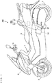
- Fig. 1 is a schematic side view showing a general configuration of a motorcycle according to a first embodiment of the present invention.
- a front fork 2 is provided at a front portion of a vehicle body 1 to be swingable to the right and the left.
- a handle 4 is attached to an upper end of the front fork 2, and a front wheel 3 is rotatably attached to a lower end of the front fork 2.
- a seat 5 is provided at a substantially central upper portion of the vehicle body 1.
- An ECU (Engine Control Unit) 6 and an engine unit EU are provided below the seat 5.
- the ECU 6 and the engine unit EU constitute an engine system 200.
- a rear wheel 7 is rotatably attached to a lower portion of a rear end of the vehicle body 1.
- the rear wheel 7 is driven by motive power generated by the engine unit EU so as to rotate the rear wheel 7.
- Fig. 2 is a schematic diagram for explaining the configuration of the engine system 200.
- the engine unit EU includes an engine 10 and a rotary electrical machine 14.
- the engine 10 is a single-cylinder four-cycle engine in this embodiment.
- the engine 10 includes a cylinder CY, a piston 11, a connecting rod 12, a crankshaft 13, an intake valve 15, an exhaust valve 16, a valve driver 17, an injector 18, and an ignition device 19.
- the piston 11 is provided to be reciprocatable in the cylinder CY and connected to the crankshaft 13 via the connecting rod 12.
- the crankshaft 13 is provided with the rotary electrical machine 14.
- the rotary electrical machine 14 can drive the crankshaft 13 in a forward direction or a reverse direction by electrical power supplied from a battery, not shown, and can also charge the battery by electrical power generated by the rotation of the crankshaft 13.
- the forward direction is a direction in which the crankshaft 13 is rotated during a normal operation of the engine 10, whereas the reverse direction is a direction opposite to the forward direction.
- the rotary electrical machine 14 transmits a torque directly to the crankshaft 13 without a reduction gear interposed therebetween. As such, the crankshaft 13 can be driven without any machine sounds generated by the reduction gear.
- Rotation of the crankshaft 13 in the forward direction is transmitted to the rear wheel 7, so that the rear wheel 7 is driven to rotate.
- a starter motor and a generator may be provided separately in place of the rotary electrical machine 14.
- a combustion chamber 31a is divided into sections by the cylinder CY and the piston 11.
- the combustion chamber 31a communicates with an intake passage 22 through an intake port 21 and communicates with an exhaust passage 24 through an exhaust port 23.
- An intake valve 15 is provided to open and close the intake port 21, and an exhaust valve 16 is provided to open and close the exhaust port 23.
- the intake valve 15 and the exhaust valve 16 are driven by the valve driver 17.
- a throttle valve TV for adjusting a flow rate of air flowing in from the outside is provided at the intake passage 22.
- the injector 18 is configured to inject fuel into the intake passage 22.
- the ignition device 19 includes an ignition coil and an ignition plug and is configured to ignite a fuel-air mixture in the combustion chamber 31a.
- the fuel injected by the injector 18 is mixed with air and then guided to the combustion chamber 31a, and the fuel-air mixture in the combustion chamber 31a is ignited by the ignition device 19.
- the reciprocating motion of the piston 11 due to the combustion of the fuel-air mixture is converted into the rotational motion of the crankshaft 13.
- the torque of the crankshaft 13 is transmitted to the rear wheel 7 of Fig. 1 , so that the rear wheel 7 is driven.
- the ECU 6 includes a CPU (Central Processing Unit) and a memory, for example. A microcomputer may be used in place of the CPU and the memory.
- the ECU 6 is electrically connected with a main switch 40, a starter switch 41, an intake pressure sensor 42, a crank angle sensor 43, and a current sensor 44.
- the main switch 40 is provided below the handle 4 of Fig. 1 , for example, and the starter switch 41 is provided on the handle 4 of Fig. 1 , for example.
- the main switch 40 and the starter switch 41 are operated by a rider.
- the intake pressure sensor 42 detects pressure in the intake passage 22.
- the crank angle sensor 43 detects an angle representing a rotational position of the crankshaft 13 (hereinafter referred to as crank angle).
- the current sensor 44 detects a current flowing through the rotary electrical machine 14 (hereinafter referred to as motor current).
- the operations of the main switch 40 and the starter switch 41 are applied as operation signals to the ECU 6, and the results of a detection by the intake pressure sensor 42, the crank angle sensor 43, and the current sensor 44 are applied as detection signals to the ECU 6.
- the ECU 6 controls the rotary electrical machine 14, the injector 18, and the ignition device 19 on the basis of the applied operation and detection signals.
- the engine 10 is started when the main switch 40 of Fig. 2 is turned on and the starter switch 41 is turned on, whereas the engine 10 is stopped when the main switch 40 of Fig. 2 is turned off.
- Start-up of the engine 10 refers to the combustion in the combustion chamber 31a being started by the start of the fuel injection by the injector 18 and the ignition by the ignition device 19.
- Stopping of the engine 10 refers to the combustion in the combustion chamber 31a being stopped by stopping at least one of the fuel injection by the injector 18 and the ignition by the ignition device 19.
- the idle stop condition may include a condition that relates to at least one of, for example, throttle opening (the degree of opening of a throttle valve TV), vehicle speed, and rotation speed of the engine 10, and may further include another condition such as a condition that a brake lever is operated.
- the re-start condition refers to, for example, the throttle opening being larger than 0 when an accelerator grip is operated, and may include another condition such as a condition that the operation of the brake lever is released.
- Fig. 3 is a diagram for explaining an operation during the normal operation of the engine unit EU (hereinafter also referred to as normal operation).
- Fig. 4 is a diagram for explaining a reverse rotation start-up operation of the engine unit EU.
- a top dead center through which the piston 11 passes at the time of shifting from the compression stroke to the expansion stroke is referred to as a compression top dead center
- a top dead center through which the piston 11 passes at the time of shifting from the exhaust stroke to the intake stroke is referred to as an exhaust top dead center, during the normal operation of the engine 10.
- a bottom dead center through which the piston 11 passes at the time of shifting from the intake stroke to the compression stroke is referred to as an intake bottom dead center
- a bottom dead center through which the piston 11 passes at the time of shifting from the expansion stroke to the exhaust stroke is referred to as an expansion bottom dead center.
- Ranges of the crank angle that correspond to the intake stroke, the compression stroke, the expansion stroke, and the exhaust stroke during the normal operation of the engine 10 are referred to as a normal intake range, a normal compression range, a normal expansion range, and a normal exhaust range, respectively.
- the range of the crank angle which is equivalent to two rotations (720 degrees) of the crankshaft 13 is represented by one circle.
- the two rotations of the crankshaft 13 are equivalent to one cycle of the engine 10.
- the crank angle sensor 43 of Fig. 2 detects a rotational position in a range in which the crankshaft 13 makes one rotation (360 degrees).
- the ECU 6 determines to which one of the two rotations of the crankshaft 13 equivalent to one cycle of the engine 10 the angle detected by the crank angle sensor 43 corresponds.
- the ECU 6 can acquire the rotational position in the range of two rotations (720 degrees) of the crankshaft 13 as the crank angle.
- an angle A0 is a crank angle when the piston 11 ( Fig. 2 ) is positioned at the exhaust top dead center
- an angle A2 is a crank angle when the piston 11 is positioned at the compression top dead center
- an angle A1 is a crank angle when the piston 11 is positioned at the intake bottom dead center
- an angle A3 is a crank angle when the piston 11 is positioned at the expansion bottom dead center.
- An arrow R1 represents a direction in which the crank angle changes during the forward rotation of the crankshaft 13
- an arrow R2 represents a direction in which the crank angle changes during the reverse rotation of the crankshaft 13.
- Arrows P1 to P4 represent directions in which the piston 11 moves during the forward rotation of the crankshaft 13.
- Arrows P5 to P8 represent directions in which the piston 11 moves during the reverse rotation of the crankshaft 13.
- the crankshaft 13 ( Fig. 2 ) is rotated forward, so that the crank angle changes in the direction of the arrow R1.
- the piston 11 ( Fig. 2 ) is lowered in the range from the angle A0 to the angle A1, raised in the range from the angle A1 to the angle A2, lowered in the range from the angle A2 to the angle A3, and raised in the range from the angle A3 to the angle A0.
- the range from the angle A0 to the angle A1 is equivalent to the normal intake range and corresponds to the intake stroke during the normal operation.
- the range from the angle A1 to the angle A2 is equivalent to the normal compression range and corresponds to the compression stroke during the normal operation.
- the range from the angle A2 to the angle A3 is equivalent to the normal expansion range and corresponds to the expansion stroke during the normal operation.
- the range from the angle A3 to the angle A0 is equivalent to the normal exhaust range and corresponds to the exhaust stroke during the normal operation.
- the fuel is injected into the intake passage 22 ( Fig. 2 ) by the injector 18 ( Fig. 2 ).
- the angle A11 is positioned at a further advanced angle than the angle A0.
- the intake port 21 ( Fig. 2 ) is subsequently opened by the intake valve 15 ( Fig. 2 ) in a range from an angle A12 to an angle A13.
- the angle A12 is positioned at a further retarded angle than the angle A11 and at a further advanced angle than the angle A0
- the angle A13 is positioned at a further retarded angle than the angle A1.
- a fuel-air mixture containing air and fuel is introduced into the combustion chamber 31a ( Fig. 2 ) through the intake port 21.
- the fuel-air mixture in the combustion chamber 31a ( Fig. 2 ) is ignited by the ignition device 19 ( Fig. 2 ).
- the angle A14 is positioned at a further advanced angle than the angle A2.
- the ignition of the fuel-air mixture causes explosion in the combustion chamber 31a (combustion of the fuel-air mixture).
- Energy generated by the combustion of the fuel-air mixture turns to a driving force of the piston 11.
- the exhaust port 23 ( Fig. 2 ) is opened by the exhaust valve 16 ( Fig. 2 ) in the range from an angle A15 to an angle A16.
- the angle A15 is positioned at a further advanced angle than the angle A3, and the angle A16 is positioned at a further retarded angle than the angle A0 in the forward direction. This allows the combusted gas to be discharged from the combustion chamber 31a through the exhaust port 23.
- crank angle is adjusted to an angle A20 in the normal compression range before the reverse rotation start-up operation.
- the angle A20 is an example of a reverse rotation starting range.
- the reverse rotation start-up operation includes a reverse rotation operation in which the rotary electrical machine 14 rotates the crankshaft 13 in the reverse direction.
- the reverse rotation operation causes the crank angle to change in the direction of the arrow R2.
- the piston 11 is lowered in the range from the angle A2 to the angle A1, raised in the range from the angle A1 to the angle A0, lowered in the range from the angle A0 to the angle A3, and raised in the range from the angle A3 to the angle A2.
- the direction in which the piston 11 moves during the reverse rotation of the crankshaft 13 is opposite to the direction in which the piston 11 moves during the forward rotation of the crankshaft 13.
- the angle A21 is an example of a start-up fuel injection range within the normal compression range. In the reverse direction, the angle A21 is positioned at a further retarded angle than the angle A20.
- the intake port 21 ( Fig. 2 ) is opened by the intake valve 15 ( Fig. 2 ) in a range from an angle A22 to an angle A23.
- the range from the angle A22 to the angle A23 is an example of a start-up intake range.
- the angle A22 is positioned at a further retarded angle than the angle A21 and at a further advanced angle than the angle A1, and the angle A23 is positioned at a slightly further retarded angle than the angle A1.
- the piston 11 is lowered, and therefore, when the intake port 21 is opened in the range from the angle A22 to the angle A23, a fuel-air mixture including air and fuel is introduced into the combustion chamber 31a through the intake port 21 from the intake passage 22.
- the intake valve 15 is not lifted, and the intake port 21 is not opened.
- the fuel-air mixture introduced into the combustion chamber 31a is compressed.
- the fuel-air mixture in the combustion chamber 31a is ignited by the ignition device 19 ( Fig. 2 ), and also the direction in which the crankshaft 13 is driven by the rotary electrical machine 14 is switched from the reverse direction to the forward direction.
- the angle A24 is positioned at a further retarded angle than the angle A23 and at a further advanced angle than the angle A0.
- the angle A24 is an example of a start-up ignition range.
- the fuel-air mixture is ignited by the ignition device 19.
- the crankshaft 13 is driven in the forward direction by combustion of the fuel-air mixture, so that the forward torque of the crankshaft 13 is increased.
- the crank angle can exceed the angle A2 corresponding to the first compression top dead center. After that, the engine unit EU is shifted to the aforementioned normal operation.
- the combusted gas may be discharged from the combustion chamber 31a through the exhaust port 23 after the reverse rotation operation of the rotary electrical machine 14 and before the crank angle reaches the angle A2 corresponding to the first compression top dead center.
- the intake port 21 is not opened in the range from the angle A23 to the angle A22, but the exhaust port 23 may be opened in part of the normal compression range.
- the combusted gas which is generated by the ignition at the angle A24, is discharged through the exhaust port 23 without flowing out to the intake passage 22.
- the fuel-air mixture can appropriately be introduced into the combustion chamber 31a in the subsequent intake stroke, and combustion can appropriately be generated in the ignition operation at the angle A14 ( Fig. 3 ).
- the intake port 21 may be opened in the range from the angle A23 to the angle A22, and the exhaust port 23 may be opened in part of the normal compression range both during and immediately after the reverse rotation operation of the rotary electrical machine 14.
- the combusted gas is further prevented from flowing out to the intake passage 22 as compared to a case where only the intake port 21 is opened immediately after the reverse rotation operation.
- the fuel-air mixture can appropriately be introduced into the combustion chamber 31a in the subsequent intake stroke, and the combustion can appropriately be generated.
- the range of the crank angle in which the intake port 21 and the exhaust port 23 are opened is constant during and immediately after the reverse rotation operation, the configuration and the operation of the valve driver 17 can be simplified.
- a configuration in which an exhaust cam acting on the exhaust valve 16 is switched can be utilized, similarly to the example of Fig. 8 described below.
- start-up intake range includes part of the normal compression range and part of the normal intake range in this example, the start-up intake range may include only part of the normal compression range.
- Figs. 5 to 7 are flowcharts showing the engine start-up process.
- the engine start-up process is performed when the main switch 40 and the starter switch 41 of Fig. 2 are turned on, or when the idle stop condition as described above is satisfied, for example.
- the ECU 6 determines whether the current crank angle is stored in the memory (step S1). For example, the current crank angle is not stored immediately after the main switch 40 is turned on, whereas the current crank angle is stored with the engine 10 stopped when the idle stop condition is satisfied.
- the ECU 6 controls the rotary electrical machine 14 such that the crankshaft 13 is rotated forward (step S2).
- the torque of the crankshaft 13 by the rotary electrical machine 14 is adjusted based on a detection signal from the current sensor 44 ( Fig. 2 ) such that the crank angle does not exceed the angle A2 corresponding to the compression top dead center ( Figs. 3 and 4 ).
- step S3 determines whether a specified time period has elapsed after the rotation of the crankshaft 13 is started in step S2 (step S3). If the specified time period has not elapsed, the ECU 6 controls the rotary electrical machine 14 such that the forward rotation of the crankshaft 13 is continued. After the specified time period has elapsed, the ECU 6 controls the rotary electrical machine 14 such that the forward rotation of the crankshaft 13 is stopped (step S4). Thus, the crank angle is adjusted to around the angle A20 of Fig. 4 .
- step S2 when the crankshaft 13 is rotated in the forward direction, the crank angle may be detected, and then the crank angle may be adjusted to the angle A20 of Fig. 4 based on a detected value of the crank angle.
- step S5 when the current crank angle is stored, the ECU 6 determines whether the current angle is around the angle A20 ( Fig. 4 ) (step S5). For example, if the difference between the current crank angle and the angle A20 is within a predetermined acceptable range, it is determined that the current crank angle is around the angle A20. In contrast, if the difference between the current crank angle and the angle A20 is out of the acceptable range, it is determined that the current angle is not around the angle A20.
- step S6 If the current crank angle is not around the angle A20, the ECU 6 controls the rotary electrical machine 14 such that the crankshaft 13 is rotated forward (step S6). Then, the ECU 6 determines whether the current crank angle has reached the angle A20 based on detection results of the intake pressure sensor 42 and the crank angle sensor 43 (step S7). When the current crank angle has not reached the angle A20, the ECU 6 controls the rotary electrical machine 14 such that the forward rotation of the crankshaft 13 is continued. When the current crank angle has reached the angle A20, the ECU 6 controls the rotary electrical machine 14 such that the forward rotation of the crankshaft 13 is stopped (step S4). Thus, the crank angle is adjusted to the angle A20 of Fig. 4 .
- step S11 of Fig. 6 After the crank angle is adjusted to around the angle A20 due to the forward rotation of the crankshaft 13, a process of step S11 of Fig. 6 is carried out. If the current crank angle is around the angle A20 in step S5, the process of step S11 of Fig. 6 is directly carried out.
- the ECU 6 determines whether the engine 10 is in an idle stop state at the current time (step S11). If the engine 10 is not in the idle stop state, the ECU 6 proceeds to step S13. If the engine 10 is in the idle stop state, the ECU 6 determines whether the re-start condition is satisfied (step S12). The ECU 6 repeats the process of step S12 until the re-start condition is satisfied. If the re-start condition is satisfied, the ECU 6 proceeds to step S13.
- step S13 the ECU 6 performs a timeout setting for the engine start-up process. Specifically, an elapsed time is measured from that point of time. When the elapsed time has reached a predetermined termination time, the engine start-up process is forcibly terminated (steps S25 to S27 described below).
- the ECU 6 controls the rotary electrical machine 14 such that the crankshaft 13 is rotated in reverse (step S14).
- the ECU 6 determines whether the current crank angle has reached the angle A21 of Fig. 4 based on detection signals from the intake pressure sensor 42 ( Fig. 2 ) and the crank angle sensor 43 ( Fig. 2 ) (step S15).
- the ECU 6 repeats the process of step S15 until the current crank reaches the angle A21.
- the ECU 6 controls the injector 18 such that the fuel is injected to the intake passage 22 ( Fig. 2 ) (step S16).
- the ECU 6 may control the injector 18 such that when the crank angle has reached the angle A21, a pulse signal is applied from the crank angle sensor 43 to the ECU 6, and the fuel is injected in response to the pulse signal.
- the ECU 6 determines whether the motor current has reached a predetermined threshold value based on the detection signal from the current sensor 44 (step S21). In this case, the motor current becomes larger as the crank angle comes closer to the angle A0 of Fig. 4 . In this example, when the crank angle has reached the angle A24 of Fig. 4 , the motor current has reached the threshold value. It may be determined whether the crank angle has reached the angle A24 based on the crank angle detected by the crank angle sensor 43 in place of the motor current detected by the current sensor 44.
- the ECU 6 controls the rotary electrical machine 14 such that the reverse rotation of the crankshaft 13 is stopped (step S22), and controls the ignition device 19 such that the fuel-air mixture in the combustion chamber 31a is ignited (step S23). Also, the ECU 6 controls the rotary electrical machine 14 such that the crankshaft 13 is rotated in the forward direction (step S24). Thus, the ECU 6 terminates the engine start-up process. After that, the ECU 6 performs a control operation corresponding to the normal operation of Fig. 3 .
- the ECU 6 determines whether the predetermined termination time has elapsed after the timeout setting of step S13 of Fig. 6 (step S25).
- a problem or some trouble may be experienced with the engine unit EU, e.g., the trouble may include an operational failure of the rotary electrical machine 14, an operational failure of the valve driver 17 or the like. Because of such trouble with the engine unit EU, the predetermined termination time may sometimes have elapsed after the timeout setting while the current flowing through the rotary electrical machine 14 does not reach the threshold value. If the termination time has not elapsed, the ECU 6 returns to the process of step S21.
- the ECU 6 controls the rotary electrical machine 14 such that the reverse rotation of the crankshaft 13 is stopped (step S26), and also warns the rider that the trouble has occurred in the engine unit EU (step S27). Specifically, an alarm lamp, not shown, for example, is lit. Thus, the ECU 6 terminates the engine start-up process.
- the reverse rotation start-up operation of Fig. 4 is implemented by such an engine start-up process.
- Fig. 8 is a diagram showing an example of a specific configuration of the valve driver 17.
- the valve driver 17 of Figs. 8(a) and 8(b) includes a camshaft 170, an intake rocker arm RA1, and an exhaust rocker arm RA2.
- the camshaft 170 includes a shaft member 171, an intake cam structure 172, and an exhaust cam 173.
- the shaft member 171 is rotated in conjunction with the rotation of the crankshaft 13.
- the intake cam structure 172 and the exhaust cam 173 are provided at the shaft member 171 such that the intake cam structure 172 and the exhaust cam 173 are rotated integrally with the shaft member 171.
- the intake cam structure 172 includes a main intake cam 172a and a sub intake cam 172b.
- the main intake cam 172a and the sub intake cam 172b are configured to be integrally movable in an axial direction with respect to the shaft member 171.
- the engine 10 includes an intake cam driver 175 that drives the intake cam structure 172.
- the intake cam driver 175 moves the intake cam structure 172 between a normal position at which the main intake cam 172a abuts against the intake rocker arm RA1 (the position shown in Fig. 8(a) ) and a start-up position in which the sub intake cam 172b abuts against the intake rocker arm RA1 (the position shown in Fig. 8(b) ).
- the exhaust cam 173 abuts against the exhaust rocker arm RA2.
- the intake cam structure 172 is held in the normal position of Fig. 8(a) during the forward rotation of the crankshaft 13.
- the main intake cam 172a drives the intake valve 15 of Fig. 2 via the intake rocker arm RA1
- the exhaust cam 173 drives the exhaust valve 16 of Fig. 2 via the exhaust rocker arm RA2.
- the main intake cam 172a is configured to lift the intake valve 15 in the range from the angle A12 to the angle A13 of Fig. 3 and to lift the exhaust valve 16 in the range from the angle A15 to the angle A16 in the forward direction.
- the intake cam structure 172 is held in the start-up position of Fig. 8(b) during the reverse rotation of the crankshaft 13.
- the sub intake cam 173b drives the intake valve 15 of Fig. 2 via the intake rocker arm RA1.
- the sub intake cam 173b is configured to lift the intake valve 15 in the range from the angle A22 to the angle A23 of Fig. 4 and not to lift the intake valve 15 in the range from the angle A23 to the angle A0 in the reverse direction.
- the main intake cam 172a and the sub intake cam 173b are selectively used during the forward rotation and during the reverse rotation of the crankshaft 13.
- the intake valve 15 can be lifted at a time suitable for each of the normal operation and the reverse rotation start-up operation without complication of the configuration of the valve driver 17.
- the intake port 21 is opened, and the fuel-air mixture is introduced into the combustion chamber 31a. Also, when the crank angle is in the normal intake range, the fuel-air mixture in the combustion chamber 31a is compressed. After that, when the crank angle is at the angle A24 before reaching the angle A0 corresponding to the exhaust top dead center, the fuel-air mixture in the combustion chamber 31a is ignited, and its combustion energy drives the crankshaft 13 in the forward direction.
- the angle range of the reverse rotation of the crankshaft 13 is small (specifically not more than 360 degrees)
- the time period for which the crankshaft 13 is rotated in reverse is shortened.
- the engine 10 can be started in a shorter time at lower energy.
- the crank angle is adjusted to the reverse rotation starting range (angle A20) before the reverse rotation start-up operation of the crankshaft 13.
- the fuel-air mixture can appropriately be introduced into the combustion chamber 31a, and the introduced fuel-air mixture can appropriately be compressed in the reverse rotation start-up operation.
- the fuel-air mixture can appropriately be combusted.
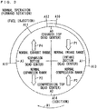
- FIG. 9 is a diagram for explaining the reverse rotation start-up operation of the engine unit EU in the second embodiment.
- the difference of the example of Fig. 9 from the example of Fig. 4 is that the intake port 21 ( Fig. 2 ) is opened in a range from an angle A26 to an angle A27, not in the range from the angle A22 ( Fig. 4 ) to the angle A23 ( Fig. 4 ).
- the angle A26 is positioned at a further advanced angle than the angle A1, and positioned at a further retarded angle than the angle A13 of Fig. 3 or at a position equal to the angle A13.
- the angle A27 is positioned at a further retarded angle than the angle A1.
- the range from the angle A26 to the angle A27 is an example of the start-up intake range.
- the range from the angle A26 to the angle A27 is included in a range of the crank angle in which the intake port 21 is opened in the normal operation (the range from the angle A12 to the angle A13 of Fig. 3 ).
- the piston 11 is lowered in the range from the angle A26 to the angle A1. Therefore, when the intake port 21 is opened in the range from A26 to the angle A1, the fuel-air mixture in the intake passage 22 is introduced into the combustion chamber 31a through the intake port 21.
- the fuel-air mixture introduced into the combustion chamber 31a is compressed, and the fuel-air mixture in the combustion chamber 31a is ignited by the ignition device 19 ( Fig. 2 ) at the angle A24.
- the crankshaft 13 is driven in the forward direction by the combustion of the fuel-air mixture, so that the crank angle exceeds the angle A2 corresponding to the first compression top dead center. Then, the engine unit EU is shifted to the normal operation.
- start-up intake range includes part of the normal compression range and part of the normal intake range in this example, the start-up intake range may include only part of the normal compression range. Also, while the fuel injection by the injector 18 is carried out in the same crank angle range as the example of Fig. 4 , and the ignition by the ignition device 19 is carried out in the same crank angle range as the example of Fig. 4 , the fuel injection by the injector 18 and the ignition by the ignition device 19 may be carried out in another crank angle range.
- the fuel injection by the injector 18 may be carried out in a range from a further retarded angle than the angle A21 to a further advanced angle than the angle A26 in the reverse direction
- the ignition by the ignition device 19 may be carried out in a range from a further retarded angle than the angle A27 to a further advanced angle than the angle A24 in the reverse direction.
- Fig. 10 is a diagram showing an example of a specific configuration of the valve driver 17 in the second embodiment.
- the example of Fig. 10 differs from the example of Fig. 8 in the following point.
- the camshaft 170 includes a main intake cam 172c and a sub intake cam 172d in place of the intake cam structure 172 of Fig. 8 .
- the main intake cam 172c and the sub intake cam 172d are fixed to the shaft member 171.
- Fig. 11 is a diagram for explaining cam profiles of the main intake cam 172c and the sub intake cam 172d.
- the main intake cam 172c has a cam nose CN1
- the sub intake cam 172d has a cam nose CN2.
- the entire cam nose CN2 is provided to overlap part of the cam nose CN1.
- a working angle ⁇ 1 of the main intake cam 172c is larger than a working angle ⁇ 2 of the sub intake cam 172d
- a lift amount LA1 of the main intake cam 172c is larger than a lift amount LA2 of the sub intake cam 172d.
- the cam nose CN1 corresponds to the range from the angle A12 to the angle A13 of Fig. 3
- the cam nose CN2 corresponds to the range from the angle A26 to the angle A27 of Fig. 9 .
- the valve driver 17 includes intake rocker arms RA1a, RA1b in place of the intake rocker arm RA1 of Fig. 8 .
- the intake rocker arm RA1a is provided to be swingable and abuttable against the main intake cam 172c
- the intake rocker arm RA1b is provided to be swingable and abuttable against the sub intake cam 172d.
- the intake rocker arm RA1b abuts against an upper end of the intake valve 15.
- the intake valve 15 is lifted by the swinging of the intake rocker arm RA1b.
- the intake rocker arm RA1a is provided with a hole H1
- the intake rocker arm RA1b is provided with a hole H2.
- the holes H1, H2 extend in a common direction.
- a connecting pin 181 and a biasing member 182 are disposed in the hole H2.
- the engine 10 includes a pin driver 180 that drives the connecting pin 181.
- the pin driver 180 moves the connecting pin 181 between a storage position in which a tip of the connecting pin 181 is stored in the hole H2 (the position of Fig. 10(a) ) and an insertion position in which the tip of the connecting pin 181 is inserted in the hole H1 (the position of Fig. 10(b) ).
- the connecting pin 181 is in the storage position of Fig. 10(a)
- the intake rocker arms RA1a, RA1b are swung independently of each other.
- the connecting pin 181 is in the insertion position of Fig. 10(b)
- the intake rocker arms RA1a, RA1b are integrally swung.
- the connecting pin 181 is held in the storage position of Fig. 10(a) .
- the intake rocker arm RA1a is swung depending on the cam profile of the main intake cam 172c
- the intake rocker arm RA1b is swung depending on the cam profile of the sub intake cam 172d.
- the crank angle range in which the intake valve 15 is lifted depends on the cam profile of the sub intake cam 172d and does not depend on the cam profile of the main intake cam 172c.
- the intake valve 15 is lifted in the range from the angle A26 to the angle A27 of Fig. 9 .
- the connecting pin 181 is held in the insertion position of Fig. 10(b) .
- the working angle and the lift amount of the main intake cam 172c are larger than those of the sub intake cam 172d.
- the intake rocker arms RA1a, RA1b are integrally swung depending on the cam profile of the main intake cam 172c.
- the crank angle range in which the intake valve 15 is lifted depends on the cam profile of the main intake cam 172c and does not depend on the cam profile of the sub intake cam 172d.
- the intake valve 15 is lifted in the range from the angle A12 to the angle A13 of Fig. 3 .
- the intake valve 15 can be lifted at a time suitable for each of the normal operation and the reverse rotation start-up operation.
- the crank angle range, in which the intake valve 15 is lifted can be switched only by the movement of the connecting pin 181.
- the operation of the valve driver 17 can be switched with the simple configuration.
- Fig. 12 is a schematic side view for explaining the configuration of an engine unit EU according to the third embodiment.
- the engine unit EU of Fig. 12 includes an engine 10A in place of the engine 10 of Fig. 2 .
- the engine 10A is a two-cylinder four-cycle engine and includes a first cylinder CY1 and a second cylinder CY2.
- Each of the first and second cylinders CY1, CY2 is provided with a piston 11 and has a combustion chamber 31a formed therein.
- Each piston 11 is connected to a crankshaft 13 via a connecting rod 12.
- the piston 11 in the second cylinder CY2 is positioned at the exhaust top dead center when the piston 11 in the first cylinder CY1 is positioned at the compression top dead center, and the piston 11 in the second cylinder CY2 is positioned at the compression top dead center when the piston 11 in the first cylinder CY1 is positioned at the exhaust top dead center. Accordingly, combustion in the first cylinder CY1 and combustion in the second cylinder CY2 are carried out alternately at substantially the same time interval.
- the intake valve 15, the exhaust valve 16, the injector 18, and the ignition device 19 of Fig. 2 are provided for each of the first and second cylinders CY1, CY2.
- the configuration of a peripheral portion of each of the first and second cylinders CY1, CY2 is similar to that of the peripheral portion of the cylinder CY of Fig. 2 .
- Fig. 13 is a diagram for explaining a normal operation of the engine unit EU of Fig. 12 .
- an operation in the first cylinder CY1 is the same as the operation in the cylinder CY of the above-described first embodiment.
- the piston 11 ( Fig. 12 ) is positioned at the exhaust top dead center when the crank angle is the angle A0, the piston 11 is positioned at the intake bottom dead center when the crank angle is the angle A1, the piston 11 is positioned at the compression top dead center when the crank angle is the angle A2, and the piston 11 is positioned at the expansion bottom dead center when the crank angle is the angle A3.
- the piston 11 ( Fig. 2 ) is lowered in the range from the angle A0 to the angle A1, raised in the range from the angle A1 to the angle A2, lowered in the range from the angle A2 to the angle A3, and raised in the range from the angle A3 to the angle A0.
- the range from the angle A0 to the angle A1 is equivalent to the normal intake range
- the range from the angle A1 to the angle A2 is equivalent to the normal compression range
- the range from the angle A2 to the angle A3 is equivalent to the normal expansion range
- the range from the angle A3 to the angle A0 is equivalent to the normal exhaust range.
- Fuel is injected by the injector 18 ( Fig. 2 ) at the angle A11, and the intake port 21 ( Fig. 2 ) is opened by the intake valve 15 ( Fig. 2 ) in the range from the angle A12 to the angle A13, so that a fuel-air mixture is introduced into the combustion chamber 31a ( Fig. 12 ).
- the fuel-air mixture in the combustion chamber 31a is ignited by the ignition device 19 ( Fig. 2 ).
- the exhaust port 23 is opened by the exhaust valve 16 ( Fig. 2 ), so that combusted gas is discharged from the combustion chamber 31a.
- a direction in which the piston 11 moves in the second cylinder CY2 is the same as a direction in which the piston 11 moves in the first cylinder CY1.
- the piston 11 ( Fig. 12 ) is positioned at the compression top dead center when the crank angle is the angle A0, the piston 11 is positioned at the expansion bottom dead center when the crank angle is the angle A1, the piston 11 is positioned at the exhaust top dead center when the crank angle is the angle A2, and the piston 11 is positioned at the intake bottom dead center when the crank angle is the angle A3.
- the range from the angle A2 to the angle A3 is equivalent to the normal intake range
- the range from the angle A3 to the angle A0 is equivalent to the normal compression range
- the range from the angle A0 to the angle A1 is equivalent to the normal expansion range
- the range from the angle A1 to the angle A2 is equivalent to the normal exhaust range.
- the fuel is injected into the intake passage 22 ( Fig. 2 ) by the injector 18 ( Fig. 2 ) at an angle A41, and the intake port 21 ( Fig. 2 ) is opened by the intake valve 15 ( Fig. 2 ) in the range from an angle A42 to an angle A43, so that the fuel-air mixture is introduced into the combustion chamber 31a ( Fig. 12 ).
- the fuel-air mixture in the combustion chamber 31a ( Fig. 12 ) is ignited by the ignition device 19 ( Fig. 2 ) at an angle A44.
- the exhaust port 23 ( Fig. 2 ) is opened by the exhaust valve 16 ( Fig.
- the angles A41 to A46 of Fig. 13(b) differ by 360 degrees from the angles A11 to A16 of Fig. 13(a) , respectively.
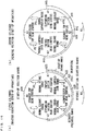
- Figs. 14 and 15 are diagrams for explaining a reverse rotation start-up operation of the engine unit EU of Fig. 12 .
- the fuel-air mixture is selectively combusted in one of the first and second cylinders CY1, CY2 during the reverse rotation start-up operation based on the crank angle of the stopped engine 10A.
- the angle A0 corresponds to the compression top dead center of the second cylinder CY2
- the angle A2 corresponds to the compression top dead center of the first cylinder CY1.
- a large torque is required for the crank angle to pass through the angle A0 or to pass through the angle A2.
- the fuel-air mixture is combusted in the first cylinder CY1 during the reverse rotation start-up operation.
- the fuel is injected at the angle A21 while the crankshaft 13 is rotated in reverse, and the fuel-air mixture is introduced into the combustion chamber 31a in the range from the angle A22 to the angle A23, so that the fuel-air mixture in the combustion chamber 31a is ignited at the angle A24.
- combustion can be generated in the first cylinder CY1 while the crank angle does not pass through the angles A2, A0, which correspond respectively to the compression top dead centers of the first cylinder and the second cylinder CY2.
- the crankshaft 13 is driven in the forward direction by energy of the combustion, whereby the crank angle can exceed the angles A0, A2.
- the fuel-air mixture is combusted in the second cylinder CY2 in the reverse rotation start-up operation.
- the fuel is injected at an angle A51 while the crankshaft 13 is rotated in reverse, and the fuel-air mixture is introduced into the combustion chamber 31a in a range from an angle A52 to an angle A53, so that the fuel-air mixture in the combustion chamber 31a is ignited at an angle A54.
- the angle A50 is an example of the reverse rotation starting range and is within the normal compression range.
- the angle A51 is an example of the start-up fuel injection range and is within the normal compression range.
- the range from the angle A52 to the angle A53 is an example of the start-up intake range, and the angle A54 is an example of the start-up ignition range.
- the angles A50 to A54 of Fig. 15(b) differ by 360 degrees from the angles A20 to A24 of Fig. 15(a) , respectively.
- combustion can be generated in the second cylinder CY2 while the crank angle does not pass through the angles A2, A0, which correspond respectively to the compression top dead centers of the first cylinder CY1 and the second cylinder CY2.
- the crankshaft 13 is driven in the forward direction by energy of the combustion, whereby the crank angle can exceed the angles A0, A2.
- the introduction, the compression and the combustion of the fuel-air mixture are carried out in one of the first and second cylinders CY1, CY2, whereby the start-up of the engine 10A can be carried out in a shorter time at lower energy.
- Fig. 16 is a diagram for explaining another example of the reverse rotation start-up operation of the engine unit EU of Fig. 12 . A difference of the example of Fig. 16 from the example of Fig. 15 will now be described.
- the reverse rotation start-up operation is performed such that the fuel-air mixture is combusted in the first cylinder CY1 after the crank angle is adjusted to the angle A20, similarly to the example of Fig. 15(a) .
- crank angle of the stopped engine 10A is within the range AR2 of Fig. 14
- pressure in the first cylinder CY1 is lowered while the crankshaft 13 is rotated in reverse.
- Fig. 16(a) the range from the angle A3 to the angle A1 in the reverse direction is set as a reduced pressure range.
- the exhaust port 23 ( Fig. 2 ) of the first cylinder CY1 is opened by a pressure reducing mechanism, not shown.
- the crank angle can be adjusted to the angle A20.
- the reverse rotation start-up operation is performed such that the fuel-air mixture is combusted in the first cylinder CY1, similarly to the example of Fig. 15(a) .
- the fuel-air mixture is not combusted in the second cylinder CY2 in the reverse rotation start-up operation.
- the intake port 21 and the exhaust port 23 in the second cylinder CY2 are opened also during the reverse rotation start-up operation in the same crank angle range as that during the normal operation.
- the reduced pressure range is not limited to the example of Fig. 16(a) .
- the range from the angle A3 to the angle A2 may be set as the reduced pressure range, or alternatively, part of the range from the angle A3 to the angle A2 may be set as the reduced pressure range.
- an increase in rotational resistance of the crankshaft 13 due to an increase in pressure in the first cylinder CY1 is reduced.
- crank angle may be adjusted to the angle A20 by reducing the pressure in the second cylinder CY2 while the crankshaft 13 is rotated in the forward direction, instead of reducing the pressure in the first cylinder CY1 while the crankshaft 13 is rotated in reverse.
- the range from the angle A3 to the angle A0 in the forward direction is set as the reduced pressure range.
- the pressure in the second cylinder CY2 is reduced in the reduced pressure range while the crankshaft 13 is rotated forward, so that the crank angle can exceed the angle A0 corresponding to the compression top dead center of the second cylinder CY2.
- the crank angle can be adjusted to the angle A20. Accordingly, the reverse rotation start-up operation can be performed similarly to the example of Fig. 15(a) .
- the present invention is not limited to this.
- the present invention may be applied to an engine system and a motorcycle including a multi-cylinder engine with three or more cylinders.
- the present invention is not limited to this.
- the present invention may be applied to another straddled vehicle such as a motor tricycle, an ATV (All-Terrain Vehicle) or the like.
- the engine system 200 is an example of an engine system
- the engines 10, 10A are examples of an engine
- the rotary electrical machine 14 is an example of a rotation driver
- the crankshaft 13 is an example of a crankshaft
- the ECU 6 is an example of a controller
- the valve driver 17 is an example of a valve driver
- the intake cam driver 175 or the pin driver 180 is an example of a switch
- the main intake cams 172a, 172c are examples of a normal intake cam
- the sub intake cams 172b, 172d are examples of a start-up intake cam
- the intake rocker arm RA1a is an example of a first intake rocker arm
- the intake rocker arm RA1b is an example of a second intake rocker arm.
- the motorcycle 100 is an example of a straddled vehicle
- the rear wheel 7 is an example of a drive wheel
- the vehicle body 1 is an example of a main body.
- the present invention is applicable to various types of engine systems and straddled vehicles.
Landscapes
- Engineering & Computer Science (AREA)
- Mechanical Engineering (AREA)
- Chemical & Material Sciences (AREA)
- Combustion & Propulsion (AREA)
- General Engineering & Computer Science (AREA)
- Transportation (AREA)
- Output Control And Ontrol Of Special Type Engine (AREA)
- Electrical Control Of Air Or Fuel Supplied To Internal-Combustion Engine (AREA)
- Combined Controls Of Internal Combustion Engines (AREA)
Abstract
Description
- The present invention relates to an engine system and a straddled vehicle.
- In a straddled vehicle such as a motorcycle, at the time of a start-up operation of an engine, a larger torque is required for a crank angle to exceed an angle corresponding to a first compression top dead center. Therefore, there is a technique for rotating a crankshaft in a reverse direction in order to enhance startability of the engine.
- In an engine system described in
Patent Document 1, during start-up of an engine, a fuel-air mixture is introduced into a combustion chamber while a crankshaft is rotated in a reverse direction. With the fuel-air mixture in the combustion chamber being compressed by the rotation of the crankshaft in the reverse direction, the fuel-air mixture in the combustion chamber is ignited. The crankshaft is driven to rotate in a forward direction by the combustion energy of the fuel-air mixture, so that a forward torque of the crankshaft is increased. - Patent Document 1:
JP 2014-77405 A - In the above-described method, however, since the crank angle is required to exceed an angle corresponding to an exhaust top dead center (overlap top dead center) during the reverse rotation of the crankshaft, an engine start time and an engine starting energy are increased.
- An object of the present invention is to provide an engine system and a straddled vehicle in which an engine can be started in a shorter time at lower energy.
-
- (1) According to one aspect of the present invention, an engine system includes an engine, a rotation driver that rotates a crankshaft of the engine in a forward direction and in a reverse direction, and a controller that controls the engine and the rotation driver, a range of a crank angle corresponding to an intake stroke during normal operation or a normal running is defined as a normal intake range, and the range of the crank angle corresponding to a compression stroke during the normal operation is defined as a normal compression range, the normal compression range includes at least part of a start-up intake range, and the normal intake range includes a start-up ignition range, the controller controls the rotation driver during start-up of the engine to perform a reverse rotation operation for rotating the crankshaft in the reverse direction such that the crank angle passes through the start-up intake range and reaches the start-up ignition range, and the controller controls the engine during the reverse rotation operation of the rotation driver such that a fuel-air mixture is introduced into a combustion chamber through an intake port when the crank angle is in the start-up intake range, the fuel-air mixture in the combustion chamber is compressed when the crank angle is in the normal intake range, and the fuel-air mixture in the combustion chamber is ignited when the crank angle is in the start-up ignition range.
In this engine system, during the start-up of the engine, the crankshaft is rotated in reverse such that the crank angle reaches the start-up ignition range across the start-up intake range. At least part of the start-up intake range is in the normal compression range, and the start-up ignition range is in the normal intake range. The fuel-air mixture is introduced into the combustion chamber when the crank angle is in the start-up intake range, and the fuel-air mixture in the combustion chamber is compressed when the crank angle is in the normal intake range. After that, when the crank angle is in the start-up ignition range, the fuel-air mixture in the combustion chamber is ignited and then combusted. Thus, the crankshaft is driven in the forward direction, and a forward torque of the crankshaft is increased. In this case, since an angle range of the reverse rotation of the crankshaft is small, a time period for which the crankshaft is rotated in reverse is shortened. Thus, the engine can be started in a shorter time at lower energy. - (2) The normal compression range may include a reverse rotation starting range that is positioned at a further advanced angle than the start-up intake range in the reverse direction, and the controller may control the rotation driver such that the crank angle is adjusted to be in the reverse rotation starting range before the reverse rotation operation.
In this case, even if there is a variation in crank angle of the stopped engine, the crank angle is adjusted to be in the reverse rotation starting range before the start-up of the engine. As such, during the reverse rotation of the crankshaft, the fuel-air mixture can appropriately be introduced into the combustion chamber, and the introduced fuel-air mixture can appropriately be compressed. Thus, the fuel-air mixture can appropriately be combusted. - (3) The normal compression range may include a start-up fuel injection range that is positioned at a further advanced angle than the start-up intake range in the reverse direction, and the controller may control the engine during the reverse rotation operation of the rotation driver such that fuel is injected into an intake passage when the crank angle is in the start-up fuel injection range. In this case, the fuel-air mixture can appropriately be introduced into the combustion chamber.
- (4) The engine may include a valve driver that drives an intake valve and an exhaust valve, and a switch that switches an operation of the valve driver, the valve driver may include a normal intake cam that lifts the intake valve at least in the normal intake range, and a start-up intake cam that lifts the intake valve in the start-up intake range and does not lift the intake valve in a portion of the normal intake range excluding the start-up intake range, and the switch may switch the operation of the valve driver such that the normal intake cam drives the intake valve during the normal operation, and the start-up intake cam drives the intake valve during the reverse rotation operation of the rotation driver. In this case, the intake port can be opened at a time suitable for each of the normal operation and the reverse rotation operation without complication of the configuration.
- (5) The switch may switch the operation of the valve driver between a state where the normal intake cam drives the intake valve and a state where the start-up intake cam drives the intake valve by moving the normal intake cam and the start-up intake cam. In this case, the operation of the valve driver can appropriately be switched in any relationship between a working angle of the normal intake cam and a working angle of the start-up intake cam.
- (6) The normal intake cam may be provided to lift the intake valve in a normal lift range that includes the normal intake range and the start-up intake range, the valve driver may further include a first intake rocker arm that abuts against the normal intake cam, and a second intake rocker arm that is abuttable against the start-up intake cam and drives the intake valve, and the switch may switch the operation of the valve driver between a state where the first and second intake rocker arms swing independently of each other and a state where the first and second intake rocker arms swing integrally.
In this case, with the first and second intake rocker arms swinging integrally, the normal intake cam causes the first and second intake rocker arms to swing integrally, whereby the intake valve can be lifted in the normal lift range. On the other hand, with the first and second intake rocker arms swinging independently of each other, the start-up intake cam causes the second intake rocker arm to swing separately from the first intake rocker arm, whereby the intake valve can be lifted in the start-up intake range. Thus, the operation of the valve driver can be switched with a simple configuration. - (7) The engine may discharge combusted gas from the combustion chamber through an exhaust port after the reverse rotation operation of the rotation driver and before the crank angle reaches an angle corresponding to a first compression top dead center. In this case, the combusted gas is inhibited from flowing out to the intake passage after the reverse rotation operation. Thus, the combusted gas remaining in the intake passage is prevented from interrupting a subsequent intake stroke.
- (8) The engine does not have to open the intake port after the reverse rotation operation of the rotation driver and before the crank angle reaches the angle corresponding to the first compression top dead center. In this case, the combusted gas is discharged through the exhaust port without flowing out to the intake passage after the reverse rotation operation. Thus, the fuel-air mixture can appropriately be introduced into the combustion chamber in the subsequent intake stroke.
- (9) The engine may open the intake port in the start-up intake range and open the exhaust port in part of the normal compression range during the reverse rotation operation of the rotation driver, and also after the reverse rotation operation of the rotation driver and before the crank angle reaches the angle corresponding to the first compression top dead center. In this case, the intake port and the exhaust port are each opened in a certain respective crank angle range both during and after the reverse rotation operation. Thus, it is possible to inhibit the combusted gas from flowing out to the intake passage while preventing the complication of the configuration.
- (10) According to another aspect of the present invention, a straddled vehicle includes a main body having a drive wheel, and the above-described engine system that generates motive power for rotating the drive wheel. In this straddled vehicle, since the above-described engine system is used, the engine can be started in a shorter time at lower energy.
- According to the present invention, the engine can be started in a shorter time at lower energy.
-
- [
FIG. 1] Fig. 1 is a schematic side view showing the general configuration of a motorcycle according to a first embodiment. - [
FIG. 2] Fig. 2 is a schematic diagram for explaining the configuration of an engine system in the first embodiment. - [
FIG. 3] Fig. 3 is a diagram for explaining a normal operation of an engine unit in the first embodiment. - [
FIG. 4] Fig. 4 is a diagram for explaining a reverse rotation start-up operation of the engine unit in the first embodiment. - [
FIG. 5] Fig. 5 is a flowchart showing an engine start-up process in the first embodiment. - [
FIG. 6] Fig. 6 is a flowchart showing the engine start-up process in the first embodiment. - [
FIG. 7] Fig. 7 is a flowchart showing the engine start-up process in the first embodiment. - [
FIG. 8] Fig. 8 is a diagram showing an example of the specific configuration of a valve driver in the first embodiment. - [
FIG. 9] Fig. 9 is a diagram for explaining a reverse rotation start-up operation of an engine unit in a second embodiment. - [
FIG. 10] Fig. 10 is a diagram showing an example of the specific configuration of a valve driver in the second embodiment. - [
FIG. 11] Fig. 11 is a diagram for explaining cam profiles of a main intake cam and a sub intake cam in the second embodiment. - [
FIG. 12] Fig. 12 is a schematic side view for explaining the configuration of an engine unit in a third embodiment. - [
FIG. 13] Fig. 13 is a diagram for explaining a normal operation of the engine unit in the third embodiment. - [
FIG. 14] Fig. 14 is a diagram for explaining a reverse rotation start-up operation of the engine unit in the third embodiment. - [
FIG. 15] Fig. 15 is a diagram for explaining the reverse rotation start-up operation of the engine unit in the third embodiment. - [
FIG. 16] Fig. 16 is a diagram for explaining another example of the reverse rotation start-up operation of the engine unit in the third embodiment. - An engine system and a motorcycle according to embodiments of the present invention will be described below with reference to the drawings. The motorcycle is an example of a straddled vehicle.
-
Fig. 1 is a schematic side view showing a general configuration of a motorcycle according to a first embodiment of the present invention. In themotorcycle 100 ofFig. 1 , afront fork 2 is provided at a front portion of avehicle body 1 to be swingable to the right and the left. Ahandle 4 is attached to an upper end of thefront fork 2, and afront wheel 3 is rotatably attached to a lower end of thefront fork 2. - A
seat 5 is provided at a substantially central upper portion of thevehicle body 1. An ECU (Engine Control Unit) 6 and an engine unit EU are provided below theseat 5. TheECU 6 and the engine unit EU constitute anengine system 200. Arear wheel 7 is rotatably attached to a lower portion of a rear end of thevehicle body 1. Therear wheel 7 is driven by motive power generated by the engine unit EU so as to rotate therear wheel 7. -
Fig. 2 is a schematic diagram for explaining the configuration of theengine system 200. As shown inFig. 2 , the engine unit EU includes anengine 10 and a rotaryelectrical machine 14. Theengine 10 is a single-cylinder four-cycle engine in this embodiment. Theengine 10 includes a cylinder CY, apiston 11, a connectingrod 12, acrankshaft 13, anintake valve 15, anexhaust valve 16, avalve driver 17, an injector 18, and anignition device 19. - The
piston 11 is provided to be reciprocatable in the cylinder CY and connected to thecrankshaft 13 via the connectingrod 12. Thecrankshaft 13 is provided with the rotaryelectrical machine 14. The rotaryelectrical machine 14 can drive thecrankshaft 13 in a forward direction or a reverse direction by electrical power supplied from a battery, not shown, and can also charge the battery by electrical power generated by the rotation of thecrankshaft 13. The forward direction is a direction in which thecrankshaft 13 is rotated during a normal operation of theengine 10, whereas the reverse direction is a direction opposite to the forward direction. The rotaryelectrical machine 14 transmits a torque directly to thecrankshaft 13 without a reduction gear interposed therebetween. As such, thecrankshaft 13 can be driven without any machine sounds generated by the reduction gear. Rotation of thecrankshaft 13 in the forward direction (forward rotation) is transmitted to therear wheel 7, so that therear wheel 7 is driven to rotate. A starter motor and a generator may be provided separately in place of the rotaryelectrical machine 14. - A
combustion chamber 31a is divided into sections by the cylinder CY and thepiston 11. Thecombustion chamber 31a communicates with anintake passage 22 through anintake port 21 and communicates with anexhaust passage 24 through anexhaust port 23. Anintake valve 15 is provided to open and close theintake port 21, and anexhaust valve 16 is provided to open and close theexhaust port 23. Theintake valve 15 and theexhaust valve 16 are driven by thevalve driver 17. A throttle valve TV for adjusting a flow rate of air flowing in from the outside is provided at theintake passage 22. The injector 18 is configured to inject fuel into theintake passage 22. Theignition device 19 includes an ignition coil and an ignition plug and is configured to ignite a fuel-air mixture in thecombustion chamber 31a. - The fuel injected by the injector 18 is mixed with air and then guided to the
combustion chamber 31a, and the fuel-air mixture in thecombustion chamber 31a is ignited by theignition device 19. The reciprocating motion of thepiston 11 due to the combustion of the fuel-air mixture is converted into the rotational motion of thecrankshaft 13. The torque of thecrankshaft 13 is transmitted to therear wheel 7 ofFig. 1 , so that therear wheel 7 is driven. - The
ECU 6 includes a CPU (Central Processing Unit) and a memory, for example. A microcomputer may be used in place of the CPU and the memory. TheECU 6 is electrically connected with amain switch 40, astarter switch 41, anintake pressure sensor 42, acrank angle sensor 43, and acurrent sensor 44. Themain switch 40 is provided below thehandle 4 ofFig. 1 , for example, and thestarter switch 41 is provided on thehandle 4 ofFig. 1 , for example. Themain switch 40 and thestarter switch 41 are operated by a rider. Theintake pressure sensor 42 detects pressure in theintake passage 22. Thecrank angle sensor 43 detects an angle representing a rotational position of the crankshaft 13 (hereinafter referred to as crank angle). Thecurrent sensor 44 detects a current flowing through the rotary electrical machine 14 (hereinafter referred to as motor current). - The operations of the
main switch 40 and thestarter switch 41 are applied as operation signals to theECU 6, and the results of a detection by theintake pressure sensor 42, thecrank angle sensor 43, and thecurrent sensor 44 are applied as detection signals to theECU 6. TheECU 6 controls the rotaryelectrical machine 14, the injector 18, and theignition device 19 on the basis of the applied operation and detection signals. - For example, the
engine 10 is started when themain switch 40 ofFig. 2 is turned on and thestarter switch 41 is turned on, whereas theengine 10 is stopped when themain switch 40 ofFig. 2 is turned off. Start-up of theengine 10 refers to the combustion in thecombustion chamber 31a being started by the start of the fuel injection by the injector 18 and the ignition by theignition device 19. Stopping of theengine 10 refers to the combustion in thecombustion chamber 31a being stopped by stopping at least one of the fuel injection by the injector 18 and the ignition by theignition device 19. - Also, when a predetermined idle stop condition is satisfied, the
engine 10 is automatically stopped. After that, when a predetermined re-start condition is satisfied, theengine 10 is automatically re-started. The idle stop condition may include a condition that relates to at least one of, for example, throttle opening (the degree of opening of a throttle valve TV), vehicle speed, and rotation speed of theengine 10, and may further include another condition such as a condition that a brake lever is operated. The re-start condition refers to, for example, the throttle opening being larger than 0 when an accelerator grip is operated, and may include another condition such as a condition that the operation of the brake lever is released. - During the start-up of the
engine 10, the engine unit EU performs a reverse rotation start-up operation. Thereafter, the engine unit EU performs a normal operation that includes an intake stroke, a compression stroke, an expansion stroke, and an exhaust stroke.Fig. 3 is a diagram for explaining an operation during the normal operation of the engine unit EU (hereinafter also referred to as normal operation).Fig. 4 is a diagram for explaining a reverse rotation start-up operation of the engine unit EU. - In the following description, a top dead center through which the
piston 11 passes at the time of shifting from the compression stroke to the expansion stroke is referred to as a compression top dead center, and a top dead center through which thepiston 11 passes at the time of shifting from the exhaust stroke to the intake stroke is referred to as an exhaust top dead center, during the normal operation of theengine 10. A bottom dead center through which thepiston 11 passes at the time of shifting from the intake stroke to the compression stroke is referred to as an intake bottom dead center, and a bottom dead center through which thepiston 11 passes at the time of shifting from the expansion stroke to the exhaust stroke is referred to as an expansion bottom dead center. Ranges of the crank angle that correspond to the intake stroke, the compression stroke, the expansion stroke, and the exhaust stroke during the normal operation of theengine 10 are referred to as a normal intake range, a normal compression range, a normal expansion range, and a normal exhaust range, respectively. - In
Figs. 3 and4 , the range of the crank angle which is equivalent to two rotations (720 degrees) of thecrankshaft 13 is represented by one circle. The two rotations of thecrankshaft 13 are equivalent to one cycle of theengine 10. Thecrank angle sensor 43 ofFig. 2 detects a rotational position in a range in which thecrankshaft 13 makes one rotation (360 degrees). Based on the pressure in theintake passage 22 detected by theintake pressure sensor 42, theECU 6 determines to which one of the two rotations of thecrankshaft 13 equivalent to one cycle of theengine 10 the angle detected by thecrank angle sensor 43 corresponds. Thus, theECU 6 can acquire the rotational position in the range of two rotations (720 degrees) of thecrankshaft 13 as the crank angle. - In
Figs. 3 and4 , an angle A0 is a crank angle when the piston 11 (Fig. 2 ) is positioned at the exhaust top dead center, an angle A2 is a crank angle when thepiston 11 is positioned at the compression top dead center, an angle A1 is a crank angle when thepiston 11 is positioned at the intake bottom dead center, and an angle A3 is a crank angle when thepiston 11 is positioned at the expansion bottom dead center. An arrow R1 represents a direction in which the crank angle changes during the forward rotation of thecrankshaft 13, an arrow R2 represents a direction in which the crank angle changes during the reverse rotation of thecrankshaft 13. Arrows P1 to P4 represent directions in which thepiston 11 moves during the forward rotation of thecrankshaft 13. Arrows P5 to P8 represent directions in which thepiston 11 moves during the reverse rotation of thecrankshaft 13. - The normal operation of the engine unit EU will be described with reference to
Fig. 3 . In the normal operation, the crankshaft 13 (Fig. 2 ) is rotated forward, so that the crank angle changes in the direction of the arrow R1. In this case, as indicated by the arrows P1 to P4, the piston 11 (Fig. 2 ) is lowered in the range from the angle A0 to the angle A1, raised in the range from the angle A1 to the angle A2, lowered in the range from the angle A2 to the angle A3, and raised in the range from the angle A3 to the angle A0. In the forward direction, the range from the angle A0 to the angle A1 is equivalent to the normal intake range and corresponds to the intake stroke during the normal operation. The range from the angle A1 to the angle A2 is equivalent to the normal compression range and corresponds to the compression stroke during the normal operation. The range from the angle A2 to the angle A3 is equivalent to the normal expansion range and corresponds to the expansion stroke during the normal operation. The range from the angle A3 to the angle A0 is equivalent to the normal exhaust range and corresponds to the exhaust stroke during the normal operation. - At an angle A11, the fuel is injected into the intake passage 22 (
Fig. 2 ) by the injector 18 (Fig. 2 ). In the forward direction, the angle A11 is positioned at a further advanced angle than the angle A0. The intake port 21 (Fig. 2 ) is subsequently opened by the intake valve 15 (Fig. 2 ) in a range from an angle A12 to an angle A13. In the forward direction, the angle A12 is positioned at a further retarded angle than the angle A11 and at a further advanced angle than the angle A0, and the angle A13 is positioned at a further retarded angle than the angle A1. Thus, a fuel-air mixture containing air and fuel is introduced into thecombustion chamber 31a (Fig. 2 ) through theintake port 21. - Then, at an angle A14, the fuel-air mixture in the
combustion chamber 31a (Fig. 2 ) is ignited by the ignition device 19 (Fig. 2 ). In the forward direction, the angle A14 is positioned at a further advanced angle than the angle A2. The ignition of the fuel-air mixture causes explosion in thecombustion chamber 31a (combustion of the fuel-air mixture). Energy generated by the combustion of the fuel-air mixture turns to a driving force of thepiston 11. After that, the exhaust port 23 (Fig. 2 ) is opened by the exhaust valve 16 (Fig. 2 ) in the range from an angle A15 to an angle A16. The angle A15 is positioned at a further advanced angle than the angle A3, and the angle A16 is positioned at a further retarded angle than the angle A0 in the forward direction. This allows the combusted gas to be discharged from thecombustion chamber 31a through theexhaust port 23. - A reverse rotation start-up operation of the engine unit EU will be described with reference to
Fig. 4 . In this embodiment, the crank angle is adjusted to an angle A20 in the normal compression range before the reverse rotation start-up operation. The angle A20 is an example of a reverse rotation starting range. - The reverse rotation start-up operation includes a reverse rotation operation in which the rotary
electrical machine 14 rotates thecrankshaft 13 in the reverse direction. The reverse rotation operation causes the crank angle to change in the direction of the arrow R2. In this case, as denoted by the arrows P5 to P8, thepiston 11 is lowered in the range from the angle A2 to the angle A1, raised in the range from the angle A1 to the angle A0, lowered in the range from the angle A0 to the angle A3, and raised in the range from the angle A3 to the angle A2. The direction in which thepiston 11 moves during the reverse rotation of thecrankshaft 13 is opposite to the direction in which thepiston 11 moves during the forward rotation of thecrankshaft 13. - At an angle A21, fuel is injected to the intake passage 22 (
Fig. 2 ) by the injector 18 (Fig. 2 ). The angle A21 is an example of a start-up fuel injection range within the normal compression range. In the reverse direction, the angle A21 is positioned at a further retarded angle than the angle A20. The intake port 21 (Fig. 2 ) is opened by the intake valve 15 (Fig. 2 ) in a range from an angle A22 to an angle A23. The range from the angle A22 to the angle A23 is an example of a start-up intake range. In the reverse direction, the angle A22 is positioned at a further retarded angle than the angle A21 and at a further advanced angle than the angle A1, and the angle A23 is positioned at a slightly further retarded angle than the angle A1. In the range from the angle A2 to the angle A1, thepiston 11 is lowered, and therefore, when theintake port 21 is opened in the range from the angle A22 to the angle A23, a fuel-air mixture including air and fuel is introduced into thecombustion chamber 31a through theintake port 21 from theintake passage 22. - On the other hand, in a range from the angle A23 to the angle A0, the
intake valve 15 is not lifted, and theintake port 21 is not opened. As such, the fuel-air mixture introduced into thecombustion chamber 31a is compressed. Then, at an angle A24 in the normal intake range, the fuel-air mixture in thecombustion chamber 31a is ignited by the ignition device 19 (Fig. 2 ), and also the direction in which thecrankshaft 13 is driven by the rotaryelectrical machine 14 is switched from the reverse direction to the forward direction. In the reverse direction, the angle A24 is positioned at a further retarded angle than the angle A23 and at a further advanced angle than the angle A0. The angle A24 is an example of a start-up ignition range. For example, when a motor current detected by thecurrent sensor 44 ofFig. 2 reaches a threshold value, the fuel-air mixture is ignited by theignition device 19. In this case, thecrankshaft 13 is driven in the forward direction by combustion of the fuel-air mixture, so that the forward torque of thecrankshaft 13 is increased. Thus, the crank angle can exceed the angle A2 corresponding to the first compression top dead center. After that, the engine unit EU is shifted to the aforementioned normal operation. - If the
intake port 21 is opened in a range from the angle A23 to the angle A22 immediately after the fuel-air mixture is ignited at the angle A24, combusted gas flows out from thecombustion chamber 31a through theintake port 21 to theintake passage 22. In that case, the combusted gas remaining in theintake passage 22 is introduced into thecombustion chamber 31a in a subsequent intake stroke (normal intake range). Thus, combustion sometimes cannot appropriately be generated in the ignition operation at the angle A14 (Fig. 3 ). - As such, the combusted gas may be discharged from the
combustion chamber 31a through theexhaust port 23 after the reverse rotation operation of the rotaryelectrical machine 14 and before the crank angle reaches the angle A2 corresponding to the first compression top dead center. For example, after the fuel-air mixture is ignited at the angle A24, theintake port 21 is not opened in the range from the angle A23 to the angle A22, but theexhaust port 23 may be opened in part of the normal compression range. In this case, the combusted gas, which is generated by the ignition at the angle A24, is discharged through theexhaust port 23 without flowing out to theintake passage 22. Thus, the fuel-air mixture can appropriately be introduced into thecombustion chamber 31a in the subsequent intake stroke, and combustion can appropriately be generated in the ignition operation at the angle A14 (Fig. 3 ). - Alternatively, the
intake port 21 may be opened in the range from the angle A23 to the angle A22, and theexhaust port 23 may be opened in part of the normal compression range both during and immediately after the reverse rotation operation of the rotaryelectrical machine 14. In this case, the combusted gas is further prevented from flowing out to theintake passage 22 as compared to a case where only theintake port 21 is opened immediately after the reverse rotation operation. Thus, the fuel-air mixture can appropriately be introduced into thecombustion chamber 31a in the subsequent intake stroke, and the combustion can appropriately be generated. Also, since the range of the crank angle in which theintake port 21 and theexhaust port 23 are opened is constant during and immediately after the reverse rotation operation, the configuration and the operation of thevalve driver 17 can be simplified. In order to open theexhaust port 23 in the normal compression range, a configuration in which an exhaust cam acting on theexhaust valve 16 is switched can be utilized, similarly to the example ofFig. 8 described below. - While the start-up intake range includes part of the normal compression range and part of the normal intake range in this example, the start-up intake range may include only part of the normal compression range.
- During the start-up of the
engine 10, theECU 6 performs an engine start-up process based on a control program that is stored in advance in the memory.Figs. 5 to 7 are flowcharts showing the engine start-up process. The engine start-up process is performed when themain switch 40 and thestarter switch 41 ofFig. 2 are turned on, or when the idle stop condition as described above is satisfied, for example. - As shown in
Fig. 5 , first of all, theECU 6 determines whether the current crank angle is stored in the memory (step S1). For example, the current crank angle is not stored immediately after themain switch 40 is turned on, whereas the current crank angle is stored with theengine 10 stopped when the idle stop condition is satisfied. - When the current crank angle is not stored, the
ECU 6 controls the rotaryelectrical machine 14 such that thecrankshaft 13 is rotated forward (step S2). In this case, the torque of thecrankshaft 13 by the rotaryelectrical machine 14 is adjusted based on a detection signal from the current sensor 44 (Fig. 2 ) such that the crank angle does not exceed the angle A2 corresponding to the compression top dead center (Figs. 3 and4 ). - Then, the
ECU 6 determines whether a specified time period has elapsed after the rotation of thecrankshaft 13 is started in step S2 (step S3). If the specified time period has not elapsed, theECU 6 controls the rotaryelectrical machine 14 such that the forward rotation of thecrankshaft 13 is continued. After the specified time period has elapsed, theECU 6 controls the rotaryelectrical machine 14 such that the forward rotation of thecrankshaft 13 is stopped (step S4). Thus, the crank angle is adjusted to around the angle A20 ofFig. 4 . - In step S2, when the
crankshaft 13 is rotated in the forward direction, the crank angle may be detected, and then the crank angle may be adjusted to the angle A20 ofFig. 4 based on a detected value of the crank angle. - On the other hand, in step S1, when the current crank angle is stored, the
ECU 6 determines whether the current angle is around the angle A20 (Fig. 4 ) (step S5). For example, if the difference between the current crank angle and the angle A20 is within a predetermined acceptable range, it is determined that the current crank angle is around the angle A20. In contrast, if the difference between the current crank angle and the angle A20 is out of the acceptable range, it is determined that the current angle is not around the angle A20. - If the current crank angle is not around the angle A20, the
ECU 6 controls the rotaryelectrical machine 14 such that thecrankshaft 13 is rotated forward (step S6). Then, theECU 6 determines whether the current crank angle has reached the angle A20 based on detection results of theintake pressure sensor 42 and the crank angle sensor 43 (step S7). When the current crank angle has not reached the angle A20, theECU 6 controls the rotaryelectrical machine 14 such that the forward rotation of thecrankshaft 13 is continued. When the current crank angle has reached the angle A20, theECU 6 controls the rotaryelectrical machine 14 such that the forward rotation of thecrankshaft 13 is stopped (step S4). Thus, the crank angle is adjusted to the angle A20 ofFig. 4 . - In processes in steps S6, S7, the crank angle is highly accurately adjusted, and also power consumption by the rotary
electrical machine 14 is reduced as compared to the above-described processes in steps S2, S3. - After the crank angle is adjusted to around the angle A20 due to the forward rotation of the
crankshaft 13, a process of step S11 ofFig. 6 is carried out. If the current crank angle is around the angle A20 in step S5, the process of step S11 ofFig. 6 is directly carried out. - As shown in
Fig. 6 , theECU 6 determines whether theengine 10 is in an idle stop state at the current time (step S11). If theengine 10 is not in the idle stop state, theECU 6 proceeds to step S13. If theengine 10 is in the idle stop state, theECU 6 determines whether the re-start condition is satisfied (step S12). TheECU 6 repeats the process of step S12 until the re-start condition is satisfied. If the re-start condition is satisfied, theECU 6 proceeds to step S13. - In step S13, the
ECU 6 performs a timeout setting for the engine start-up process. Specifically, an elapsed time is measured from that point of time. When the elapsed time has reached a predetermined termination time, the engine start-up process is forcibly terminated (steps S25 to S27 described below). - Then, the
ECU 6 controls the rotaryelectrical machine 14 such that thecrankshaft 13 is rotated in reverse (step S14). TheECU 6 then determines whether the current crank angle has reached the angle A21 ofFig. 4 based on detection signals from the intake pressure sensor 42 (Fig. 2 ) and the crank angle sensor 43 (Fig. 2 ) (step S15). TheECU 6 repeats the process of step S15 until the current crank reaches the angle A21. When the current crank angle has reached the angle A21, theECU 6 controls the injector 18 such that the fuel is injected to the intake passage 22 (Fig. 2 ) (step S16). In this case, theECU 6 may control the injector 18 such that when the crank angle has reached the angle A21, a pulse signal is applied from thecrank angle sensor 43 to theECU 6, and the fuel is injected in response to the pulse signal. - Then, as shown in
Fig. 7 , theECU 6 determines whether the motor current has reached a predetermined threshold value based on the detection signal from the current sensor 44 (step S21). In this case, the motor current becomes larger as the crank angle comes closer to the angle A0 ofFig. 4 . In this example, when the crank angle has reached the angle A24 ofFig. 4 , the motor current has reached the threshold value. It may be determined whether the crank angle has reached the angle A24 based on the crank angle detected by thecrank angle sensor 43 in place of the motor current detected by thecurrent sensor 44. - When the motor current has reached the predetermined threshold value, the
ECU 6 controls the rotaryelectrical machine 14 such that the reverse rotation of thecrankshaft 13 is stopped (step S22), and controls theignition device 19 such that the fuel-air mixture in thecombustion chamber 31a is ignited (step S23). Also, theECU 6 controls the rotaryelectrical machine 14 such that thecrankshaft 13 is rotated in the forward direction (step S24). Thus, theECU 6 terminates the engine start-up process. After that, theECU 6 performs a control operation corresponding to the normal operation ofFig. 3 . - Driving of the
crankshaft 13 by the rotaryelectrical machine 14 is stopped after a certain time period has elapsed after the process of step S24, for example. When the forward torque of thecrankshaft 13 is sufficiently increased by combustion energy, the process of step S24 does not have to be performed. In this case, thecrankshaft 13 is not driven in the forward direction by the rotaryelectrical machine 14. - If the motor current has not reached the threshold value in step S21, the
ECU 6 determines whether the predetermined termination time has elapsed after the timeout setting of step S13 ofFig. 6 (step S25). A problem or some trouble may be experienced with the engine unit EU, e.g., the trouble may include an operational failure of the rotaryelectrical machine 14, an operational failure of thevalve driver 17 or the like. Because of such trouble with the engine unit EU, the predetermined termination time may sometimes have elapsed after the timeout setting while the current flowing through the rotaryelectrical machine 14 does not reach the threshold value. If the termination time has not elapsed, theECU 6 returns to the process of step S21. If the termination time has elapsed, theECU 6 controls the rotaryelectrical machine 14 such that the reverse rotation of thecrankshaft 13 is stopped (step S26), and also warns the rider that the trouble has occurred in the engine unit EU (step S27). Specifically, an alarm lamp, not shown, for example, is lit. Thus, theECU 6 terminates the engine start-up process. The reverse rotation start-up operation ofFig. 4 is implemented by such an engine start-up process. -
Fig. 8 is a diagram showing an example of a specific configuration of thevalve driver 17. Thevalve driver 17 ofFigs. 8(a) and 8(b) includes acamshaft 170, an intake rocker arm RA1, and an exhaust rocker arm RA2. Thecamshaft 170 includes ashaft member 171, anintake cam structure 172, and anexhaust cam 173. Theshaft member 171 is rotated in conjunction with the rotation of thecrankshaft 13. Theintake cam structure 172 and theexhaust cam 173 are provided at theshaft member 171 such that theintake cam structure 172 and theexhaust cam 173 are rotated integrally with theshaft member 171. - The
intake cam structure 172 includes amain intake cam 172a and asub intake cam 172b. Themain intake cam 172a and thesub intake cam 172b are configured to be integrally movable in an axial direction with respect to theshaft member 171. Theengine 10 includes anintake cam driver 175 that drives theintake cam structure 172. Theintake cam driver 175 moves theintake cam structure 172 between a normal position at which themain intake cam 172a abuts against the intake rocker arm RA1 (the position shown inFig. 8(a) ) and a start-up position in which thesub intake cam 172b abuts against the intake rocker arm RA1 (the position shown inFig. 8(b) ). Theexhaust cam 173 abuts against the exhaust rocker arm RA2. - The
intake cam structure 172 is held in the normal position ofFig. 8(a) during the forward rotation of thecrankshaft 13. Thus, themain intake cam 172a drives theintake valve 15 ofFig. 2 via the intake rocker arm RA1, and theexhaust cam 173 drives theexhaust valve 16 ofFig. 2 via the exhaust rocker arm RA2. Themain intake cam 172a is configured to lift theintake valve 15 in the range from the angle A12 to the angle A13 ofFig. 3 and to lift theexhaust valve 16 in the range from the angle A15 to the angle A16 in the forward direction. - On the other hand, the
intake cam structure 172 is held in the start-up position ofFig. 8(b) during the reverse rotation of thecrankshaft 13. Thus, the sub intake cam 173b drives theintake valve 15 ofFig. 2 via the intake rocker arm RA1. The sub intake cam 173b is configured to lift theintake valve 15 in the range from the angle A22 to the angle A23 ofFig. 4 and not to lift theintake valve 15 in the range from the angle A23 to the angle A0 in the reverse direction. - In this way, the
main intake cam 172a and the sub intake cam 173b are selectively used during the forward rotation and during the reverse rotation of thecrankshaft 13. Thus, theintake valve 15 can be lifted at a time suitable for each of the normal operation and the reverse rotation start-up operation without complication of the configuration of thevalve driver 17. - In the
engine system 200 according to the above-described embodiment, during the start-up of theengine 10, when the crank angle is in the normal compression range while thecrankshaft 13 is rotated in reverse, theintake port 21 is opened, and the fuel-air mixture is introduced into thecombustion chamber 31a. Also, when the crank angle is in the normal intake range, the fuel-air mixture in thecombustion chamber 31a is compressed. After that, when the crank angle is at the angle A24 before reaching the angle A0 corresponding to the exhaust top dead center, the fuel-air mixture in thecombustion chamber 31a is ignited, and its combustion energy drives thecrankshaft 13 in the forward direction. In this case, since the angle range of the reverse rotation of thecrankshaft 13 is small (specifically not more than 360 degrees), the time period for which thecrankshaft 13 is rotated in reverse is shortened. Thus, theengine 10 can be started in a shorter time at lower energy. - Furthermore, in the above-described embodiment, the crank angle is adjusted to the reverse rotation starting range (angle A20) before the reverse rotation start-up operation of the
crankshaft 13. Thus, even if there is a variation in crank angle of the stoppedengine 10, the fuel-air mixture can appropriately be introduced into thecombustion chamber 31a, and the introduced fuel-air mixture can appropriately be compressed in the reverse rotation start-up operation. Thus, the fuel-air mixture can appropriately be combusted. - Furthermore, in the above-described embodiment, in the reverse rotation start-up operation, when the crank angle is in the start-up fuel injection range (angle A21) within the normal compression range, the fuel is injected into the
intake passage 22 by the injector 18. Thus, the fuel-air mixture can appropriately be introduced into thecombustion chamber 31a during the reverse rotation of thecrankshaft 13. - Regarding an engine system and a straddled vehicle according to a second embodiment of the present invention, a difference of the second embodiment from the above-described first embodiment will be described below.
- A normal operation of the engine unit EU in the second embodiment is the same as the above-described example of
Fig. 3 , and a reverse rotation start-up operation in the second embodiment differs from the above-described example ofFig. 4 .Fig. 9 is a diagram for explaining the reverse rotation start-up operation of the engine unit EU in the second embodiment. - The difference of the example of
Fig. 9 from the example ofFig. 4 is that the intake port 21 (Fig. 2 ) is opened in a range from an angle A26 to an angle A27, not in the range from the angle A22 (Fig. 4 ) to the angle A23 (Fig. 4 ). In the reverse direction, the angle A26 is positioned at a further advanced angle than the angle A1, and positioned at a further retarded angle than the angle A13 ofFig. 3 or at a position equal to the angle A13. Also, in the reverse direction, the angle A27 is positioned at a further retarded angle than the angle A1. The range from the angle A26 to the angle A27 is an example of the start-up intake range. The range from the angle A26 to the angle A27 is included in a range of the crank angle in which theintake port 21 is opened in the normal operation (the range from the angle A12 to the angle A13 ofFig. 3 ). - The
piston 11 is lowered in the range from the angle A26 to the angle A1. Therefore, when theintake port 21 is opened in the range from A26 to the angle A1, the fuel-air mixture in theintake passage 22 is introduced into thecombustion chamber 31a through theintake port 21. - After that, similarly to the example of
Fig. 4 , the fuel-air mixture introduced into thecombustion chamber 31a is compressed, and the fuel-air mixture in thecombustion chamber 31a is ignited by the ignition device 19 (Fig. 2 ) at the angle A24. Thecrankshaft 13 is driven in the forward direction by the combustion of the fuel-air mixture, so that the crank angle exceeds the angle A2 corresponding to the first compression top dead center. Then, the engine unit EU is shifted to the normal operation. - While the start-up intake range includes part of the normal compression range and part of the normal intake range in this example, the start-up intake range may include only part of the normal compression range. Also, while the fuel injection by the injector 18 is carried out in the same crank angle range as the example of
Fig. 4 , and the ignition by theignition device 19 is carried out in the same crank angle range as the example ofFig. 4 , the fuel injection by the injector 18 and the ignition by theignition device 19 may be carried out in another crank angle range. For instance, the fuel injection by the injector 18 may be carried out in a range from a further retarded angle than the angle A21 to a further advanced angle than the angle A26 in the reverse direction, and the ignition by theignition device 19 may be carried out in a range from a further retarded angle than the angle A27 to a further advanced angle than the angle A24 in the reverse direction. -
Fig. 10 is a diagram showing an example of a specific configuration of thevalve driver 17 in the second embodiment. The example ofFig. 10 differs from the example ofFig. 8 in the following point. In the example ofFig. 10 , thecamshaft 170 includes amain intake cam 172c and asub intake cam 172d in place of theintake cam structure 172 ofFig. 8 . Themain intake cam 172c and thesub intake cam 172d are fixed to theshaft member 171. -
Fig. 11 is a diagram for explaining cam profiles of themain intake cam 172c and thesub intake cam 172d. As shown inFig. 11 , themain intake cam 172c has a cam nose CN1, and thesub intake cam 172d has a cam nose CN2. The entire cam nose CN2 is provided to overlap part of the cam nose CN1. As such, a working angle θ1 of themain intake cam 172c is larger than a working angle θ2 of thesub intake cam 172d, and a lift amount LA1 of themain intake cam 172c is larger than a lift amount LA2 of thesub intake cam 172d. The cam nose CN1 corresponds to the range from the angle A12 to the angle A13 ofFig. 3 , and the cam nose CN2 corresponds to the range from the angle A26 to the angle A27 ofFig. 9 . - As shown in
Figs. 10(a) and 10(b) , thevalve driver 17 includes intake rocker arms RA1a, RA1b in place of the intake rocker arm RA1 ofFig. 8 . The intake rocker arm RA1a is provided to be swingable and abuttable against themain intake cam 172c, and the intake rocker arm RA1b is provided to be swingable and abuttable against thesub intake cam 172d. The intake rocker arm RA1b abuts against an upper end of theintake valve 15. Thus, theintake valve 15 is lifted by the swinging of the intake rocker arm RA1b. - The intake rocker arm RA1a is provided with a hole H1, and the intake rocker arm RA1b is provided with a hole H2. The holes H1, H2 extend in a common direction. A connecting
pin 181 and a biasingmember 182 are disposed in the hole H2. - The
engine 10 includes apin driver 180 that drives the connectingpin 181. Thepin driver 180 moves the connectingpin 181 between a storage position in which a tip of the connectingpin 181 is stored in the hole H2 (the position ofFig. 10(a) ) and an insertion position in which the tip of the connectingpin 181 is inserted in the hole H1 (the position ofFig. 10(b) ). When the connectingpin 181 is in the storage position ofFig. 10(a) , the intake rocker arms RA1a, RA1b are swung independently of each other. On the other hand, when the connectingpin 181 is in the insertion position ofFig. 10(b) , the intake rocker arms RA1a, RA1b are integrally swung. - During the reverse rotation start-up operation of the engine unit EU, the connecting
pin 181 is held in the storage position ofFig. 10(a) . In this case, the intake rocker arm RA1a is swung depending on the cam profile of themain intake cam 172c, and the intake rocker arm RA1b is swung depending on the cam profile of thesub intake cam 172d. As such, the crank angle range in which theintake valve 15 is lifted depends on the cam profile of thesub intake cam 172d and does not depend on the cam profile of themain intake cam 172c. Thus, theintake valve 15 is lifted in the range from the angle A26 to the angle A27 ofFig. 9 . - On the other hand, during the normal operation of the engine unit EU, the connecting
pin 181 is held in the insertion position ofFig. 10(b) . As described above, the working angle and the lift amount of themain intake cam 172c are larger than those of thesub intake cam 172d. In this case, the intake rocker arms RA1a, RA1b are integrally swung depending on the cam profile of themain intake cam 172c. As such, the crank angle range in which theintake valve 15 is lifted depends on the cam profile of themain intake cam 172c and does not depend on the cam profile of thesub intake cam 172d. Thus, theintake valve 15 is lifted in the range from the angle A12 to the angle A13 ofFig. 3 . - In this way, the
intake valve 15 can be lifted at a time suitable for each of the normal operation and the reverse rotation start-up operation. In this example, the crank angle range, in which theintake valve 15 is lifted can be switched only by the movement of the connectingpin 181. Thus, the operation of thevalve driver 17 can be switched with the simple configuration. - Regarding an engine system and a straddled vehicle according to a third embodiment of the present invention, a difference of the third embodiment from the above-described first embodiment will be described below.
-
Fig. 12 is a schematic side view for explaining the configuration of an engine unit EU according to the third embodiment. The engine unit EU ofFig. 12 includes anengine 10A in place of theengine 10 ofFig. 2 . Theengine 10A is a two-cylinder four-cycle engine and includes a first cylinder CY1 and a second cylinder CY2. Each of the first and second cylinders CY1, CY2 is provided with apiston 11 and has acombustion chamber 31a formed therein. Eachpiston 11 is connected to acrankshaft 13 via a connectingrod 12. - In the
engine 10A ofFig. 12 , thepiston 11 in the second cylinder CY2 is positioned at the exhaust top dead center when thepiston 11 in the first cylinder CY1 is positioned at the compression top dead center, and thepiston 11 in the second cylinder CY2 is positioned at the compression top dead center when thepiston 11 in the first cylinder CY1 is positioned at the exhaust top dead center. Accordingly, combustion in the first cylinder CY1 and combustion in the second cylinder CY2 are carried out alternately at substantially the same time interval. - The
intake valve 15, theexhaust valve 16, the injector 18, and theignition device 19 ofFig. 2 are provided for each of the first and second cylinders CY1, CY2. The configuration of a peripheral portion of each of the first and second cylinders CY1, CY2 is similar to that of the peripheral portion of the cylinder CY ofFig. 2 . -
Fig. 13 is a diagram for explaining a normal operation of the engine unit EU ofFig. 12 . In the example ofFig. 13 , an operation in the first cylinder CY1 is the same as the operation in the cylinder CY of the above-described first embodiment. - Specifically, as shown in
Fig. 13(a) , the piston 11 (Fig. 12 ) is positioned at the exhaust top dead center when the crank angle is the angle A0, thepiston 11 is positioned at the intake bottom dead center when the crank angle is the angle A1, thepiston 11 is positioned at the compression top dead center when the crank angle is the angle A2, and thepiston 11 is positioned at the expansion bottom dead center when the crank angle is the angle A3. Also, the piston 11 (Fig. 2 ) is lowered in the range from the angle A0 to the angle A1, raised in the range from the angle A1 to the angle A2, lowered in the range from the angle A2 to the angle A3, and raised in the range from the angle A3 to the angle A0. For the first cylinder CY1, the range from the angle A0 to the angle A1 is equivalent to the normal intake range, the range from the angle A1 to the angle A2 is equivalent to the normal compression range, the range from the angle A2 to the angle A3 is equivalent to the normal expansion range, and the range from the angle A3 to the angle A0 is equivalent to the normal exhaust range. - Fuel is injected by the injector 18 (
Fig. 2 ) at the angle A11, and the intake port 21 (Fig. 2 ) is opened by the intake valve 15 (Fig. 2 ) in the range from the angle A12 to the angle A13, so that a fuel-air mixture is introduced into thecombustion chamber 31a (Fig. 12 ). At the angle A14, the fuel-air mixture in thecombustion chamber 31a is ignited by the ignition device 19 (Fig. 2 ). In the range from the angle A15 to the angle A16, the exhaust port 23 (Fig. 2 ) is opened by the exhaust valve 16 (Fig. 2 ), so that combusted gas is discharged from thecombustion chamber 31a. - As shown in
Fig. 13(b) , a direction in which thepiston 11 moves in the second cylinder CY2 is the same as a direction in which thepiston 11 moves in the first cylinder CY1. In the second cylinder CY2, the piston 11 (Fig. 12 ) is positioned at the compression top dead center when the crank angle is the angle A0, thepiston 11 is positioned at the expansion bottom dead center when the crank angle is the angle A1, thepiston 11 is positioned at the exhaust top dead center when the crank angle is the angle A2, and thepiston 11 is positioned at the intake bottom dead center when the crank angle is the angle A3. For the second cylinder CY2, the range from the angle A2 to the angle A3 is equivalent to the normal intake range, the range from the angle A3 to the angle A0 is equivalent to the normal compression range, the range from the angle A0 to the angle A1 is equivalent to the normal expansion range, and the range from the angle A1 to the angle A2 is equivalent to the normal exhaust range. - In the second cylinder CY2, the fuel is injected into the intake passage 22 (
Fig. 2 ) by the injector 18 (Fig. 2 ) at an angle A41, and the intake port 21 (Fig. 2 ) is opened by the intake valve 15 (Fig. 2 ) in the range from an angle A42 to an angle A43, so that the fuel-air mixture is introduced into thecombustion chamber 31a (Fig. 12 ). The fuel-air mixture in thecombustion chamber 31a (Fig. 12 ) is ignited by the ignition device 19 (Fig. 2 ) at an angle A44. The exhaust port 23 (Fig. 2 ) is opened by the exhaust valve 16 (Fig. 2 ) in a range from an angle A45 to an angle A46, so that combusted gas is discharged from thecombustion chamber 31a. The angles A41 to A46 ofFig. 13(b) differ by 360 degrees from the angles A11 to A16 ofFig. 13(a) , respectively. -
Figs. 14 and15 are diagrams for explaining a reverse rotation start-up operation of the engine unit EU ofFig. 12 . In this example, the fuel-air mixture is selectively combusted in one of the first and second cylinders CY1, CY2 during the reverse rotation start-up operation based on the crank angle of the stoppedengine 10A. - As shown in
Fig. 14 , the angle A0 corresponds to the compression top dead center of the second cylinder CY2, and the angle A2 corresponds to the compression top dead center of the first cylinder CY1. As such, a large torque is required for the crank angle to pass through the angle A0 or to pass through the angle A2. - Thus, when the crank angle of the stopped
engine 10A is within a range AR1 from the angle A0 to the angle A2 in the forward direction, the fuel-air mixture is combusted in the first cylinder CY1 during the reverse rotation start-up operation. Specifically, as shown inFig. 15(a) , similarly to the above-described first embodiment, after the crank angle is adjusted to the angle A20, the fuel is injected at the angle A21 while thecrankshaft 13 is rotated in reverse, and the fuel-air mixture is introduced into thecombustion chamber 31a in the range from the angle A22 to the angle A23, so that the fuel-air mixture in thecombustion chamber 31a is ignited at the angle A24. - Thus, combustion can be generated in the first cylinder CY1 while the crank angle does not pass through the angles A2, A0, which correspond respectively to the compression top dead centers of the first cylinder and the second cylinder CY2. The
crankshaft 13 is driven in the forward direction by energy of the combustion, whereby the crank angle can exceed the angles A0, A2. - On the other hand, when the crank angle of the stopped
engine 10A is within a range AR2 from the angle A2 to the angle A0 in the forward direction, the fuel-air mixture is combusted in the second cylinder CY2 in the reverse rotation start-up operation. Specifically, as shown inFig. 15(b) , after the crank angle is adjusted to an angle A50, the fuel is injected at an angle A51 while thecrankshaft 13 is rotated in reverse, and the fuel-air mixture is introduced into thecombustion chamber 31a in a range from an angle A52 to an angle A53, so that the fuel-air mixture in thecombustion chamber 31a is ignited at an angle A54. - The angle A50 is an example of the reverse rotation starting range and is within the normal compression range. The angle A51 is an example of the start-up fuel injection range and is within the normal compression range. The range from the angle A52 to the angle A53 is an example of the start-up intake range, and the angle A54 is an example of the start-up ignition range. The angles A50 to A54 of
Fig. 15(b) differ by 360 degrees from the angles A20 to A24 ofFig. 15(a) , respectively. - Thus, combustion can be generated in the second cylinder CY2 while the crank angle does not pass through the angles A2, A0, which correspond respectively to the compression top dead centers of the first cylinder CY1 and the second cylinder CY2. The
crankshaft 13 is driven in the forward direction by energy of the combustion, whereby the crank angle can exceed the angles A0, A2. - In this way, similarly to the above-described first embodiment, the introduction, the compression and the combustion of the fuel-air mixture are carried out in one of the first and second cylinders CY1, CY2, whereby the start-up of the
engine 10A can be carried out in a shorter time at lower energy. -
Fig. 16 is a diagram for explaining another example of the reverse rotation start-up operation of the engine unit EU ofFig. 12 . A difference of the example ofFig. 16 from the example ofFig. 15 will now be described. - When the crank angle of the stopped
engine 10A is within the range AR1 ofFig. 14 , the reverse rotation start-up operation is performed such that the fuel-air mixture is combusted in the first cylinder CY1 after the crank angle is adjusted to the angle A20, similarly to the example ofFig. 15(a) . - On the other hand, when the crank angle of the stopped
engine 10A is within the range AR2 ofFig. 14 , pressure in the first cylinder CY1 is lowered while thecrankshaft 13 is rotated in reverse. As shown inFig. 16(a) , for example, the range from the angle A3 to the angle A1 in the reverse direction is set as a reduced pressure range. When the crank angle is in the reduced pressure range during the reverse rotation of thecrankshaft 13, the exhaust port 23 (Fig. 2 ) of the first cylinder CY1 is opened by a pressure reducing mechanism, not shown. In this case, even if the crank angle approaches the angle A2, an increase in rotational resistance of thecrankshaft 13 is reduced and, therefore, the crank angle can exceed the angle A2 without requiring large torque. Thus, the crank angle can be adjusted to the angle A20. After that, the reverse rotation start-up operation is performed such that the fuel-air mixture is combusted in the first cylinder CY1, similarly to the example ofFig. 15(a) . - In this example, the fuel-air mixture is not combusted in the second cylinder CY2 in the reverse rotation start-up operation. As such, as shown in
Fig. 16(b) , theintake port 21 and theexhaust port 23 in the second cylinder CY2 are opened also during the reverse rotation start-up operation in the same crank angle range as that during the normal operation. - The reduced pressure range is not limited to the example of
Fig. 16(a) . For example, in the reverse direction, the range from the angle A3 to the angle A2 may be set as the reduced pressure range, or alternatively, part of the range from the angle A3 to the angle A2 may be set as the reduced pressure range. In this case, also an increase in rotational resistance of thecrankshaft 13 due to an increase in pressure in the first cylinder CY1 is reduced. - In addition, the crank angle may be adjusted to the angle A20 by reducing the pressure in the second cylinder CY2 while the
crankshaft 13 is rotated in the forward direction, instead of reducing the pressure in the first cylinder CY1 while thecrankshaft 13 is rotated in reverse. For example, the range from the angle A3 to the angle A0 in the forward direction is set as the reduced pressure range. In this case, even if the crank angle is within the range AR2 ofFig. 14 , the pressure in the second cylinder CY2 is reduced in the reduced pressure range while thecrankshaft 13 is rotated forward, so that the crank angle can exceed the angle A0 corresponding to the compression top dead center of the second cylinder CY2. Thus, the crank angle can be adjusted to the angle A20. Accordingly, the reverse rotation start-up operation can be performed similarly to the example ofFig. 15(a) . - While the above-described embodiments are the examples in which the present invention is applied to the engine system and the motorcycle including the single-cylinder engine or the two-cylinder engine, the present invention is not limited to this. The present invention may be applied to an engine system and a motorcycle including a multi-cylinder engine with three or more cylinders.
- While the above-described embodiments are the examples in which the present invention is applied to the motorcycle, the present invention is not limited to this. The present invention may be applied to another straddled vehicle such as a motor tricycle, an ATV (All-Terrain Vehicle) or the like.
- In the following paragraphs, non-limiting examples of correspondences between various elements recited in the claims below and those described above with respect to various preferred embodiments of the present invention are explained.
- In the above-mentioned embodiments, the
engine system 200 is an example of an engine system, theengines electrical machine 14 is an example of a rotation driver, thecrankshaft 13 is an example of a crankshaft, theECU 6 is an example of a controller, thevalve driver 17 is an example of a valve driver, theintake cam driver 175 or thepin driver 180 is an example of a switch, themain intake cams sub intake cams motorcycle 100 is an example of a straddled vehicle, therear wheel 7 is an example of a drive wheel, and thevehicle body 1 is an example of a main body. - As each of the various elements is recited in the claims, various other elements having configurations or functions described in the claims can be also used.
- The present invention is applicable to various types of engine systems and straddled vehicles.
Claims (10)
- An engine system comprising:an engine;a rotation driver that rotates a crankshaft of the engine in a forward direction and in a reverse direction; anda controller that controls the engine and the rotation driver,wherein a range of a crank angle corresponding to an intake stroke during a normal operation is defined as a normal intake range, and the range of the crank angle corresponding to a compression stroke during the normal operation is defined as a normal compression range,the normal compression range includes at least part of a start-up intake range, and the normal intake range includes a start-up ignition range, andwherein the controller controls the rotation driver during start-up of the engine to perform a reverse rotation operation for rotating the crankshaft in the reverse direction such that the crank angle passes through the start-up intake range and reaches the start-up ignition range, andthe controller controls the engine during the reverse rotation operation of the rotation driver such that a fuel-air mixture is introduced into a combustion chamber through an intake port when the crank angle is in the start-up intake range, the fuel-air mixture in the combustion chamber is compressed when the crank angle is in the normal intake range, and the fuel-air mixture in the combustion chamber is ignited when the crank angle is in the start-up ignition range.
- The engine system according to claim 1, wherein the normal compression range includes a reverse rotation starting range that is positioned at a further advanced angle than the start-up intake range in the reverse direction, and
the controller controls the rotation driver such that the crank angle is adjusted to be in the reverse rotation starting range before the reverse rotation operation. - The engine system according to claim 1 or 2, wherein the normal compression range includes a start-up fuel injection range that is positioned at a further advanced angle than the start-up intake range in the reverse direction, and
the controller controls the engine during the reverse rotation operation of the rotation driver such that fuel is injected into an intake passage when the crank angle is in the start-up fuel injection range. - The engine system according to any one of claims 1 to 3, wherein the engine includes
a valve driver that drives an intake valve and an exhaust valve, and
a switch that switches an operation of the valve driver,
wherein the valve driver includes
a normal intake cam that lifts the intake valve in the normal intake range, and
a start-up intake cam that lifts the intake valve in the start-up intake range and does not lift the intake valve in part of the normal intake range excluding the start-up intake range, and
wherein the switch switches the operation of the valve driver such that the normal intake cam drives the intake valve during the normal operation, and the start-up intake cam drives the intake valve during the reverse rotation operation of the rotation driver. - The engine system according to claim 4, wherein the switch switches the operation of the valve driver between a state where the normal intake cam drives the intake valve and a state where the start-up intake cam drives the intake valve by moving the normal intake cam and the start-up intake cam.
- The engine system according to claim 4, wherein the normal intake cam is provided to lift the intake valve in a normal lift range that includes the normal intake range and the start-up intake range,
the valve driver further includes
a first intake rocker arm that abuts against the normal intake cam, and
a second intake rocker arm that is abuttable against the start-up intake cam and drives the intake valve, and
the switch switches the operation of the valve driver between a state where the first and second intake rocker arms swing independently of each other and a state where the first and second intake rocker arms swing integrally. - The engine system according to any one of claims 1 to 6, wherein the engine discharges combusted gas from the combustion chamber through an exhaust port after the reverse rotation operation of the rotation driver and before the crank angle reaches an angle corresponding to a first compression top dead center.
- The engine system according to claim 7, wherein the engine does not open the intake port after the reverse rotation operation of the rotation driver and before the crank angle reaches the angle corresponding to the first compression top dead center.
- The engine system according to claim 7, wherein the engine opens the intake port in the start-up intake range and opens the exhaust port in part of the normal compression range during the reverse rotation operation of the rotation driver, and also after the reverse rotation operation of the rotation driver and before the crank angle reaches the angle corresponding to the first compression top dead center.
- A straddled vehicle comprising:a main body having a drive wheel; andthe engine system according to any one of claims 1 to 9 that generates motive power for rotating the drive wheel.
Applications Claiming Priority (2)
| Application Number | Priority Date | Filing Date | Title |
|---|---|---|---|
| JP2015120577 | 2015-06-15 | ||
| PCT/JP2016/002055 WO2016203686A1 (en) | 2015-06-15 | 2016-04-15 | Engine system and saddle ride-type vehicle |
Publications (2)
| Publication Number | Publication Date |
|---|---|
| EP3309375A1 true EP3309375A1 (en) | 2018-04-18 |
| EP3309375A4 EP3309375A4 (en) | 2018-07-04 |
Family
ID=57545769
Family Applications (1)
| Application Number | Title | Priority Date | Filing Date |
|---|---|---|---|
| EP16811167.2A Withdrawn EP3309375A4 (en) | 2015-06-15 | 2016-04-15 | Engine system and saddle ride-type vehicle |
Country Status (3)
| Country | Link |
|---|---|
| EP (1) | EP3309375A4 (en) |
| TW (1) | TWI586889B (en) |
| WO (1) | WO2016203686A1 (en) |
Family Cites Families (15)
| Publication number | Priority date | Publication date | Assignee | Title |
|---|---|---|---|---|
| US4805571A (en) * | 1985-05-15 | 1989-02-21 | Humphrey Cycle Engine Partners, L.P. | Internal combustion engine |
| US4771742A (en) * | 1986-02-19 | 1988-09-20 | Clemson University | Method for continuous camlobe phasing |
| JP4159006B2 (en) * | 1999-03-15 | 2008-10-01 | 本田技研工業株式会社 | Fuel injection control device for single cylinder engine |
| JP2003083099A (en) * | 2001-09-06 | 2003-03-19 | Yanmar Co Ltd | Control method for internal combustion engine |
| JP4273838B2 (en) * | 2002-09-30 | 2009-06-03 | トヨタ自動車株式会社 | Start control device for internal combustion engine |
| JP4199086B2 (en) * | 2002-11-06 | 2008-12-17 | 本田技研工業株式会社 | Exhaust gas recirculation device for internal combustion engine |
| JP2004257255A (en) * | 2003-02-24 | 2004-09-16 | Nissan Motor Co Ltd | Engine starter |
| JP2007092719A (en) * | 2005-09-30 | 2007-04-12 | Mazda Motor Corp | Multi-cylinder engine starter |
| JP4640120B2 (en) * | 2005-11-08 | 2011-03-02 | トヨタ自動車株式会社 | Control device for internal combustion engine |
| JP2008157129A (en) * | 2006-12-25 | 2008-07-10 | Yamaha Motor Co Ltd | Variable valve gear, engine device including the same, and vehicle |
| JP2014077405A (en) * | 2012-10-11 | 2014-05-01 | Yamaha Motor Co Ltd | Engine system and saddle riding vehicle |
| EP2917094B1 (en) * | 2012-11-12 | 2020-09-30 | Indian Motorcycle International, LLC | Two-wheeled vehicle |
| JP5870951B2 (en) * | 2013-03-25 | 2016-03-01 | マツダ株式会社 | Control device for spark ignition engine |
| JP2015010553A (en) * | 2013-06-28 | 2015-01-19 | ヤマハ発動機株式会社 | Engine |
| JP2015108322A (en) * | 2013-12-04 | 2015-06-11 | ヤマハ発動機株式会社 | Engine system and saddle riding type vehicle |
-
2016
- 2016-04-15 EP EP16811167.2A patent/EP3309375A4/en not_active Withdrawn
- 2016-04-15 WO PCT/JP2016/002055 patent/WO2016203686A1/en not_active Ceased
- 2016-04-21 TW TW105112486A patent/TWI586889B/en not_active IP Right Cessation
Also Published As
| Publication number | Publication date |
|---|---|
| EP3309375A4 (en) | 2018-07-04 |
| TW201643310A (en) | 2016-12-16 |
| WO2016203686A1 (en) | 2016-12-22 |
| TWI586889B (en) | 2017-06-11 |
Similar Documents
| Publication | Publication Date | Title |
|---|---|---|
| EP2719883B1 (en) | Engine System | |
| US7305957B2 (en) | Valve timing control apparatus and method for internal combustion engine | |
| JP4273838B2 (en) | Start control device for internal combustion engine | |
| US7810473B2 (en) | Control device and method for internal combustion engine | |
| US20080216779A1 (en) | Apparatus for and Method of Controlling a Starting Operation to Restart an Engine | |
| JP6398412B2 (en) | Engine start control device | |
| JP6037748B2 (en) | Control device for internal combustion engine | |
| EP2881565A1 (en) | Engine system and saddle-straddling type motor vehicle | |
| EP3002450B1 (en) | Engine system and straddled vehicle | |
| TWI610021B (en) | Engine system and vehicle | |
| TWI553218B (en) | Engine system and saddle-straddling type motor vehicle | |
| EP2998546A1 (en) | Engine system and saddle-type vehicle | |
| US12012906B2 (en) | Stop control device for internal combustion engine | |
| TWI586889B (en) | Engine system and straddled vehicle | |
| EP3173605A1 (en) | Engine system and saddle-type vehicle | |
| EP2909462B1 (en) | Engine system and saddle-straddling type motor vehicle | |
| JP4760739B2 (en) | Automatic stop / start system for internal combustion engine | |
| JP2016176444A (en) | Engine system and saddle-riding type vehicle | |
| JP2017180122A (en) | Control device for internal combustion engine | |
| JP2024136982A (en) | Engine start control device | |
| WO2016013044A1 (en) | Engine system and saddle-type vehicle | |
| JP2021032233A (en) | Internal combustion engine | |
| JP2009209729A (en) | Control device for internal combustion engine | |
| JP2009228638A (en) | Control device of engine | |
| JP2008095648A (en) | Engine control device |
Legal Events
| Date | Code | Title | Description |
|---|---|---|---|
| PUAI | Public reference made under article 153(3) epc to a published international application that has entered the european phase |
Free format text: ORIGINAL CODE: 0009012 |
|
| 17P | Request for examination filed |
Effective date: 20180105 |
|
| AK | Designated contracting states |
Kind code of ref document: A1 Designated state(s): AL AT BE BG CH CY CZ DE DK EE ES FI FR GB GR HR HU IE IS IT LI LT LU LV MC MK MT NL NO PL PT RO RS SE SI SK SM TR |
|
| AX | Request for extension of the european patent |
Extension state: BA ME |
|
| STAA | Information on the status of an ep patent application or granted ep patent |
Free format text: STATUS: THE APPLICATION HAS BEEN WITHDRAWN |
|
| 18W | Application withdrawn |
Effective date: 20180530 |
|
| A4 | Supplementary search report drawn up and despatched |
Effective date: 20180605 |
|
| RIC1 | Information provided on ipc code assigned before grant |
Ipc: F02D 13/02 20060101ALI20180529BHEP Ipc: F02D 41/04 20060101ALI20180529BHEP Ipc: F02N 99/00 20100101ALI20180529BHEP Ipc: F02D 29/02 20060101AFI20180529BHEP Ipc: F02D 17/00 20060101ALI20180529BHEP Ipc: B62M 7/02 20060101ALI20180529BHEP Ipc: F01L 13/00 20060101ALI20180529BHEP Ipc: F02N 11/08 20060101ALI20180529BHEP Ipc: F02N 19/00 20100101ALI20180529BHEP |