EP3309329A1 - Accessory for security locking of a lock - Google Patents
Accessory for security locking of a lock Download PDFInfo
- Publication number
- EP3309329A1 EP3309329A1 EP17194107.3A EP17194107A EP3309329A1 EP 3309329 A1 EP3309329 A1 EP 3309329A1 EP 17194107 A EP17194107 A EP 17194107A EP 3309329 A1 EP3309329 A1 EP 3309329A1
- Authority
- EP
- European Patent Office
- Prior art keywords
- rotary
- lock
- spindle
- accessory
- safety latch
- Prior art date
- Legal status (The legal status is an assumption and is not a legal conclusion. Google has not performed a legal analysis and makes no representation as to the accuracy of the status listed.)
- Granted
Links
Images


Classifications
-
- E—FIXED CONSTRUCTIONS
- E05—LOCKS; KEYS; WINDOW OR DOOR FITTINGS; SAFES
- E05B—LOCKS; ACCESSORIES THEREFOR; HANDCUFFS
- E05B13/00—Devices preventing the key or the handle or both from being used
- E05B13/002—Devices preventing the key or the handle or both from being used locking the handle
- E05B13/004—Devices preventing the key or the handle or both from being used locking the handle by locking the spindle, follower, or the like
-
- E—FIXED CONSTRUCTIONS
- E05—LOCKS; KEYS; WINDOW OR DOOR FITTINGS; SAFES
- E05B—LOCKS; ACCESSORIES THEREFOR; HANDCUFFS
- E05B15/00—Other details of locks; Parts for engagement by bolts of fastening devices
- E05B15/0033—Spindles for handles, e.g. square spindles
-
- E—FIXED CONSTRUCTIONS
- E05—LOCKS; KEYS; WINDOW OR DOOR FITTINGS; SAFES
- E05B—LOCKS; ACCESSORIES THEREFOR; HANDCUFFS
- E05B3/00—Fastening knobs or handles to lock or latch parts
- E05B3/10—Fastening knobs or handles to lock or latch parts by a bipartite or cleft spindle in the follower or in the handle shank
-
- E—FIXED CONSTRUCTIONS
- E05—LOCKS; KEYS; WINDOW OR DOOR FITTINGS; SAFES
- E05B—LOCKS; ACCESSORIES THEREFOR; HANDCUFFS
- E05B63/00—Locks or fastenings with special structural characteristics
- E05B63/0004—Additional locks added to existing lock arrangements
-
- E—FIXED CONSTRUCTIONS
- E05—LOCKS; KEYS; WINDOW OR DOOR FITTINGS; SAFES
- E05B—LOCKS; ACCESSORIES THEREFOR; HANDCUFFS
- E05B63/00—Locks or fastenings with special structural characteristics
- E05B63/14—Arrangement of several locks or locks with several bolts, e.g. arranged one behind the other
- E05B63/143—Arrangement of several locks, e.g. in parallel or series, on one or more wings
-
- E—FIXED CONSTRUCTIONS
- E05—LOCKS; KEYS; WINDOW OR DOOR FITTINGS; SAFES
- E05B—LOCKS; ACCESSORIES THEREFOR; HANDCUFFS
- E05B47/00—Operating or controlling locks or other fastening devices by electric or magnetic means
- E05B2047/0094—Mechanical aspects of remotely controlled locks
- E05B2047/0095—Mechanical aspects of locks controlled by telephone signals, e.g. by mobile phones
-
- E—FIXED CONSTRUCTIONS
- E05—LOCKS; KEYS; WINDOW OR DOOR FITTINGS; SAFES
- E05B—LOCKS; ACCESSORIES THEREFOR; HANDCUFFS
- E05B41/00—Locks with visible indication as to whether the lock is locked or unlocked
-
- E—FIXED CONSTRUCTIONS
- E05—LOCKS; KEYS; WINDOW OR DOOR FITTINGS; SAFES
- E05B—LOCKS; ACCESSORIES THEREFOR; HANDCUFFS
- E05B47/00—Operating or controlling locks or other fastening devices by electric or magnetic means
- E05B47/06—Controlling mechanically-operated bolts by electro-magnetically-operated detents
- E05B47/0657—Controlling mechanically-operated bolts by electro-magnetically-operated detents by locking the handle, spindle, follower or the like
- E05B47/0665—Controlling mechanically-operated bolts by electro-magnetically-operated detents by locking the handle, spindle, follower or the like radially
- E05B47/0673—Controlling mechanically-operated bolts by electro-magnetically-operated detents by locking the handle, spindle, follower or the like radially with a rectilinearly moveable blocking element
-
- E—FIXED CONSTRUCTIONS
- E05—LOCKS; KEYS; WINDOW OR DOOR FITTINGS; SAFES
- E05B—LOCKS; ACCESSORIES THEREFOR; HANDCUFFS
- E05B63/00—Locks or fastenings with special structural characteristics
- E05B63/0065—Operating modes; Transformable to different operating modes
-
- E—FIXED CONSTRUCTIONS
- E05—LOCKS; KEYS; WINDOW OR DOOR FITTINGS; SAFES
- E05B—LOCKS; ACCESSORIES THEREFOR; HANDCUFFS
- E05B63/00—Locks or fastenings with special structural characteristics
- E05B63/16—Locks or fastenings with special structural characteristics with the handles on opposite sides moving independently
Definitions
- the invention relates to an accessory for security locking of a lock, said accessory enabling the locking of the door lock such that the lock cannot be opened with a key or a picklock
- the lock including a lock body, a lock mechanism inside the lock body for moving the lock bolt, a rotary knob, a key cylinder and a first rotary spindle, which is between the rotary knob and the lock mechanism and the spindle head of which is in engagement with the lock mechanism, the accessory further containing a safety latch and a transfer mechanism, by which the safety latch is to be transferred from a security locking release position into a security locking position
- the lock mechanism including a first rotary ring, with which the spindle head is in engagement, and a second rotary ring, with which the second rotary spindle to be rotated by a key is in engagement, as well as a bolt shifter, which is shifted by the first and second rotary rings as they rotate.
- the object of this invention is to further develop said accessory such that it is now better adapted for certain types of lock mechanisms.
- These types are particularly such lock mechanisms, in which the rotary spindles to be rotated by a key and a rotary knob function independently of each other.
- a lock body 2 containing a conventional lock mechanism 30, which translates the rotational movements of the key and rotary knob 3 into movements of the bolt 38.
- the rotary knob 3 and the key cylinder 4 are on opposite sides of the door and the lock body.
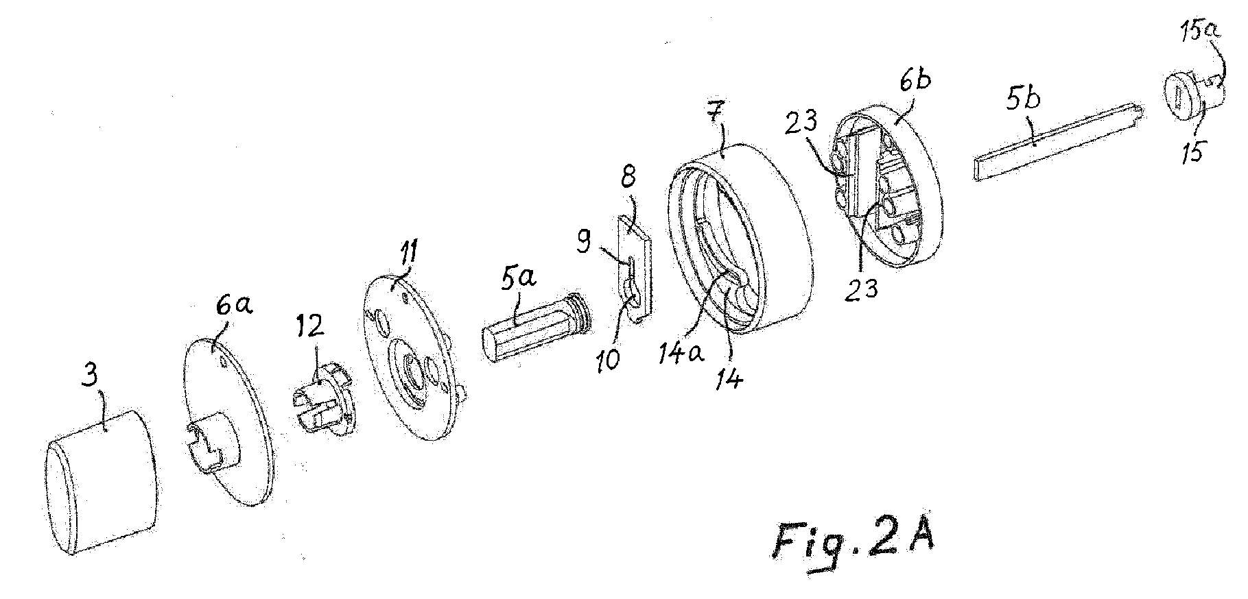
- the two-part rotary spindle 5a, 5b shown in Figs. 2A and 2B is between the rotary knob 3 and the lock mechanism 30 and extends through the accessory 6.
- the rotary spindle 5a, 5b is in engagement with the lock mechanism 30 and extends into the rotary knob 3.
- the handles are designated with reference numeral 37, and with reference numeral 39 the trigger bolt, which as the door closes triggers the lock bolt 38 into the dead-bolted position, when the pin 35 is in the upper position.
- An accessory 6 according to the invention is installed between the rotary knob 3 and the lock body 2.
- the rear casing 6b of the accessory 6 is against the surface of the door 1.
- the safety latch 8 is to be moved from a security locking release position into a security locking position, in which the flat spindle part 5b of the rotary spindle 5a, 5b is located in the slot 9 of the safety latch 8 and thus prevents the rotational movement of the rotary spindle 5a, 5b.
- the spindle part 5b is able to rotate freely in the hole 10 of the safety latch 8.
- Fig. 3 shows the lock mechanism parts essential for the invention. They are the first rotary ring 16, with which the spindle head 15 is in engagement, and the second rotary ring 17, with which the second rotary spindle 25 to be rotated by a key, is in engagement, as well as the bolt shifter 18, which is shifted by the first and second rotary rings 16, 17 as they rotate. Both rotary rings 16 and 17 have hourglass-shaped openings, with which the heads of the rotary spindles 5a, 5b and 25 are in engagement.
- the spindle head 15 of the rotary spindle 5a, 5b is in engagement with the first rotary ring 16.
- the extension part 15a of the spindle head 15 is dimensioned and shaped to extend through the first rotary ring 16 into engagement also with the second rotary ring 17, wherein, as the first rotary spindle 5a, 5b is being locked as non-rotatable in the security locking position of the safety latch 8, the extension part 15a of the spindle head 15 also prevents the second rotary ring 17 from rotating by means of the second rotary spindle 25.
- the engagement is form-locked in the direction of rotation.
- the extension part 15a is an arch, the ends of which rest against the narrowings 17a of the opening of the second rotary ring 17, which narrow the otherwise round opening into the shape of an hourglass.
- Both rotary rings 16 and 17 have thus hourglass-shaped openings ( Figs. 3 and 4 ), with which the heads of the rotary spindles 5a, 5b and 25 engage in order to rotate the rotary rings.
- the rotary spindle 5a, 5b is divided into two parts 5a and 5b.
- the bar-like part 5a is fitted non-rotationally into the rotary knob 3 and the flat part 5b is equipped with the spindle head 15 and its extension part 15a and functions in cooperation with the safety latch 8.
- the bolt shifter 18 is plate-like and has on both of its sides separate rotary rings 16 and 17 one upon the other.
- the second rotary ring 17 engages with the rotary spindle 25 to be rotated by a key.
- the bolt shifter 18 can be moved both by the key as well as by the rotary knob.
- the lock mechanism 30 must be in the dead-bolted position, i.e. in the so-called night position (the pin 35 in the upper position).
- the parts shown in Figs. 2A and 2B are assembled for a compact package.
- the safety latch 8 is a plate-like slide, the transfer mechanism 7, 8a, 14, 14a of which contains an annular turner 7, by the turning back and forth of which the safety latch 8 is to be moved back and forth (up and down in the figure) between the security locking position and the security locking release position.
- the turner 7 there is inside the turner 7 a lug 14 with a groove 14a equipped with a rising spiral, with which groove the peg 8a of the safety latch 8 is in engagement.
- the rear casing 6b has sliding guides 23, which limit the reception space of the safety latch 8, in which the safety latch is able to move.
- sliding guides 13 limit the reception space of the safety latch 8.
- cover plate 11 On top of the front casing 6a is placed the cover plate 11, which is attached to the front casing with a retainer 12.
- the retainer 12 is of plastic and all the other parts are of a metal, such as zinc and stainless steel, suitable for this purpose.
- the rear casing 6b is attached by screws to the front casing.
- Sleeve-like spacer bulges between the casings keep the casings 6a and 6b at a suitable distance from each other.
- the turner 7 remains rotatable around the edges of the casings 6a and 6b. In this case, the safety latch 8 is to be moved back and forth in its longitudinal direction as the turner 7 is turned back and forth.
- the spindle head 15 extends through the first rotary ring 16 into the opening of the second rotary ring 17, with which it engages in a form-locked manner and thus prevents the movements of both rotary rings 16 and 17 and the bolt shifter 18.
- the lock cannot be opened with a key or a picklock, because the bolt shifter 18 also cannot be moved by the rotary spindle 25 outside the door.
- Coloured indicators can indicate to a user in the room whether the security locking is on or not. These indicators can also be generated with LED lights if the accessory is equipped with a battery or a power supply. If the accessory is equipped with a battery or a power supply, the safety latch 8 manoeuvring can be arranged using an electrical drive, such as a servo, a solenoid or a motor. In this case, the safety latch 8 manoeuvring can be controlled wirelessly using a remote control device, such as a smartphone.
- the transfer mechanism described above can be replaced by a simpler mechanism, with which the back and forth movement of the safety latch 8 is achieved.
- the transfer mechanism may be just a solenoid and, for manual use, a button or a lever, which is moved by a finger back and forth. The required movement distance is quite small and movement of the light safety latch requires only a little energy.
- An accessory according to the invention can be applied particularly to locks used in the exterior doors of apartments, multi-storey apartment doors, or patio doors.
- the possibility of mechanically manipulating the safety latch from outside the door must be completely precluded.
- the mechanical manoeuvring means of the safety latch can only be mechanically manipulated from inside the door. From outside the door, however, it is possible to allow the manipulation of the electrically operated safety latch 8 of the accessory controlled by a safety code.
Landscapes
- Engineering & Computer Science (AREA)
- Structural Engineering (AREA)
- Mechanical Engineering (AREA)
- Lock And Its Accessories (AREA)
Abstract
Description
- The invention relates to an accessory for security locking of a lock, said accessory enabling the locking of the door lock such that the lock cannot be opened with a key or a picklock, the lock including a lock body, a lock mechanism inside the lock body for moving the lock bolt, a rotary knob, a key cylinder and a first rotary spindle, which is between the rotary knob and the lock mechanism and the spindle head of which is in engagement with the lock mechanism, the accessory further containing a safety latch and a transfer mechanism, by which the safety latch is to be transferred from a security locking release position into a security locking position, the lock mechanism including a first rotary ring, with which the spindle head is in engagement, and a second rotary ring, with which the second rotary spindle to be rotated by a key is in engagement, as well as a bolt shifter, which is shifted by the first and second rotary rings as they rotate.
- The international patent application of the applicant,
WO201402832 - The object of this invention is to further develop said accessory such that it is now better adapted for certain types of lock mechanisms. These types are particularly such lock mechanisms, in which the rotary spindles to be rotated by a key and a rotary knob function independently of each other.
- This object is achieved in the invention on the basis of the characterizing features presented in the accompanying
claim 1. Preferred embodiments of the invention are presented in the dependent claims. - In the following, one embodiment of the invention is described in more detail by means of reference to the accompanying figures, in which
- Fig. 1
- shows a lock equipped with an accessory according to the invention in a view along the plane of the door,
- Figs. 2A and 2B
- show an accessory according to the invention in exploded views,
- Fig. 3
- shows a view of the upper part of a lock equipped with an accessory according to the invention, as seen from outside the door, and
- Fig. 4
- shows the cooperation between the parts contained in the lock mechanism and their mutual positions.
- Embedded in a
door 1 seen inFig. 1 is alock body 2 containing aconventional lock mechanism 30, which translates the rotational movements of the key androtary knob 3 into movements of thebolt 38. Therotary knob 3 and thekey cylinder 4 are on opposite sides of the door and the lock body. The two-partrotary spindle Figs. 2A and2B is between therotary knob 3 and thelock mechanism 30 and extends through theaccessory 6. Therotary spindle lock mechanism 30 and extends into therotary knob 3. The handles are designated withreference numeral 37, and withreference numeral 39 the trigger bolt, which as the door closes triggers thelock bolt 38 into the dead-bolted position, when thepin 35 is in the upper position. - An
accessory 6 according to the invention is installed between therotary knob 3 and thelock body 2. In the present case, therear casing 6b of theaccessory 6 is against the surface of thedoor 1. Thesafety latch 8 is to be moved from a security locking release position into a security locking position, in which theflat spindle part 5b of therotary spindle slot 9 of thesafety latch 8 and thus prevents the rotational movement of therotary spindle spindle part 5b is able to rotate freely in thehole 10 of thesafety latch 8. -
Fig. 3 shows the lock mechanism parts essential for the invention. They are the firstrotary ring 16, with which thespindle head 15 is in engagement, and the secondrotary ring 17, with which the secondrotary spindle 25 to be rotated by a key, is in engagement, as well as thebolt shifter 18, which is shifted by the first and secondrotary rings rotary rings rotary spindles - The
spindle head 15 of therotary spindle rotary ring 16. Theextension part 15a of thespindle head 15 is dimensioned and shaped to extend through the firstrotary ring 16 into engagement also with the secondrotary ring 17, wherein, as the firstrotary spindle safety latch 8, theextension part 15a of thespindle head 15 also prevents the secondrotary ring 17 from rotating by means of the secondrotary spindle 25. The engagement is form-locked in the direction of rotation. For this reason, theextension part 15a is an arch, the ends of which rest against thenarrowings 17a of the opening of the secondrotary ring 17, which narrow the otherwise round opening into the shape of an hourglass. Bothrotary rings Figs. 3 and 4 ), with which the heads of therotary spindles rotary spindle parts like part 5a is fitted non-rotationally into therotary knob 3 and theflat part 5b is equipped with thespindle head 15 and itsextension part 15a and functions in cooperation with thesafety latch 8. - The
bolt shifter 18 is plate-like and has on both of its sidesseparate rotary rings rotary ring 17 engages with therotary spindle 25 to be rotated by a key. Thus, thebolt shifter 18 can be moved both by the key as well as by the rotary knob. When the invention is used, thelock mechanism 30 must be in the dead-bolted position, i.e. in the so-called night position (thepin 35 in the upper position). - The parts shown in
Figs. 2A and2B are assembled for a compact package. Thesafety latch 8 is a plate-like slide, thetransfer mechanism annular turner 7, by the turning back and forth of which thesafety latch 8 is to be moved back and forth (up and down in the figure) between the security locking position and the security locking release position. For the purpose of this moving, there is inside the turner 7 alug 14 with agroove 14a equipped with a rising spiral, with which groove the peg 8a of thesafety latch 8 is in engagement. Therear casing 6b has slidingguides 23, which limit the reception space of thesafety latch 8, in which the safety latch is able to move. On the side of thefront casing 6a, slidingguides 13 limit the reception space of thesafety latch 8. On top of thefront casing 6a is placed thecover plate 11, which is attached to the front casing with aretainer 12. Theretainer 12 is of plastic and all the other parts are of a metal, such as zinc and stainless steel, suitable for this purpose. - The
rear casing 6b is attached by screws to the front casing. Sleeve-like spacer bulges between the casings keep thecasings turner 7 remains rotatable around the edges of thecasings safety latch 8 is to be moved back and forth in its longitudinal direction as theturner 7 is turned back and forth. - As is seen from
Figs. 3 and 4 , thespindle head 15 extends through the firstrotary ring 16 into the opening of the secondrotary ring 17, with which it engages in a form-locked manner and thus prevents the movements of bothrotary rings bolt shifter 18. In this case, the lock cannot be opened with a key or a picklock, because thebolt shifter 18 also cannot be moved by therotary spindle 25 outside the door. - Coloured indicators (for example, red and green) can indicate to a user in the room whether the security locking is on or not. These indicators can also be generated with LED lights if the accessory is equipped with a battery or a power supply. If the accessory is equipped with a battery or a power supply, the
safety latch 8 manoeuvring can be arranged using an electrical drive, such as a servo, a solenoid or a motor. In this case, thesafety latch 8 manoeuvring can be controlled wirelessly using a remote control device, such as a smartphone. The transfer mechanism described above can be replaced by a simpler mechanism, with which the back and forth movement of thesafety latch 8 is achieved. The transfer mechanism may be just a solenoid and, for manual use, a button or a lever, which is moved by a finger back and forth. The required movement distance is quite small and movement of the light safety latch requires only a little energy. - An accessory according to the invention can be applied particularly to locks used in the exterior doors of apartments, multi-storey apartment doors, or patio doors. In this case, the possibility of mechanically manipulating the safety latch from outside the door must be completely precluded. In other words, the mechanical manoeuvring means of the safety latch can only be mechanically manipulated from inside the door. From outside the door, however, it is possible to allow the manipulation of the electrically operated
safety latch 8 of the accessory controlled by a safety code.
Claims (5)
- An accessory for security locking of a lock, said accessory enabling the locking of the door lock such that the lock cannot be opened with a key or a picklock, the lock including a lock body (2), a lock mechanism (30) inside the lock body for moving the lock bolt (38), a rotary knob (3), a key cylinder (4) and a first rotary spindle (5a, 5b), which is between the rotary knob (3) and the lock mechanism (30) and the spindle head (15) of which is in engagement with the lock mechanism (30), the accessory further containing a safety latch (8) and a transfer mechanism (7, 8a, 14, 14a), by which the safety latch (8) is to be transferred from a security locking release position into a security locking position, the lock mechanism (30) including a first rotary ring (16), with which the spindle head (15) is in engagement, and a second rotary ring (17), with which the second rotary spindle (25) to be rotated by a key is in engagement, as well as a bolt shifter (18), which is shifted by the first and second rotary rings (16, 17) as they rotate, characterized in that the spindle head (15) is equipped with an extension part (15a), which is dimensioned and shaped to extend through the first rotary ring (16) into engagement with the second rotary ring (17), wherein, as the first rotary spindle (5a 5b) is being locked as non-rotatable in the security locking position of the safety latch (8), the extension part (15a) of the spindle head (15) prevents the second rotary ring (17) from rotating by means of the second rotary spindle (25).
- An accessory according to claim 1, characterized in that the accessory (6) is on the interior side of the door (1) between the rotary knob (3) and the lock body (2) and the first rotary spindle (5a, 5b) extends through the accessory (6).
- An accessory according to claim 1 or 2, characterized in that the spindle head (15) is fitted into the hourglass-shaped openings of the rotary rings (16, 17).
- An accessory according to any one of claims 1-3, characterized in that the safety latch (8) is a plate-like slide, which has a hole (10) and a slot (9), and the first rotary spindle (5a, 5b) has a flat part (5b), which extends through the hole (10) when the safety latch (8) is in the security locking release position and through the slot (9) when the safety latch (8) is in the security locking position.
- An accessory according to any one of claims 1-4, characterized in that the transfer mechanism (7, 8a, 14, 14a) includes a turner (7), by the turning back and forth of which the safety latch (8) is to be moved back and forth between the security locking position and the security locking release position.
Applications Claiming Priority (1)
| Application Number | Priority Date | Filing Date | Title |
|---|---|---|---|
| FI20165770A FI127891B (en) | 2016-10-11 | 2016-10-11 | Lock with accessory lock for locking |
Publications (2)
| Publication Number | Publication Date |
|---|---|
| EP3309329A1 true EP3309329A1 (en) | 2018-04-18 |
| EP3309329B1 EP3309329B1 (en) | 2020-12-16 |
Family
ID=59997266
Family Applications (1)
| Application Number | Title | Priority Date | Filing Date |
|---|---|---|---|
| EP17194107.3A Not-in-force EP3309329B1 (en) | 2016-10-11 | 2017-09-29 | A lock comprising an accessory for security locking of said lock |
Country Status (3)
| Country | Link |
|---|---|
| EP (1) | EP3309329B1 (en) |
| FI (1) | FI127891B (en) |
| RU (1) | RU2017134155A (en) |
Citations (5)
| Publication number | Priority date | Publication date | Assignee | Title |
|---|---|---|---|---|
| US3095724A (en) * | 1961-11-06 | 1963-07-02 | Theodore Bargman Co | Door lock |
| GB2206920A (en) * | 1987-06-05 | 1989-01-18 | Laidlaw Thomson Group Plc | Door lock structure |
| US5909919A (en) * | 1997-10-07 | 1999-06-08 | Taiwan Fu Hsing Industry Co., Ltd. | Auxiliary lock assembly with additional interior locking |
| WO2011160188A1 (en) * | 2010-06-24 | 2011-12-29 | Assa Abloy Australia Pty Limited | Mortice lock actuator |
| WO2014202832A1 (en) * | 2013-06-19 | 2014-12-24 | Oviku Oy | Accessory for security locking of a lock |
-
2016
- 2016-10-11 FI FI20165770A patent/FI127891B/en not_active IP Right Cessation
-
2017
- 2017-09-29 EP EP17194107.3A patent/EP3309329B1/en not_active Not-in-force
- 2017-10-03 RU RU2017134155A patent/RU2017134155A/en not_active Application Discontinuation
Patent Citations (5)
| Publication number | Priority date | Publication date | Assignee | Title |
|---|---|---|---|---|
| US3095724A (en) * | 1961-11-06 | 1963-07-02 | Theodore Bargman Co | Door lock |
| GB2206920A (en) * | 1987-06-05 | 1989-01-18 | Laidlaw Thomson Group Plc | Door lock structure |
| US5909919A (en) * | 1997-10-07 | 1999-06-08 | Taiwan Fu Hsing Industry Co., Ltd. | Auxiliary lock assembly with additional interior locking |
| WO2011160188A1 (en) * | 2010-06-24 | 2011-12-29 | Assa Abloy Australia Pty Limited | Mortice lock actuator |
| WO2014202832A1 (en) * | 2013-06-19 | 2014-12-24 | Oviku Oy | Accessory for security locking of a lock |
Also Published As
| Publication number | Publication date |
|---|---|
| FI127891B (en) | 2019-04-30 |
| FI20165770A7 (en) | 2018-04-12 |
| RU2017134155A (en) | 2019-04-03 |
| EP3309329B1 (en) | 2020-12-16 |
Similar Documents
| Publication | Publication Date | Title |
|---|---|---|
| US11680424B2 (en) | Lock | |
| US10329795B2 (en) | Lock | |
| US10851563B1 (en) | Combination lock with electronic override key | |
| US7946141B2 (en) | Self-scrambling combination lock | |
| US20170130482A1 (en) | Accessory for security locking of a lock | |
| CN209620853U (en) | Lockable enclosure with combination locking mechanism | |
| US8495899B2 (en) | Electromechanical lock | |
| US20020166354A1 (en) | Dual cylinder deadbolt adjunct | |
| CN100557176C (en) | door locking mechanism | |
| US20220259893A1 (en) | Lock | |
| US9797161B2 (en) | Security door lock | |
| EP3309329B1 (en) | A lock comprising an accessory for security locking of said lock | |
| CN109642436B (en) | Lock with a locking mechanism | |
| US20080105010A1 (en) | Door lock assembly having a cam associated with a handle to transmit movements to a latch operating spindle | |
| AU2011224106B2 (en) | Powered latch assembly | |
| US20090090149A1 (en) | Combination lock | |
| KR200423328Y1 (en) | Mortis device with panic function | |
| GB2389141A (en) | A lockable handle assembly | |
| CA2743681C (en) | Lock | |
| EP3126596B1 (en) | Electric lock | |
| PH12020550574A1 (en) | A multi-function smart ignition lock for vehicles | |
| NZ548965A (en) | Combination deadbolt | |
| RU2194141C2 (en) | Coded lock | |
| RU2672844C1 (en) | Safe | |
| US20200131800A1 (en) | Security door lock |
Legal Events
| Date | Code | Title | Description |
|---|---|---|---|
| PUAI | Public reference made under article 153(3) epc to a published international application that has entered the european phase |
Free format text: ORIGINAL CODE: 0009012 |
|
| STAA | Information on the status of an ep patent application or granted ep patent |
Free format text: STATUS: THE APPLICATION HAS BEEN PUBLISHED |
|
| AK | Designated contracting states |
Kind code of ref document: A1 Designated state(s): AL AT BE BG CH CY CZ DE DK EE ES FI FR GB GR HR HU IE IS IT LI LT LU LV MC MK MT NL NO PL PT RO RS SE SI SK SM TR |
|
| AX | Request for extension of the european patent |
Extension state: BA ME |
|
| STAA | Information on the status of an ep patent application or granted ep patent |
Free format text: STATUS: REQUEST FOR EXAMINATION WAS MADE |
|
| 17P | Request for examination filed |
Effective date: 20181018 |
|
| RBV | Designated contracting states (corrected) |
Designated state(s): AL AT BE BG CH CY CZ DE DK EE ES FI FR GB GR HR HU IE IS IT LI LT LU LV MC MK MT NL NO PL PT RO RS SE SI SK SM TR |
|
| GRAP | Despatch of communication of intention to grant a patent |
Free format text: ORIGINAL CODE: EPIDOSNIGR1 |
|
| STAA | Information on the status of an ep patent application or granted ep patent |
Free format text: STATUS: GRANT OF PATENT IS INTENDED |
|
| RIC1 | Information provided on ipc code assigned before grant |
Ipc: E05B 47/00 20060101ALN20191212BHEP Ipc: E05B 41/00 20060101ALN20191212BHEP Ipc: E05B 63/16 20060101ALN20191212BHEP Ipc: E05B 47/06 20060101ALN20191212BHEP Ipc: E05B 13/00 20060101AFI20191212BHEP |
|
| INTG | Intention to grant announced |
Effective date: 20200114 |
|
| RAP1 | Party data changed (applicant data changed or rights of an application transferred) |
Owner name: OVIKU OY |
|
| GRAS | Grant fee paid |
Free format text: ORIGINAL CODE: EPIDOSNIGR3 |
|
| GRAA | (expected) grant |
Free format text: ORIGINAL CODE: 0009210 |
|
| STAA | Information on the status of an ep patent application or granted ep patent |
Free format text: STATUS: THE PATENT HAS BEEN GRANTED |
|
| AK | Designated contracting states |
Kind code of ref document: B1 Designated state(s): AL AT BE BG CH CY CZ DE DK EE ES FI FR GB GR HR HU IE IS IT LI LT LU LV MC MK MT NL NO PL PT RO RS SE SI SK SM TR |
|
| REG | Reference to a national code |
Ref country code: GB Ref legal event code: FG4D |
|
| REG | Reference to a national code |
Ref country code: IE Ref legal event code: FG4D |
|
| REG | Reference to a national code |
Ref country code: DE Ref legal event code: R096 Ref document number: 602017029536 Country of ref document: DE |
|
| REG | Reference to a national code |
Ref country code: AT Ref legal event code: REF Ref document number: 1345737 Country of ref document: AT Kind code of ref document: T Effective date: 20210115 |
|
| PG25 | Lapsed in a contracting state [announced via postgrant information from national office to epo] |
Ref country code: GR Free format text: LAPSE BECAUSE OF FAILURE TO SUBMIT A TRANSLATION OF THE DESCRIPTION OR TO PAY THE FEE WITHIN THE PRESCRIBED TIME-LIMIT Effective date: 20210317 Ref country code: FI Free format text: LAPSE BECAUSE OF FAILURE TO SUBMIT A TRANSLATION OF THE DESCRIPTION OR TO PAY THE FEE WITHIN THE PRESCRIBED TIME-LIMIT Effective date: 20201216 Ref country code: NO Free format text: LAPSE BECAUSE OF FAILURE TO SUBMIT A TRANSLATION OF THE DESCRIPTION OR TO PAY THE FEE WITHIN THE PRESCRIBED TIME-LIMIT Effective date: 20210316 Ref country code: RS Free format text: LAPSE BECAUSE OF FAILURE TO SUBMIT A TRANSLATION OF THE DESCRIPTION OR TO PAY THE FEE WITHIN THE PRESCRIBED TIME-LIMIT Effective date: 20201216 |
|
| REG | Reference to a national code |
Ref country code: AT Ref legal event code: MK05 Ref document number: 1345737 Country of ref document: AT Kind code of ref document: T Effective date: 20201216 |
|
| REG | Reference to a national code |
Ref country code: NL Ref legal event code: MP Effective date: 20201216 |
|
| PG25 | Lapsed in a contracting state [announced via postgrant information from national office to epo] |
Ref country code: SE Free format text: LAPSE BECAUSE OF FAILURE TO SUBMIT A TRANSLATION OF THE DESCRIPTION OR TO PAY THE FEE WITHIN THE PRESCRIBED TIME-LIMIT Effective date: 20201216 Ref country code: BG Free format text: LAPSE BECAUSE OF FAILURE TO SUBMIT A TRANSLATION OF THE DESCRIPTION OR TO PAY THE FEE WITHIN THE PRESCRIBED TIME-LIMIT Effective date: 20210316 Ref country code: LV Free format text: LAPSE BECAUSE OF FAILURE TO SUBMIT A TRANSLATION OF THE DESCRIPTION OR TO PAY THE FEE WITHIN THE PRESCRIBED TIME-LIMIT Effective date: 20201216 |
|
| PG25 | Lapsed in a contracting state [announced via postgrant information from national office to epo] |
Ref country code: NL Free format text: LAPSE BECAUSE OF FAILURE TO SUBMIT A TRANSLATION OF THE DESCRIPTION OR TO PAY THE FEE WITHIN THE PRESCRIBED TIME-LIMIT Effective date: 20201216 Ref country code: HR Free format text: LAPSE BECAUSE OF FAILURE TO SUBMIT A TRANSLATION OF THE DESCRIPTION OR TO PAY THE FEE WITHIN THE PRESCRIBED TIME-LIMIT Effective date: 20201216 |
|
| REG | Reference to a national code |
Ref country code: LT Ref legal event code: MG9D |
|
| PG25 | Lapsed in a contracting state [announced via postgrant information from national office to epo] |
Ref country code: PT Free format text: LAPSE BECAUSE OF FAILURE TO SUBMIT A TRANSLATION OF THE DESCRIPTION OR TO PAY THE FEE WITHIN THE PRESCRIBED TIME-LIMIT Effective date: 20210416 Ref country code: RO Free format text: LAPSE BECAUSE OF FAILURE TO SUBMIT A TRANSLATION OF THE DESCRIPTION OR TO PAY THE FEE WITHIN THE PRESCRIBED TIME-LIMIT Effective date: 20201216 Ref country code: SK Free format text: LAPSE BECAUSE OF FAILURE TO SUBMIT A TRANSLATION OF THE DESCRIPTION OR TO PAY THE FEE WITHIN THE PRESCRIBED TIME-LIMIT Effective date: 20201216 Ref country code: SM Free format text: LAPSE BECAUSE OF FAILURE TO SUBMIT A TRANSLATION OF THE DESCRIPTION OR TO PAY THE FEE WITHIN THE PRESCRIBED TIME-LIMIT Effective date: 20201216 Ref country code: CZ Free format text: LAPSE BECAUSE OF FAILURE TO SUBMIT A TRANSLATION OF THE DESCRIPTION OR TO PAY THE FEE WITHIN THE PRESCRIBED TIME-LIMIT Effective date: 20201216 Ref country code: EE Free format text: LAPSE BECAUSE OF FAILURE TO SUBMIT A TRANSLATION OF THE DESCRIPTION OR TO PAY THE FEE WITHIN THE PRESCRIBED TIME-LIMIT Effective date: 20201216 Ref country code: LT Free format text: LAPSE BECAUSE OF FAILURE TO SUBMIT A TRANSLATION OF THE DESCRIPTION OR TO PAY THE FEE WITHIN THE PRESCRIBED TIME-LIMIT Effective date: 20201216 |
|
| PG25 | Lapsed in a contracting state [announced via postgrant information from national office to epo] |
Ref country code: PL Free format text: LAPSE BECAUSE OF FAILURE TO SUBMIT A TRANSLATION OF THE DESCRIPTION OR TO PAY THE FEE WITHIN THE PRESCRIBED TIME-LIMIT Effective date: 20201216 Ref country code: AT Free format text: LAPSE BECAUSE OF FAILURE TO SUBMIT A TRANSLATION OF THE DESCRIPTION OR TO PAY THE FEE WITHIN THE PRESCRIBED TIME-LIMIT Effective date: 20201216 |
|
| REG | Reference to a national code |
Ref country code: DE Ref legal event code: R097 Ref document number: 602017029536 Country of ref document: DE |
|
| PG25 | Lapsed in a contracting state [announced via postgrant information from national office to epo] |
Ref country code: IS Free format text: LAPSE BECAUSE OF FAILURE TO SUBMIT A TRANSLATION OF THE DESCRIPTION OR TO PAY THE FEE WITHIN THE PRESCRIBED TIME-LIMIT Effective date: 20210416 |
|
| PLBE | No opposition filed within time limit |
Free format text: ORIGINAL CODE: 0009261 |
|
| STAA | Information on the status of an ep patent application or granted ep patent |
Free format text: STATUS: NO OPPOSITION FILED WITHIN TIME LIMIT |
|
| PG25 | Lapsed in a contracting state [announced via postgrant information from national office to epo] |
Ref country code: AL Free format text: LAPSE BECAUSE OF FAILURE TO SUBMIT A TRANSLATION OF THE DESCRIPTION OR TO PAY THE FEE WITHIN THE PRESCRIBED TIME-LIMIT Effective date: 20201216 Ref country code: IT Free format text: LAPSE BECAUSE OF FAILURE TO SUBMIT A TRANSLATION OF THE DESCRIPTION OR TO PAY THE FEE WITHIN THE PRESCRIBED TIME-LIMIT Effective date: 20201216 |
|
| 26N | No opposition filed |
Effective date: 20210917 |
|
| PG25 | Lapsed in a contracting state [announced via postgrant information from national office to epo] |
Ref country code: DK Free format text: LAPSE BECAUSE OF FAILURE TO SUBMIT A TRANSLATION OF THE DESCRIPTION OR TO PAY THE FEE WITHIN THE PRESCRIBED TIME-LIMIT Effective date: 20201216 |
|
| PG25 | Lapsed in a contracting state [announced via postgrant information from national office to epo] |
Ref country code: ES Free format text: LAPSE BECAUSE OF FAILURE TO SUBMIT A TRANSLATION OF THE DESCRIPTION OR TO PAY THE FEE WITHIN THE PRESCRIBED TIME-LIMIT Effective date: 20201216 |
|
| PG25 | Lapsed in a contracting state [announced via postgrant information from national office to epo] |
Ref country code: SI Free format text: LAPSE BECAUSE OF FAILURE TO SUBMIT A TRANSLATION OF THE DESCRIPTION OR TO PAY THE FEE WITHIN THE PRESCRIBED TIME-LIMIT Effective date: 20201216 |
|
| REG | Reference to a national code |
Ref country code: DE Ref legal event code: R119 Ref document number: 602017029536 Country of ref document: DE |
|
| REG | Reference to a national code |
Ref country code: CH Ref legal event code: PL |
|
| REG | Reference to a national code |
Ref country code: BE Ref legal event code: MM Effective date: 20210930 |
|
| GBPC | Gb: european patent ceased through non-payment of renewal fee |
Effective date: 20210929 |
|
| PG25 | Lapsed in a contracting state [announced via postgrant information from national office to epo] |
Ref country code: IS Free format text: LAPSE BECAUSE OF FAILURE TO SUBMIT A TRANSLATION OF THE DESCRIPTION OR TO PAY THE FEE WITHIN THE PRESCRIBED TIME-LIMIT Effective date: 20210416 Ref country code: MC Free format text: LAPSE BECAUSE OF FAILURE TO SUBMIT A TRANSLATION OF THE DESCRIPTION OR TO PAY THE FEE WITHIN THE PRESCRIBED TIME-LIMIT Effective date: 20201216 |
|
| PG25 | Lapsed in a contracting state [announced via postgrant information from national office to epo] |
Ref country code: LU Free format text: LAPSE BECAUSE OF NON-PAYMENT OF DUE FEES Effective date: 20210929 Ref country code: IE Free format text: LAPSE BECAUSE OF NON-PAYMENT OF DUE FEES Effective date: 20210929 Ref country code: GB Free format text: LAPSE BECAUSE OF NON-PAYMENT OF DUE FEES Effective date: 20210929 Ref country code: FR Free format text: LAPSE BECAUSE OF NON-PAYMENT OF DUE FEES Effective date: 20210930 Ref country code: DE Free format text: LAPSE BECAUSE OF NON-PAYMENT OF DUE FEES Effective date: 20220401 Ref country code: BE Free format text: LAPSE BECAUSE OF NON-PAYMENT OF DUE FEES Effective date: 20210930 |
|
| PG25 | Lapsed in a contracting state [announced via postgrant information from national office to epo] |
Ref country code: LI Free format text: LAPSE BECAUSE OF NON-PAYMENT OF DUE FEES Effective date: 20210930 Ref country code: CH Free format text: LAPSE BECAUSE OF NON-PAYMENT OF DUE FEES Effective date: 20210930 |
|
| PG25 | Lapsed in a contracting state [announced via postgrant information from national office to epo] |
Ref country code: HU Free format text: LAPSE BECAUSE OF FAILURE TO SUBMIT A TRANSLATION OF THE DESCRIPTION OR TO PAY THE FEE WITHIN THE PRESCRIBED TIME-LIMIT; INVALID AB INITIO Effective date: 20170929 |
|
| PG25 | Lapsed in a contracting state [announced via postgrant information from national office to epo] |
Ref country code: CY Free format text: LAPSE BECAUSE OF FAILURE TO SUBMIT A TRANSLATION OF THE DESCRIPTION OR TO PAY THE FEE WITHIN THE PRESCRIBED TIME-LIMIT Effective date: 20201216 |
|
| PG25 | Lapsed in a contracting state [announced via postgrant information from national office to epo] |
Ref country code: MK Free format text: LAPSE BECAUSE OF FAILURE TO SUBMIT A TRANSLATION OF THE DESCRIPTION OR TO PAY THE FEE WITHIN THE PRESCRIBED TIME-LIMIT Effective date: 20201216 |
|
| PG25 | Lapsed in a contracting state [announced via postgrant information from national office to epo] |
Ref country code: MT Free format text: LAPSE BECAUSE OF FAILURE TO SUBMIT A TRANSLATION OF THE DESCRIPTION OR TO PAY THE FEE WITHIN THE PRESCRIBED TIME-LIMIT Effective date: 20201216 |
|
| PG25 | Lapsed in a contracting state [announced via postgrant information from national office to epo] |
Ref country code: TR Free format text: LAPSE BECAUSE OF FAILURE TO SUBMIT A TRANSLATION OF THE DESCRIPTION OR TO PAY THE FEE WITHIN THE PRESCRIBED TIME-LIMIT Effective date: 20201216 |