EP3309098A1 - Carrier distributing device - Google Patents
Carrier distributing device Download PDFInfo
- Publication number
- EP3309098A1 EP3309098A1 EP17194396.2A EP17194396A EP3309098A1 EP 3309098 A1 EP3309098 A1 EP 3309098A1 EP 17194396 A EP17194396 A EP 17194396A EP 3309098 A1 EP3309098 A1 EP 3309098A1
- Authority
- EP
- European Patent Office
- Prior art keywords
- carrier
- transportation path
- orientation
- distributing
- transportation
- Prior art date
- Legal status (The legal status is an assumption and is not a legal conclusion. Google has not performed a legal analysis and makes no representation as to the accuracy of the status listed.)
- Granted
Links
- 230000008859 change Effects 0.000 claims abstract description 9
- 238000001514 detection method Methods 0.000 claims description 8
- 230000007246 mechanism Effects 0.000 claims description 5
- 238000012545 processing Methods 0.000 description 17
- 238000004804 winding Methods 0.000 description 14
- 239000007787 solid Substances 0.000 description 11
- 239000000969 carrier Substances 0.000 description 9
- 230000002093 peripheral effect Effects 0.000 description 7
- 230000032258 transport Effects 0.000 description 7
- 238000013459 approach Methods 0.000 description 5
- 238000009987 spinning Methods 0.000 description 5
- 238000003860 storage Methods 0.000 description 4
- 239000000284 extract Substances 0.000 description 3
- 238000010586 diagram Methods 0.000 description 2
- 238000007599 discharging Methods 0.000 description 2
- 238000000034 method Methods 0.000 description 2
- 238000004891 communication Methods 0.000 description 1
- 238000004519 manufacturing process Methods 0.000 description 1
- 238000012986 modification Methods 0.000 description 1
- 230000004048 modification Effects 0.000 description 1
- 230000008569 process Effects 0.000 description 1
- 238000012958 reprocessing Methods 0.000 description 1
- 238000011144 upstream manufacturing Methods 0.000 description 1
Images











Classifications
-
- B—PERFORMING OPERATIONS; TRANSPORTING
- B65—CONVEYING; PACKING; STORING; HANDLING THIN OR FILAMENTARY MATERIAL
- B65H—HANDLING THIN OR FILAMENTARY MATERIAL, e.g. SHEETS, WEBS, CABLES
- B65H67/00—Replacing or removing cores, receptacles, or completed packages at paying-out, winding, or depositing stations
- B65H67/06—Supplying cores, receptacles, or packages to, or transporting from, winding or depositing stations
- B65H67/069—Removing or fixing bobbins or cores from or on the vertical peg of trays, pallets or the pegs of a belt
-
- B—PERFORMING OPERATIONS; TRANSPORTING
- B65—CONVEYING; PACKING; STORING; HANDLING THIN OR FILAMENTARY MATERIAL
- B65H—HANDLING THIN OR FILAMENTARY MATERIAL, e.g. SHEETS, WEBS, CABLES
- B65H67/00—Replacing or removing cores, receptacles, or completed packages at paying-out, winding, or depositing stations
- B65H67/06—Supplying cores, receptacles, or packages to, or transporting from, winding or depositing stations
-
- D—TEXTILES; PAPER
- D01—NATURAL OR MAN-MADE THREADS OR FIBRES; SPINNING
- D01H—SPINNING OR TWISTING
- D01H9/00—Arrangements for replacing or removing bobbins, cores, receptacles, or completed packages at paying-out or take-up stations ; Combination of spinning-winding machine
- D01H9/18—Arrangements for replacing or removing bobbins, cores, receptacles, or completed packages at paying-out or take-up stations ; Combination of spinning-winding machine for supplying bobbins, cores, receptacles, or completed packages to, or transporting from, paying-out or take-up stations ; Arrangements to prevent unwinding of roving from roving bobbins
- D01H9/187—Arrangements for replacing or removing bobbins, cores, receptacles, or completed packages at paying-out or take-up stations ; Combination of spinning-winding machine for supplying bobbins, cores, receptacles, or completed packages to, or transporting from, paying-out or take-up stations ; Arrangements to prevent unwinding of roving from roving bobbins on individual supports, e.g. pallets
-
- B—PERFORMING OPERATIONS; TRANSPORTING
- B65—CONVEYING; PACKING; STORING; HANDLING THIN OR FILAMENTARY MATERIAL
- B65H—HANDLING THIN OR FILAMENTARY MATERIAL, e.g. SHEETS, WEBS, CABLES
- B65H2701/00—Handled material; Storage means
- B65H2701/30—Handled filamentary material
- B65H2701/31—Textiles threads or artificial strands of filaments
Definitions
- the present invention relates to a carrier distributing device that distributes a carrier used to transport a yarn supplying bobbin to two transportation paths, and particularly relates to a carrier distributing device that distributes a carrier with respect to two transportation paths extending toward two bobbin attaching units of a bobbin attaching device.
- a bobbin transporting system that attaches a bobbin wound with a yarn to a carrier, and transports the carrier attached with the bobbin to supply the bobbin to a winding unit.
- a bobbin transporting system in which a spinning machine that spins a yarn is provided adjacent to an automatic winder, and the spinning machine and the automatic winder are directly connected with a transportation path.
- a bobbin attaching device for attaching the bobbin to the carrier is arranged in the above-described bobbin transporting system.
- the transportation path of the above-described bobbin transporting system includes a branched portion provided upstream in a transporting direction of the bobbin attaching device, two parallel transportation paths provided at positions corresponding to the two bobbin attaching units, and a merging portion provided downstream in the transporting direction of the bobbin attaching device. According to such a structure, the carriers are distributed from one transportation path to two transportation paths, and then are transported toward the bobbin attaching device.
- the carriers are preferably distributed evenly to the two parallel transportation paths.
- EP 2465801 B1 only describes the arrangement of the two bobbin attaching units, and does not disclose a technique of evenly distributing the carriers to the two parallel transportation paths.
- a carrier distributing device is a device that distributes a carrier with respect to a bobbin attaching device including two bobbin attaching units, and includes a carrier transportation path and a distributing member.
- the carrier transportation path includes a carrier introducing portion, a branched portion continuing to the carrier introducing portion, a first transportation path and a second transportation path branched from the branched portion and extended toward the two bobbin attaching units, and a merging portion where the first transportation path and the second transportation path merge.
- the distributing member is a member arranged at the branched portion to distribute the carrier to the first transportation path and the second transportation path.
- the distributing member can change an orientation between a first orientation of guiding the carrier to the first transportation path and a second orientation of guiding the carrier to the second transportation path.
- the distributing member is changed from the first orientation to the second orientation by the carrier after guiding the carrier to the first transportation path, and is changed from the second orientation to the first orientation by the carrier after guiding the carrier to the second transportation path.
- the carrier is moved from the carrier introducing portion to the branched portion, and alternately, that is, evenly distributed to the first transportation path and the second transportation path by the distributing member.
- the reason for alternately distributing the carrier is because the distributing member is changed from the first orientation to the second orientation after distributing the carrier to the first transportation path, and is changed from the second orientation to the first orientation after distributing the carrier to the second transportation path.
- the orientation of the distributing member is changed by the carrier to be transported. Therefore, a member (e.g., spring, solenoid) for driving the distributing member is not necessary. In other words, the distributing operation is achieved by a simple structure.
- the distributing member may include a main body portion, a contact guiding portion, a first swing contacting portion, and a second swing contacting portion.
- the main body portion is swingable.
- the contact guiding portion is arranged on the main body portion, and makes contact with the carrier when the carrier approaches the distributing member from the carrier introducing portion, and thereafter, guides the carrier.
- the first swing contacting portion is formed on the first transportation path side with respect to the contact guiding portion in the main body portion.
- the second swing contacting portion is formed on the second transportation path side with respect to the contact guiding portion in the main body portion.
- the distributing member When the carrier is brought into contact with the second contacting portion while the carrier is moving on the second transportation path in the second orientation, the distributing member is swung to change from the second orientation to the first orientation.
- the distributing member can distribute the carrier evenly to the first transportation path and the second transportation path by simply being swung between the first orientation and the second orientation.
- the carrier may be movable to the second transportation path through the branched portion regardless of whether the distributing member is in the first orientation or the second orientation.
- a transportation guide may be formed such that a next carrier is brought into contact with the stopped carrier and is guided to move to the second transportation path.
- the carrier is guided to the second transportation path. Therefore, the transportation efficiency of the carrier at the branched portion is less likely to lower.
- the carrier distributing device may further include a first driving unit, a second driving unit, a carrier sensor, and a controller.
- the first driving unit drives the first transportation path.
- the second driving unit drives the second transportation path.
- the carrier sensor detects a state of the carrier at the merging portion.
- the controller controls the first driving unit to move backward/stop the first transportation path, and when subsequently determining that the bridge of the carrier is resolved at the merging portion according to a detection signal from the carrier sensor, the controller controls the first driving unit to moves forward the first transportation path.
- the carrier distributing device may further include a first cutout device and a second cutout device arranged on the first transportation path and the second transportation path, respectively, to continuously execute stopping and releasing of forward movement on the carrier.
- the controller cancels a cutout operation of the first cutout device and the second cutout device before backward moving/stopping the first transportation path or the second transportation path when determining that the bridge of the carrier occurred at the merging portion according to a detection signal from the carrier sensor, and starts the cutout operation of the first cutout device and the second cutout device after forward moving the first transportation path or the second transportation path.
- the cutout operation of the first cutout device and the second cutout device is canceled before the operation of resolving the bridge of the carrier at the merging portion is carried out. Therefore, a great number of carriers do not move toward the merging portion, and hence, the bridge of the carrier at the merging portion is reliably and quickly resolved.
- the distributing member is a plate-shaped piece. Therefore, a space occupied by the distributing member is small.
- a limiting mechanism that limits a swing angle of the distributing member is arranged. Therefore, the orientation of the distributing member is accurately maintained by limiting the swing angle of the distributing member.
- the contact guiding portion has a substantially triangular shape in plan view, and includes a distal end portion, a first receiving side on the first transportation path side, and a second receiving side on the second transportation path side. Therefore, the shape of the distributing member is simple.
- the carrier includes a circular column portion with a seating surface, on which the bobbin is seated, and an outer peripheral surface, to which the distributing member makes contact. Therefore, a general carrier can be used as it is.
- the carrier sensor detects whether or not a carrier is transported beyond the merging portion. Therefore, the controller can accurately determine whether the bridge of the carrier has occurred at the merging portion.
- the carriers can be evenly distributed.
- FIG. 1 is a schematic plan view of an automatic winder system including a carrier distributing device according to one standpoint of the present invention.
- the automatic winder system 101 includes an automatic winder 102, a bobbin processing device 103, and a bobbin supplying device 104.
- the automatic winder 102 is arranged on a left side of the bobbin processing device 103 in Fig. 1 .
- the bobbin processing device 103 is arranged between the bobbin supplying device 104 and the automatic winder 102.
- the automatic winder 102 includes a plurality of winding units 105.
- the winding unit 105 is a device that rewinds a spun yarn wound around a threaded bobbin tube 5B (described later) onto a different bobbin to manufacture a product package of the spun yarn.
- the bobbin processing device 103 is a device that extracts an empty bobbin tube 5A (described later) discharged by the automatic winder 102 from a carrier 3, attaches the threaded bobbin tube 5B around which a yarn, spun with a spinning machine (not illustrated) configured by winding a spun yarn generated in the spinning machine (not illustrated) around a periphery of a tubular body, is wound to the carrier 3, and supplies the threaded bobbin tube 5B toward the automatic winder 102.
- the bobbin supplying device 104 is a device that supplies the threaded bobbin tube 5B to the bobbin processing device 103.
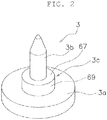
- FIG. 2 is a perspective view of a carrier.
- FIG. 3 is a perspective view of a carrier attached with a bobbin.
- the carrier 3 is a transportation body used for the transportation of the bobbin tube 5. As shown in FIG. 2 , the carrier 3 includes a disc-shaped base portion 3a and an attachment portion 3b serving as a circular column-shaped bobbin inserting portion projecting upward from the center of the upper surface of the base portion.
- the carrier 3 includes an intermediate circular column portion 3c serving as a bobbin mounting portion between the base portion 3a and the attachment portion 3b.
- the intermediate circular column portion 3c has a seating surface 67, on which the bobbin tube 5 is seated, and an outer peripheral surface 69.
- the carrier 3 transports the bobbin tube 5 in an orientation state the bobbin tube 5 is inserted to the attachment portion 3b.
- the bobbin tube 5 is a cylindrical member, on the outer peripheral surface of which the yarn is wound.
- the bobbin tube 5 is slightly tapered.
- the bobbin tube 5 When a bottom portion of the bobbin tube 5 is inserted to the attachment portion 3b of the carrier 3, the bobbin tube 5 is set in the carrier 3, as shown in FIG. 3 , to be transported with the carrier 3.
- a bobbin tube itself around which the spun yarn is not wound is referred to as an empty bobbin tube 5A, and a combination of the bobbin tube and the spun yarn wound thereon is referred to as the threaded bobbin tube 5.
- the automatic winder 102 includes a supply path 106 for transporting the threaded bobbin tube 5B to each winding unit 105.
- the automatic winder 102 also includes a collecting path 107 for transporting the empty bobbin tube 5A discharged from each winding unit 105.
- the supply path 106 and the collecting path 107 are configured by a belt conveyor, and to transport the bobbin tube 5 using the carrier 3.
- the bobbin processing device 103 includes, as a transportation means of the solid bobbin and the empty bobbin, a carrier transportation line 108 that transports such bobbins while being mounted on the carrier 3.
- the carrier transportation line 108 is connected to the supply path 106 and the collecting path 107 of the automatic winder 102.
- the carrier 3 attached with the threaded bobbin tube 5B is supplied to the winding unit 105 by the carrier transportation line 108 and the supply path 106 from the bobbin processing device 103.
- the carrier 3 attached with the empty bobbin tube 5A is returned to the bobbin processing device 103 by the collecting path 107 and the carrier transportation line 108 from the winding unit 105.
- the carrier transportation line 108 includes a main transportation line 121, and a return transportation line 122.
- the main transportation line 121 is a line for transporting the empty bobbin tube 5A discharged from the automatic winder 102, replacing the empty bobbin tube 5A with the threaded bobbin tube 5B in the middle of transportation, and transporting the threaded bobbin tube toward the automatic winder 102.
- the main transportation line 121 is formed into a substantially U-shape. A starting end of the main transportation line 121 is connected to a terminating end of the collecting path 107, and a terminating end of the main transportation line 121 is connected to a starting end of the supply path 106.
- FIG. 4 is a schematic cross-sectional view of the carrier and the carrier distributing device.
- the carrier transportation line 108 includes a guiding path 21, and a belt conveyor 23 (includes first belt conveyor 23A and second belt conveyor 23B described later) arranged below the guiding path 21.
- the carrier 3 is transported on the belt conveyor 23 according to the guiding path 21.
- the following description is similar also for the supply path 106 and the collecting path 107.
- the guiding path 21 is configured by an upper plate 25 formed with a slit.
- the belt conveyor 23 is arranged below the slit.
- the belt conveyor 23 is, for example, a flat belt or a round belt which is an endless belt.
- the carrier 3 is transported while being mounted on the belt conveyor 23.
- an orientation state in which the attachment portion 3b and the intermediate circular column portion 3c of the carrier 3 project out from the guiding path 21 is obtained.
- An outer peripheral surface 69 of the intermediate circular column portion 3c is then guided by the guiding path 21, that is, a peripheral edge of the slit, so that the carrier 3 is transported along the guiding path 21.
- a bobbin extracting device 11 and a solid bobbin supplying device 13 are arranged along the main transportation line 121.
- the bobbin extracting device 11 is a device that extracts and collects the empty bobbin tube 5A from the carrier 3.
- the solid bobbin supplying device 13 is a device that attaches the threaded bobbin tube 5B manufactured with the spinning machine to the carrier 3 in a substantially upright state .
- the threaded bobbin tube 5B is supplied from the bobbin supplying device 104 to the solid bobbin supplying device 13.
- the solid bobbin supplying device 13 includes a bobbin inserting device, a part feeder, a bobbin distributing device, and a pair of bobbin chutes (120, 121).
- the solid bobbin supplying device 13 can simultaneously supply the empty bobbin tube 5A to the carrier 3 at two places with the bobbin distributing device and the pair of bobbin chutes.
- Each bobbin chute sets the bobbin tube 5 so as to be inserted to the attachment portion 3b of the carrier 3.
- the bobbin chute includes, for example, each divided piece obtained by dividing a cone-shaped cylindrical body in two in an axial direction.
- a bunch unwinding device 15, a yarn end processing device 17, and a pick finding device 19 are arranged downstream in the transporting direction of the solid bobbin supplying device 13.
- the bunch unwinding device 15 is a device that unwinds a bunch winding of a bottom bunch wound around the threaded bobbin tube 5B.
- the yarn end processing device 17 is a device that cuts a back wind yarn wound around a yarn layer surface of the threaded bobbin tube 5B, and removes a remaining yarn side of the back wind yarn.
- the pick finding device 19 is a device that separates and finds pick of the yarn end from the surface of the threaded bobbin tube 5B, and winds the found pick of yarn end at a top of the bobbin main body to insert the yarn end to a top hole of the bobbin main body.
- the return transportation line 122 is a path for reprocessing the threaded bobbin tube 5B that, for example, failed in the pick finding process.
- the return transportation line 122 is a bypass path that connects a terminating end and a starting end of the main transportation line 121.
- a set of bunch unwinding device 15, yarn end processing device 17, and pick finding device 19 is also arranged in the return transportation line 122. The description thereof will be omitted.
- the threaded bobbin tube 5B is mounted on the empty carrier 3 in a substantially upright state.
- the carrier 3 is transported on the main transportation line 121 toward the downstream bunch unwinding device 15.
- the bunch unwinding device 15 the bottom bunch formed in the threaded bobbin tube 5B is removed.
- the threaded bobbin tube 5B is transported on the main transportation line 121 toward the yarn end processing device 17.
- the back wind yarn wound around the yarn layer surface of the threaded bobbin tube 5B is cut, and a distal end side winding portion is formed.
- the threaded bobbin tube 5B is transported on the main transportation line 121 toward the pick finding device 19.
- the distal end side winding portion is sucked upward, and inserted to the inner side of the tubular body of the threaded bobbin tube 5B.
- the threaded bobbin tube 5B is further transported downstream on the main transportation line 121, and supplied to the supply path 106 of the automatic winder 102.
- the threaded bobbin tube 5B is transported on the supply path 106, and supplied to either winding unit 105.
- the unwinding of the yarn is carried out from the threaded bobbin tube 5B, and the unwound yarn is wound into a package.
- the carrier 3 mounted with the empty bobbin tube 5A, in which the peripheral yarn are all unwound, is discharged from the winding unit 105, and again returned to the main transportation line 121 of the bobbin processing device 103 through the collecting path 107.
- the bobbin extracting device 11 extracts the empty bobbin tube 5A mounted on the carrier 3.
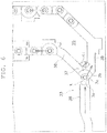
- FIGS. 5 and 6 are partial plan views showing a periphery of the branched portion.
- the carrier distributing device 31 is a part of the bobbin processing device 103 described above.
- the carrier distributing device 31 is a device that distributes the carrier 3 with respect to the solid bobbin supplying device 13 including a pair of bobbin chutes 120, 121 (one example of bobbin attaching unit).
- the carrier distributing device 31 includes a carrier transportation path 33 as a part of the main transportation line 121.
- the carrier transportation path 33 includes a carrier introducing portion 36, a branched portion 37 continuing to the carrier introducing portion 36, a first transportation path 38 and a second transportation path 39 branched from the branched portion 37 and extended in parallel toward the pair of bobbin chutes (not illustrated), and a merging portion 51 where the first transportation path 38 and the second transportation path 39 merge.
- the first transportation path 38 is a path linearly extending from the branched portion 37 to the merging portion 51.
- the carrier 3 is mainly driven by a first belt conveyor 23A (one example of first driving unit).
- the first belt conveyor 23A includes a linearly arranged flat belt.
- the first belt conveyor 23A is configured by the flat belt, a drive pulley and a driven pulley (not illustrated) wound around the flat belt, and a first drive motor 71 ( FIG. 18 ) that drives the drive pulley.
- the second transportation path 39 is a path extending on the outer side (bobbin supplying device 104 side) of the first transportation path 38 from the branched portion 37 to the merging portion 51.
- the carrier 3 is driven by the second belt conveyor 23B (one example of second driving unit) .
- the second belt conveyor 23B is a driving means that transports the carrier 3 in the majority of the main transportation line 121 and the return transportation line 122.
- the second belt conveyor 23B is configured by a round belt, a drive pulley and a plurality of driven pulleys (not illustrated) wound around the round belt, and a second drive motor 73 ( FIG. 18 ) that drives the drive pulley.
- a carrier sensor 55 is provided in the vicinity of the merging portion 51.
- the carrier sensor 55 is a proximity sensor (described later) that detects a state of the carrier at the merging portion 51.
- the carrier distributing device 31 further includes a first cutout device 59 and a second cutout device 61.
- the first cutout device 59 and the second cutout device 61 are arranged on the first transportation path 38 and the second transportation path 39, respectively, and switch the carrier 3 attached with the threaded bobbin tube 5B by the bobbin chute from the stopped state to the released state to cut out the carrier 3 one at a time at an appropriate interval.
- the carrier distributing device 31 includes a distributing member 41.
- the distributing member 41 is a member arranged on the branched portion 37 to distribute the carrier 3 to the first transportation path 38 and the second transportation path 39.
- the distributing member 41 can change the orientation between a first orientation A ( FIG. 5 ) of guiding the carrier 3 to the first transportation path 38, and a second orientation B ( FIG. 6 ) of guiding the carrier to the second transportation path 39. After guiding the carrier 3 to the first transportation path 38, the distributing member 41 is changed from the first orientation A to the second orientation B by the relevant carrier 3. Moreover, after guiding the carrier 3 to the second transportation path 39, the distributing member 41 is changed from the second orientation B to the first orientation A by the relevant carrier 3.
- the carrier 3 is moved from the carrier introducing portion 36 to the branched portion 37, and then alternately, that is, evenly distributed to the first transportation path 38 and the second transportation path 39 by the distributing member 41.
- the reason for alternately distributing the carrier is because the distributing member 41 is changed from the first orientation A to the second orientation B after distributing the carrier 3 to the first transportation path 38, and is changed from the second orientation B to the first orientation A after distributing the carrier 3 to the second transportation path 39.
- the orientation of the distributing member 41 is changed by the transported carrier 3. Therefore, a member (e.g., spring, solenoid) for driving the distributing member 41 is not necessary. That is, the distributing operation is realized with a simple structure.
- a member e.g., spring, solenoid
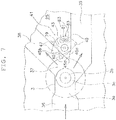
- FIG. 7 is a partial plan view showing the carrier distributing device.
- a solid line indicates the first orientation A and a dashed line indicates the second orientation B with respect to the distributing member 41.
- the distributing member 41 is a plate-shaped piece. Therefore, a space occupied by the distributing member 41 is small.
- the general carrier 3 can be used as it is.
- the distributing member 41 includes a main body portion 43, a contact guiding portion 45, a first swing contacting portion 47, and a second swing contacting portion 49.
- the main body portion 43 is swingable. Specifically, the main body portion 43 is swingably supported at a corner of the upper plate 25 sectionalizing the first transportation path 38 and the second transportation path 39 by way of a pin structure 79.
- a limiting mechanism 63 that limits a swing angle of the distributing member 41 is arranged at the corner of the upper plate 25.
- the limiting mechanism 63 includes an arc-shaped slit 81 formed in the upper plate 25, and a pin 83 extending from the distributing member 41 and moving within the slit. Therefore, the orientation of the distributing member 41 becomes accurate as the swing angle of the distributing member 41 is limited.
- the contact guiding portion 45 is arranged in the main body portion 43, and makes contact with the carrier 3 when the carrier 3 approaches the distributing member 41 from the carrier introducing portion 36, and thereafter, guides the carrier 3.
- the contact guiding portion 45 has a substantially triangular shape in plan view, and includes a distal end portion 45a, a first receiving side 45b on the first transportation path 38 side, and a second receiving side 45c on the second transportation path 39 side. Therefore, the shape of the distributing member 41 is simple.
- the first receiving side 45b faces the carrier introducing portion 36 side, as shown in FIG. 8 .
- the second receiving side 45c faces the carrier introducing portion 36 side, as shown in FIG. 12 .
- the first swing contacting portion 47 is formed on the first transportation path 38 side with respect to the contact guiding portion 45 in the main body portion 43.
- the second swing contacting portion 49 is formed on the second transportation path 39 side with respect to the contact guiding portion 45 in the main body portion 43.
- the second swing contacting portion 49 is projected out to the second transportation path 39, as shown in FIG. 12 .
- the distributing member 41 is swung to change from the first orientation A to the second orientation B. Furthermore, when the carrier 3 makes contact with the second swing contacting portion 49 as the carrier 3 is moved on the second transportation path 39 in the second orientation B, the distributing member 41 is swung to change from the second orientation B to the first orientation A.
- the distributing member 41 can distribute the carriers 3 evenly to the first transportation path 38 and the second transportation path 39 by simply swinging between the first orientation A and the second orientation B.
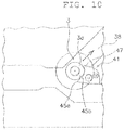
- FIGS. 8 to 11 are partial plan views showing the carrier distributing operation.
- the carrier 3 makes contact with the distributing member 41, as shown in FIG. 9 .
- the intermediate circular column portion 3c of the carrier 3 makes contact with the distal end portion 45a of the contact guiding portion 45 of the distributing member 41.
- the carrier 3 is guided by the first receiving side 45b of the contact guiding portion 45 to be moved toward the first transportation path 38.
- the carrier 3 is moved on the first transportation path 38 by the first belt conveyor 23A.
- the carrier 3 makes contact with the first swing contacting portion 47, thus swinging the distributing member 41 from the first orientation A to the second orientation B.
- FIGS. 12 to 15 are partial plan views showing the carrier distributing operation.
- the carrier 3 makes contact with the distributing member 41, as shown in FIG. 13 .
- the intermediate circular column portion 3c of the carrier 3 makes contact with the distal end portion 45a of the contact guiding portion 45 of the distributing member 41.
- the carrier 3 is guided by the second receiving side 45c of the contact guiding portion 45 to be moved toward the second transportation path 39.
- the carrier 3 is moved on the second transportation path 39 by the second belt conveyor 23B.
- the carrier 3 makes contact with the second swing contacting portion 49, thus swinging the distributing member 41 from the second orientation B to the first orientation A.
- the carrier 3 sometimes stops near the branched portion 37 when the carriers 3 are stagnated in the first transportation path 38 .
- the carrier 3 that approaches the branched portion 37 next makes contact with the stopped carrier 3 to be guided to the second transportation path 39. That is, the transportation guide (guiding path 21) is formed by the layout of the guiding path 21 so that the operations described above are executed. This is the same regardless of whether the distributing member 41 is in the first orientation A, as shown in FIG. 16 , or the distributing member 41 is in the second orientation B, as shown in FIG. 17 .
- the carrier 3 is guided to the second transportation path 39 when the carriers 3 are full and stagnated in the first transportation path 38. Therefore, the transportation efficiency of the carrier 3 at the branched portion 37 is less likely to lower.
- FIG. 18 is a block diagram showing the control configuration of the carrier distributing device.
- the carrier distributing device 31 includes a controller 57.
- the controller 57 is a computer system including a processor (e.g., CPU), a storage device (e.g., ROM, RAM, HDD, SSD, and the like), and various types of interfaces (e.g., A/D converter, D/A converter, communication interface, and the like).
- the control section carries out various control operations by executing a program stored in the storage unit (corresponds to some or all of a storage region of storage device).
- the controller 57 may be configured with a single processor, but may be configured with a plurality of processors, each being independent for each control.
- each element of the controller 57 may be realized as a program executable in the computer system configuring the control section. In addition, some of the function of each element of the controller 57 may be configured by a custom IC.
- the controller 57 is connected to the solid bobbin supplying device 13, the first drive motor 71, the second drive motor 73, the first cutout device 59, and the second cutout device 61. Therefore, the controller 57 can transmit control signals to such devices.
- the first drive motor 71 drives the first belt conveyor 23A, that is, the first transportation path 38.
- the second drive motor 73 drives the second belt conveyor 23B, that is, the second transportation path 39.
- the controller 57 is connected to the carrier sensor 55. Therefore, the controller 57 can accurately determine whether a bridge of the carrier 3 has occurred at the merging portion 51.
- the carrier sensor 55 checks the passing of the carrier 3 at a point ahead of the merging portion 51.
- controller 57 is also connected to a sensor that detects the size, shape, and position of the carrier and the bobbin, a sensor and a switch that detect the state of each device, and an information input device.
- FIG. 19 is a flowchart showing the bridge resolving control of the merging portion of the carrier distributing device.
- FIGS. 20 to 22 are partial plan views showing the bridge resolving operation at the merging portion.
- control flowchart described below is illustrative, and each step may be omitted or interchanged as necessary. Furthermore, a plurality of steps may be executed simultaneously, or some or all of the steps may be executed in an overlapping manner.
- each block of the control flowchart is not limited to a single control operation, and may be replaced with a plurality of control operations represented with a plurality of blocks.
- the carrier 3 attached with the threaded bobbin tube 5B moves on the first transportation path 38 and the second transportation path 39, and passes through the merging portion 51 to move further downstream.
- step S1 of FIG. 19 the controller 57 determines whether or not the bridge of the carrier 3 has occurred at the merging portion 51 according to the detection signal from the carrier sensor 55.
- FIG. 21 shows a state in which the bridge has occurred at the merging portion 51. That is, the carrier 3 does not move further from the merging portion 51, and a state in which the carrier 3 is not detected by the carrier sensor 55 continues. Thus, if the carrier 3 cannot be detected even after elapse of a predetermined time from the execution of the cutout of the carrier 3, the controller 57 determines that the bridge has occurred.
- step S2 the controller 57 determines whether or not the chute operation is under operating in the solid bobbin supplying device 13. If in the shoot operation is under operating, the termination of the chute operation is waited.
- step S3 the controller 57 stops the cutout operation of the first cutout device 59 and the second cutout device 61.
- step S4 the controller 57 reversely rotates the first belt conveyor 23A by reversely rotating the first drive motor 71.
- the carrier 3 on the first transportation path 38 is moved backward.
- step S5 the controller 57 stops the first belt conveyor 23A by stopping the first drive motor 71.
- the carrier 3 on the first transportation path 38 stops while being away from the merging portion 51. That is, the bridge at the merging portion 51 is resolved, and hence the carrier 3 on the second transportation path 39 is moved farther through the merging portion 51.
- step S6 the controller 57 thereafter determines whether or not the bridge of the carrier 3 is resolved at the merging portion 51 according to the detection signal from the carrier sensor 55.
- step S7 the controller 57 waits until elapse of a predetermined time. Meanwhile, the discharging of the carrier 3 on the second transportation path 39 from the merging portion 51 is completed.
- step S8 the controller 57 normally rotates the first belt conveyor 23A by normally rotating the first drive motor 71.
- the carrier 3 on the first transportation path 38 moves forward, as shown in FIG. 22 .
- step S9 the controller 57 waits until elapse of a predetermined time. Meanwhile, the discharging of the carrier 3 on the first transportation path 38 from the merging portion 51 is completed.
- step S10 the controller 57 starts the cutout operation of the first cutout device 59 and the second cutout device 61.
- the carrier 3 is moved backward/stopped on the first transportation path 38 when the bridge of the carrier 3 occurs at the merging portion 51.
- the carrier 3 on the first transportation path 38 can be moved forward by resolving the bridge of the carrier 3 at the merging portion 51.
- the bridge of the carrier 3 at the merging portion 51 is quickly resolved with a simple operation.
- a specific shape of the distributing member is changed depending on the shape of the branched portion, and is not limited to the embodiment described above.
Landscapes
- Engineering & Computer Science (AREA)
- Mechanical Engineering (AREA)
- Textile Engineering (AREA)
- Replacing, Conveying, And Pick-Finding For Filamentary Materials (AREA)
Abstract
Description
- The present invention relates to a carrier distributing device that distributes a carrier used to transport a yarn supplying bobbin to two transportation paths, and particularly relates to a carrier distributing device that distributes a carrier with respect to two transportation paths extending toward two bobbin attaching units of a bobbin attaching device.
- Conventionally, there is known a bobbin transporting system that attaches a bobbin wound with a yarn to a carrier, and transports the carrier attached with the bobbin to supply the bobbin to a winding unit. There is also known a bobbin transporting system in which a spinning machine that spins a yarn is provided adjacent to an automatic winder, and the spinning machine and the automatic winder are directly connected with a transportation path.
- A bobbin attaching device for attaching the bobbin to the carrier is arranged in the above-described bobbin transporting system.
- Furthermore, a device that enhances the processing ability by arranging two bobbin attaching units, and distributing the transported carrier to each bobbin attaching unit is proposed for the bobbin attaching device (see
EP 2465801 B1 , for example). - The transportation path of the above-described bobbin transporting system includes a branched portion provided upstream in a transporting direction of the bobbin attaching device, two parallel transportation paths provided at positions corresponding to the two bobbin attaching units, and a merging portion provided downstream in the transporting direction of the bobbin attaching device. According to such a structure, the carriers are distributed from one transportation path to two transportation paths, and then are transported toward the bobbin attaching device.
- In order to exhibit the ability of the two bobbin attaching units of the bobbin attaching device to a maximum extent, the carriers are preferably distributed evenly to the two parallel transportation paths. However,
EP 2465801 B1 only describes the arrangement of the two bobbin attaching units, and does not disclose a technique of evenly distributing the carriers to the two parallel transportation paths. - It is an object of the present invention to provide a carrier distributing device that evenly distributes a carrier used to transport a bobbin to two transportation paths.
- A plurality of aspects will be hereinafter described as a means for achieving the object. Such aspects can be arbitrarily combined as necessary.
- A carrier distributing device according to one aspect of the present invention is a device that distributes a carrier with respect to a bobbin attaching device including two bobbin attaching units, and includes a carrier transportation path and a distributing member.
- The carrier transportation path includes a carrier introducing portion, a branched portion continuing to the carrier introducing portion, a first transportation path and a second transportation path branched from the branched portion and extended toward the two bobbin attaching units, and a merging portion where the first transportation path and the second transportation path merge.
- The distributing member is a member arranged at the branched portion to distribute the carrier to the first transportation path and the second transportation path. The distributing member can change an orientation between a first orientation of guiding the carrier to the first transportation path and a second orientation of guiding the carrier to the second transportation path. The distributing member is changed from the first orientation to the second orientation by the carrier after guiding the carrier to the first transportation path, and is changed from the second orientation to the first orientation by the carrier after guiding the carrier to the second transportation path.
- In such a device, the carrier is moved from the carrier introducing portion to the branched portion, and alternately, that is, evenly distributed to the first transportation path and the second transportation path by the distributing member. The reason for alternately distributing the carrier is because the distributing member is changed from the first orientation to the second orientation after distributing the carrier to the first transportation path, and is changed from the second orientation to the first orientation after distributing the carrier to the second transportation path. Furthermore, the orientation of the distributing member is changed by the carrier to be transported. Therefore, a member (e.g., spring, solenoid) for driving the distributing member is not necessary. In other words, the distributing operation is achieved by a simple structure.
- The distributing member may include a main body portion, a contact guiding portion, a first swing contacting portion, and a second swing contacting portion.
- The main body portion is swingable.
- The contact guiding portion is arranged on the main body portion, and makes contact with the carrier when the carrier approaches the distributing member from the carrier introducing portion, and thereafter, guides the carrier.
- The first swing contacting portion is formed on the first transportation path side with respect to the contact guiding portion in the main body portion. When the carrier is brought into contact with the first contacting portion while the carrier is moving on the first transportation path in the first orientation, the distributing member is swung to change from the first orientation to the second orientation.
- The second swing contacting portion is formed on the second transportation path side with respect to the contact guiding portion in the main body portion. When the carrier is brought into contact with the second contacting portion while the carrier is moving on the second transportation path in the second orientation, the distributing member is swung to change from the second orientation to the first orientation. In this device, the distributing member can distribute the carrier evenly to the first transportation path and the second transportation path by simply being swung between the first orientation and the second orientation.
- The carrier may be movable to the second transportation path through the branched portion regardless of whether the distributing member is in the first orientation or the second orientation. When the carrier is stagnated in the first transportation path to stop in the vicinity of the branched portion, a transportation guide may be formed such that a next carrier is brought into contact with the stopped carrier and is guided to move to the second transportation path. In this device, when the carrier is stagnated in the first transportation path, the carrier is guided to the second transportation path. Therefore, the transportation efficiency of the carrier at the branched portion is less likely to lower.
- The carrier distributing device may further include a first driving unit, a second driving unit, a carrier sensor, and a controller.
- The first driving unit drives the first transportation path.
- The second driving unit drives the second transportation path.
- The carrier sensor detects a state of the carrier at the merging portion.
- When determining that a bridge of the carrier has occurred at the merging portion according to a detection signal from the carrier sensor, the controller controls the first driving unit to move backward/stop the first transportation path, and when subsequently determining that the bridge of the carrier is resolved at the merging portion according to a detection signal from the carrier sensor, the controller controls the first driving unit to moves forward the first transportation path.
- In this device, when the bridge of the carrier occurs at the merging portion, the first transportation path is moved backward/stopped. When the bridge of the carrier at the merging portion is thereafter resolved, the first transportation path is moved forward. As a result, the bridge of the carrier at the merging portion is quickly resolved with a simple operation. That is, an alarm stop time is reduced.
- The carrier distributing device may further include a first cutout device and a second cutout device arranged on the first transportation path and the second transportation path, respectively, to continuously execute stopping and releasing of forward movement on the carrier.
- The controller cancels a cutout operation of the first cutout device and the second cutout device before backward moving/stopping the first transportation path or the second transportation path when determining that the bridge of the carrier occurred at the merging portion according to a detection signal from the carrier sensor, and starts the cutout operation of the first cutout device and the second cutout device after forward moving the first transportation path or the second transportation path. In this device, the cutout operation of the first cutout device and the second cutout device is canceled before the operation of resolving the bridge of the carrier at the merging portion is carried out. Therefore, a great number of carriers do not move toward the merging portion, and hence, the bridge of the carrier at the merging portion is reliably and quickly resolved.
- According to one aspect, the distributing member is a plate-shaped piece. Therefore, a space occupied by the distributing member is small.
- According to one aspect, a limiting mechanism that limits a swing angle of the distributing member is arranged. Therefore, the orientation of the distributing member is accurately maintained by limiting the swing angle of the distributing member.
- According to one aspect, the contact guiding portion has a substantially triangular shape in plan view, and includes a distal end portion, a first receiving side on the first transportation path side, and a second receiving side on the second transportation path side. Therefore, the shape of the distributing member is simple.
- According to one aspect, the carrier includes a circular column portion with a seating surface, on which the bobbin is seated, and an outer peripheral surface, to which the distributing member makes contact. Therefore, a general carrier can be used as it is.
- According to one aspect, the carrier sensor detects whether or not a carrier is transported beyond the merging portion. Therefore, the controller can accurately determine whether the bridge of the carrier has occurred at the merging portion.
- In the carrier distributing device according to the present invention, the carriers can be evenly distributed.
-
-
FIG. 1 is a schematic plan view showing an automatic winder system including a carrier distributing device according to one aspect of the present invention; -
FIG. 2 is a perspective view showing a carrier; -
FIG. 3 is a perspective view showing the carrier attached with a bobbin; -
FIG. 4 is a schematic cross-sectional view showing the carrier and the carrier distributing device; -
FIG. 5 is a partial plan view showing a periphery of a branched portion; -
FIG. 6 is a partial plan view showing the periphery of the branched portion; -
FIG. 7 is a partial plan view showing the carrier distributing device; -
FIG. 8 is a partial plan view showing a carrier distributing operation; -
FIG. 9 is a partial plan view showing the carrier distributing operation; -
FIG. 10 is a partial plan view showing the carrier distributing operation; -
FIG. 11 is a partial plan view showing the carrier distributing operation; -
FIG. 12 is a partial plan view showing the carrier distributing operation; -
FIG. 13 is a partial plan view showing the carrier distributing operation; -
FIG. 14 is a partial plan view showing the carrier distributing operation; -
FIG. 15 is a partial plan view showing the carrier distributing operation; -
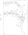
FIG. 16 is a partial plan view showing the distributing operation of when the first transportation path is jammed; -
FIG. 17 is a partial plan view showing the distributing operation of when the first transportation path is jammed; -
FIG. 18 is a block diagram showing a control configuration of the carrier distributing device; -
FIG. 19 is a flowchart showing a bridge resolving control of a merging portion of the carrier distributing device; -
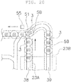
FIG. 20 is a partial plan view showing the bridge resolving operation at the merging portion; -
FIG. 21 is a partial plan view showing the bridge resolving operation at the merging portion; and -
FIG. 22 is a partial plan view showing the bridge resolving operation at the merging portion. - An
automatic winder system 101 according to one embodiment of the present invention will be described with reference toFIG. 1. FIG. 1 is a schematic plan view of an automatic winder system including a carrier distributing device according to one standpoint of the present invention. - The
automatic winder system 101 includes anautomatic winder 102, abobbin processing device 103, and abobbin supplying device 104. Theautomatic winder 102 is arranged on a left side of thebobbin processing device 103 inFig. 1 . Thebobbin processing device 103 is arranged between thebobbin supplying device 104 and theautomatic winder 102. - The
automatic winder 102 includes a plurality of windingunits 105. The windingunit 105 is a device that rewinds a spun yarn wound around a threadedbobbin tube 5B (described later) onto a different bobbin to manufacture a product package of the spun yarn. - The
bobbin processing device 103 is a device that extracts anempty bobbin tube 5A (described later) discharged by theautomatic winder 102 from acarrier 3, attaches the threadedbobbin tube 5B around which a yarn, spun with a spinning machine (not illustrated) configured by winding a spun yarn generated in the spinning machine (not illustrated) around a periphery of a tubular body, is wound to thecarrier 3, and supplies the threadedbobbin tube 5B toward theautomatic winder 102. - The
bobbin supplying device 104 is a device that supplies the threadedbobbin tube 5B to thebobbin processing device 103. - The
carrier 3 and thebobbin tube 5 will be described with reference toFIGS. 2 and3 .FIG. 2 is a perspective view of a carrier.FIG. 3 is a perspective view of a carrier attached with a bobbin. - The
carrier 3 is a transportation body used for the transportation of thebobbin tube 5. As shown inFIG. 2 , thecarrier 3 includes a disc-shapedbase portion 3a and anattachment portion 3b serving as a circular column-shaped bobbin inserting portion projecting upward from the center of the upper surface of the base portion. Thecarrier 3 includes an intermediatecircular column portion 3c serving as a bobbin mounting portion between thebase portion 3a and theattachment portion 3b. The intermediatecircular column portion 3c has aseating surface 67, on which thebobbin tube 5 is seated, and an outerperipheral surface 69. Thecarrier 3 transports thebobbin tube 5 in an orientation state thebobbin tube 5 is inserted to theattachment portion 3b. - The
bobbin tube 5 is a cylindrical member, on the outer peripheral surface of which the yarn is wound. Thebobbin tube 5 is slightly tapered. - When a bottom portion of the
bobbin tube 5 is inserted to theattachment portion 3b of thecarrier 3, thebobbin tube 5 is set in thecarrier 3, as shown inFIG. 3 , to be transported with thecarrier 3. In the following description, a bobbin tube itself around which the spun yarn is not wound is referred to as anempty bobbin tube 5A, and a combination of the bobbin tube and the spun yarn wound thereon is referred to as the threadedbobbin tube 5. - As shown in
FIG. 1 , theautomatic winder 102 includes asupply path 106 for transporting the threadedbobbin tube 5B to each windingunit 105. Theautomatic winder 102 also includes a collectingpath 107 for transporting theempty bobbin tube 5A discharged from each windingunit 105. Thesupply path 106 and the collectingpath 107 are configured by a belt conveyor, and to transport thebobbin tube 5 using thecarrier 3. - The
bobbin processing device 103 includes, as a transportation means of the solid bobbin and the empty bobbin, acarrier transportation line 108 that transports such bobbins while being mounted on thecarrier 3. Thecarrier transportation line 108 is connected to thesupply path 106 and the collectingpath 107 of theautomatic winder 102. Thecarrier 3 attached with the threadedbobbin tube 5B is supplied to the windingunit 105 by thecarrier transportation line 108 and thesupply path 106 from thebobbin processing device 103. Thecarrier 3 attached with theempty bobbin tube 5A is returned to thebobbin processing device 103 by the collectingpath 107 and thecarrier transportation line 108 from the windingunit 105. - The
carrier transportation line 108 includes amain transportation line 121, and areturn transportation line 122. - The
main transportation line 121 is a line for transporting theempty bobbin tube 5A discharged from theautomatic winder 102, replacing theempty bobbin tube 5A with the threadedbobbin tube 5B in the middle of transportation, and transporting the threaded bobbin tube toward theautomatic winder 102. Themain transportation line 121 is formed into a substantially U-shape. A starting end of themain transportation line 121 is connected to a terminating end of the collectingpath 107, and a terminating end of themain transportation line 121 is connected to a starting end of thesupply path 106. - A structure of the
carrier transportation line 108 will be described with reference toFIG. 4. FIG. 4 is a schematic cross-sectional view of the carrier and the carrier distributing device. - The
carrier transportation line 108 includes a guidingpath 21, and a belt conveyor 23 (includesfirst belt conveyor 23A andsecond belt conveyor 23B described later) arranged below the guidingpath 21. Thecarrier 3 is transported on thebelt conveyor 23 according to the guidingpath 21. The following description is similar also for thesupply path 106 and the collectingpath 107. - The guiding
path 21 is configured by anupper plate 25 formed with a slit. Thebelt conveyor 23 is arranged below the slit. Thebelt conveyor 23 is, for example, a flat belt or a round belt which is an endless belt. - The
carrier 3 is transported while being mounted on thebelt conveyor 23. When thecarrier 3 is mounted on thebelt conveyor 23, an orientation state in which theattachment portion 3b and the intermediatecircular column portion 3c of thecarrier 3 project out from the guidingpath 21 is obtained. An outerperipheral surface 69 of the intermediatecircular column portion 3c is then guided by the guidingpath 21, that is, a peripheral edge of the slit, so that thecarrier 3 is transported along the guidingpath 21. - Positioning to each device of the
bobbin tube 5 and thecarrier 3 is carried out by a stopper (not illustrated). Therefore, the drive of thebelt conveyor 23 of thecarrier transportation line 108 is basically not stopped. - A
bobbin extracting device 11 and a solid bobbin supplying device 13 (bobbin attaching device) are arranged along themain transportation line 121. - The
bobbin extracting device 11 is a device that extracts and collects theempty bobbin tube 5A from thecarrier 3. - The solid
bobbin supplying device 13 is a device that attaches the threadedbobbin tube 5B manufactured with the spinning machine to thecarrier 3 in a substantially upright state . The threadedbobbin tube 5B is supplied from thebobbin supplying device 104 to the solidbobbin supplying device 13. - Although not illustrated, the solid
bobbin supplying device 13 includes a bobbin inserting device, a part feeder, a bobbin distributing device, and a pair of bobbin chutes (120, 121). The solidbobbin supplying device 13 can simultaneously supply theempty bobbin tube 5A to thecarrier 3 at two places with the bobbin distributing device and the pair of bobbin chutes. Each bobbin chute sets thebobbin tube 5 so as to be inserted to theattachment portion 3b of thecarrier 3. The bobbin chute includes, for example, each divided piece obtained by dividing a cone-shaped cylindrical body in two in an axial direction. - In the
main transportation line 121, abunch unwinding device 15, a yarnend processing device 17, and apick finding device 19 are arranged downstream in the transporting direction of the solidbobbin supplying device 13. - The
bunch unwinding device 15 is a device that unwinds a bunch winding of a bottom bunch wound around the threadedbobbin tube 5B. - The yarn
end processing device 17 is a device that cuts a back wind yarn wound around a yarn layer surface of the threadedbobbin tube 5B, and removes a remaining yarn side of the back wind yarn. - The
pick finding device 19 is a device that separates and finds pick of the yarn end from the surface of the threadedbobbin tube 5B, and winds the found pick of yarn end at a top of the bobbin main body to insert the yarn end to a top hole of the bobbin main body. - The
return transportation line 122 is a path for reprocessing the threadedbobbin tube 5B that, for example, failed in the pick finding process. Thereturn transportation line 122 is a bypass path that connects a terminating end and a starting end of themain transportation line 121. - In the present embodiment, a set of
bunch unwinding device 15, yarnend processing device 17, and pick findingdevice 19 is also arranged in thereturn transportation line 122. The description thereof will be omitted. - The flow of the
carrier 3 will be described below. - When the
empty carrier 3 reaches a position immediately below the bobbin chute (not illustrated) of the solidbobbin supplying device 13, the threadedbobbin tube 5B is mounted on theempty carrier 3 in a substantially upright state. - Next, the
carrier 3 is transported on themain transportation line 121 toward the downstreambunch unwinding device 15. In thebunch unwinding device 15, the bottom bunch formed in the threadedbobbin tube 5B is removed. - Next, the threaded
bobbin tube 5B is transported on themain transportation line 121 toward the yarnend processing device 17. In the yarnend processing device 17, the back wind yarn wound around the yarn layer surface of the threadedbobbin tube 5B is cut, and a distal end side winding portion is formed. - Next, the threaded
bobbin tube 5B is transported on themain transportation line 121 toward thepick finding device 19. In thepick finding device 19, the distal end side winding portion is sucked upward, and inserted to the inner side of the tubular body of the threadedbobbin tube 5B. - Then, the threaded
bobbin tube 5B is further transported downstream on themain transportation line 121, and supplied to thesupply path 106 of theautomatic winder 102. The threadedbobbin tube 5B is transported on thesupply path 106, and supplied to either windingunit 105. - In the winding
unit 105, the unwinding of the yarn is carried out from the threadedbobbin tube 5B, and the unwound yarn is wound into a package. - The
carrier 3 mounted with theempty bobbin tube 5A, in which the peripheral yarn are all unwound, is discharged from the windingunit 105, and again returned to themain transportation line 121 of thebobbin processing device 103 through the collectingpath 107. - In the
main transportation line 121, thebobbin extracting device 11 extracts theempty bobbin tube 5A mounted on thecarrier 3. - The
carrier distributing device 31 will be described with reference toFIGS. 1 ,5 , and6 .FIGS. 5 and6 are partial plan views showing a periphery of the branched portion. - The
carrier distributing device 31 is a part of thebobbin processing device 103 described above. Thecarrier distributing device 31 is a device that distributes thecarrier 3 with respect to the solidbobbin supplying device 13 including a pair ofbobbin chutes 120, 121 (one example of bobbin attaching unit). - The
carrier distributing device 31 includes acarrier transportation path 33 as a part of themain transportation line 121. - As shown in
FIGS. 1 ,5 , and6 , thecarrier transportation path 33 includes acarrier introducing portion 36, a branchedportion 37 continuing to thecarrier introducing portion 36, afirst transportation path 38 and asecond transportation path 39 branched from the branchedportion 37 and extended in parallel toward the pair of bobbin chutes (not illustrated), and a mergingportion 51 where thefirst transportation path 38 and thesecond transportation path 39 merge. - The
first transportation path 38 is a path linearly extending from the branchedportion 37 to the mergingportion 51. In thefirst transportation path 38, thecarrier 3 is mainly driven by afirst belt conveyor 23A (one example of first driving unit). Thefirst belt conveyor 23A includes a linearly arranged flat belt. Thefirst belt conveyor 23A is configured by the flat belt, a drive pulley and a driven pulley (not illustrated) wound around the flat belt, and a first drive motor 71 (FIG. 18 ) that drives the drive pulley. - The
second transportation path 39 is a path extending on the outer side (bobbin supplying device 104 side) of thefirst transportation path 38 from the branchedportion 37 to the mergingportion 51. In thesecond transportation path 39, thecarrier 3 is driven by thesecond belt conveyor 23B (one example of second driving unit) . Thesecond belt conveyor 23B is a driving means that transports thecarrier 3 in the majority of themain transportation line 121 and thereturn transportation line 122. Thesecond belt conveyor 23B is configured by a round belt, a drive pulley and a plurality of driven pulleys (not illustrated) wound around the round belt, and a second drive motor 73 (FIG. 18 ) that drives the drive pulley. - As shown in
FIGS. 1 and20 to 22 , acarrier sensor 55 is provided in the vicinity of the mergingportion 51. Thecarrier sensor 55 is a proximity sensor (described later) that detects a state of the carrier at the mergingportion 51. - The
carrier distributing device 31 further includes afirst cutout device 59 and asecond cutout device 61. Thefirst cutout device 59 and thesecond cutout device 61 are arranged on thefirst transportation path 38 and thesecond transportation path 39, respectively, and switch thecarrier 3 attached with the threadedbobbin tube 5B by the bobbin chute from the stopped state to the released state to cut out thecarrier 3 one at a time at an appropriate interval. - The
carrier distributing device 31 includes a distributingmember 41. The distributingmember 41 is a member arranged on the branchedportion 37 to distribute thecarrier 3 to thefirst transportation path 38 and thesecond transportation path 39. - The distributing
member 41 can change the orientation between a first orientation A (FIG. 5 ) of guiding thecarrier 3 to thefirst transportation path 38, and a second orientation B (FIG. 6 ) of guiding the carrier to thesecond transportation path 39. After guiding thecarrier 3 to thefirst transportation path 38, the distributingmember 41 is changed from the first orientation A to the second orientation B by therelevant carrier 3. Moreover, after guiding thecarrier 3 to thesecond transportation path 39, the distributingmember 41 is changed from the second orientation B to the first orientation A by therelevant carrier 3. - In the
carrier distributing device 31, thecarrier 3 is moved from thecarrier introducing portion 36 to the branchedportion 37, and then alternately, that is, evenly distributed to thefirst transportation path 38 and thesecond transportation path 39 by the distributingmember 41. The reason for alternately distributing the carrier is because the distributingmember 41 is changed from the first orientation A to the second orientation B after distributing thecarrier 3 to thefirst transportation path 38, and is changed from the second orientation B to the first orientation A after distributing thecarrier 3 to thesecond transportation path 39. - Furthermore, the orientation of the distributing
member 41 is changed by the transportedcarrier 3. Therefore, a member (e.g., spring, solenoid) for driving the distributingmember 41 is not necessary. That is, the distributing operation is realized with a simple structure. - The distributing
member 41 will be described in detail with reference toFIG. 7. FIG. 7 is a partial plan view showing the carrier distributing device. InFIG. 7 , a solid line indicates the first orientation A and a dashed line indicates the second orientation B with respect to the distributingmember 41. - The distributing
member 41 is a plate-shaped piece. Therefore, a space occupied by the distributingmember 41 is small. - As shown in
FIG. 4 , a portion that comes into contact with the distributingmember 41 in thecarrier 3 is the outerperipheral surface 69 of the intermediatecircular column portion 3c. Therefore, thegeneral carrier 3 can be used as it is. - As shown in
FIG. 7 , the distributingmember 41 includes amain body portion 43, acontact guiding portion 45, a firstswing contacting portion 47, and a secondswing contacting portion 49. - The
main body portion 43 is swingable. Specifically, themain body portion 43 is swingably supported at a corner of theupper plate 25 sectionalizing thefirst transportation path 38 and thesecond transportation path 39 by way of apin structure 79. - As shown in
FIG. 7 , a limitingmechanism 63 that limits a swing angle of the distributingmember 41 is arranged at the corner of theupper plate 25. The limitingmechanism 63 includes an arc-shapedslit 81 formed in theupper plate 25, and apin 83 extending from the distributingmember 41 and moving within the slit. Therefore, the orientation of the distributingmember 41 becomes accurate as the swing angle of the distributingmember 41 is limited. - The
contact guiding portion 45 is arranged in themain body portion 43, and makes contact with thecarrier 3 when thecarrier 3 approaches the distributingmember 41 from thecarrier introducing portion 36, and thereafter, guides thecarrier 3. Specifically, thecontact guiding portion 45 has a substantially triangular shape in plan view, and includes adistal end portion 45a, afirst receiving side 45b on thefirst transportation path 38 side, and asecond receiving side 45c on thesecond transportation path 39 side. Therefore, the shape of the distributingmember 41 is simple. When the distributingmember 41 is in the first orientation A, the first receivingside 45b faces thecarrier introducing portion 36 side, as shown inFIG. 8 . When the distributingmember 41 is in the second orientation B, thesecond receiving side 45c faces thecarrier introducing portion 36 side, as shown inFIG. 12 . - The first
swing contacting portion 47 is formed on thefirst transportation path 38 side with respect to thecontact guiding portion 45 in themain body portion 43. When the distributingmember 41 is in the first orientation A, the firstswing contacting portion 47 is projected out to thefirst transportation path 38, as shown inFIG. 8 . The secondswing contacting portion 49 is formed on thesecond transportation path 39 side with respect to thecontact guiding portion 45 in themain body portion 43. When the distributingmember 41 is in the second orientation B, the secondswing contacting portion 49 is projected out to thesecond transportation path 39, as shown inFIG. 12 . - Therefore, when the
carrier 3 makes contact with the firstswing contacting portion 47 as thecarrier 3 is moved on thefirst transportation path 38 in the first orientation A, the distributingmember 41 is swung to change from the first orientation A to the second orientation B. Furthermore, when thecarrier 3 makes contact with the secondswing contacting portion 49 as thecarrier 3 is moved on thesecond transportation path 39 in the second orientation B, the distributingmember 41 is swung to change from the second orientation B to the first orientation A. - In this device, the distributing
member 41 can distribute thecarriers 3 evenly to thefirst transportation path 38 and thesecond transportation path 39 by simply swinging between the first orientation A and the second orientation B. - The operation in which the
carrier 3 is distributed to thefirst transportation path 38 will be described with reference toFIGS. 8 to 11. FIGS. 8 to 11 are partial plan views showing the carrier distributing operation. - When the
carrier 3 approaches the branchedportion 37, as shown inFIG. 8 , thecarrier 3 makes contact with the distributingmember 41, as shown inFIG. 9 . Specifically, the intermediatecircular column portion 3c of thecarrier 3 makes contact with thedistal end portion 45a of thecontact guiding portion 45 of the distributingmember 41. As a result, as shown inFIG. 10 , thecarrier 3 is guided by the first receivingside 45b of thecontact guiding portion 45 to be moved toward thefirst transportation path 38. Thereafter, thecarrier 3 is moved on thefirst transportation path 38 by thefirst belt conveyor 23A. Then, as shown inFIG. 11 , thecarrier 3 makes contact with the firstswing contacting portion 47, thus swinging the distributingmember 41 from the first orientation A to the second orientation B. - The operation in which the
carrier 3 is distributed to thesecond transportation path 39 will be described with reference toFIGS. 12 to 15. FIGS. 12 to 15 are partial plan views showing the carrier distributing operation. - When the
carrier 3 approaches the branchedportion 37, as shown inFIG. 12 , thecarrier 3 makes contact with the distributingmember 41, as shown inFIG. 13 . Specifically, the intermediatecircular column portion 3c of thecarrier 3 makes contact with thedistal end portion 45a of thecontact guiding portion 45 of the distributingmember 41. As a result, as shown inFIG. 14 , thecarrier 3 is guided by thesecond receiving side 45c of thecontact guiding portion 45 to be moved toward thesecond transportation path 39. Thereafter, thecarrier 3 is moved on thesecond transportation path 39 by thesecond belt conveyor 23B. Then, as shown inFIG. 15 , thecarrier 3 makes contact with the secondswing contacting portion 49, thus swinging the distributingmember 41 from the second orientation B to the first orientation A. - The
carrier 3 sometimes stops near the branchedportion 37 when thecarriers 3 are stagnated in thefirst transportation path 38 . In such a case, thecarrier 3 that approaches the branchedportion 37 next makes contact with the stoppedcarrier 3 to be guided to thesecond transportation path 39. That is, the transportation guide (guiding path 21) is formed by the layout of the guidingpath 21 so that the operations described above are executed. This is the same regardless of whether the distributingmember 41 is in the first orientation A, as shown inFIG. 16 , or the distributingmember 41 is in the second orientation B, as shown inFIG. 17 . - As described above, the
carrier 3 is guided to thesecond transportation path 39 when thecarriers 3 are full and stagnated in thefirst transportation path 38. Therefore, the transportation efficiency of thecarrier 3 at the branchedportion 37 is less likely to lower. - The control configuration of the
carrier distributing device 31 will be described with reference toFIG. 18. FIG. 18 is a block diagram showing the control configuration of the carrier distributing device. - The
carrier distributing device 31 includes acontroller 57. Thecontroller 57 is a computer system including a processor (e.g., CPU), a storage device (e.g., ROM, RAM, HDD, SSD, and the like), and various types of interfaces (e.g., A/D converter, D/A converter, communication interface, and the like). The control section carries out various control operations by executing a program stored in the storage unit (corresponds to some or all of a storage region of storage device). - The
controller 57 may be configured with a single processor, but may be configured with a plurality of processors, each being independent for each control. - Some or all of the function of each element of the
controller 57 may be realized as a program executable in the computer system configuring the control section. In addition, some of the function of each element of thecontroller 57 may be configured by a custom IC. - The
controller 57 is connected to the solidbobbin supplying device 13, thefirst drive motor 71, thesecond drive motor 73, thefirst cutout device 59, and thesecond cutout device 61. Therefore, thecontroller 57 can transmit control signals to such devices. - The
first drive motor 71 drives thefirst belt conveyor 23A, that is, thefirst transportation path 38. Thesecond drive motor 73 drives thesecond belt conveyor 23B, that is, thesecond transportation path 39. - The
controller 57 is connected to thecarrier sensor 55. Therefore, thecontroller 57 can accurately determine whether a bridge of thecarrier 3 has occurred at the mergingportion 51. Thecarrier sensor 55 checks the passing of thecarrier 3 at a point ahead of the mergingportion 51. - Although not illustrated, the
controller 57 is also connected to a sensor that detects the size, shape, and position of the carrier and the bobbin, a sensor and a switch that detect the state of each device, and an information input device. - The bridge resolving control of the merging portion of the carrier distributing device will be described with reference to
FIGS. 19 to 22 .FIG. 19 is a flowchart showing the bridge resolving control of the merging portion of the carrier distributing device.FIGS. 20 to 22 are partial plan views showing the bridge resolving operation at the merging portion. - The control flowchart described below is illustrative, and each step may be omitted or interchanged as necessary. Furthermore, a plurality of steps may be executed simultaneously, or some or all of the steps may be executed in an overlapping manner.
- Furthermore, each block of the control flowchart is not limited to a single control operation, and may be replaced with a plurality of control operations represented with a plurality of blocks.
- In general, as shown in
FIG. 20 , thecarrier 3 attached with the threadedbobbin tube 5B moves on thefirst transportation path 38 and thesecond transportation path 39, and passes through the mergingportion 51 to move further downstream. - In step S1 of
FIG. 19 , thecontroller 57 determines whether or not the bridge of thecarrier 3 has occurred at the mergingportion 51 according to the detection signal from thecarrier sensor 55. -
FIG. 21 shows a state in which the bridge has occurred at the mergingportion 51. That is, thecarrier 3 does not move further from the mergingportion 51, and a state in which thecarrier 3 is not detected by thecarrier sensor 55 continues. Thus, if thecarrier 3 cannot be detected even after elapse of a predetermined time from the execution of the cutout of thecarrier 3, thecontroller 57 determines that the bridge has occurred. - In step S2, the
controller 57 determines whether or not the chute operation is under operating in the solidbobbin supplying device 13. If in the shoot operation is under operating, the termination of the chute operation is waited. - In step S3, the
controller 57 stops the cutout operation of thefirst cutout device 59 and thesecond cutout device 61. - In step S4, the
controller 57 reversely rotates thefirst belt conveyor 23A by reversely rotating thefirst drive motor 71. Thus, as shown inFIG. 22 , thecarrier 3 on thefirst transportation path 38 is moved backward. - In step S5, the
controller 57 stops thefirst belt conveyor 23A by stopping thefirst drive motor 71. As a result, thecarrier 3 on thefirst transportation path 38 stops while being away from the mergingportion 51. That is, the bridge at the mergingportion 51 is resolved, and hence thecarrier 3 on thesecond transportation path 39 is moved farther through the mergingportion 51. - In step S6, the
controller 57 thereafter determines whether or not the bridge of thecarrier 3 is resolved at the mergingportion 51 according to the detection signal from thecarrier sensor 55. - In step S7, the
controller 57 waits until elapse of a predetermined time. Meanwhile, the discharging of thecarrier 3 on thesecond transportation path 39 from the mergingportion 51 is completed. - In step S8, the
controller 57 normally rotates thefirst belt conveyor 23A by normally rotating thefirst drive motor 71. Thus, thecarrier 3 on thefirst transportation path 38 moves forward, as shown inFIG. 22 . - In step S9, the
controller 57 waits until elapse of a predetermined time. Meanwhile, the discharging of thecarrier 3 on thefirst transportation path 38 from the mergingportion 51 is completed. - In step S10, the
controller 57 starts the cutout operation of thefirst cutout device 59 and thesecond cutout device 61. - As described above, in the
carrier distributing device 31, thecarrier 3 is moved backward/stopped on thefirst transportation path 38 when the bridge of thecarrier 3 occurs at the mergingportion 51. Thus, thecarrier 3 on thefirst transportation path 38 can be moved forward by resolving the bridge of thecarrier 3 at the mergingportion 51. As a result, the bridge of thecarrier 3 at the mergingportion 51 is quickly resolved with a simple operation. - Prior to the operation of resolving the bridge of the
carrier 3 at the mergingportion 51 being carried out, the cutout operation of thefirst cutout device 59 and thesecond cutout device 61 is canceled. Therefore, a great number ofcarriers 3 do not move toward the mergingportion 51, and consequently, the bridge of thecarrier 3 at the mergingportion 51 is reliably and quickly resolved. - One embodiment of the present invention has been described above, but the present invention is not limited to the above-described embodiment, and various modifications can be made within a scope not deviating from the gist of the invention. In particular, a plurality of embodiments and alternative embodiments described in the present specification can be arbitrarily combined as necessary.
- In particular, a specific shape of the distributing member is changed depending on the shape of the branched portion, and is not limited to the embodiment described above.
Claims (7)
- A carrier distributing device (31) configured to distribute a carrier (3) with respect to a bobbin attaching device (13) including two bobbin attaching units (120, 121), the carrier distributing device comprising:a carrier transportation path (33) including a carrier introducing portion (36), a branched portion (37) continuing to the carrier introducing portion (36), a first transportation path (38) and a second transportation path (39) branched from the branched portion (37) and extended toward the two bobbin attaching units (120, 121), and a merging portion (51) where the first transportation path (38) and the second transportation path (39) merge; anda distributing member (41) arranged at the branched portion (37) to distribute the carrier (3) to the first transportation path (38) and the second transportation path (39) by changing an orientation between a first orientation (A) of guiding the carrier (3) to the first transportation path (38) and a second orientation of guiding the carrier (3) to the second transportation path (39),
whereinthe distributing member (41) is configured to be changed from the first orientation (A) to the second orientation (B) by the carrier (3) after guiding the carrier (3) to the first transportation path (38), and to be changed from the second orientation (B) to the first orientation (A) by the carrier (3) after guiding the carrier (3) to the second transportation path (39). - The carrier distributing device (31) according to claim 1, wherein
the distributing member (41) includesa main body portion (43) that is swingable,a contact guiding portion (45) arranged on the main body portion (43) to guide the carrier (3), when the carrier (3) is brought into contact with the distributing member (41) from the carrier introducing portion (36),a first swing contacting portion (47) formed on the first transportation path (38) side with respect to the contact guiding portion (45) in the main body portion (43), the distributing member (41) being swung to change from the first orientation (A) to the second orientation (B) when the carrier (3) is brought into contact with the first swing contacting portion while the carrier (3) is moving on the first transportation path (38) in the first orientation (A), anda second swing contacting portion (49) formed on the second transportation path (39) side with respect to the contact guiding portion (45) in the main body portion (43), the distributing member (41) being swung to change from the second orientation (B) to the first orientation (A) when the carrier (3) is brought into contact with the second swing contacting portion while the carrier (3) is moving on the second transportation path (39) in the second orientation (B). - The carrier distributing device (31) according to claim 1 or 2, wherein
the carrier (3) is movable to the second transportation path (39) through the branched portion (37) regardless of whether the distributing member (41) is in the first orientation (A) or the second orientation (B), and
a transportation guide (21) is formed so that when the carrier (3) is stagnated in the first transportation path (38) and the carrier (3) is stopped in the vicinity of the branched portion (37), a next carrier (3) is brought into contact with the stopped carrier (3) and guided to move to the second transportation path (39). - The carrier distributing device (31) according to any one of claims 1 to 3, further comprising:a first driving unit (23A) configured to drive the first transportation path (38);a second driving unit (23B) configured to drive the second transportation path (39);a carrier sensor (55) configured to detect a state of the carrier (3) at the merging portion (51); anda controller (57) that is configured toa) when determining that a bridge of the carrier (3) has occurred at the merging portion (51) according to a detection signal from the carrier sensor (55), control the first driving unit (23A) or the second driving unit (23B) to move backward/stop the first transportation path (38) or the second transportation path (39), andb) when subsequently determining that the bridge of the carrier (3) is resolved at the merging portion (51) according to a detection signal from the carrier sensor (55), control the first driving unit (23A) or the second driving unit (23B) to move forward the first transportation path (38) or the second transportation path (39) .
- The carrier distributing device (31) according to claim 4, further comprising:a first cutout device (59) and a second cutout device arranged on the first transportation path (38) and the second transportation path (39), respectively, to continuously execute stopping and releasing of forward movement on the carrier;
whereinthe controller (57) is configured tocancel a cutout operation of the first cutout device (59) and the second cutout device (61) before backward moving/stopping the first transportation path (38) or the second transportation path (39) when determining that the bridge of the carrier (3) has occurred at the merging portion (51) according to a detection signal from the carrier sensor (55), andstart the cutout operation of the first cutout device (59) and the second cutout device (61) after forward moving the first transportation path (38) or the second transportation path (39). - The carrier distributing device (31) according to any one of claims 2 to 5, wherein the main body portion (43) is swingably supported at a corner of an upper plate (25) sectionalizing the first transportation path (38) and the second transportation path (39) by way of a pin structure (79), a limiting mechanism (63) configured to limit a swing angle of the distributing member (41) being arranged at the corner of the upper plate (25).
- The carrier distributing device (31) according to claim 6, wherein the limiting mechanism (63) includes an arc-shaped slit (81) formed in the upper plate (25), and a pin (83) that extends from the distributing member (41) and moves in the slit (81).
Applications Claiming Priority (1)
| Application Number | Priority Date | Filing Date | Title |
|---|---|---|---|
| JP2016203688A JP2018065631A (en) | 2016-10-17 | 2016-10-17 | Tray distribution apparatus |
Publications (2)
| Publication Number | Publication Date |
|---|---|
| EP3309098A1 true EP3309098A1 (en) | 2018-04-18 |
| EP3309098B1 EP3309098B1 (en) | 2019-09-11 |
Family
ID=60009513
Family Applications (1)
| Application Number | Title | Priority Date | Filing Date |
|---|---|---|---|
| EP17194396.2A Not-in-force EP3309098B1 (en) | 2016-10-17 | 2017-10-02 | Carrier distributing device |
Country Status (3)
| Country | Link |
|---|---|
| EP (1) | EP3309098B1 (en) |
| JP (1) | JP2018065631A (en) |
| CN (1) | CN107954270B (en) |
Cited By (1)
| Publication number | Priority date | Publication date | Assignee | Title |
|---|---|---|---|---|
| DE102022107402A1 (en) | 2022-03-29 | 2023-10-05 | Rieter Automatic Winder GmbH | Spinning cop and tube transport system |
Families Citing this family (3)
| Publication number | Priority date | Publication date | Assignee | Title |
|---|---|---|---|---|
| JP2019218148A (en) * | 2018-06-15 | 2019-12-26 | 村田機械株式会社 | Automatic winder and yarn winding system |
| JP2020059585A (en) * | 2018-10-11 | 2020-04-16 | 村田機械株式会社 | Yarn winding facility |
| CN121107192B (en) * | 2025-11-11 | 2026-01-09 | 苏州生生源纱业有限公司 | A tray-type automatic winding equipment empty pipe tray feeding and distribution system |
Citations (5)
| Publication number | Priority date | Publication date | Assignee | Title |
|---|---|---|---|---|
| US4605177A (en) * | 1983-09-20 | 1986-08-12 | Murata Kikai Kabushiki Kaisha | Bobbin transporting and treating system |
| JPS61197376A (en) * | 1985-02-23 | 1986-09-01 | Toyoda Autom Loom Works Ltd | Bobbin pitch varying apparatus for bobbin transport body |
| JP2011251814A (en) * | 2010-06-02 | 2011-12-15 | Murata Machinery Ltd | Bobbin conveyance system |
| EP2465801B1 (en) | 2010-12-20 | 2013-06-05 | Savio Macchine Tessili S.p.A. | Device and process for controlling and feeding spools coming in bulk from spinning to an automatic spooler |
| DE102016201358A1 (en) * | 2015-02-24 | 2016-08-25 | Murata Machinery, Ltd. | Distribution device for a yarn feed bobbin and package feed system |
Family Cites Families (6)
| Publication number | Priority date | Publication date | Assignee | Title |
|---|---|---|---|---|
| DE4009318A1 (en) * | 1989-06-15 | 1990-12-20 | Schlafhorst & Co W | AUTOMATIC WINDING MACHINE WITH A CLOSED BOBBY AND SLEEVE TRANSPORT SYSTEM |
| DE102007028650A1 (en) * | 2007-06-21 | 2008-12-24 | Oerlikon Textile Gmbh & Co. Kg | Feed cups distributing device for automatic winding machine, has control device controlling driving of distribution units in required rotational direction according to forward conveying direction of feed cups |
| CN101343788A (en) * | 2008-07-26 | 2009-01-14 | 青岛宏大纺织机械有限责任公司 | Xilianlian tray operating device and operating method |
| CN101929003B (en) * | 2009-06-26 | 2011-12-07 | 上海经纬东兴精梳机械有限公司 | Driving bobbin conveyer device used for draw frame and lap machine combined |
| DE102012005374B4 (en) * | 2012-03-16 | 2023-09-28 | Maschinenfabrik Niehoff Gmbh & Co Kg | Bobbin changing device |
| JP2016084222A (en) * | 2014-10-28 | 2016-05-19 | 村田機械株式会社 | Conveyance tray |
-
2016
- 2016-10-17 JP JP2016203688A patent/JP2018065631A/en active Pending
-
2017
- 2017-09-22 CN CN201710865551.8A patent/CN107954270B/en active Active
- 2017-10-02 EP EP17194396.2A patent/EP3309098B1/en not_active Not-in-force
Patent Citations (5)
| Publication number | Priority date | Publication date | Assignee | Title |
|---|---|---|---|---|
| US4605177A (en) * | 1983-09-20 | 1986-08-12 | Murata Kikai Kabushiki Kaisha | Bobbin transporting and treating system |
| JPS61197376A (en) * | 1985-02-23 | 1986-09-01 | Toyoda Autom Loom Works Ltd | Bobbin pitch varying apparatus for bobbin transport body |
| JP2011251814A (en) * | 2010-06-02 | 2011-12-15 | Murata Machinery Ltd | Bobbin conveyance system |
| EP2465801B1 (en) | 2010-12-20 | 2013-06-05 | Savio Macchine Tessili S.p.A. | Device and process for controlling and feeding spools coming in bulk from spinning to an automatic spooler |
| DE102016201358A1 (en) * | 2015-02-24 | 2016-08-25 | Murata Machinery, Ltd. | Distribution device for a yarn feed bobbin and package feed system |
Cited By (1)
| Publication number | Priority date | Publication date | Assignee | Title |
|---|---|---|---|---|
| DE102022107402A1 (en) | 2022-03-29 | 2023-10-05 | Rieter Automatic Winder GmbH | Spinning cop and tube transport system |
Also Published As
| Publication number | Publication date |
|---|---|
| EP3309098B1 (en) | 2019-09-11 |
| JP2018065631A (en) | 2018-04-26 |
| CN107954270B (en) | 2020-12-25 |
| CN107954270A (en) | 2018-04-24 |
Similar Documents
| Publication | Publication Date | Title |
|---|---|---|
| EP3309098B1 (en) | Carrier distributing device | |
| EP2502863B1 (en) | Winding unit, automatic winder and aligning method of yarn supplying bobbin | |
| JP6216375B2 (en) | Temporary stop station for transfer device of biological material container | |
| CN103420226A (en) | Yarn winding device and yarn winding method | |
| US4613091A (en) | Cop transporting system for an automatic winder | |
| JP2018062425A (en) | A yarn splicing device for a work unit of a textile machine for manufacturing a chewy package | |
| CN103482415A (en) | Textile machine, standby position determining method of driven member of winding unit, and winding unit | |
| JP2014076904A (en) | Method of preparing spinning bobbin manufactured in ring spinning frame for subsequent rewind process | |
| CN105668323B (en) | Yarn Winder | |
| CN111039083B (en) | Yarn winding device | |
| CN105905684B (en) | For yarn bobbin distributor and Cylinder feeder system | |
| US5443165A (en) | Bobbin feeding system of automatic winder | |
| US9916709B2 (en) | Coin batch insertion device | |
| CN107055211B (en) | Bobbin supplying device | |
| JP6861502B2 (en) | A method for correcting yarn run in the working unit of a textile machine that manufactures twill-wound packages | |
| CN106865356B (en) | automatic winder | |
| JP2014129178A (en) | Bobbin housing device and automatic winder | |
| CN102556760A (en) | Workstation of a winding machine | |
| JP3743386B2 (en) | Bobbin processing system | |
| CN109795918B (en) | Bobbin discriminating device and bobbin processing system | |
| CN107620138B (en) | Yarn supply bobbin direction switching device and yarn supply bobbin discharging device | |
| JP2023037124A (en) | bobbin preparation device | |
| CN103832888A (en) | Textile machine | |
| CN119079704A (en) | Supply device | |
| JPH11263536A (en) | Rewinding machine |
Legal Events
| Date | Code | Title | Description |
|---|---|---|---|
| PUAI | Public reference made under article 153(3) epc to a published international application that has entered the european phase |
Free format text: ORIGINAL CODE: 0009012 |
|
| STAA | Information on the status of an ep patent application or granted ep patent |
Free format text: STATUS: THE APPLICATION HAS BEEN PUBLISHED |
|
| AK | Designated contracting states |
Kind code of ref document: A1 Designated state(s): AL AT BE BG CH CY CZ DE DK EE ES FI FR GB GR HR HU IE IS IT LI LT LU LV MC MK MT NL NO PL PT RO RS SE SI SK SM TR |
|
| AX | Request for extension of the european patent |
Extension state: BA ME |
|
| STAA | Information on the status of an ep patent application or granted ep patent |
Free format text: STATUS: REQUEST FOR EXAMINATION WAS MADE |
|
| 17P | Request for examination filed |
Effective date: 20180918 |
|
| RBV | Designated contracting states (corrected) |
Designated state(s): AL AT BE BG CH CY CZ DE DK EE ES FI FR GB GR HR HU IE IS IT LI LT LU LV MC MK MT NL NO PL PT RO RS SE SI SK SM TR |
|
| GRAP | Despatch of communication of intention to grant a patent |
Free format text: ORIGINAL CODE: EPIDOSNIGR1 |
|
| STAA | Information on the status of an ep patent application or granted ep patent |
Free format text: STATUS: GRANT OF PATENT IS INTENDED |
|
| INTG | Intention to grant announced |
Effective date: 20190325 |
|
| GRAS | Grant fee paid |
Free format text: ORIGINAL CODE: EPIDOSNIGR3 |
|
| GRAA | (expected) grant |
Free format text: ORIGINAL CODE: 0009210 |
|
| STAA | Information on the status of an ep patent application or granted ep patent |
Free format text: STATUS: THE PATENT HAS BEEN GRANTED |
|
| AK | Designated contracting states |
Kind code of ref document: B1 Designated state(s): AL AT BE BG CH CY CZ DE DK EE ES FI FR GB GR HR HU IE IS IT LI LT LU LV MC MK MT NL NO PL PT RO RS SE SI SK SM TR |
|
| REG | Reference to a national code |
Ref country code: GB Ref legal event code: FG4D |
|
| REG | Reference to a national code |
Ref country code: CH Ref legal event code: EP |
|
| REG | Reference to a national code |
Ref country code: AT Ref legal event code: REF Ref document number: 1178220 Country of ref document: AT Kind code of ref document: T Effective date: 20190915 |
|
| REG | Reference to a national code |
Ref country code: DE Ref legal event code: R096 Ref document number: 602017006924 Country of ref document: DE Ref country code: IE Ref legal event code: FG4D |
|
| REG | Reference to a national code |
Ref country code: NL Ref legal event code: MP Effective date: 20190911 |
|
| REG | Reference to a national code |
Ref country code: LT Ref legal event code: MG4D |
|
| PG25 | Lapsed in a contracting state [announced via postgrant information from national office to epo] |
Ref country code: BG Free format text: LAPSE BECAUSE OF FAILURE TO SUBMIT A TRANSLATION OF THE DESCRIPTION OR TO PAY THE FEE WITHIN THE PRESCRIBED TIME-LIMIT Effective date: 20191211 Ref country code: NO Free format text: LAPSE BECAUSE OF FAILURE TO SUBMIT A TRANSLATION OF THE DESCRIPTION OR TO PAY THE FEE WITHIN THE PRESCRIBED TIME-LIMIT Effective date: 20191211 Ref country code: LT Free format text: LAPSE BECAUSE OF FAILURE TO SUBMIT A TRANSLATION OF THE DESCRIPTION OR TO PAY THE FEE WITHIN THE PRESCRIBED TIME-LIMIT Effective date: 20190911 Ref country code: FI Free format text: LAPSE BECAUSE OF FAILURE TO SUBMIT A TRANSLATION OF THE DESCRIPTION OR TO PAY THE FEE WITHIN THE PRESCRIBED TIME-LIMIT Effective date: 20190911 Ref country code: SE Free format text: LAPSE BECAUSE OF FAILURE TO SUBMIT A TRANSLATION OF THE DESCRIPTION OR TO PAY THE FEE WITHIN THE PRESCRIBED TIME-LIMIT Effective date: 20190911 Ref country code: HR Free format text: LAPSE BECAUSE OF FAILURE TO SUBMIT A TRANSLATION OF THE DESCRIPTION OR TO PAY THE FEE WITHIN THE PRESCRIBED TIME-LIMIT Effective date: 20190911 |
|
| PGFP | Annual fee paid to national office [announced via postgrant information from national office to epo] |
Ref country code: DE Payment date: 20191021 Year of fee payment: 3 |
|
| PG25 | Lapsed in a contracting state [announced via postgrant information from national office to epo] |
Ref country code: AL Free format text: LAPSE BECAUSE OF FAILURE TO SUBMIT A TRANSLATION OF THE DESCRIPTION OR TO PAY THE FEE WITHIN THE PRESCRIBED TIME-LIMIT Effective date: 20190911 Ref country code: GR Free format text: LAPSE BECAUSE OF FAILURE TO SUBMIT A TRANSLATION OF THE DESCRIPTION OR TO PAY THE FEE WITHIN THE PRESCRIBED TIME-LIMIT Effective date: 20191212 Ref country code: LV Free format text: LAPSE BECAUSE OF FAILURE TO SUBMIT A TRANSLATION OF THE DESCRIPTION OR TO PAY THE FEE WITHIN THE PRESCRIBED TIME-LIMIT Effective date: 20190911 Ref country code: RS Free format text: LAPSE BECAUSE OF FAILURE TO SUBMIT A TRANSLATION OF THE DESCRIPTION OR TO PAY THE FEE WITHIN THE PRESCRIBED TIME-LIMIT Effective date: 20190911 Ref country code: ES Free format text: LAPSE BECAUSE OF FAILURE TO SUBMIT A TRANSLATION OF THE DESCRIPTION OR TO PAY THE FEE WITHIN THE PRESCRIBED TIME-LIMIT Effective date: 20190911 |
|
| REG | Reference to a national code |
Ref country code: AT Ref legal event code: MK05 Ref document number: 1178220 Country of ref document: AT Kind code of ref document: T Effective date: 20190911 |
|
| PG25 | Lapsed in a contracting state [announced via postgrant information from national office to epo] |
Ref country code: PT Free format text: LAPSE BECAUSE OF FAILURE TO SUBMIT A TRANSLATION OF THE DESCRIPTION OR TO PAY THE FEE WITHIN THE PRESCRIBED TIME-LIMIT Effective date: 20200113 Ref country code: NL Free format text: LAPSE BECAUSE OF FAILURE TO SUBMIT A TRANSLATION OF THE DESCRIPTION OR TO PAY THE FEE WITHIN THE PRESCRIBED TIME-LIMIT Effective date: 20190911 Ref country code: AT Free format text: LAPSE BECAUSE OF FAILURE TO SUBMIT A TRANSLATION OF THE DESCRIPTION OR TO PAY THE FEE WITHIN THE PRESCRIBED TIME-LIMIT Effective date: 20190911 Ref country code: PL Free format text: LAPSE BECAUSE OF FAILURE TO SUBMIT A TRANSLATION OF THE DESCRIPTION OR TO PAY THE FEE WITHIN THE PRESCRIBED TIME-LIMIT Effective date: 20190911 Ref country code: EE Free format text: LAPSE BECAUSE OF FAILURE TO SUBMIT A TRANSLATION OF THE DESCRIPTION OR TO PAY THE FEE WITHIN THE PRESCRIBED TIME-LIMIT Effective date: 20190911 Ref country code: RO Free format text: LAPSE BECAUSE OF FAILURE TO SUBMIT A TRANSLATION OF THE DESCRIPTION OR TO PAY THE FEE WITHIN THE PRESCRIBED TIME-LIMIT Effective date: 20190911 |
|
| PG25 | Lapsed in a contracting state [announced via postgrant information from national office to epo] |
Ref country code: IS Free format text: LAPSE BECAUSE OF FAILURE TO SUBMIT A TRANSLATION OF THE DESCRIPTION OR TO PAY THE FEE WITHIN THE PRESCRIBED TIME-LIMIT Effective date: 20200224 Ref country code: CZ Free format text: LAPSE BECAUSE OF FAILURE TO SUBMIT A TRANSLATION OF THE DESCRIPTION OR TO PAY THE FEE WITHIN THE PRESCRIBED TIME-LIMIT Effective date: 20190911 Ref country code: SM Free format text: LAPSE BECAUSE OF FAILURE TO SUBMIT A TRANSLATION OF THE DESCRIPTION OR TO PAY THE FEE WITHIN THE PRESCRIBED TIME-LIMIT Effective date: 20190911 Ref country code: SK Free format text: LAPSE BECAUSE OF FAILURE TO SUBMIT A TRANSLATION OF THE DESCRIPTION OR TO PAY THE FEE WITHIN THE PRESCRIBED TIME-LIMIT Effective date: 20190911 |
|
| REG | Reference to a national code |
Ref country code: DE Ref legal event code: R097 Ref document number: 602017006924 Country of ref document: DE |
|
| PLBE | No opposition filed within time limit |
Free format text: ORIGINAL CODE: 0009261 |
|
| STAA | Information on the status of an ep patent application or granted ep patent |
Free format text: STATUS: NO OPPOSITION FILED WITHIN TIME LIMIT |
|
| PG2D | Information on lapse in contracting state deleted |
Ref country code: IS |
|
| PG25 | Lapsed in a contracting state [announced via postgrant information from national office to epo] |
Ref country code: LU Free format text: LAPSE BECAUSE OF NON-PAYMENT OF DUE FEES Effective date: 20191002 Ref country code: DK Free format text: LAPSE BECAUSE OF FAILURE TO SUBMIT A TRANSLATION OF THE DESCRIPTION OR TO PAY THE FEE WITHIN THE PRESCRIBED TIME-LIMIT Effective date: 20190911 Ref country code: IS Free format text: LAPSE BECAUSE OF FAILURE TO SUBMIT A TRANSLATION OF THE DESCRIPTION OR TO PAY THE FEE WITHIN THE PRESCRIBED TIME-LIMIT Effective date: 20200112 |
|
| REG | Reference to a national code |
Ref country code: BE Ref legal event code: MM Effective date: 20191031 |
|
| 26N | No opposition filed |
Effective date: 20200615 |
|
| PG25 | Lapsed in a contracting state [announced via postgrant information from national office to epo] |
Ref country code: SI Free format text: LAPSE BECAUSE OF FAILURE TO SUBMIT A TRANSLATION OF THE DESCRIPTION OR TO PAY THE FEE WITHIN THE PRESCRIBED TIME-LIMIT Effective date: 20190911 Ref country code: BE Free format text: LAPSE BECAUSE OF NON-PAYMENT OF DUE FEES Effective date: 20191031 Ref country code: MC Free format text: LAPSE BECAUSE OF FAILURE TO SUBMIT A TRANSLATION OF THE DESCRIPTION OR TO PAY THE FEE WITHIN THE PRESCRIBED TIME-LIMIT Effective date: 20190911 |
|
| PG25 | Lapsed in a contracting state [announced via postgrant information from national office to epo] |
Ref country code: IE Free format text: LAPSE BECAUSE OF NON-PAYMENT OF DUE FEES Effective date: 20191002 Ref country code: FR Free format text: LAPSE BECAUSE OF NON-PAYMENT OF DUE FEES Effective date: 20191111 |
|
| PGFP | Annual fee paid to national office [announced via postgrant information from national office to epo] |
Ref country code: IT Payment date: 20201031 Year of fee payment: 4 |
|
| REG | Reference to a national code |
Ref country code: DE Ref legal event code: R119 Ref document number: 602017006924 Country of ref document: DE |
|
| PG25 | Lapsed in a contracting state [announced via postgrant information from national office to epo] |
Ref country code: CY Free format text: LAPSE BECAUSE OF FAILURE TO SUBMIT A TRANSLATION OF THE DESCRIPTION OR TO PAY THE FEE WITHIN THE PRESCRIBED TIME-LIMIT Effective date: 20190911 |
|
| REG | Reference to a national code |
Ref country code: CH Ref legal event code: PL |
|
| PG25 | Lapsed in a contracting state [announced via postgrant information from national office to epo] |
Ref country code: CH Free format text: LAPSE BECAUSE OF FAILURE TO SUBMIT A TRANSLATION OF THE DESCRIPTION OR TO PAY THE FEE WITHIN THE PRESCRIBED TIME-LIMIT Effective date: 20201031 Ref country code: LI Free format text: LAPSE BECAUSE OF FAILURE TO SUBMIT A TRANSLATION OF THE DESCRIPTION OR TO PAY THE FEE WITHIN THE PRESCRIBED TIME-LIMIT Effective date: 20201031 |
|
| PG25 | Lapsed in a contracting state [announced via postgrant information from national office to epo] |
Ref country code: DE Free format text: LAPSE BECAUSE OF NON-PAYMENT OF DUE FEES Effective date: 20210501 Ref country code: HU Free format text: LAPSE BECAUSE OF FAILURE TO SUBMIT A TRANSLATION OF THE DESCRIPTION OR TO PAY THE FEE WITHIN THE PRESCRIBED TIME-LIMIT; INVALID AB INITIO Effective date: 20171002 Ref country code: MT Free format text: LAPSE BECAUSE OF FAILURE TO SUBMIT A TRANSLATION OF THE DESCRIPTION OR TO PAY THE FEE WITHIN THE PRESCRIBED TIME-LIMIT Effective date: 20190911 |
|
| PG25 | Lapsed in a contracting state [announced via postgrant information from national office to epo] |
Ref country code: TR Free format text: LAPSE BECAUSE OF FAILURE TO SUBMIT A TRANSLATION OF THE DESCRIPTION OR TO PAY THE FEE WITHIN THE PRESCRIBED TIME-LIMIT Effective date: 20190911 |
|
| GBPC | Gb: european patent ceased through non-payment of renewal fee |
Effective date: 20211002 |
|
| PG25 | Lapsed in a contracting state [announced via postgrant information from national office to epo] |
Ref country code: MK Free format text: LAPSE BECAUSE OF FAILURE TO SUBMIT A TRANSLATION OF THE DESCRIPTION OR TO PAY THE FEE WITHIN THE PRESCRIBED TIME-LIMIT Effective date: 20190911 |
|
| PG25 | Lapsed in a contracting state [announced via postgrant information from national office to epo] |
Ref country code: GB Free format text: LAPSE BECAUSE OF NON-PAYMENT OF DUE FEES Effective date: 20211002 |
|
| PG25 | Lapsed in a contracting state [announced via postgrant information from national office to epo] |
Ref country code: IT Free format text: LAPSE BECAUSE OF NON-PAYMENT OF DUE FEES Effective date: 20211002 |