EP3308979A1 - Pneumatic tire - Google Patents
Pneumatic tire Download PDFInfo
- Publication number
- EP3308979A1 EP3308979A1 EP17196805.0A EP17196805A EP3308979A1 EP 3308979 A1 EP3308979 A1 EP 3308979A1 EP 17196805 A EP17196805 A EP 17196805A EP 3308979 A1 EP3308979 A1 EP 3308979A1
- Authority
- EP
- European Patent Office
- Prior art keywords
- blocks
- ground contact
- contact pressure
- pneumatic tire
- grooves
- Prior art date
- Legal status (The legal status is an assumption and is not a legal conclusion. Google has not performed a legal analysis and makes no representation as to the accuracy of the status listed.)
- Granted
Links
Images



Classifications
-
- B—PERFORMING OPERATIONS; TRANSPORTING
- B60—VEHICLES IN GENERAL
- B60C—VEHICLE TYRES; TYRE INFLATION; TYRE CHANGING; CONNECTING VALVES TO INFLATABLE ELASTIC BODIES IN GENERAL; DEVICES OR ARRANGEMENTS RELATED TO TYRES
- B60C11/00—Tyre tread bands; Tread patterns; Anti-skid inserts
- B60C11/03—Tread patterns
- B60C11/0306—Patterns comprising block rows or discontinuous ribs
- B60C11/0309—Patterns comprising block rows or discontinuous ribs further characterised by the groove cross-section
-
- B—PERFORMING OPERATIONS; TRANSPORTING
- B60—VEHICLES IN GENERAL
- B60C—VEHICLE TYRES; TYRE INFLATION; TYRE CHANGING; CONNECTING VALVES TO INFLATABLE ELASTIC BODIES IN GENERAL; DEVICES OR ARRANGEMENTS RELATED TO TYRES
- B60C11/00—Tyre tread bands; Tread patterns; Anti-skid inserts
- B60C11/03—Tread patterns
-
- B—PERFORMING OPERATIONS; TRANSPORTING
- B60—VEHICLES IN GENERAL
- B60C—VEHICLE TYRES; TYRE INFLATION; TYRE CHANGING; CONNECTING VALVES TO INFLATABLE ELASTIC BODIES IN GENERAL; DEVICES OR ARRANGEMENTS RELATED TO TYRES
- B60C11/00—Tyre tread bands; Tread patterns; Anti-skid inserts
- B60C11/03—Tread patterns
- B60C11/11—Tread patterns in which the raised area of the pattern consists only of isolated elements, e.g. blocks
-
- B—PERFORMING OPERATIONS; TRANSPORTING
- B60—VEHICLES IN GENERAL
- B60C—VEHICLE TYRES; TYRE INFLATION; TYRE CHANGING; CONNECTING VALVES TO INFLATABLE ELASTIC BODIES IN GENERAL; DEVICES OR ARRANGEMENTS RELATED TO TYRES
- B60C11/00—Tyre tread bands; Tread patterns; Anti-skid inserts
- B60C11/01—Shape of the shoulders between tread and sidewall, e.g. rounded, stepped or cantilevered
-
- B—PERFORMING OPERATIONS; TRANSPORTING
- B60—VEHICLES IN GENERAL
- B60C—VEHICLE TYRES; TYRE INFLATION; TYRE CHANGING; CONNECTING VALVES TO INFLATABLE ELASTIC BODIES IN GENERAL; DEVICES OR ARRANGEMENTS RELATED TO TYRES
- B60C11/00—Tyre tread bands; Tread patterns; Anti-skid inserts
- B60C11/03—Tread patterns
- B60C11/0306—Patterns comprising block rows or discontinuous ribs
-
- B—PERFORMING OPERATIONS; TRANSPORTING
- B60—VEHICLES IN GENERAL
- B60C—VEHICLE TYRES; TYRE INFLATION; TYRE CHANGING; CONNECTING VALVES TO INFLATABLE ELASTIC BODIES IN GENERAL; DEVICES OR ARRANGEMENTS RELATED TO TYRES
- B60C11/00—Tyre tread bands; Tread patterns; Anti-skid inserts
- B60C11/03—Tread patterns
- B60C11/13—Tread patterns characterised by the groove cross-section, e.g. for buttressing or preventing stone-trapping
- B60C11/1369—Tie bars for linking block elements and bridging the groove
-
- B—PERFORMING OPERATIONS; TRANSPORTING
- B60—VEHICLES IN GENERAL
- B60C—VEHICLE TYRES; TYRE INFLATION; TYRE CHANGING; CONNECTING VALVES TO INFLATABLE ELASTIC BODIES IN GENERAL; DEVICES OR ARRANGEMENTS RELATED TO TYRES
- B60C11/00—Tyre tread bands; Tread patterns; Anti-skid inserts
- B60C11/03—Tread patterns
- B60C11/13—Tread patterns characterised by the groove cross-section, e.g. for buttressing or preventing stone-trapping
- B60C11/1353—Tread patterns characterised by the groove cross-section, e.g. for buttressing or preventing stone-trapping with special features of the groove bottom
- B60C2011/1361—Tread patterns characterised by the groove cross-section, e.g. for buttressing or preventing stone-trapping with special features of the groove bottom with protrusions extending from the groove bottom
Definitions
- the present invention relates to a pneumatic tire with improved wear resistance, and more particularly, to a pneumatic tire which improves uneven heel and toe wear on tread blocks of truck and bus radial (TBR) tires.
- TBR bus radial
- a structure for minimizing distortion of the heel part touching down first is employed.
- force is exerted on the heel part in a direction opposite to which the car is traveling, and the rubber block is pushed back. Since rubber is incompressible, a lot of pressure is exerted on the toe part when the rubber block is pushed back, and this rapidly increase the slip velocity when the block slips away from the ground, thereby causing a lot of wear on the toe part.
- the sides of grooves on the heel part are gently sloped, while the sides of the toe part are nearly vertical.
- Korean Utility Model Registration No. 0125391 discloses a tire with improved wear resistance which can improve the wear resistance of a tread portion by forming grooves defining blocks on the tread portion and sipes on the blocks which slope at different angles on both sidewalls.
- the grooves 20 and the sipes 30 slope at the same angle on both sidewalls, so both sidewalls 22 and 24 of the grooves and both sidewalls 32 and 34 of the sipes do not wear at the same rate because of frequent braking and driving of the tire, but one sidewall, that is, the sidewall 24 and 34 positioned opposite to the direction of rotation of the tire, wears more quickly (heel and toe wear) than the sidewall 22 and 32 on the other side, thus shortening the overall lifespan of the tire.
- the disclosure No. 0125391 is aimed at providing a tire with improved wear resistance which can extend the lifespan of the tire by allowing sidewalls forming grooves and sipes to wear at the same rate.
- the sloping angle ⁇ b of the sidewall 24 aligned to the direction of rotation of the tire is obtuse and the sloping angle ⁇ a of the opposite sidewall 22 is acute.
- the sloping angle ⁇ d of the sidewall 34 aligned to the direction of rotation of the tire is obtuse and the sloping angle ⁇ c of the opposite sidewall 32 is acute.
- the sides of grooves on the heel part are gently sloped, while the sides of the toe part are nearly vertical.
- there may be an abrupt decrease in the force of friction on the toe part which is caused by a rise in ground contact pressure on the toe part, thus making it difficult to reduce heel and toe wear.
- Patent Registration No. 10-0782462 relates to a kerf structure for tread blocks with improved block wear resistance which minimizes changes in the tire's performance by reducing wear on the tire's tread blocks, and prevents heel and toe wear by alleviating impact on the block.
- a tire tread's block pattern structure comprising a center block group 1 having radially zigzag kerfs K1 formed with respect to the centerline CL of the circumference of the tire, a middle block group 4 having radially zigzag kerfs K2 formed with the center block group 1 and circumferential grooves 2 and 3 in between, and a peripheral block group 5, a plurality of radially linear kerfs K3 and circumferential zigzag kerfs K4 on the tire intersecting each other are formed on individual blocks 5a of the peripheral block group 5, and the circumferential zigzag kerfs K4, starting ahead of the direction of travel of the tire, are spaced a width W2 apart from the end portion of the blocks 5a.
- FIG. 1 is an example view of the conventional art explaining heel and toe wear.
- the sides of grooves on the heel part are gently sloped, while the sides of the toe part are nearly vertical, in order to minimize distortion of the heel part.
- a technical aspect of the present invention is directed to providing a pneumatic tire which can effectively improve heel and toe wear without deteriorating the stiffness of tread blocks.
- An exemplary embodiment of the present invention provides a pneumatic tire including a tread, sidewalls, and a bead portion, with blocks and grooves formed in the top surface of the tread, in which ground contact pressure reducing blocks are mounted in the grooves along the direction of travel that adjoin the blocks, adjacent to forward directional trailing portions of the blocks.
- connecting ribs may be mounted to connect the ground contact pressure reducing blocks.
- the direction-of-travel width of the ground contact pressure reducing blocks may be 5 to 20 % of the direction-of-travel length of the blocks.
- the transverse width of the ground contact pressure reducing blocks may be 70 to 90 % of the width of the grooves in which the ground contact pressure blocks are mounted.
- the height of the ground contact pressure reducing blocks may be equal to the depth of the grooves in which the ground contact pressure blocks are mounted.
- the height of the connecting ribs may be 10 to 50 % of the depth d of the grooves.
- the width of the connecting ribs may be 10 to 30 % of the width of the grooves to which the connecting ribs are mounted.
- one end of the ground contact pressure reducing blocks along the transverse direction may adjoin the blocks.
- ground contact pressure can be instantaneously reduced by maintaining uniform distribution of ground contact pressure along the groove edges by increasing the ground contact area of the trailing portions of the tread blocks, thereby suppressing heel and toe wear.
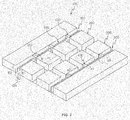
- FIG. 2 is a perspective view showing the main parts of a pneumatic tire according to the present invention.
- the present invention provides a pneumatic tire including a tread 100, sidewalls, and a bead portion, with blocks 200 and grooves 300 formed in the top surface of the tread 100, in which ground contact pressure reducing blocks 400 are mounted in the grooves 300 along the direction of travel adjoining the blocks 200, adjacent to forward directional trailing portions 210 of the blocks 200.
- ground contact pressure blocks 400 are mounted to the forward directional tailing portions 210 corresponding to the toe parts of the blocks 200, ground contact pressure can be instantaneously reduced by maintaining uniform distribution of ground contact pressure along the groove edges by increasing the ground contact area of the trailing portions of the tread blocks when coming into contact with the ground, thereby suppressing heel and toe wear.
- the increase in ground contact area leads to a decrease in ground contact pressure.
- FIG. 3 the relationship between ground contact pressure and friction coefficient conforms to Savkoor's friction law, which corresponds to a graph in which the friction coefficient increases with decreasing pressure, thus reducing the amount of slip.
- the direction-of-travel width s1 of the ground contact pressure reduction blocks 400 may be 5 to 20 % of the direction-of-travel length P1 of the blocks 200, the transverse width s2 may be 70 to 90 % of the width GW of the grooves 300 in which the ground contact pressure blocks 400 are mounted, and the height s3 of the ground contact pressure reducing blocks 400 may be equal to the depth d of the grooves 300 in which the ground contact pressure blocks 400 are mounted.
- the ground contact pressure reducing blocks 400 have the above dimensions so as not to impair the water drainage performance, etc. of the grooves 300. With these dimensions, however, the durability of the ground contact pressure reducing blocks 400 may be lowered. Accordingly, connecting ribs 500 may be mounted to connect the ground contact pressure reducing blocks 400.
- the height E1 of the connecting ribs 500 may be 10 to 50 % of the depth d of the grooves 300, and the width E2 of the connecting ribs 500 may be 10 to 30 % of the width GW of the grooves 300 to which the connecting ribs 500 are mounted.
- the present invention provides a pneumatic tire in which one end of the ground contact pressure reducing blocks 400 along the transverse direction adjoins the blocks 200, as shown in FIG. 4 .
- this exemplary embodiment may use a configuration in which one end of the ground contact pressure reducing blocks 400 along the transverse direction adjoins the blocks 200, as a way to substitute for the connecting ribs 500 of FIG. 2 .
- the durability of the ground contact pressure reducing blocks 400 may be greatly enhanced.
- the ground contact pressure reducing blocks 400 according to this exemplary embodiment may have the dimensions given in the previous exemplary embodiment.
Landscapes
- Engineering & Computer Science (AREA)
- Mechanical Engineering (AREA)
- Tires In General (AREA)
Abstract
Description
- The present invention relates to a pneumatic tire with improved wear resistance, and more particularly, to a pneumatic tire which improves uneven heel and toe wear on tread blocks of truck and bus radial (TBR) tires.
- In pneumatic car tires, especially, truck and bus radial (TBR) tires, heel and toe wear, a type of uneven wear on tread blocks, occurs frequently. Heel and toe wear happens when a part of a block that touches down first wears more slowly than a part that touches down later. The leading portion of the block, which wears at a slower rate, is called a heel, and the trailing portion, which wears at a faster rate, is called a toe.
- In order to reduce the aforementioned heel and toe wear, a structure for minimizing distortion of the heel part touching down first is employed. When driving a tire, force is exerted on the heel part in a direction opposite to which the car is traveling, and the rubber block is pushed back. Since rubber is incompressible, a lot of pressure is exerted on the toe part when the rubber block is pushed back, and this rapidly increase the slip velocity when the block slips away from the ground, thereby causing a lot of wear on the toe part. Accordingly, in order to minimize distortion of the heel part, the sides of grooves on the heel part are gently sloped, while the sides of the toe part are nearly vertical. However, it is difficult to reduce heel and toe wear by changing the angle of the sides of the grooves to reduce rubber distortion. This is due to an abrupt decrease in the force of friction on the toe part, which is caused by a rise in ground contact pressure on the toe part. Hence, there is a need for designs that increase the force of friction on the toe part.
- Hereinafter, conventional technologies for improving the above-described uneven heel and toe wear problem will be described. Identification numbers used in the conventional technologies are irrelevant to the present application.
- Korean Utility Model Registration No.
0125391 grooves 20 and the sipes 30 slope at the same angle on both sidewalls, so both sidewalls 22 and 24 of the grooves and both sidewalls 32 and 34 of the sipes do not wear at the same rate because of frequent braking and driving of the tire, but one sidewall, that is, the sidewall 24 and 34 positioned opposite to the direction of rotation of the tire, wears more quickly (heel and toe wear) than the sidewall 22 and 32 on the other side, thus shortening the overall lifespan of the tire. In view of this, the disclosure No.0125391 grooves 20, the sloping angle θb of the sidewall 24 aligned to the direction of rotation of the tire is obtuse and the sloping angle θa of the opposite sidewall 22 is acute. Likewise, of the two sidewalls 32 and 34 of the sipes 30, the sloping angle θd of the sidewall 34 aligned to the direction of rotation of the tire is obtuse and the sloping angle θc of the opposite sidewall 32 is acute. In the disclosure No.0125391 - Patent Registration No.
10-0782462 10-0782462 -
FIG. 1 is an example view of the conventional art explaining heel and toe wear. Referring toFIG. 1 , as described above, in the conventional art, the sides of grooves on the heel part are gently sloped, while the sides of the toe part are nearly vertical, in order to minimize distortion of the heel part. However, as previously mentioned, it is difficult to reduce heel and toe wear by changing the angle of the sides of the grooves to reduce rubber distortion. This is due to an abrupt decrease in the force of friction on the toe part, which is caused by a rise in ground contact pressure on the toe part. Hence, there is a need for designs that increase the force of friction on the toe part. -
- (Patent Document 1) Korean Patent Utility Model Registration No.
0125391 - (Patent Document 2) Korean Patent Registration No.
10-0782462 - A technical aspect of the present invention is directed to providing a pneumatic tire which can effectively improve heel and toe wear without deteriorating the stiffness of tread blocks.
- Technical aspects to be achieved by the present invention are not limited to the aforementioned technical aspect, and other technical aspects not mentioned above will be clearly understood by those skilled in the art from the following descriptions.
- An exemplary embodiment of the present invention provides a pneumatic tire including a tread, sidewalls, and a bead portion, with blocks and grooves formed in the top surface of the tread, in which ground contact pressure reducing blocks are mounted in the grooves along the direction of travel that adjoin the blocks, adjacent to forward directional trailing portions of the blocks.
- In the exemplary embodiment of the present invention, connecting ribs may be mounted to connect the ground contact pressure reducing blocks.
- In the exemplary embodiment of the present invention, the direction-of-travel width of the ground contact pressure reducing blocks may be 5 to 20 % of the direction-of-travel length of the blocks.
- In the exemplary embodiment of the present invention, the transverse width of the ground contact pressure reducing blocks may be 70 to 90 % of the width of the grooves in which the ground contact pressure blocks are mounted.
- In the exemplary embodiment of the present invention, the height of the ground contact pressure reducing blocks may be equal to the depth of the grooves in which the ground contact pressure blocks are mounted.
- In the exemplary embodiment of the present invention, the height of the connecting ribs may be 10 to 50 % of the depth d of the grooves.
- In the exemplary embodiment of the present invention, the width of the connecting ribs may be 10 to 30 % of the width of the grooves to which the connecting ribs are mounted.
- In the exemplary embodiment of the present invention, one end of the ground contact pressure reducing blocks along the transverse direction may adjoin the blocks.
- According to the exemplary embodiment of the present invention, ground contact pressure can be instantaneously reduced by maintaining uniform distribution of ground contact pressure along the groove edges by increasing the ground contact area of the trailing portions of the tread blocks, thereby suppressing heel and toe wear.
- The effects of the present invention are not limited to the above, but they should be construed as encompassing all the effects that can be inferred from a detailed description of the present invention or a construction of the invention set forth in the claims.
- The accompanying drawings, which are included to provide a further understanding of the invention and are incorporated in and constitute a part of this specification, illustrate embodiments of the invention and together with the description serve to explain the principles of the invention. In the drawings:
-
FIG. 1 is an example view of the conventional art explaining heel and toe wear; -
FIG. 2 is a perspective view showing the main parts of a pneumatic tire according to the present invention; -
FIG. 3 is a graph explaining the relationship between ground contact pressure and friction coefficient; and -
FIG. 4 is a perspective view showing the main parts of a pneumatic tire according to another exemplary embodiment of the present invention. - Hereinafter, the present invention will be described with reference to the accompanying drawings. The exemplary embodiments may, however, be embodied in many different forms and should not be construed as limited to the exemplary embodiments set forth herein. In the drawings, parts irrelevant to the descriptions are omitted for clarity, and like reference numerals refer to like parts throughout the specification.
- Throughout the specification, reference to a certain portion being "connected" to another portion not only encompasses cases of being "directly connected" but also encompasses cases of being "indirectly connected" by way of another member positioned in-between. When a certain part is described as "including" another component, this means that the part can further include other components and is not meant to exclude other components unless explicitly mentioned otherwise.
- The terms used in the specification are intended to describe particular embodiments only, and shall by no means be restrictive. Unless clearly used otherwise, expressions in a singular form include a meaning of a plural form. In the present description, an expression such as "comprising" or "including" is intended to designate a characteristic, a number, a step, an operation, an element, a part or combinations thereof, and shall not be construed to preclude any presence or possibility of one or more other characteristics, numbers, steps, operations, elements, parts or combinations thereof.
- Hereinafter, an exemplary embodiment of the present invention will be described in detail with reference to the accompanying drawings.
-
FIG. 2 is a perspective view showing the main parts of a pneumatic tire according to the present invention. - As shown in
FIG. 2 , the present invention provides a pneumatic tire including atread 100, sidewalls, and a bead portion, withblocks 200 andgrooves 300 formed in the top surface of thetread 100, in which ground contactpressure reducing blocks 400 are mounted in thegrooves 300 along the direction of travel adjoining theblocks 200, adjacent to forward directional trailingportions 210 of theblocks 200. - As the ground contact pressure blocks 400 are mounted to the forward directional tailing
portions 210 corresponding to the toe parts of theblocks 200, ground contact pressure can be instantaneously reduced by maintaining uniform distribution of ground contact pressure along the groove edges by increasing the ground contact area of the trailing portions of the tread blocks when coming into contact with the ground, thereby suppressing heel and toe wear. The increase in ground contact area leads to a decrease in ground contact pressure. Referring toFIG. 3 , the relationship between ground contact pressure and friction coefficient conforms to Savkoor's friction law, which corresponds to a graph in which the friction coefficient increases with decreasing pressure, thus reducing the amount of slip. The first graph ofFIG. 3 shows measurements on passenger car radial (PCR) tires, and the second graph shows measurements on truck and bus radial (TBR) tires. From the measurements in both graphs, it can be seen that the friction coefficient decreases with increasing pressure according to Savkoor's friction law. - To effectively distribute ground contact pressure when the toe parts of the
blocks 200 come into contact with the ground, the direction-of-travel width s1 of the ground contact pressure reduction blocks 400 may be 5 to 20 % of the direction-of-travel length P1 of theblocks 200, the transverse width s2 may be 70 to 90 % of the width GW of thegrooves 300 in which the ground contact pressure blocks 400 are mounted, and the height s3 of the ground contactpressure reducing blocks 400 may be equal to the depth d of thegrooves 300 in which the ground contact pressure blocks 400 are mounted. These numerical values are meaningful values that allow for uniform distribution of ground contact pressure on the toe parts, minimize the constraints on the water drainage performance, etc. of thegrooves 300, and make the ground contactpressure reducing blocks 400 distinguishable from neighboring, plain blocks. - The ground contact
pressure reducing blocks 400 have the above dimensions so as not to impair the water drainage performance, etc. of thegrooves 300. With these dimensions, however, the durability of the ground contactpressure reducing blocks 400 may be lowered. Accordingly, connectingribs 500 may be mounted to connect the ground contactpressure reducing blocks 400. The height E1 of the connectingribs 500 may be 10 to 50 % of the depth d of thegrooves 300, and the width E2 of the connectingribs 500 may be 10 to 30 % of the width GW of thegrooves 300 to which the connectingribs 500 are mounted. - These numerical values are meaningful values that increase the durability of the individual ground contact
pressure reducing blocks 400 and minimize the adverse effects on the water drainage performance, etc. of thegrooves 300. - In another exemplary embodiment, the present invention provides a pneumatic tire in which one end of the ground contact
pressure reducing blocks 400 along the transverse direction adjoins theblocks 200, as shown inFIG. 4 . As described above, with the above dimensions, the durability of the ground contactpressure reducing blocks 400 may be lowered. Therefore, this exemplary embodiment may use a configuration in which one end of the ground contactpressure reducing blocks 400 along the transverse direction adjoins theblocks 200, as a way to substitute for the connectingribs 500 ofFIG. 2 . With this configuration, the durability of the ground contactpressure reducing blocks 400 may be greatly enhanced. Preferably, the ground contactpressure reducing blocks 400 according to this exemplary embodiment may have the dimensions given in the previous exemplary embodiment. - The aforementioned description is provided for purposes of illustration and description. It will be appreciated by those skilled in the art that various modifications may be readily made without departing from the technical spirit or essential features of the disclosure. Thus, the exemplary embodiments should be understood to be illustrative in every aspect and not to be limiting. For example, each constituent element described in a singular form may be distributed and thereby implemented. Likewise, constituent elements described to be distributed may be implemented in a combined form.
- The scope of the disclosure is within the claims rather than the detailed description. Also, it is to be interpreted that the meanings and the scope of the claims and all the changes or modifications from the equivalents thereof are included in the scope of the disclosure.
Claims (8)
- A pneumatic tire comprising a tread, sidewalls, and a bead portion, with blocks and grooves formed in the top surface of the tread, in which ground contact pressure reducing blocks are mounted in the grooves along the direction of travel that adjoin the blocks, adjacent to forward directional trailing portions of the blocks.
- The pneumatic tire of claim 1, wherein connecting ribs are mounted to connect the ground contact pressure reducing blocks.
- The pneumatic tire of claim 1, wherein the direction-of-travel width of the ground contact pressure reducing blocks is 5 to 20 % of the direction-of-travel length of the blocks.
- The pneumatic tire of claim 1, wherein the transverse width of the ground contact pressure reducing blocks is 70 to 90 % of the width of the grooves in which the ground contact pressure blocks are mounted.
- The pneumatic tire of claim 1, wherein the height of the ground contact pressure reducing blocks is equal to the depth of the grooves in which the ground contact pressure blocks are mounted.
- The pneumatic tire of claim 2, wherein the height of the connecting ribs is 10 to 50 % of the depth d of the grooves.
- The pneumatic tire of claim 2, wherein the width of the connecting ribs may be 10 to 30 % of the width of the grooves to which the connecting ribs are mounted.
- The pneumatic tire of any one of claims 1, 3, and 5, wherein one end of the ground contact pressure reducing blocks along the transverse direction adjoins the blocks.
Applications Claiming Priority (1)
| Application Number | Priority Date | Filing Date | Title |
|---|---|---|---|
| KR1020160134640A KR101859839B1 (en) | 2016-10-17 | 2016-10-17 | A pneumatic tire |
Publications (2)
| Publication Number | Publication Date |
|---|---|
| EP3308979A1 true EP3308979A1 (en) | 2018-04-18 |
| EP3308979B1 EP3308979B1 (en) | 2022-08-24 |
Family
ID=60119943
Family Applications (1)
| Application Number | Title | Priority Date | Filing Date |
|---|---|---|---|
| EP17196805.0A Active EP3308979B1 (en) | 2016-10-17 | 2017-10-17 | Pneumatic tire |
Country Status (5)
| Country | Link |
|---|---|
| US (1) | US20180104991A1 (en) |
| EP (1) | EP3308979B1 (en) |
| JP (1) | JP6550436B2 (en) |
| KR (1) | KR101859839B1 (en) |
| CN (1) | CN107953727B (en) |
Families Citing this family (1)
| Publication number | Priority date | Publication date | Assignee | Title |
|---|---|---|---|---|
| WO2025215519A1 (en) * | 2024-04-09 | 2025-10-16 | Pirelli Tyre S.P.A. | Off-road motorcycle tyre |
Citations (8)
| Publication number | Priority date | Publication date | Assignee | Title |
|---|---|---|---|---|
| JPS63306904A (en) * | 1987-06-09 | 1988-12-14 | Bridgestone Corp | Pneumatic bias tire for emergency use |
| EP0455925A1 (en) * | 1990-05-10 | 1991-11-13 | The Goodyear Tire & Rubber Company | All season type tire tread |
| KR0125391Y1 (en) | 1995-11-08 | 1998-10-01 | 홍건희 | Tires with improved wear resistance |
| US5891276A (en) * | 1996-10-28 | 1999-04-06 | The Yokohama Rubber Co., Ltd. | Pneumatic tire for heavy duty including narrow block |
| EP0936088A2 (en) * | 1998-02-12 | 1999-08-18 | Sumitomo Rubber Industries Limited | Pneumatic tyre |
| EP1619050A1 (en) * | 2004-07-21 | 2006-01-25 | The Goodyear Tire & Rubber Company | Pneumatic tire |
| EP1676693A1 (en) * | 2004-12-28 | 2006-07-05 | The Goodyear Tire & Rubber Company | Pneumatic tire with improved tie bar |
| KR100782462B1 (en) | 2004-07-09 | 2007-12-05 | 한국타이어 주식회사 | Tread block cuff structure with improved block wear rigidity |
Family Cites Families (9)
| Publication number | Priority date | Publication date | Assignee | Title |
|---|---|---|---|---|
| JP3026746B2 (en) * | 1995-11-02 | 2000-03-27 | 住友ゴム工業株式会社 | Winter tires |
| JPH11301216A (en) * | 1998-04-24 | 1999-11-02 | Bridgestone Corp | Pneumatic radial tire |
| JP2002234313A (en) * | 2001-02-08 | 2002-08-20 | Bridgestone Corp | Pneumatic tire |
| JP2003146021A (en) * | 2001-11-12 | 2003-05-21 | Bridgestone Corp | Pneumatic tire |
| JP4938387B2 (en) * | 2006-08-31 | 2012-05-23 | 東洋ゴム工業株式会社 | Pneumatic tire |
| JP2013248927A (en) * | 2012-05-30 | 2013-12-12 | Bridgestone Corp | Pneumatic tire |
| JP5973942B2 (en) * | 2013-03-15 | 2016-08-23 | 住友ゴム工業株式会社 | Pneumatic tire |
| US9636952B2 (en) * | 2014-01-08 | 2017-05-02 | Sumitomo Rubber Industries, Ltd. | Heavy duty pneumatic tire |
| BR112017006738A2 (en) * | 2014-10-06 | 2017-12-19 | Bridgestone Americas Tire Operations Llc | tire traction element |
-
2016
- 2016-10-17 KR KR1020160134640A patent/KR101859839B1/en not_active Expired - Fee Related
-
2017
- 2017-10-17 US US15/786,496 patent/US20180104991A1/en not_active Abandoned
- 2017-10-17 JP JP2017200947A patent/JP6550436B2/en active Active
- 2017-10-17 CN CN201710965661.1A patent/CN107953727B/en not_active Expired - Fee Related
- 2017-10-17 EP EP17196805.0A patent/EP3308979B1/en active Active
Patent Citations (8)
| Publication number | Priority date | Publication date | Assignee | Title |
|---|---|---|---|---|
| JPS63306904A (en) * | 1987-06-09 | 1988-12-14 | Bridgestone Corp | Pneumatic bias tire for emergency use |
| EP0455925A1 (en) * | 1990-05-10 | 1991-11-13 | The Goodyear Tire & Rubber Company | All season type tire tread |
| KR0125391Y1 (en) | 1995-11-08 | 1998-10-01 | 홍건희 | Tires with improved wear resistance |
| US5891276A (en) * | 1996-10-28 | 1999-04-06 | The Yokohama Rubber Co., Ltd. | Pneumatic tire for heavy duty including narrow block |
| EP0936088A2 (en) * | 1998-02-12 | 1999-08-18 | Sumitomo Rubber Industries Limited | Pneumatic tyre |
| KR100782462B1 (en) | 2004-07-09 | 2007-12-05 | 한국타이어 주식회사 | Tread block cuff structure with improved block wear rigidity |
| EP1619050A1 (en) * | 2004-07-21 | 2006-01-25 | The Goodyear Tire & Rubber Company | Pneumatic tire |
| EP1676693A1 (en) * | 2004-12-28 | 2006-07-05 | The Goodyear Tire & Rubber Company | Pneumatic tire with improved tie bar |
Also Published As
| Publication number | Publication date |
|---|---|
| US20180104991A1 (en) | 2018-04-19 |
| JP2018065560A (en) | 2018-04-26 |
| KR20180042051A (en) | 2018-04-25 |
| CN107953727A (en) | 2018-04-24 |
| KR101859839B1 (en) | 2018-05-18 |
| EP3308979B1 (en) | 2022-08-24 |
| JP6550436B2 (en) | 2019-07-24 |
| CN107953727B (en) | 2020-05-19 |
Similar Documents
| Publication | Publication Date | Title |
|---|---|---|
| KR101592038B1 (en) | Heavy duty tire | |
| JP4899650B2 (en) | Pneumatic tire | |
| CN102985267B (en) | tread protection device | |
| US9469159B2 (en) | Pneumatic tire | |
| CN106394140B (en) | Pneumatic tires for heavy duty | |
| CN106852135A (en) | The tire tread of the variable thickness tread groove in region including reducing with multiple thickness | |
| CN101186168A (en) | pneumatic tire | |
| CN102795059A (en) | Commercial truck tire | |
| CN110406325A (en) | Prevents irregularly worn tires | |
| JP2011240750A (en) | Pneumatic tire | |
| CN109562654B (en) | Pneumatic tire for vehicle | |
| CN108349317B (en) | Agricultural tire | |
| CN108367626B (en) | Tire treads for heavy civil engineering vehicles | |
| JP6579895B2 (en) | Pneumatic tire | |
| JP6527758B2 (en) | Pneumatic tire | |
| JP5403985B2 (en) | Pneumatic tire | |
| EP1676728B1 (en) | Siped tire tread | |
| EP3308979B1 (en) | Pneumatic tire | |
| AU2015293161B2 (en) | Pneumatic tire for heavy loads | |
| CN104837651B (en) | Method for increasing performance of tyre for heavy load vehicle wheels and tyre for heavy load vehicle wheels | |
| KR100902393B1 (en) | Heavy-duty pneumatic radial tires with directional lug pattern | |
| JP6748413B2 (en) | Pneumatic tire | |
| KR102740641B1 (en) | A pneumatic tire | |
| RU2614401C2 (en) | Thick protector for construction machinery | |
| JP6387144B1 (en) | Pneumatic tire |
Legal Events
| Date | Code | Title | Description |
|---|---|---|---|
| PUAI | Public reference made under article 153(3) epc to a published international application that has entered the european phase |
Free format text: ORIGINAL CODE: 0009012 |
|
| STAA | Information on the status of an ep patent application or granted ep patent |
Free format text: STATUS: REQUEST FOR EXAMINATION WAS MADE |
|
| 17P | Request for examination filed |
Effective date: 20171017 |
|
| AK | Designated contracting states |
Kind code of ref document: A1 Designated state(s): AL AT BE BG CH CY CZ DE DK EE ES FI FR GB GR HR HU IE IS IT LI LT LU LV MC MK MT NL NO PL PT RO RS SE SI SK SM TR |
|
| AX | Request for extension of the european patent |
Extension state: BA ME |
|
| RBV | Designated contracting states (corrected) |
Designated state(s): AL AT BE BG CH CY CZ DE DK EE ES FI FR GB GR HR HU IE IS IT LI LT LU LV MC MK MT NL NO PL PT RO RS SE SI SK SM TR |
|
| R17P | Request for examination filed (corrected) |
Effective date: 20171017 |
|
| STAA | Information on the status of an ep patent application or granted ep patent |
Free format text: STATUS: EXAMINATION IS IN PROGRESS |
|
| 17Q | First examination report despatched |
Effective date: 20210323 |
|
| GRAP | Despatch of communication of intention to grant a patent |
Free format text: ORIGINAL CODE: EPIDOSNIGR1 |
|
| STAA | Information on the status of an ep patent application or granted ep patent |
Free format text: STATUS: GRANT OF PATENT IS INTENDED |
|
| INTG | Intention to grant announced |
Effective date: 20220309 |
|
| GRAS | Grant fee paid |
Free format text: ORIGINAL CODE: EPIDOSNIGR3 |
|
| GRAA | (expected) grant |
Free format text: ORIGINAL CODE: 0009210 |
|
| STAA | Information on the status of an ep patent application or granted ep patent |
Free format text: STATUS: THE PATENT HAS BEEN GRANTED |
|
| AK | Designated contracting states |
Kind code of ref document: B1 Designated state(s): AL AT BE BG CH CY CZ DE DK EE ES FI FR GB GR HR HU IE IS IT LI LT LU LV MC MK MT NL NO PL PT RO RS SE SI SK SM TR |
|
| REG | Reference to a national code |
Ref country code: CH Ref legal event code: EP |
|
| REG | Reference to a national code |
Ref country code: IE Ref legal event code: FG4D |
|
| REG | Reference to a national code |
Ref country code: AT Ref legal event code: REF Ref document number: 1513401 Country of ref document: AT Kind code of ref document: T Effective date: 20220915 Ref country code: DE Ref legal event code: R096 Ref document number: 602017060932 Country of ref document: DE |
|
| REG | Reference to a national code |
Ref country code: LT Ref legal event code: MG9D |
|
| REG | Reference to a national code |
Ref country code: NL Ref legal event code: MP Effective date: 20220824 |
|
| PG25 | Lapsed in a contracting state [announced via postgrant information from national office to epo] |
Ref country code: SE Free format text: LAPSE BECAUSE OF FAILURE TO SUBMIT A TRANSLATION OF THE DESCRIPTION OR TO PAY THE FEE WITHIN THE PRESCRIBED TIME-LIMIT Effective date: 20220824 Ref country code: RS Free format text: LAPSE BECAUSE OF FAILURE TO SUBMIT A TRANSLATION OF THE DESCRIPTION OR TO PAY THE FEE WITHIN THE PRESCRIBED TIME-LIMIT Effective date: 20220824 Ref country code: PT Free format text: LAPSE BECAUSE OF FAILURE TO SUBMIT A TRANSLATION OF THE DESCRIPTION OR TO PAY THE FEE WITHIN THE PRESCRIBED TIME-LIMIT Effective date: 20221226 Ref country code: NO Free format text: LAPSE BECAUSE OF FAILURE TO SUBMIT A TRANSLATION OF THE DESCRIPTION OR TO PAY THE FEE WITHIN THE PRESCRIBED TIME-LIMIT Effective date: 20221124 Ref country code: NL Free format text: LAPSE BECAUSE OF FAILURE TO SUBMIT A TRANSLATION OF THE DESCRIPTION OR TO PAY THE FEE WITHIN THE PRESCRIBED TIME-LIMIT Effective date: 20220824 Ref country code: LV Free format text: LAPSE BECAUSE OF FAILURE TO SUBMIT A TRANSLATION OF THE DESCRIPTION OR TO PAY THE FEE WITHIN THE PRESCRIBED TIME-LIMIT Effective date: 20220824 Ref country code: LT Free format text: LAPSE BECAUSE OF FAILURE TO SUBMIT A TRANSLATION OF THE DESCRIPTION OR TO PAY THE FEE WITHIN THE PRESCRIBED TIME-LIMIT Effective date: 20220824 Ref country code: FI Free format text: LAPSE BECAUSE OF FAILURE TO SUBMIT A TRANSLATION OF THE DESCRIPTION OR TO PAY THE FEE WITHIN THE PRESCRIBED TIME-LIMIT Effective date: 20220824 |
|
| REG | Reference to a national code |
Ref country code: AT Ref legal event code: MK05 Ref document number: 1513401 Country of ref document: AT Kind code of ref document: T Effective date: 20220824 |
|
| PG25 | Lapsed in a contracting state [announced via postgrant information from national office to epo] |
Ref country code: PL Free format text: LAPSE BECAUSE OF FAILURE TO SUBMIT A TRANSLATION OF THE DESCRIPTION OR TO PAY THE FEE WITHIN THE PRESCRIBED TIME-LIMIT Effective date: 20220824 Ref country code: IS Free format text: LAPSE BECAUSE OF FAILURE TO SUBMIT A TRANSLATION OF THE DESCRIPTION OR TO PAY THE FEE WITHIN THE PRESCRIBED TIME-LIMIT Effective date: 20221224 Ref country code: HR Free format text: LAPSE BECAUSE OF FAILURE TO SUBMIT A TRANSLATION OF THE DESCRIPTION OR TO PAY THE FEE WITHIN THE PRESCRIBED TIME-LIMIT Effective date: 20220824 Ref country code: GR Free format text: LAPSE BECAUSE OF FAILURE TO SUBMIT A TRANSLATION OF THE DESCRIPTION OR TO PAY THE FEE WITHIN THE PRESCRIBED TIME-LIMIT Effective date: 20221125 |
|
| PG25 | Lapsed in a contracting state [announced via postgrant information from national office to epo] |
Ref country code: SM Free format text: LAPSE BECAUSE OF FAILURE TO SUBMIT A TRANSLATION OF THE DESCRIPTION OR TO PAY THE FEE WITHIN THE PRESCRIBED TIME-LIMIT Effective date: 20220824 Ref country code: RO Free format text: LAPSE BECAUSE OF FAILURE TO SUBMIT A TRANSLATION OF THE DESCRIPTION OR TO PAY THE FEE WITHIN THE PRESCRIBED TIME-LIMIT Effective date: 20220824 Ref country code: ES Free format text: LAPSE BECAUSE OF FAILURE TO SUBMIT A TRANSLATION OF THE DESCRIPTION OR TO PAY THE FEE WITHIN THE PRESCRIBED TIME-LIMIT Effective date: 20220824 Ref country code: DK Free format text: LAPSE BECAUSE OF FAILURE TO SUBMIT A TRANSLATION OF THE DESCRIPTION OR TO PAY THE FEE WITHIN THE PRESCRIBED TIME-LIMIT Effective date: 20220824 Ref country code: CZ Free format text: LAPSE BECAUSE OF FAILURE TO SUBMIT A TRANSLATION OF THE DESCRIPTION OR TO PAY THE FEE WITHIN THE PRESCRIBED TIME-LIMIT Effective date: 20220824 Ref country code: AT Free format text: LAPSE BECAUSE OF FAILURE TO SUBMIT A TRANSLATION OF THE DESCRIPTION OR TO PAY THE FEE WITHIN THE PRESCRIBED TIME-LIMIT Effective date: 20220824 |
|
| REG | Reference to a national code |
Ref country code: DE Ref legal event code: R097 Ref document number: 602017060932 Country of ref document: DE |
|
| PG25 | Lapsed in a contracting state [announced via postgrant information from national office to epo] |
Ref country code: SK Free format text: LAPSE BECAUSE OF FAILURE TO SUBMIT A TRANSLATION OF THE DESCRIPTION OR TO PAY THE FEE WITHIN THE PRESCRIBED TIME-LIMIT Effective date: 20220824 Ref country code: MC Free format text: LAPSE BECAUSE OF FAILURE TO SUBMIT A TRANSLATION OF THE DESCRIPTION OR TO PAY THE FEE WITHIN THE PRESCRIBED TIME-LIMIT Effective date: 20220824 Ref country code: EE Free format text: LAPSE BECAUSE OF FAILURE TO SUBMIT A TRANSLATION OF THE DESCRIPTION OR TO PAY THE FEE WITHIN THE PRESCRIBED TIME-LIMIT Effective date: 20220824 |
|
| REG | Reference to a national code |
Ref country code: CH Ref legal event code: PL |
|
| REG | Reference to a national code |
Ref country code: BE Ref legal event code: MM Effective date: 20221031 |
|
| PG25 | Lapsed in a contracting state [announced via postgrant information from national office to epo] |
Ref country code: LU Free format text: LAPSE BECAUSE OF NON-PAYMENT OF DUE FEES Effective date: 20221017 Ref country code: AL Free format text: LAPSE BECAUSE OF FAILURE TO SUBMIT A TRANSLATION OF THE DESCRIPTION OR TO PAY THE FEE WITHIN THE PRESCRIBED TIME-LIMIT Effective date: 20220824 |
|
| PLBE | No opposition filed within time limit |
Free format text: ORIGINAL CODE: 0009261 |
|
| STAA | Information on the status of an ep patent application or granted ep patent |
Free format text: STATUS: NO OPPOSITION FILED WITHIN TIME LIMIT |
|
| GBPC | Gb: european patent ceased through non-payment of renewal fee |
Effective date: 20221124 |
|
| PG25 | Lapsed in a contracting state [announced via postgrant information from national office to epo] |
Ref country code: LI Free format text: LAPSE BECAUSE OF NON-PAYMENT OF DUE FEES Effective date: 20221031 Ref country code: CH Free format text: LAPSE BECAUSE OF NON-PAYMENT OF DUE FEES Effective date: 20221031 |
|
| 26N | No opposition filed |
Effective date: 20230525 |
|
| PG25 | Lapsed in a contracting state [announced via postgrant information from national office to epo] |
Ref country code: SI Free format text: LAPSE BECAUSE OF FAILURE TO SUBMIT A TRANSLATION OF THE DESCRIPTION OR TO PAY THE FEE WITHIN THE PRESCRIBED TIME-LIMIT Effective date: 20220824 |
|
| PG25 | Lapsed in a contracting state [announced via postgrant information from national office to epo] |
Ref country code: BE Free format text: LAPSE BECAUSE OF NON-PAYMENT OF DUE FEES Effective date: 20221031 |
|
| PG25 | Lapsed in a contracting state [announced via postgrant information from national office to epo] |
Ref country code: IE Free format text: LAPSE BECAUSE OF NON-PAYMENT OF DUE FEES Effective date: 20221017 Ref country code: GB Free format text: LAPSE BECAUSE OF NON-PAYMENT OF DUE FEES Effective date: 20221124 |
|
| P01 | Opt-out of the competence of the unified patent court (upc) registered |
Effective date: 20230926 |
|
| PG25 | Lapsed in a contracting state [announced via postgrant information from national office to epo] |
Ref country code: HU Free format text: LAPSE BECAUSE OF FAILURE TO SUBMIT A TRANSLATION OF THE DESCRIPTION OR TO PAY THE FEE WITHIN THE PRESCRIBED TIME-LIMIT; INVALID AB INITIO Effective date: 20171017 |
|
| PG25 | Lapsed in a contracting state [announced via postgrant information from national office to epo] |
Ref country code: CY Free format text: LAPSE BECAUSE OF FAILURE TO SUBMIT A TRANSLATION OF THE DESCRIPTION OR TO PAY THE FEE WITHIN THE PRESCRIBED TIME-LIMIT Effective date: 20220824 |
|
| PG25 | Lapsed in a contracting state [announced via postgrant information from national office to epo] |
Ref country code: MK Free format text: LAPSE BECAUSE OF FAILURE TO SUBMIT A TRANSLATION OF THE DESCRIPTION OR TO PAY THE FEE WITHIN THE PRESCRIBED TIME-LIMIT Effective date: 20220824 Ref country code: IT Free format text: LAPSE BECAUSE OF FAILURE TO SUBMIT A TRANSLATION OF THE DESCRIPTION OR TO PAY THE FEE WITHIN THE PRESCRIBED TIME-LIMIT Effective date: 20220824 |
|
| PG25 | Lapsed in a contracting state [announced via postgrant information from national office to epo] |
Ref country code: BG Free format text: LAPSE BECAUSE OF FAILURE TO SUBMIT A TRANSLATION OF THE DESCRIPTION OR TO PAY THE FEE WITHIN THE PRESCRIBED TIME-LIMIT Effective date: 20220824 |
|
| PG25 | Lapsed in a contracting state [announced via postgrant information from national office to epo] |
Ref country code: MT Free format text: LAPSE BECAUSE OF FAILURE TO SUBMIT A TRANSLATION OF THE DESCRIPTION OR TO PAY THE FEE WITHIN THE PRESCRIBED TIME-LIMIT Effective date: 20220824 |
|
| PGFP | Annual fee paid to national office [announced via postgrant information from national office to epo] |
Ref country code: FR Payment date: 20250925 Year of fee payment: 9 |
|
| PG25 | Lapsed in a contracting state [announced via postgrant information from national office to epo] |
Ref country code: TR Free format text: LAPSE BECAUSE OF FAILURE TO SUBMIT A TRANSLATION OF THE DESCRIPTION OR TO PAY THE FEE WITHIN THE PRESCRIBED TIME-LIMIT Effective date: 20220824 |
|
| PGFP | Annual fee paid to national office [announced via postgrant information from national office to epo] |
Ref country code: DE Payment date: 20250922 Year of fee payment: 9 |