EP3308960B1 - Réservoir d'huile de turbomachine - Google Patents
Réservoir d'huile de turbomachine Download PDFInfo
- Publication number
- EP3308960B1 EP3308960B1 EP17194670.0A EP17194670A EP3308960B1 EP 3308960 B1 EP3308960 B1 EP 3308960B1 EP 17194670 A EP17194670 A EP 17194670A EP 3308960 B1 EP3308960 B1 EP 3308960B1
- Authority
- EP
- European Patent Office
- Prior art keywords
- envelope
- tank
- fixing portion
- fixing
- casing
- Prior art date
- Legal status (The legal status is an assumption and is not a legal conclusion. Google has not performed a legal analysis and makes no representation as to the accuracy of the status listed.)
- Active
Links
Images



Classifications
-
- F—MECHANICAL ENGINEERING; LIGHTING; HEATING; WEAPONS; BLASTING
- F16—ENGINEERING ELEMENTS AND UNITS; GENERAL MEASURES FOR PRODUCING AND MAINTAINING EFFECTIVE FUNCTIONING OF MACHINES OR INSTALLATIONS; THERMAL INSULATION IN GENERAL
- F16N—LUBRICATING
- F16N19/00—Lubricant containers for use in lubricators or lubrication systems
-
- B—PERFORMING OPERATIONS; TRANSPORTING
- B22—CASTING; POWDER METALLURGY
- B22F—WORKING METALLIC POWDER; MANUFACTURE OF ARTICLES FROM METALLIC POWDER; MAKING METALLIC POWDER; APPARATUS OR DEVICES SPECIALLY ADAPTED FOR METALLIC POWDER
- B22F10/00—Additive manufacturing of workpieces or articles from metallic powder
-
- B—PERFORMING OPERATIONS; TRANSPORTING
- B22—CASTING; POWDER METALLURGY
- B22F—WORKING METALLIC POWDER; MANUFACTURE OF ARTICLES FROM METALLIC POWDER; MAKING METALLIC POWDER; APPARATUS OR DEVICES SPECIALLY ADAPTED FOR METALLIC POWDER
- B22F10/00—Additive manufacturing of workpieces or articles from metallic powder
- B22F10/20—Direct sintering or melting
- B22F10/28—Powder bed fusion, e.g. selective laser melting [SLM] or electron beam melting [EBM]
-
- B—PERFORMING OPERATIONS; TRANSPORTING
- B22—CASTING; POWDER METALLURGY
- B22F—WORKING METALLIC POWDER; MANUFACTURE OF ARTICLES FROM METALLIC POWDER; MAKING METALLIC POWDER; APPARATUS OR DEVICES SPECIALLY ADAPTED FOR METALLIC POWDER
- B22F5/00—Manufacture of workpieces or articles from metallic powder characterised by the special shape of the product
- B22F5/009—Manufacture of workpieces or articles from metallic powder characterised by the special shape of the product of turbine components other than turbine blades
-
- B—PERFORMING OPERATIONS; TRANSPORTING
- B33—ADDITIVE MANUFACTURING TECHNOLOGY
- B33Y—ADDITIVE MANUFACTURING, i.e. MANUFACTURING OF THREE-DIMENSIONAL [3D] OBJECTS BY ADDITIVE DEPOSITION, ADDITIVE AGGLOMERATION OR ADDITIVE LAYERING, e.g. BY 3D PRINTING, STEREOLITHOGRAPHY OR SELECTIVE LASER SINTERING
- B33Y80/00—Products made by additive manufacturing
-
- F—MECHANICAL ENGINEERING; LIGHTING; HEATING; WEAPONS; BLASTING
- F01—MACHINES OR ENGINES IN GENERAL; ENGINE PLANTS IN GENERAL; STEAM ENGINES
- F01D—NON-POSITIVE DISPLACEMENT MACHINES OR ENGINES, e.g. STEAM TURBINES
- F01D25/00—Component parts, details, or accessories, not provided for in, or of interest apart from, other groups
- F01D25/18—Lubricating arrangements
-
- F—MECHANICAL ENGINEERING; LIGHTING; HEATING; WEAPONS; BLASTING
- F01—MACHINES OR ENGINES IN GENERAL; ENGINE PLANTS IN GENERAL; STEAM ENGINES
- F01D—NON-POSITIVE DISPLACEMENT MACHINES OR ENGINES, e.g. STEAM TURBINES
- F01D25/00—Component parts, details, or accessories, not provided for in, or of interest apart from, other groups
- F01D25/28—Supporting or mounting arrangements, e.g. for turbine casing
-
- F—MECHANICAL ENGINEERING; LIGHTING; HEATING; WEAPONS; BLASTING
- F02—COMBUSTION ENGINES; HOT-GAS OR COMBUSTION-PRODUCT ENGINE PLANTS
- F02C—GAS-TURBINE PLANTS; AIR INTAKES FOR JET-PROPULSION PLANTS; CONTROLLING FUEL SUPPLY IN AIR-BREATHING JET-PROPULSION PLANTS
- F02C7/00—Features, components parts, details or accessories, not provided for in, or of interest apart form groups F02C1/00 - F02C6/00; Air intakes for jet-propulsion plants
- F02C7/06—Arrangements of bearings; Lubricating
-
- B—PERFORMING OPERATIONS; TRANSPORTING
- B22—CASTING; POWDER METALLURGY
- B22F—WORKING METALLIC POWDER; MANUFACTURE OF ARTICLES FROM METALLIC POWDER; MAKING METALLIC POWDER; APPARATUS OR DEVICES SPECIALLY ADAPTED FOR METALLIC POWDER
- B22F10/00—Additive manufacturing of workpieces or articles from metallic powder
- B22F10/30—Process control
- B22F10/36—Process control of energy beam parameters
- B22F10/362—Process control of energy beam parameters for preheating
-
- B—PERFORMING OPERATIONS; TRANSPORTING
- B22—CASTING; POWDER METALLURGY
- B22F—WORKING METALLIC POWDER; MANUFACTURE OF ARTICLES FROM METALLIC POWDER; MAKING METALLIC POWDER; APPARATUS OR DEVICES SPECIALLY ADAPTED FOR METALLIC POWDER
- B22F10/00—Additive manufacturing of workpieces or articles from metallic powder
- B22F10/60—Treatment of workpieces or articles after build-up
- B22F10/66—Treatment of workpieces or articles after build-up by mechanical means
-
- B—PERFORMING OPERATIONS; TRANSPORTING
- B22—CASTING; POWDER METALLURGY
- B22F—WORKING METALLIC POWDER; MANUFACTURE OF ARTICLES FROM METALLIC POWDER; MAKING METALLIC POWDER; APPARATUS OR DEVICES SPECIALLY ADAPTED FOR METALLIC POWDER
- B22F2301/00—Metallic composition of the powder or its coating
- B22F2301/15—Nickel or cobalt
-
- B—PERFORMING OPERATIONS; TRANSPORTING
- B22—CASTING; POWDER METALLURGY
- B22F—WORKING METALLIC POWDER; MANUFACTURE OF ARTICLES FROM METALLIC POWDER; MAKING METALLIC POWDER; APPARATUS OR DEVICES SPECIALLY ADAPTED FOR METALLIC POWDER
- B22F2301/00—Metallic composition of the powder or its coating
- B22F2301/20—Refractory metals
- B22F2301/205—Titanium, zirconium or hafnium
-
- F—MECHANICAL ENGINEERING; LIGHTING; HEATING; WEAPONS; BLASTING
- F01—MACHINES OR ENGINES IN GENERAL; ENGINE PLANTS IN GENERAL; STEAM ENGINES
- F01M—LUBRICATING OF MACHINES OR ENGINES IN GENERAL; LUBRICATING INTERNAL COMBUSTION ENGINES; CRANKCASE VENTILATING
- F01M11/00—Component parts, details or accessories, not provided for in, or of interest apart from, groups F01M1/00 - F01M9/00
- F01M11/0004—Oilsumps
- F01M2011/0091—Oilsumps characterised by used materials
-
- F—MECHANICAL ENGINEERING; LIGHTING; HEATING; WEAPONS; BLASTING
- F16—ENGINEERING ELEMENTS AND UNITS; GENERAL MEASURES FOR PRODUCING AND MAINTAINING EFFECTIVE FUNCTIONING OF MACHINES OR INSTALLATIONS; THERMAL INSULATION IN GENERAL
- F16N—LUBRICATING
- F16N2210/00—Applications
- F16N2210/08—Aircraft
-
- Y—GENERAL TAGGING OF NEW TECHNOLOGICAL DEVELOPMENTS; GENERAL TAGGING OF CROSS-SECTIONAL TECHNOLOGIES SPANNING OVER SEVERAL SECTIONS OF THE IPC; TECHNICAL SUBJECTS COVERED BY FORMER USPC CROSS-REFERENCE ART COLLECTIONS [XRACs] AND DIGESTS
- Y02—TECHNOLOGIES OR APPLICATIONS FOR MITIGATION OR ADAPTATION AGAINST CLIMATE CHANGE
- Y02P—CLIMATE CHANGE MITIGATION TECHNOLOGIES IN THE PRODUCTION OR PROCESSING OF GOODS
- Y02P10/00—Technologies related to metal processing
- Y02P10/25—Process efficiency
Definitions
- the invention relates to the manufacture of a turbomachine tank. More specifically, the invention deals with the manufacture of a metal reservoir for turbojet oil.
- the invention also relates to an axial turbomachine, in particular an aircraft turbojet or an aircraft turboprop.
- the invention also proposes a method for manufacturing a reservoir
- the lubrication of a turbojet engine is based on a continuous circulation of oil.
- This oil uses a dedicated network which is connected to a tank specific to the turbojet engine. This reservoir forms both the starting point and the arrival point of the network. In addition, it offers a buffer volume which compensates for an accumulation of oil in certain areas, just like oil consumption. Of course, the tank must remain fixed to the turbojet despite its filling level and the vibrations.
- the documents FR 2 485 630 A1 and US 3,316,692A disclose a turbojet engine with a casing supporting an oil reservoir with an anti-vibration system.
- the tank envelope is crossed by an axis linked to thickenings of the envelope.
- the ends of the shaft which come out of the casing form fastening members in flexible engagement with the support casing of the turbojet engine.
- the shaft forms a hollow body with machined collars which are in contact with the thickenings of the casing.
- a series of parallel internal partitions is linked to the axis so as to reinforce the envelope.
- Such a tank actually tends to show a certain resistance to vibrations, but which remains perfectible.
- the object of the invention is to solve at least one of the problems posed by the prior art. More specifically, the invention aims to improve the vibration resistance of a turbojet oil tank. The invention also aims to provide a solution that is simple, light, economical, reliable, compact, easy to inspect.
- the subject of the invention is a turbojet engine tank for oil, the tank comprising a main chamber, a casing delimiting the main chamber, and a fixing portion; the casing comprising a part of the casing with respect to which the fixing portion projects, in particular towards the outside; remarkable in that the envelope part and the fixing portion are produced by additive manufacturing in layers so as to be made in one piece.
- the technical characteristic specifying that the envelope part and the fixing portion are made by additive manufacturing in layers so as to be made in one piece, is not an essential characteristic of the invention. It can be replaced by one of the following characteristics.
- the tank may include one or more of the following characteristics, taken individually or according to all possible technical combinations:
- the fixing portion comprises a first fixing flange projecting with respect to the partition, and possibly a second fixing flange projecting with respect to the envelope, the envelope optionally comprising a base forming an extra thickness on the envelope part at least one or each flange.
- the casing has a first zone of less thickness between the two fixing flanges and/or opposite the two fixing flanges.
- At least one or each of the two mounting flanges includes a curved free edge.
- At least one or each of the two fixing flanges has a triangle shape, possibly asymmetrical.
- the tank comprises an internal stiffener extending the fixing portion, in particular a fixing flange, towards the chamber; said internal stiffener, the casing part and the fixing portion being produced by additive manufacturing so as to be made in one piece.
- the casing comprises one end with a second zone of less thickness, said end optionally being a lower end of the tank.
- the casing comprises a reinforcement belt or a portion of a reinforcement belt, the reinforcement belt or the portion of a reinforcement belt, the part of the envelope and the attachment portion are produced by additive manufacturing so as to be made in one piece .
- the tank comprises at least one piece of equipment such as a vent, and/or a deaerator, and/or a probe support, and/or a strainer; each piece of equipment, the casing part and the fixing portion being produced by additive manufacturing so as to be made in one piece.
- equipment such as a vent, and/or a deaerator, and/or a probe support, and/or a strainer
- the casing part is a first casing part, the casing further comprising a second casing part produced by additive manufacturing in layers and welded to the first casing part by a weld.
- the main chamber has a main elongation, the first weld being generally perpendicular to said main elongation.
- the first casing part forms a bottom of the reservoir and/or the second casing part forms a reservoir lid.
- the casing comprises a face where the fixing portion is arranged, and a thinning opposite said face.
- the main chamber has the general shape of a cylinder, possibly curved.
- At least one or each of the two flanges is joined to the reinforcement belt or to the reinforcement belt portion.
- At least or each of the two flanges is a plate, in particular of the same material as the casing.
- the stiffener comprises a mesh occupying the entire main chamber.
- the material of the casing part and of the attachment portion has a stack of layers of material along a stacking direction which is transverse to the thickness of said casing part.
- the envelope part is in one piece.
- the stiffener passes through the internal chamber, possibly horizontally.
- the casing comprises two extra thickness zones which are each at the base of a fixing flange, and a third zone of less thickness separating said two extra thickness zones.
- the casing is metallic, for example steel.
- the minimum thickness of the envelope can be less than 75%, or less than 50%, or less than 25% of its maximum thickness.
- the maximum thickness can be measured outside of the equipment, the straps, the branch, the stiffener, and possibly the belt.
- the attachment portion is a first attachment portion made in one piece with the first casing part by additive manufacturing, and the reservoir further comprises a second attachment portion; by example with the branch; which came in one piece with the second envelope part by additive manufacturing respectively.
- the invention also relates to a turbojet tank, in particular for oil, the tank comprising a main chamber, an envelope delimiting the main chamber, and an attachment portion; the casing comprising a part of the casing with respect to which the fixing portion projects, in particular towards the outside; remarkable in that the material of the casing part and of the fixing portion has a stack of layers of material, in particular parallel, in a stacking direction which is transverse to the thickness of said casing part. Layers can be observed in the crystallography of matter.
- the invention also relates to a turbojet tank for oil; the tank comprising an inner main chamber, an envelope which delimits the main chamber, an external attachment portion, and an internal stiffener extending the attachment portion into the main chamber; remarkable in that the casing comprises a junction made by additive manufacturing so that the fixing portion, the casing and the stiffener are made in one piece.
- the invention also relates to a turbojet engine comprising a support casing and an oil reservoir with a fixing portion fixed to the support casing, noteworthy in that the oil reservoir is in accordance with the invention, the turbojet engine preferably comprises a circuit oil with a bearing and / or a heat exchanger, said oil circuit communicating with said oil tank.
- the support casing comprises fixing means fixed to the fixing portion in an isostatic manner.
- the invention also relates to a method for manufacturing a turbojet oil tank, the method comprising a step: (a) design of an oil tank with a main chamber, an envelope delimiting the main chamber, and a fixing portion; the envelope comprising a part from which the attachment portion protrudes outwards ; remarkable in that it further comprises a step (b) additive manufacturing by layers of the casing part and the fixing portion so as to be made in one piece, the tank optionally being in accordance with the invention.
- the method may include one or more of the following characteristics, taken in isolation or according to all possible technical combinations:
- step (b) additive manufacturing the envelope part is produced in sectors including a first sector with a concave surface and a second sector with a convex surface; during step (b) additive manufacturing the convex surface is manufactured in the concave surface.
- step (b) additive manufacturing the two envelope sectors are stacked according to their thicknesses.
- step (b) additive manufacturing the two envelope sectors are separated from each other according to their thicknesses.
- step (b) additive manufacturing the convex surface conforms to the concave surface.
- the concave surface defines an internal volume in which the convex surface is fabricated during step (b) additive manufacturing.
- the envelope comprises a third part, optionally formed by a sheet of constant thickness welded to another part of the envelope.
- the method includes a step (c) welding the parts together or to each other.
- Layered additive manufacturing is based on powder, for example titanium or inconel.
- the third part is welded between the first casing part and the second casing part.
- each object of the invention is also applicable to the other objects of the invention.
- each object of the invention can be combined to other objects.
- the objects of the invention can also be combined with the embodiments of the description, which in addition can be combined with each other.
- the invention makes it possible to link the fasteners with the casing thanks to a continuity of homogeneous material.
- This homogeneity of material improves the endurance of the tank and promotes the transmission of forces from the casing to the fixing portions. Consequently, the latter participate in reinforcing the envelope while preserving a certain elasticity.
- This aspect improves again when stiffeners extend the fixing portions inwards.
- the directions used correspond to the normal direction of assembly.
- the inside of the tank refers to its chamber, and the outside to its environment.
- the figure 1 schematically represents an axial turbomachine.
- the turbojet engine 2 comprises a first compression level, called low pressure compressor 4, a second compression level, called high pressure compressor 6, a combustion chamber 8 and one or several levels of turbines 10.
- the mechanical power of the turbines 10 transmitted via shafts 24 to the rotor 12 sets in motion the two compressors 4 and 6.
- the latter comprise several rows of rotor blades associated with rows of stator blades. The rotation of the rotor around its axis of rotation 14 thus makes it possible to generate an air flow and to gradually compress the latter until it enters the combustion chamber 8.
- An inlet fan commonly referred to as a fan or blower 16 is coupled to the rotor 12. It generates an air flow which is divided into a primary flow 18 and a secondary flow 20 passing through an annular duct.
- An epicyclic reducer 22 can reduce the speed of rotation of the fan 16 and/or of the low pressure compressor 4 with respect to the level of the associated turbine 10.
- the rotor 12 comprises several concentric shafts 24 which are pivotally articulated via bearings 26. Cooling and/or lubrication are ensured by an oil circuit.
- This circuit can be specific to the turbojet engine 2.
- the oil circuit can also include a heat exchanger 28 to cool the oil which can exceed 200° C., and even 230° C. in certain cases. These temperatures amplify the aggressiveness of the corrosive oil towards seals and polymer parts in general.
- reservoir 30 can be fixed to the casing of the turbojet engine 2.
- this reservoir 30 can be linked to the fan casing 16, to the casing of the low pressure compressor 4, or to the casing of the high pressure compressor 6.
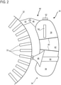
- the figure 2 shows the attachment of the oil tank 30 to a support casing 32 of the turbojet engine.
- it may be the casing 32 of the low pressure compressor which also supports an annular row of concentric blades 33.
- the turbojet engine may correspond to that of the figure 1 .
- the tank 30 is essentially elongated while matching the outer curvature of the support casing 32. This compactness allows installation between two closely spaced tubular walls.
- the tank 30 is partially filled with oil, or more precisely with a mixture of oil, air and impurities; such as abrasive metal particles loosened by wear.
- the tank 30 has an envelope 34 with, for example, a lower part 36 or first part 36, and an upper part 38 or second part 38. These parts (36; 38) can be connected by a weld 40, or via a part central 42 of the envelope 34; also called third part 42; which connects the lower part 36 to the upper part 38 via the welds 40.
- Each weld 40 can form a closed loop around the axis of general elongation of the tank. Thanks to its parts (36; 38; 42), the envelope 34, a real skin, defines a main chamber (not visible) forming an oil storage volume.
- the chamber is an internal chamber intended to be filled.
- the qualifier "main" of the main chamber is understood to mean that it is the largest receptacle of the reservoir 30.
- the tank 30 has a fixing portion 44 projecting with respect to the casing 34, for example towards the casing 32.
- This fixing portion 44 may comprise one or at least two flanges of fixing 46 (a visible flange hides the other). These flanges 46 can be integral with the lower part 36.
- the flanges 46 can be linked to thickenings of the partition 34 forming reinforced and spaced bases.
- the upper part 38 may have a fixing branch 48, for example linked to the casing 32 via a swivel arm 50.
- the branch 48 and the fixing flanges 46 can be linked to the casing 32 so as to allow isostatic fixing. . That is to say that they suppress respectively and only, one, two and three degrees of freedom when they are fixed to the complementary fixing means of the casing 32.
- the six degrees of freedom of the reservoir are thus fixed. This tends to reduce the effects of expansion, and limits internal stresses.
- Reservoir 30 may include other equipment. For example, it may include inlet and outlet orifices (not shown).
- a cap 52 can be placed in the upper part 38, for example at its top.
- a level viewing window 54 can be formed in the upper part 38.
- a drainer, a vent, and/or an oil separator (not shown) can be associated with the tank 30.
- Reservoir 30 is advantageously produced by additive manufacturing, at least partially.
- at least one part, such as the first part 36 and optionally the second part 38 are produced by additive manufacturing separately. They could be produced together in order to have come from matter.
- the third part 42 is optionally produced by additive manufacturing. Alternatively, it is formed by a sheet after rolling, for example of constant thickness. Its thickness may be less than the thickness of the casing 34 in the first and the second part.
- the thickness of the envelope 34 can vary between 2mm and 0.5mm, or from 1.5mm to 1mm.
- the fixing flanges 46 can be made in one piece with the lower part 36 of the casing 34, and in particular produced by additive manufacturing with the casing 34 in order to improve the connection between each flange and the casing 34 The addition of connecting radii again increases the transmission of forces there, and reduces the risk of fatigue cracks appearing.
- the tank 30 has a belt 56 on the outside. This connects the flanges 46 and forms a localized extra thickness on the casing 34.
- Each fixing flange 46 can generally describe a triangle.
- the opposite sides of the casing 32, ie towards the hollow of the curved shape of the tank 30, can be curved. This refines them, and makes it possible to lengthen them while preserving the lightness.
- the fixing ends of the fixing portion 44 are spaced from each other in order to increase the stability of the tank 30.
- the picture 3 has in section a zone where the envelope 34 forms a junction 58 which connects a fixing flange 46 to an internal stiffener 60 extending into the main chamber 62. Although only one flange 46 is shown, the present teaching can be applied to each flange 46 of the tank.
- the casing 34 becomes a spacer between the stiffener 60 and the flange 46 which extend towards the opposite of each other.
- the recessed sides 64 of the triangle formed by the flange 46 are in evidence; they can become tangent to the casing 34.
- a fixing hole 65 is visible in the flange 46.
- the figure 4 is a diagram of the manufacturing process of the oil tank such as that presented in relation to the preceding figures.
- step (a) design 100 different sectors are defined. These may be angular sectors. Their meeting can make it possible to produce the first envelope part and/or the second envelope part.
- Step (b) additive manufacturing 102 can be manufacturing by scanning a bed of powder by an electron beam, or by a laser beam. Step (b) additive manufacturing 102 is carried out in a pocket on a mobile plate of a machine where the powder bed is renewed then pre-compacted before solidification of the different layers superimposed. During this step, the powder can be preheated, for example to 700°C. The raw powder can have a particle size of 20 ⁇ m.
- Step (b) additive manufacturing 102 can be configured so as to generate a stack of layers of material. This stack, or superposition, can be oriented across or perpendicular to the thickness of the envelope part and the fixing portion, in particular where they meet. Layers can be visible in particles or crystals of matter. They can result from a thermal process, in particular from solidification.
- the figure 5 sketches an intermediate result of step (c) additive manufacturing of the process of the figure 4 . It shows a batch of 66 envelope sectors produced at the same time in an additive manufacturing machine. Sectors 66 are shown in section.
- This batch forms a block whose size optimizes the occupation of the manufacturing pocket of the additive manufacturing machine in order to increase the rate.
- the sectors 66 are nested one inside the other. These sectors 66 have concave surfaces and convex surfaces. In order to gain in compactness, the convex surfaces are in the concave surfaces by marrying each other. Flanges 46 and stiffener 60 can be fabricated outward from the block.
- the sectors 66 can be eighths of a sphere 68; possibly with a vertical extension 70.
Landscapes
- Engineering & Computer Science (AREA)
- Chemical & Material Sciences (AREA)
- General Engineering & Computer Science (AREA)
- Mechanical Engineering (AREA)
- Manufacturing & Machinery (AREA)
- Combustion & Propulsion (AREA)
- Materials Engineering (AREA)
- Physics & Mathematics (AREA)
- Plasma & Fusion (AREA)
- Structures Of Non-Positive Displacement Pumps (AREA)
- Powder Metallurgy (AREA)
Description
- L'invention concerne la fabrication d'un réservoir de turbomachine. Plus précisément, l'invention traite de la fabrication d'un réservoir métallique pour huile de turboréacteur. L'invention a également trait à une turbomachine axiale, notamment un turboréacteur d'avion ou un turbopropulseur d'aéronef. L'invention propose également un procédé de fabrication d'un réservoir
- La lubrification d'un turboréacteur repose sur une circulation continue d'huile. Cette huile emprunte un réseau dédié qui est connecté à un réservoir propre au turboréacteur. Ce réservoir forme à la fois le point de départ et l'arrivée du réseau. Par ailleurs, il offre un volume tampon qui compense une accumulation d'huile dans certaines zones, tout comme la consommation d'huile. Bien entendu, le réservoir doit rester fixé au turboréacteur malgré son niveau de remplissage et les vibrations.
- A toutes fins utiles, rappelons que l'huile d'un turboréacteur atteint 180°C, et même 230°C dans certains scénarios. En réponse à ces contraintes, le réservoir comme le circuit doivent être pensés de sorte à résister durablement à ces attaques. En outre, l'huile présente des propriétés corrosives, notamment en raison de la présence d'additifs indispensables dans un turboréacteur.
- Les documents
FR 2 485 630 A1 US 3 316 692 A divulguent un turboréacteur avec un carter supportant un réservoir d'huile à système antivibratoire. L'enveloppe du réservoir est traversée par un axe lié à des épaississements de l'enveloppe. Les extrémités de l'axe qui sortent de l'enveloppe forment des organes de fixation en prise souple avec le carter support du turboréacteur. L'axe forme un corps creux avec des collets usinés qui sont en contact des épaississements de l'enveloppe. En complément, une série de cloisons internes parallèles est liée à l'axe de manière à renforcer l'enveloppe. Un tel réservoir tend effectivement à montrer une certaine résistance aux vibrations, mais qui reste perfectible. - L'invention a pour objectif de résoudre au moins un des problèmes posés par l'art antérieur. Plus précisément, l'invention a pour objectif d'améliorer la résistance aux vibrations d'un réservoir d'huile de turboréacteur. L'invention a également pour objectif de proposer une solution simple, légère, économique, fiable, compacte, d'inspection aisée.
- L'invention a pour objet un réservoir de turboréacteur pour huile, le réservoir comprenant une chambre principale, une enveloppe délimitant la chambre principale, et une portion de fixation ; l'enveloppe comprenant une partie d'enveloppe par rapport à laquelle la portion de fixation fait saillie, notamment vers l'extérieur ; remarquable en ce que la partie d'enveloppe et la portion de fixation sont réalisées par fabrication additive par couches de sorte à être venues de matière.
- La caractéristique technique précisant que la partie d'enveloppe et la portion de fixation sont réalisées par fabrication additive par couches de sorte à être venues de matière, n'est pas une caractéristique essentielle de l'invention. Elle peut être remplacée par l'une des caractéristiques suivantes.
- Selon des modes particuliers de réalisation, le réservoir peut comprendre une ou plusieurs des caractéristiques suivantes, prises isolément ou selon toutes les combinaisons techniques possibles :
- La portion de fixation comprend une première bride de fixation faisant saillie par rapport à la cloison, et éventuellement une deuxième bride de fixation faisant saillie par rapport à l'enveloppe, l'enveloppe comprenant éventuellement un socle formant une surépaisseur sur la partie d'enveloppe au niveau d'au moins une ou de chaque bride.
- L'enveloppe présente une première zone de moindre épaisseur entre les deux brides de fixation et/ou à l'opposé des deux brides de fixation.
- Au moins une ou chacune des deux brides de fixation comprend un bord libre incurvé.
- Au moins une ou chacune des deux brides de fixation présente une forme de triangle, éventuellement asymétrique.
- Selon l'invention le réservoir comprend un raidisseur interne prolongeant la portion de fixation, notamment une bride de fixation, vers la chambre ; ledit raidisseur interne, la partie d'enveloppe et la portion de fixation étant réalisés par fabrication additive de sorte à être venus de matière.
- L'enveloppe comprend une extrémité avec une deuxième zone de moindre épaisseur, ladite extrémité étant éventuellement une extrémité inférieure du réservoir.
- L'enveloppe comprend une ceinture de renfort ou une portion de ceinture de renfort, la ceinture de renfort ou la portion de ceinture de renfort, la partie d'enveloppe et la portion de fixation sont réalisées par fabrication additive de sorte à être venues de matière.
- Le réservoir comprend au moins un équipement tel un évent, et/ou un désaérateur, et/ou un support de sonde, et/ou une crépine ; chaque équipement, la partie d'enveloppe et la portion de fixation étant réalisés par fabrication additive de sorte à être venus de matière.
- La partie d'enveloppe est une première partie d'enveloppe, l' enveloppe comprenant en outre une deuxième partie d'enveloppe réalisée par fabrication additive par couches et soudée à la première partie d'enveloppe selon une soudure.
- La chambre principale présente un allongement principal, la première soudure étant généralement perpendiculaire audit allongement principal.
- La première partie d'enveloppe forme un fond du réservoir et/ou la deuxième partie d'enveloppe forme un couvercle de réservoir.
- L'enveloppe comprend une face où la portion de fixation est disposée, et un amincissement à l'opposé de ladite face.
- La chambre principale présente une forme générale de cylindre, éventuellement courbé.
- Au moins une ou chacune des deux brides est jointe à la ceinture de renfort ou à la portion de ceinture de renfort.
- Au moins ou chacune des deux brides est une plaque, notamment du même matériau que l'enveloppe.
- Le raidisseur comprend un maillage occupant toute la chambre principale.
- La matière de la partie d'enveloppe et de la portion de fixation présente un empilement de couches de matière selon une direction d'empilement qui est transversale à l'épaisseur de ladite partie d'enveloppe.
- La partie d'enveloppe est monobloc.
- Le raidisseur traverse la chambre interne, éventuellement horizontalement.
- L'enveloppe comprend deux zones en surépaisseur qui sont chacune à la base d'une bride de fixation, et une troisième zone de moindre épaisseur séparant lesdites deux zones en surépaisseur.
- L'enveloppe est métallique, par exemple en acier.
- L'épaisseur minimale de l'enveloppe peut représenter moins de 75%, ou moins de 50%, ou moins de 25% de son épaisseur maximale. L'épaisseur maximale peut être mesurée en dehors des équipements, des brides, de la branche, du raidisseur, et éventuellement de la ceinture.
- La portion de fixation est une première portion de fixation venue de matière avec la première partie d'enveloppe par fabrication additive, et le réservoir comprend en outre une deuxième portion de fixation ; par exemple avec la branche ; qui est venue de matière avec la deuxième partie d'enveloppe par fabrication additive respectivement.
- L'invention a également pour objet un réservoir de turboréacteur, notamment pour huile, le réservoir comprenant une chambre principale, une enveloppe délimitant la chambre principale, et une portion de fixation ; l'enveloppe comprenant une partie d'enveloppe par rapport à laquelle la portion de fixation fait saillie, notamment vers l'extérieur ; remarquable en ce que la matière de la partie d'enveloppe et de la portion de fixation présente un empilement de couches de matière, notamment parallèles, selon une direction d'empilement qui est transversale à l'épaisseur de ladite partie d'enveloppe. Les couches peuvent s'observer dans la cristallographie de la matière.
- L'invention a également pour objet un réservoir de turboréacteur pour huile ; le réservoir comprenant une chambre principale intérieure, une enveloppe qui délimite la chambre principale, une portion de fixation externe, et un raidisseur interne prolongeant la portion de fixation dans la chambre principale ; remarquable en ce que l'enveloppe comprend une jonction réalisée par fabrication additive de sorte à ce que la portion de fixation, l'enveloppe et le raidisseur soient venus de matière.
- L'invention a également pour objet un turboréacteur comprenant un carter support et un réservoir d'huile avec une portion de fixation fixée au carter support, remarquable en ce que le réservoir d'huile est conforme à l'invention, préférentiellement le turboréacteur comprend circuit d'huile avec un palier et/ou un échangeur de chaleur, ledit circuit d 'huile communiquant avec ledit réservoir d'huile.
- Selon un mode avantageux de l'invention, le carter support comprend des moyens de fixation fixés à la portion de fixation de manière isostatique.
- L'invention a également pour objet un procédé de fabrication d'un réservoir d'huile de turboréacteur, le procédé comprenant une étape : (a) conception d'un réservoir d'huile avec une chambre principale, une enveloppe délimitant la chambre principale, et une portion de fixation ; l' enveloppe comprenant une partie d'où la portion de fixation fait saillie vers l'extérieur ; remarquable en ce qu'il comprend en outre une étape (b) fabrication additive par couches de la partie d'enveloppe et de la portion de fixation de sorte à être venues de matière, le réservoir étant éventuellement conforme à l'invention.
- Selon des modes particuliers de réalisation, le procédé peut comprendre une ou plusieurs des caractéristiques suivantes, prises isolément ou selon toutes les combinaisons techniques possibles :
- Lors de l'étape (b) fabrication additive la partie d'enveloppe est produite par secteurs dont un premier secteur avec une surface concave et un deuxième secteur avec une surface convexe ; lors de l'étape (b) fabrication additive la surface convexe est fabriquée dans la surface concave.
- Lors de l'étape (b) fabrication additive les deux secteurs d' enveloppe sont empilés suivant leurs épaisseurs.
- Lors de l'étape (b) fabrication additive les deux secteurs d' enveloppe sont écartés l'un de l'autre suivant leurs épaisseurs.
- Lors de l'étape (b) fabrication additive la surface convexe épouse la surface concave.
- La surface concave définit un volume interne dans lequel est fabriquée la surface convexe lors de l'étape (b) fabrication additive.
- L'enveloppe comprend une troisième partie, éventuellement formée par une tôle d'épaisseur constante soudée à une autre partie d' enveloppe.
- Le procédé comprend une étape (c) soudage des parties l'une à l' autre ou les unes aux autres.
- La fabrication additive par couches est à base de poudre, par exemple de titane ou d'inconel.
- La troisième partie est soudée entre la première partie d'enveloppe et la deuxième partie d'enveloppe.
- De manière générale, les modes avantageux de chaque objet de l'invention sont également applicables aux autres objets de l'invention. Dans la mesure du possible, chaque objet de l'invention est combinable aux autres objets. Les objets de l'invention sont également combinables aux modes de réalisation de la description, qui en plus sont combinables entre eux.
- L'invention permet de lier les fixations avec l'enveloppe grâce à une continuité de matière homogène. Cette homogénéité de matière améliore l'endurance du réservoir et favorise la transmission d'efforts de l'enveloppe aux portions de fixation. Dès lors, ces dernières participent à renforcer l'enveloppe tout en préservant une certaine élasticité. Cet aspect s'améliore à nouveau lorsque des raidisseurs prolongent les portions de fixation vers l'intérieur.
-
- La
figure 1 représente un turboréacteur selon l'invention. - La
figure 2 esquisse un carter de turboréacteur supportant un réservoir selon l'invention. - La
figure 3 illustre une jonction d'enveloppe de réservoir d'huile selon l'invention. - La
figure 4 présente un diagramme du procédé de fabrication du réservoir d'huile selon l'invention. - La
figure 5 montre un lot de secteurs d'enveloppe produit par fabrication additive selon l'invention. - Dans la description qui va suivre, les directions employées correspondent au sens normal de montage. L'intérieur du réservoir se réfère à sa chambre, et l'extérieur à son environnement.
- La
figure 1 représente de manière simplifiée une turbomachine axiale. Il s'agit dans ce cas précis d'un turboréacteur double-flux. Le turboréacteur 2 comprend un premier niveau de compression, dit compresseur basse pression 4, un deuxième niveau de compression, dit compresseur haute pression 6, une chambre de combustion 8 et un ou plusieurs niveaux de turbines 10. En fonctionnement, la puissance mécanique des turbines 10 transmise via des arbres 24 jusqu'au rotor 12 met en mouvement les deux compresseurs 4 et 6. Ces derniers comportent plusieurs rangées d'aubes de rotor associées à des rangées d'aubes de stators. La rotation du rotor autour de son axe de rotation 14 permet ainsi de générer un débit d'air et de comprimer progressivement ce dernier jusqu'à l'entrée dans la chambre de combustion 8. - Un ventilateur d'arrivée communément désigné fan ou soufflante 16 est couplé au rotor 12. Il génère un flux d'air qui se divise en un flux primaire 18, et un flux secondaire 20 traversant un conduit annulaire. Un réducteur épicycloïdal 22, peut réduire la vitesse de rotation de la soufflante 16 et/ou du compresseur basse pression 4 par rapport au niveau de turbine 10 associé.
- Le rotor 12 comporte plusieurs arbres 24 concentriques qui sont articulés de manière tournante via des paliers 26. Le refroidissement et/ou la lubrification sont assurés par un circuit d'huile. Ce circuit peut être propre au turboréacteur 2. Le circuit d'huile peut également comprendre un échangeur de chaleur 28 pour refroidir l'huile qui peut dépasser les 200°C, et même 230°C dans certains cas. Ces températures amplifient l'agressivité de l'huile corrosive vis-à-vis des joints et des parties polymères en général.
- La position et l'orientation du réservoir 30 sont ici figuratives. En pratique, ce réservoir 30 peut être fixé au carter du turboréacteur 2. Par exemple, il peut être lié au carter de soufflante 16, au carter du compresseur basse pression 4, ou au carter du compresseur haute pression 6. Ces implantations tendent à rajouter des contraintes thermiques, et l'exposent directement aux vibrations du turboréacteur, notamment en cas de perte de pale de soufflante.
- La
figure 2 présente la fixation du réservoir d'huile 30 à un carter support 32 du turboréacteur. En l'occurrence, il peut s'agir du carter 32 du compresseur basse pression qui supporte également une rangée annulaire d'aubes concentriques 33. Le turboréacteur peut correspondre à celui de lafigure 1 . - Afin d'augmenter son volume utile, le réservoir 30 est essentiellement allongé tout en épousant la courbure extérieure du carter support 32. Cette compacité permet une implantation entre deux parois tubulaires rapprochées. En fonctionnement, le réservoir 30 est partiellement rempli d'huile, ou plus précisément d'un mélange d'huile, d'air et d'impuretés ; telles des particules métalliques abrasives relâchées par l'usure.
- Le réservoir 30 présente une enveloppe 34 avec, par exemple, une partie inférieure 36 ou première partie 36, et une partie supérieure 38 ou deuxième partie 38. Ces parties (36 ; 38) peuvent être reliées par une soudure 40, ou via une partie centrale 42 de l'enveloppe 34 ; également appelée troisième partie 42 ; qui relie la partie inférieure 36 à la partie supérieure 38 via les soudures 40. Chaque soudure 40 peut former une boucle fermée autour de l'axe d'allongement général du réservoir. Grâce à ses parties (36 ; 38 ; 42), l'enveloppe 34, véritable peau, définit une chambre principale (non visible) formant un volume de stockage d'huile. La chambre est une chambre interne destine à être remplie. Le qualificatif « principal » de la chambre principale est entendu dans le sens où il s'agit du plus grand réceptacle du réservoir 30.
- En matière de montage sur le carter support 32, le réservoir 30 montre une portion de fixation 44 faisant saillie par rapport à l'enveloppe 34, par exemple vers le carter 32. Cette portion de fixation 44 peut comprendre une ou au moins deux brides de fixation 46 (une bride visible cache l'autre). Ces brides 46 peuvent être solidaires de la partie inférieure 36. Les brides 46 peuvent être liées à des épaississements de la cloison 34 formant des socles renforcés et écartés. De son côté, la partie supérieure 38 peut présenter une branche de fixation 48, par exemple liée au carter 32 via un bras rotulé 50. La branche 48 et les brides de fixation 46 peuvent être liées au carter 32 de sorte à permettre une fixation isostatique. C'est à-dire qu'elles suppriment respectivement et uniquement, un, deux et trois degrés de liberté lorsqu'elles sont fixées aux moyens de fixation complémentaires du carter 32. Les six degrés de liberté du réservoir sont ainsi figés. Ceci tend à réduire les effets de la dilatation, et limite les contraintes internes.
- Le réservoir 30 peut comprendre d'autres équipements. Par exemple, il peut comprendre des orifices d'entrée et de sortie (non représentés). Un bouchon 52 peut être placé en partie supérieure 38, par exemple à son sommet. Une fenêtre de visualisation 54 du niveau peut être formée dans la partie supérieure 38. Un déserteur, un évent, et/ou un déshuileur (non représentés) peuvent être associés au réservoir 30.
- Le réservoir 30 est avantageusement produit par fabrication additive, au moins partiellement. Par exemple au moins une partie, telle la première partie 36 et éventuellement la deuxième partie 38 sont produites par fabrication additive de manière séparée. Elles pourraient être produites ensemble afin d'être venues de matière. La troisième partie 42 est optionnellement produite par fabrication additive. En variante, elle est formée par une tôle issue de laminage, par exemple d'épaisseur constante. Son épaisseur peut être inférieure à l'épaisseur de l'enveloppe 34 dans la première et la deuxième partie. L'épaisseur de l'enveloppe 34 peut varier entre 2mm et 0,5mm, ou de 1,5mm à 1mm.
- En outre, les brides de fixations 46 peuvent être venues de matière avec la partie inférieure 36 de l'enveloppe 34, et en particulier produites par fabrication additive avec l'enveloppe 34 afin d'améliorer la liaison entre chaque bride et l'enveloppe 34. L'ajout de rayons de raccordement y augmente à nouveau la transmission d'efforts, et réduit le risque d'apparition de fissures par fatigue. Optionnellement, le réservoir 30 présente une ceinture 56 à l'extérieur. Celle-ci relie les brides 46 et forme une surépaisseur localisée sur l'enveloppe 34.
- Chaque bride de fixation 46 peut généralement décrire un triangle. Les côtés en regard du carter 32, soit vers le creux de la forme courbée du réservoir 30, peuvent être incurvés. Ceci les affine, et permet de les allonger tout en préservant la légèreté. Par ailleurs, les extrémités de fixation de la portion de fixation 44 sont écartées les unes des autres afin d'accroitre la stabilité du réservoir 30.
- La
figure 3 présente en coupe une zone où l'enveloppe 34 forme une jonction 58 qui relie une bride de fixation 46 à un raidisseur interne 60 s'étendant dans la chambre principale 62. Bien qu'une seule bride 46 ne soit représentée, le présent enseignement peut s'appliquer à chaque bride 46 du réservoir. - L'enveloppe 34 devient un intercalaire entre le raidisseur 60 et la bride 46 qui s'étendent vers l'opposé l'un de l'autre. Les côtés 64 en creux du triangle que forme la bride 46 sont en évidence ; ils peuvent devenir tangents à l'enveloppe 34. Un orifice de fixation 65 est visible dans la bride 46.
- La
figure 4 est un diagramme du procédé de fabrication du réservoir d'huile tel que celui présenté en relation avec les figures précédentes. - Le procédé peut comprendre les étapes suivantes, éventuellement réalisées dans l'ordre introduit ci-dessous :
- (a) conception 100 d'un réservoir d'huile de turboréacteur en prenant en compte une durée de vie d'au moins 25 ans et des contraintes de fonctionnement ;
- (b) fabrication additive 102 par couches à base de poudre d'au moins une, ou d'au moins deux, ou de chaque partie d'enveloppe, et de la portion de fixation ;
- (c) soudage 104 des parties l'une à l'autre ou les unes aux autres ;
- (d) finition 106 du réservoir, dont le sablage et le traitement de l'enveloppe ; cette étape (d) finition 106 restant entièrement optionnelle.
- Lors de l'étape (a) conception 100, différents secteurs sont définis. Il peut s'agir de secteurs angulaires. Leur réunuion peut permettre de réaliser la première partie d'enveloppe et/ou la deuxième partie d'enveloppe.
- L'étape (b) fabrication additive 102 peut être une fabrication par balayage d'un lit de poudre par un faisceau d'électrons, ou par un rayon laser. L'étape (b) fabrication additive 102 est effectuée dans une poche sur un plateau mobile d'une machine où le lit de poudre est renouvelé puis précompacté avant solidification des différentes couches superposées. Lors de cette étape, la poudre peut être préchauffée, par exemple à 700°C. La poudre brute peut avoir une granulométrie de 20µm.
- L'étape (b) fabrication additive 102 peut être configurée de manière à générer un empilement de couches de matière. Cet empiliment, ou superposition, peut être orienté de traver, ou perpendiculairement à l'épaisseur de la partie d'enveloppe et à la portion de fixation, notamment là où elles se réunissent. Les couches peuvent être visibles dans les particules ou les cristaux de matières. Elles peuvent résulter d'un processus thermique, notamment d'une solidification.
- La
figure 5 esquisse un résultat intermédiaire de l'étape (c) fabrication additive du procédé de lafigure 4 . Elle montre un lot de secteurs 66 d'enveloppe produit en même temps dans une machine de fabrication additive. Les secteurs 66 sont représentés en coupe. - Ce lot forme un bloc dont la taille optimise l'occupation de la poche de fabrication de la machine de fabrication additive afin d'augmenter la cadence. Dans ce bloc, les secteurs 66 sont imbriqués les uns dans les autres. Ces secteurs 66 présentent des surfaces concaves et des surfaces convexes. Afin de gagner en compacité, les surfaces convexes sont dans les surfaces concaves en s'épousant les unes les autres. Les brides 46 et le raidisseur 60 peuvent être fabriqués vers l'extérieur du bloc.
- Les secteurs 66 peuvent être des huitièmes de sphère 68 ; éventuellement avec un prolongement vertical 70.
Claims (14)
- Réservoir (30) de turboréacteur (2) pour huile, le réservoir (30) comprenant une chambre principale (62), une enveloppe (34) délimitant la chambre principale (62), et une portion de fixation (44) ; l'enveloppe (34) comprenant une partie (36 ; 38) d'enveloppe par rapport à laquelle la portion de fixation (44) fait saillie, notamment vers l'extérieur de la chambre;
caractérisé en ce que
la partie (36 ; 38) d'enveloppe et la portion de fixation (44) sont réalisées par fabrication additive par couches de sorte à être venues de matière, et en ce que le réservoir comprend un raidisseur interne (60) prolongeant la portion de fixation (44), notamment une bride de fixation (46), vers la chambre principale (62) ; ledit raidisseur interne (60), la partie (36 ; 38) d'enveloppe (34) et la portion de fixation (44) étant réalisés par fabrication additive de sorte à être venus de matière. - Réservoir (30) selon la revendication 1, caractérisé en ce que la portion de fixation (44) comprend une première bride de fixation (46) faisant saillie par rapport à la cloison, et éventuellement une deuxième bride de fixation (46) faisant saillie par rapport à l'enveloppe (34), l'enveloppe (34) comprenant éventuellement un socle formant une surépaisseur sur la partie (36 ; 38) d'enveloppe (34) au niveau d'au moins une ou de chaque bride (46).
- Réservoir (30) selon la revendication 2, caractérisé en ce que l'enveloppe (34) présente une première zone de moindre épaisseur entre les deux brides de fixation (46) et/ou à l'opposé des deux brides de fixation (46).
- Réservoir (30) selon l'une des revendications 2 à 3, caractérisé en ce qu'au moins une ou chacune des deux brides de fixation (46) comprend un bord (64) libre incurvé, et/ou au moins une ou chacune des deux brides de fixation (46) présente une forme de triangle, éventuellement asymétrique.
- Réservoir (30) selon l'une des revendications 1 à 4, caractérisé en ce que la matière de la partie (36 ; 38) d'enveloppe et de la portion de fixation (44) présente un empilement de couches de matière selon une direction d'empilement qui est transversale à l'épaisseur de ladite partie d'enveloppe (34).
- Réservoir (30) selon l'une des revendications 1 à 5, caractérisé en ce que l'enveloppe (34) comprend une ceinture de renfort (56) ou une portion de ceinture de renfort, la ceinture de renfort (56) ou la portion de ceinture de renfort, la partie (36 ; 38) d'enveloppe et la portion de fixation (44) sont réalisées par fabrication additive de sorte à être venues de matière.
- Réservoir (30) selon l'une des revendications 1 à 6, caractérisé en ce que la partie d'enveloppe est une première partie (36) d'enveloppe, l'enveloppe (34) comprenant en outre une deuxième partie (38) d'enveloppe réalisée par fabrication additive par couches et soudée à la première partie (36) d'enveloppe selon une soudure (40).
- Réservoir (30) selon la revendication 7, caractérisé en ce que la première partie (36) d'enveloppe forme un fond du réservoir (30) et/ou la deuxième partie (38) d'enveloppe forme un couvercle de réservoir (30).
- Réservoir (30) de turboréacteur (2) pour huile, le réservoir (30) comprenant une chambre principale (62), une enveloppe (34) délimitant la chambre principale (62), et une portion de fixation (44) ; l'enveloppe (34) comprenant une partie (36 ; 38) d'enveloppe par rapport à laquelle la portion de fixation (44) fait saillie, notamment vers l'extérieur de la chambre;
caractérisé en ce que
la matière de la partie (36 ; 38) d'enveloppe et de la portion de fixation (44) comprennent un empilement de couches avec une direction d'empilement des couches qui est transversale à l'épaisseur de l'enveloppe (34) ; le réservoir étant éventuellement conforme à l'une des revendications 1 à 8. - Turboréacteur (2) comprenant un carter support (32) et un réservoir (30) d'huile avec une portion de fixation (44) fixée au carter support (32), caractérisé en ce que le réservoir d'huile (30) est conforme à l'une des revendications 1 à 9, préférentiellement le turboréacteur (2) comprend circuit d'huile avec un palier (26) et/ou un échangeur de chaleur (28), ledit circuit d'huile communiquant avec ledit réservoir d'huile (30), et/ou le carter support (32) comprend des moyens de fixation fixés à la portion de fixation (44) de manière isostatique.
- Procédé de fabrication d'un réservoir (30) d'huile de turboréacteur (2), le procédé comprenant une étape :(a) conception (100) d'un réservoir (30) d'huile avec une chambre principale (62), une enveloppe (34) délimitant la chambre principale (62), et une portion de fixation (44); l'enveloppe (34) comprenant une partie (36 ; 38) d'où la portion de fixation (44) fait saillie vers l'extérieur ;caractérisé en ce qu'il comprend en outre une étape
(b) fabrication additive (102) par couches de la partie (36; 38) d'enveloppe et de la portion de fixation (44) de sorte à être venues de matière, le réservoir (30) étant conforme à l'une des revendications 1 à 9. - Procédé selon la revendication 11, caractérisé en ce que lors de l'étape (b) fabrication additive (102) la partie (36 ; 38) d'enveloppe est produite par secteurs (66) dont un premier secteur (66) avec une surface concave et un deuxième secteur (66) avec une surface convexe ; lors de l'étape (b) fabrication additive la surface convexe est fabriquée dans la surface concave.
- Procédé selon l'une des revendications 11 à 12, caractérisé en ce que l'enveloppe (34) comprend une troisième partie (42), éventuellement formée par une tôle d'épaisseur constante soudée à une autre partie d'enveloppe (36 ; 38).
- Procédé selon l'une des revendications 11 à 13, caractérisé en ce qu'il comprend une étape (c) soudage (104) des parties (36 ; 38 ; 42) l'une à l'autre ou les unes aux autres.
Applications Claiming Priority (1)
| Application Number | Priority Date | Filing Date | Title |
|---|---|---|---|
| BE2016/5768A BE1024639B1 (fr) | 2016-10-13 | 2016-10-13 | Reservoir d'huile de turbomachine |
Publications (2)
| Publication Number | Publication Date |
|---|---|
| EP3308960A1 EP3308960A1 (fr) | 2018-04-18 |
| EP3308960B1 true EP3308960B1 (fr) | 2022-03-02 |
Family
ID=57184272
Family Applications (1)
| Application Number | Title | Priority Date | Filing Date |
|---|---|---|---|
| EP17194670.0A Active EP3308960B1 (fr) | 2016-10-13 | 2017-10-04 | Réservoir d'huile de turbomachine |
Country Status (5)
| Country | Link |
|---|---|
| US (1) | US10914198B2 (fr) |
| EP (1) | EP3308960B1 (fr) |
| CN (1) | CN107939527B (fr) |
| BE (1) | BE1024639B1 (fr) |
| CA (1) | CA2982036C (fr) |
Families Citing this family (3)
| Publication number | Priority date | Publication date | Assignee | Title |
|---|---|---|---|---|
| CN111895259B (zh) * | 2020-07-10 | 2021-11-12 | 中国航发湖南动力机械研究所 | 集成式储油箱 |
| US11674414B2 (en) * | 2021-03-19 | 2023-06-13 | Pratt & Whitney Canada Corp. | Gas turbine engine and mount assembly therefor |
| US20240343405A1 (en) * | 2023-04-11 | 2024-10-17 | Pratt & Whitney Canada Corp. | Externally-mounted aircraft engine component |
Family Cites Families (36)
| Publication number | Priority date | Publication date | Assignee | Title |
|---|---|---|---|---|
| US2364119A (en) * | 1943-02-26 | 1944-12-05 | Cons Vultee Aircraft Corp | Oil tank for airplane engines |
| US2604188A (en) * | 1949-08-19 | 1952-07-22 | A V Roe Canada Ltd | Oil supply and scavenge system |
| US2902240A (en) * | 1955-07-11 | 1959-09-01 | Gen Motors Corp | Mounting means |
| US3027971A (en) * | 1960-04-13 | 1962-04-03 | Jr Albert E Ketler | Engine lubrication system |
| US3316692A (en) * | 1965-12-15 | 1967-05-02 | United Aircraft Prod | Liquid storage tank |
| US3771287A (en) * | 1972-10-02 | 1973-11-13 | United Aircraft Corp | Deaerating oil tank |
| DE2743994C3 (de) * | 1977-09-30 | 1980-04-24 | Mtu Motoren- Und Turbinen-Union Muenchen Gmbh, 8000 Muenchen | Einrichtung zur Entlüftung von Flüssigkeitsbehältern für Flugzeuge |
| GB2059517B (en) * | 1979-09-29 | 1983-06-22 | Rolls Royce | Lubrication system |
| FR2485630A1 (fr) * | 1980-06-30 | 1981-12-31 | Snecma | Reservoir a suspension antivibratoire |
| DE3047719C2 (de) * | 1980-12-18 | 1983-10-27 | MTU Motoren- und Turbinen-Union München GmbH, 8000 München | Einrichtung zur Entlüftung eines Flüssigkeitsbehälters, insbesondere eines Schmiermittelbehälters für Flugzeuge bei extremen Fluglagen und -bedingungen |
| US5185018A (en) * | 1991-11-04 | 1993-02-09 | Zievers Elizabeth S | Structural fibrosics |
| US6793042B2 (en) * | 2002-07-24 | 2004-09-21 | Pratt & Whitney Canada Corp. | Dual independent tank and oil system with single port filling |
| US8104736B2 (en) * | 2005-12-01 | 2012-01-31 | Hamilton Sundstrand Corporation | Gas turbine engine auxiliary component mount |
| WO2008031195A1 (fr) * | 2006-09-14 | 2008-03-20 | Pratt & Whitney Canada Corp. | Logement d'accès pour moteur de turbine à gaz |
| US8020665B2 (en) * | 2006-11-22 | 2011-09-20 | United Technologies Corporation | Lubrication system with extended emergency operability |
| US8272527B2 (en) * | 2007-07-10 | 2012-09-25 | Cnh America Llc | Latching assembly for a pressurized tank cover |
| US8201664B2 (en) * | 2008-01-23 | 2012-06-19 | Pratt & Whitney Canada Corp. | Lubrication system and method, and vortex flow separator for use therewith |
| US8893856B2 (en) * | 2008-07-24 | 2014-11-25 | Honeywell International Inc. | Gravity scavenged generator with integral engine oil tank |
| DE102009034566B4 (de) * | 2009-07-23 | 2017-03-30 | Airbus Defence and Space GmbH | Verfahren zum Herstellen eines Tanks für Treibstoff |
| US8366809B2 (en) * | 2011-03-14 | 2013-02-05 | Hamilton Sundstrand Corporation | Deaerating method and assembly |
| US20130180994A1 (en) * | 2011-12-12 | 2013-07-18 | Ingrid McTaggart | Molded fuel tank and method of manufacturing the same |
| GB2498006B (en) * | 2011-12-22 | 2014-07-09 | Rolls Royce Plc | Gas turbine engine systems |
| JP5803680B2 (ja) * | 2012-01-05 | 2015-11-04 | スズキ株式会社 | 車両用バイフューエルエンジン |
| US10023322B2 (en) * | 2012-01-30 | 2018-07-17 | Neal Keefer | Molded fuel tank and method of manufacturing the same |
| US8985278B2 (en) * | 2012-09-07 | 2015-03-24 | United Technologies Corporation | Lubrication system having segmented anti-backflow feature |
| WO2014076315A2 (fr) * | 2012-11-19 | 2014-05-22 | Castrol Limited | Système de réservoir de fluide |
| EP2808595B1 (fr) * | 2013-05-27 | 2018-11-21 | Safran Aero Boosters SA | Réservoir et procédé pour sa fabrication |
| EP3014496B1 (fr) * | 2013-06-28 | 2019-12-11 | United Technologies Corporation | Procédé de fabrication additive |
| EP3564511A1 (fr) * | 2013-10-29 | 2019-11-06 | United Technologies Corporation | Agencement de montage de réservoir d'huile sur un moteur à double flux à engrenage |
| BR112016009534B1 (pt) * | 2013-11-06 | 2021-05-25 | Hutchinson | dispositivo de ligação para tubagem de transmissão de fluido de uma aeronave ou de um veículo espacial, tubo para transmissão do fluido e método para produção de um dispositivo de ligação |
| GB201400795D0 (en) * | 2014-01-17 | 2014-03-05 | Rolls Royce Plc | Oil system |
| DE102014102776A1 (de) * | 2014-03-03 | 2015-09-03 | Rolls-Royce Deutschland Ltd & Co Kg | Baueinheit zur Anordnung an einem Hydraulikfluidtank eines Strahltriebwerks |
| DE102014113128A1 (de) * | 2014-09-11 | 2016-03-17 | Rolls-Royce Deutschland Ltd & Co Kg | Tankvorrichtung eines Flugtriebwerks mit einer Einrichtung zum Einleiten von Öl |
| US10578020B2 (en) * | 2015-07-21 | 2020-03-03 | Unison Industries, Llc | Integral oil tank heat exchanger |
| BE1024640B1 (fr) * | 2016-10-13 | 2018-05-16 | Safran Aero Boosters S.A. | Procede de fabrication additive de reservoir d'huile de turbomachine |
| BE1025191B1 (fr) * | 2017-05-03 | 2018-12-06 | Safran Aero Boosters S.A. | Reservoir a sonde de niveau d’huile pour turbomachine |
-
2016
- 2016-10-13 BE BE2016/5768A patent/BE1024639B1/fr not_active IP Right Cessation
-
2017
- 2017-10-04 EP EP17194670.0A patent/EP3308960B1/fr active Active
- 2017-10-09 US US15/727,796 patent/US10914198B2/en active Active
- 2017-10-11 CN CN201710940846.7A patent/CN107939527B/zh active Active
- 2017-10-11 CA CA2982036A patent/CA2982036C/fr active Active
Also Published As
| Publication number | Publication date |
|---|---|
| BE1024639A1 (fr) | 2018-05-09 |
| CN107939527A (zh) | 2018-04-20 |
| US10914198B2 (en) | 2021-02-09 |
| EP3308960A1 (fr) | 2018-04-18 |
| CA2982036C (fr) | 2023-01-03 |
| US20180128128A1 (en) | 2018-05-10 |
| CA2982036A1 (fr) | 2018-04-13 |
| BE1024639B1 (fr) | 2018-05-16 |
| CN107939527B (zh) | 2021-09-07 |
Similar Documents
| Publication | Publication Date | Title |
|---|---|---|
| EP3064708B1 (fr) | Aube composite de compresseur de turbomachine axiale avec une feuille de renfort et turbomachine comprenant une telle aube | |
| BE1024941B1 (fr) | Controle actif de jeu pour compresseur de turbomachine | |
| CA2889751C (fr) | Moyeu de carter d'echappement pour une turbomachine | |
| FR3071008A1 (fr) | Aube directrice de sortie pour turbomachine, comprenant un passage de refroidissement de lubrifiant equipe d'une matrice de conduction thermique comprimee entre les parois d'intrados et d'extrados | |
| FR2963068A1 (fr) | Manchon protecteur pour composant de turbine | |
| EP3456933B1 (fr) | Groupe de lubrification pour turbomachine, turbomachine et procédé de fabrication d'une groupe de lubrification | |
| EP3521569B1 (fr) | Carter structural pour turbomachine axiale | |
| WO2016142631A1 (fr) | Réalisation de demi-etages de redresseurs monoblocs, par fabrication additive | |
| FR3027071A1 (fr) | Procede d'intervention sur un rotor et clinquant associe | |
| EP3308881B1 (fr) | Procédé de fabrication additive de réservoir d'huile de turbomachine | |
| BE1023619A1 (fr) | Carter de compresseur de turbomachine axiale | |
| EP3091201B1 (fr) | Bec de séparation composite de compresseur de turbomachine axiale | |
| EP2896796A1 (fr) | Stator de turbomachine axiale et turbomachine associée | |
| EP3308960A1 (fr) | Réservoir d'huile de turbomachine | |
| BE1025642B1 (fr) | Carter de compresseur avec reservoir d'huile pour turbomachine | |
| EP3833854A1 (fr) | Carter interne de turbomachine à isolation thermique améliorée | |
| EP3382242B1 (fr) | Joint à brosse pour rotor de turbomachine | |
| EP3918185A1 (fr) | Secteur de stator de turbomachine a zones soumises a des contraintes élevées assouplies | |
| WO2019228897A1 (fr) | Virole a profilage évolutif pour compresseur de turbomachine | |
| BE1023031B1 (fr) | Bec de separation composite de compresseur de turbomachine axiale | |
| BE1024829B1 (fr) | Aube rugueuse pour compresseur de turbomachine axiale |
Legal Events
| Date | Code | Title | Description |
|---|---|---|---|
| PUAI | Public reference made under article 153(3) epc to a published international application that has entered the european phase |
Free format text: ORIGINAL CODE: 0009012 |
|
| STAA | Information on the status of an ep patent application or granted ep patent |
Free format text: STATUS: THE APPLICATION HAS BEEN PUBLISHED |
|
| AK | Designated contracting states |
Kind code of ref document: A1 Designated state(s): AL AT BE BG CH CY CZ DE DK EE ES FI FR GB GR HR HU IE IS IT LI LT LU LV MC MK MT NL NO PL PT RO RS SE SI SK SM TR |
|
| AX | Request for extension of the european patent |
Extension state: BA ME |
|
| STAA | Information on the status of an ep patent application or granted ep patent |
Free format text: STATUS: REQUEST FOR EXAMINATION WAS MADE |
|
| 17P | Request for examination filed |
Effective date: 20181016 |
|
| RBV | Designated contracting states (corrected) |
Designated state(s): AL AT BE BG CH CY CZ DE DK EE ES FI FR GB GR HR HU IE IS IT LI LT LU LV MC MK MT NL NO PL PT RO RS SE SI SK SM TR |
|
| GRAP | Despatch of communication of intention to grant a patent |
Free format text: ORIGINAL CODE: EPIDOSNIGR1 |
|
| STAA | Information on the status of an ep patent application or granted ep patent |
Free format text: STATUS: GRANT OF PATENT IS INTENDED |
|
| INTG | Intention to grant announced |
Effective date: 20210913 |
|
| GRAS | Grant fee paid |
Free format text: ORIGINAL CODE: EPIDOSNIGR3 |
|
| GRAA | (expected) grant |
Free format text: ORIGINAL CODE: 0009210 |
|
| STAA | Information on the status of an ep patent application or granted ep patent |
Free format text: STATUS: THE PATENT HAS BEEN GRANTED |
|
| AK | Designated contracting states |
Kind code of ref document: B1 Designated state(s): AL AT BE BG CH CY CZ DE DK EE ES FI FR GB GR HR HU IE IS IT LI LT LU LV MC MK MT NL NO PL PT RO RS SE SI SK SM TR |
|
| REG | Reference to a national code |
Ref country code: GB Ref legal event code: FG4D Free format text: NOT ENGLISH |
|
| REG | Reference to a national code |
Ref country code: CH Ref legal event code: EP Ref country code: AT Ref legal event code: REF Ref document number: 1471925 Country of ref document: AT Kind code of ref document: T Effective date: 20220315 |
|
| REG | Reference to a national code |
Ref country code: DE Ref legal event code: R096 Ref document number: 602017053953 Country of ref document: DE |
|
| REG | Reference to a national code |
Ref country code: IE Ref legal event code: FG4D Free format text: LANGUAGE OF EP DOCUMENT: FRENCH |
|
| REG | Reference to a national code |
Ref country code: LT Ref legal event code: MG9D |
|
| REG | Reference to a national code |
Ref country code: NL Ref legal event code: MP Effective date: 20220302 |
|
| PG25 | Lapsed in a contracting state [announced via postgrant information from national office to epo] |
Ref country code: SE Free format text: LAPSE BECAUSE OF FAILURE TO SUBMIT A TRANSLATION OF THE DESCRIPTION OR TO PAY THE FEE WITHIN THE PRESCRIBED TIME-LIMIT Effective date: 20220302 Ref country code: RS Free format text: LAPSE BECAUSE OF FAILURE TO SUBMIT A TRANSLATION OF THE DESCRIPTION OR TO PAY THE FEE WITHIN THE PRESCRIBED TIME-LIMIT Effective date: 20220302 Ref country code: NO Free format text: LAPSE BECAUSE OF FAILURE TO SUBMIT A TRANSLATION OF THE DESCRIPTION OR TO PAY THE FEE WITHIN THE PRESCRIBED TIME-LIMIT Effective date: 20220602 Ref country code: LT Free format text: LAPSE BECAUSE OF FAILURE TO SUBMIT A TRANSLATION OF THE DESCRIPTION OR TO PAY THE FEE WITHIN THE PRESCRIBED TIME-LIMIT Effective date: 20220302 Ref country code: HR Free format text: LAPSE BECAUSE OF FAILURE TO SUBMIT A TRANSLATION OF THE DESCRIPTION OR TO PAY THE FEE WITHIN THE PRESCRIBED TIME-LIMIT Effective date: 20220302 Ref country code: ES Free format text: LAPSE BECAUSE OF FAILURE TO SUBMIT A TRANSLATION OF THE DESCRIPTION OR TO PAY THE FEE WITHIN THE PRESCRIBED TIME-LIMIT Effective date: 20220302 Ref country code: BG Free format text: LAPSE BECAUSE OF FAILURE TO SUBMIT A TRANSLATION OF THE DESCRIPTION OR TO PAY THE FEE WITHIN THE PRESCRIBED TIME-LIMIT Effective date: 20220602 |
|
| REG | Reference to a national code |
Ref country code: AT Ref legal event code: MK05 Ref document number: 1471925 Country of ref document: AT Kind code of ref document: T Effective date: 20220302 |
|
| PG25 | Lapsed in a contracting state [announced via postgrant information from national office to epo] |
Ref country code: PL Free format text: LAPSE BECAUSE OF FAILURE TO SUBMIT A TRANSLATION OF THE DESCRIPTION OR TO PAY THE FEE WITHIN THE PRESCRIBED TIME-LIMIT Effective date: 20220302 Ref country code: LV Free format text: LAPSE BECAUSE OF FAILURE TO SUBMIT A TRANSLATION OF THE DESCRIPTION OR TO PAY THE FEE WITHIN THE PRESCRIBED TIME-LIMIT Effective date: 20220302 Ref country code: GR Free format text: LAPSE BECAUSE OF FAILURE TO SUBMIT A TRANSLATION OF THE DESCRIPTION OR TO PAY THE FEE WITHIN THE PRESCRIBED TIME-LIMIT Effective date: 20220603 Ref country code: FI Free format text: LAPSE BECAUSE OF FAILURE TO SUBMIT A TRANSLATION OF THE DESCRIPTION OR TO PAY THE FEE WITHIN THE PRESCRIBED TIME-LIMIT Effective date: 20220302 |
|
| PG25 | Lapsed in a contracting state [announced via postgrant information from national office to epo] |
Ref country code: NL Free format text: LAPSE BECAUSE OF FAILURE TO SUBMIT A TRANSLATION OF THE DESCRIPTION OR TO PAY THE FEE WITHIN THE PRESCRIBED TIME-LIMIT Effective date: 20220302 |
|
| PG25 | Lapsed in a contracting state [announced via postgrant information from national office to epo] |
Ref country code: SM Free format text: LAPSE BECAUSE OF FAILURE TO SUBMIT A TRANSLATION OF THE DESCRIPTION OR TO PAY THE FEE WITHIN THE PRESCRIBED TIME-LIMIT Effective date: 20220302 Ref country code: SK Free format text: LAPSE BECAUSE OF FAILURE TO SUBMIT A TRANSLATION OF THE DESCRIPTION OR TO PAY THE FEE WITHIN THE PRESCRIBED TIME-LIMIT Effective date: 20220302 Ref country code: RO Free format text: LAPSE BECAUSE OF FAILURE TO SUBMIT A TRANSLATION OF THE DESCRIPTION OR TO PAY THE FEE WITHIN THE PRESCRIBED TIME-LIMIT Effective date: 20220302 Ref country code: PT Free format text: LAPSE BECAUSE OF FAILURE TO SUBMIT A TRANSLATION OF THE DESCRIPTION OR TO PAY THE FEE WITHIN THE PRESCRIBED TIME-LIMIT Effective date: 20220704 Ref country code: EE Free format text: LAPSE BECAUSE OF FAILURE TO SUBMIT A TRANSLATION OF THE DESCRIPTION OR TO PAY THE FEE WITHIN THE PRESCRIBED TIME-LIMIT Effective date: 20220302 Ref country code: CZ Free format text: LAPSE BECAUSE OF FAILURE TO SUBMIT A TRANSLATION OF THE DESCRIPTION OR TO PAY THE FEE WITHIN THE PRESCRIBED TIME-LIMIT Effective date: 20220302 Ref country code: AT Free format text: LAPSE BECAUSE OF FAILURE TO SUBMIT A TRANSLATION OF THE DESCRIPTION OR TO PAY THE FEE WITHIN THE PRESCRIBED TIME-LIMIT Effective date: 20220302 |
|
| PG25 | Lapsed in a contracting state [announced via postgrant information from national office to epo] |
Ref country code: IS Free format text: LAPSE BECAUSE OF FAILURE TO SUBMIT A TRANSLATION OF THE DESCRIPTION OR TO PAY THE FEE WITHIN THE PRESCRIBED TIME-LIMIT Effective date: 20220702 Ref country code: AL Free format text: LAPSE BECAUSE OF FAILURE TO SUBMIT A TRANSLATION OF THE DESCRIPTION OR TO PAY THE FEE WITHIN THE PRESCRIBED TIME-LIMIT Effective date: 20220302 |
|
| REG | Reference to a national code |
Ref country code: DE Ref legal event code: R097 Ref document number: 602017053953 Country of ref document: DE |
|
| PLBE | No opposition filed within time limit |
Free format text: ORIGINAL CODE: 0009261 |
|
| STAA | Information on the status of an ep patent application or granted ep patent |
Free format text: STATUS: NO OPPOSITION FILED WITHIN TIME LIMIT |
|
| PG25 | Lapsed in a contracting state [announced via postgrant information from national office to epo] |
Ref country code: DK Free format text: LAPSE BECAUSE OF FAILURE TO SUBMIT A TRANSLATION OF THE DESCRIPTION OR TO PAY THE FEE WITHIN THE PRESCRIBED TIME-LIMIT Effective date: 20220302 |
|
| 26N | No opposition filed |
Effective date: 20221205 |
|
| PG25 | Lapsed in a contracting state [announced via postgrant information from national office to epo] |
Ref country code: SI Free format text: LAPSE BECAUSE OF FAILURE TO SUBMIT A TRANSLATION OF THE DESCRIPTION OR TO PAY THE FEE WITHIN THE PRESCRIBED TIME-LIMIT Effective date: 20220302 |
|
| PG25 | Lapsed in a contracting state [announced via postgrant information from national office to epo] |
Ref country code: MC Free format text: LAPSE BECAUSE OF FAILURE TO SUBMIT A TRANSLATION OF THE DESCRIPTION OR TO PAY THE FEE WITHIN THE PRESCRIBED TIME-LIMIT Effective date: 20220302 |
|
| REG | Reference to a national code |
Ref country code: CH Ref legal event code: PL |
|
| PG25 | Lapsed in a contracting state [announced via postgrant information from national office to epo] |
Ref country code: LU Free format text: LAPSE BECAUSE OF NON-PAYMENT OF DUE FEES Effective date: 20221004 |
|
| PG25 | Lapsed in a contracting state [announced via postgrant information from national office to epo] |
Ref country code: LI Free format text: LAPSE BECAUSE OF NON-PAYMENT OF DUE FEES Effective date: 20221031 Ref country code: IT Free format text: LAPSE BECAUSE OF FAILURE TO SUBMIT A TRANSLATION OF THE DESCRIPTION OR TO PAY THE FEE WITHIN THE PRESCRIBED TIME-LIMIT Effective date: 20220302 Ref country code: CH Free format text: LAPSE BECAUSE OF NON-PAYMENT OF DUE FEES Effective date: 20221031 |
|
| PG25 | Lapsed in a contracting state [announced via postgrant information from national office to epo] |
Ref country code: IE Free format text: LAPSE BECAUSE OF NON-PAYMENT OF DUE FEES Effective date: 20221004 |
|
| PG25 | Lapsed in a contracting state [announced via postgrant information from national office to epo] |
Ref country code: HU Free format text: LAPSE BECAUSE OF FAILURE TO SUBMIT A TRANSLATION OF THE DESCRIPTION OR TO PAY THE FEE WITHIN THE PRESCRIBED TIME-LIMIT; INVALID AB INITIO Effective date: 20171004 |
|
| PG25 | Lapsed in a contracting state [announced via postgrant information from national office to epo] |
Ref country code: CY Free format text: LAPSE BECAUSE OF FAILURE TO SUBMIT A TRANSLATION OF THE DESCRIPTION OR TO PAY THE FEE WITHIN THE PRESCRIBED TIME-LIMIT Effective date: 20220302 |
|
| PG25 | Lapsed in a contracting state [announced via postgrant information from national office to epo] |
Ref country code: MK Free format text: LAPSE BECAUSE OF FAILURE TO SUBMIT A TRANSLATION OF THE DESCRIPTION OR TO PAY THE FEE WITHIN THE PRESCRIBED TIME-LIMIT Effective date: 20220302 |
|
| PG25 | Lapsed in a contracting state [announced via postgrant information from national office to epo] |
Ref country code: MT Free format text: LAPSE BECAUSE OF FAILURE TO SUBMIT A TRANSLATION OF THE DESCRIPTION OR TO PAY THE FEE WITHIN THE PRESCRIBED TIME-LIMIT Effective date: 20220302 |
|
| PG25 | Lapsed in a contracting state [announced via postgrant information from national office to epo] |
Ref country code: TR Free format text: LAPSE BECAUSE OF FAILURE TO SUBMIT A TRANSLATION OF THE DESCRIPTION OR TO PAY THE FEE WITHIN THE PRESCRIBED TIME-LIMIT Effective date: 20220302 |
|
| PGFP | Annual fee paid to national office [announced via postgrant information from national office to epo] |
Ref country code: DE Payment date: 20251020 Year of fee payment: 9 |
|
| PGFP | Annual fee paid to national office [announced via postgrant information from national office to epo] |
Ref country code: GB Payment date: 20251029 Year of fee payment: 9 |
|
| PGFP | Annual fee paid to national office [announced via postgrant information from national office to epo] |
Ref country code: FR Payment date: 20251023 Year of fee payment: 9 |
|
| PGFP | Annual fee paid to national office [announced via postgrant information from national office to epo] |
Ref country code: BE Payment date: 20251022 Year of fee payment: 9 |