EP3308930A1 - Fiber-reinforced composite member forming device - Google Patents
Fiber-reinforced composite member forming device Download PDFInfo
- Publication number
- EP3308930A1 EP3308930A1 EP15905866.8A EP15905866A EP3308930A1 EP 3308930 A1 EP3308930 A1 EP 3308930A1 EP 15905866 A EP15905866 A EP 15905866A EP 3308930 A1 EP3308930 A1 EP 3308930A1
- Authority
- EP
- European Patent Office
- Prior art keywords
- mold
- design
- movement restriction
- direction movement
- base
- Prior art date
- Legal status (The legal status is an assumption and is not a legal conclusion. Google has not performed a legal analysis and makes no representation as to the accuracy of the status listed.)
- Withdrawn
Links
Images

Classifications
-
- B—PERFORMING OPERATIONS; TRANSPORTING
- B29—WORKING OF PLASTICS; WORKING OF SUBSTANCES IN A PLASTIC STATE IN GENERAL
- B29C—SHAPING OR JOINING OF PLASTICS; SHAPING OF MATERIAL IN A PLASTIC STATE, NOT OTHERWISE PROVIDED FOR; AFTER-TREATMENT OF THE SHAPED PRODUCTS, e.g. REPAIRING
- B29C43/00—Compression moulding, i.e. applying external pressure to flow the moulding material; Apparatus therefor
- B29C43/32—Component parts, details or accessories; Auxiliary operations
- B29C43/36—Moulds for making articles of definite length, i.e. discrete articles
- B29C43/361—Moulds for making articles of definite length, i.e. discrete articles with pressing members independently movable of the parts for opening or closing the mould, e.g. movable pistons
-
- B—PERFORMING OPERATIONS; TRANSPORTING
- B29—WORKING OF PLASTICS; WORKING OF SUBSTANCES IN A PLASTIC STATE IN GENERAL
- B29C—SHAPING OR JOINING OF PLASTICS; SHAPING OF MATERIAL IN A PLASTIC STATE, NOT OTHERWISE PROVIDED FOR; AFTER-TREATMENT OF THE SHAPED PRODUCTS, e.g. REPAIRING
- B29C33/00—Moulds or cores; Details thereof or accessories therefor
- B29C33/30—Mounting, exchanging or centering
- B29C33/306—Exchangeable mould parts, e.g. cassette moulds, mould inserts
-
- B—PERFORMING OPERATIONS; TRANSPORTING
- B29—WORKING OF PLASTICS; WORKING OF SUBSTANCES IN A PLASTIC STATE IN GENERAL
- B29C—SHAPING OR JOINING OF PLASTICS; SHAPING OF MATERIAL IN A PLASTIC STATE, NOT OTHERWISE PROVIDED FOR; AFTER-TREATMENT OF THE SHAPED PRODUCTS, e.g. REPAIRING
- B29C33/00—Moulds or cores; Details thereof or accessories therefor
- B29C33/38—Moulds or cores; Details thereof or accessories therefor characterised by the material or the manufacturing process
-
- B—PERFORMING OPERATIONS; TRANSPORTING
- B29—WORKING OF PLASTICS; WORKING OF SUBSTANCES IN A PLASTIC STATE IN GENERAL
- B29C—SHAPING OR JOINING OF PLASTICS; SHAPING OF MATERIAL IN A PLASTIC STATE, NOT OTHERWISE PROVIDED FOR; AFTER-TREATMENT OF THE SHAPED PRODUCTS, e.g. REPAIRING
- B29C33/00—Moulds or cores; Details thereof or accessories therefor
- B29C33/38—Moulds or cores; Details thereof or accessories therefor characterised by the material or the manufacturing process
- B29C33/3828—Moulds made of at least two different materials having different thermal conductivities
-
- B—PERFORMING OPERATIONS; TRANSPORTING
- B29—WORKING OF PLASTICS; WORKING OF SUBSTANCES IN A PLASTIC STATE IN GENERAL
- B29C—SHAPING OR JOINING OF PLASTICS; SHAPING OF MATERIAL IN A PLASTIC STATE, NOT OTHERWISE PROVIDED FOR; AFTER-TREATMENT OF THE SHAPED PRODUCTS, e.g. REPAIRING
- B29C43/00—Compression moulding, i.e. applying external pressure to flow the moulding material; Apparatus therefor
- B29C43/02—Compression moulding, i.e. applying external pressure to flow the moulding material; Apparatus therefor of articles of definite length, i.e. discrete articles
- B29C43/04—Compression moulding, i.e. applying external pressure to flow the moulding material; Apparatus therefor of articles of definite length, i.e. discrete articles using movable moulds
-
- B—PERFORMING OPERATIONS; TRANSPORTING
- B29—WORKING OF PLASTICS; WORKING OF SUBSTANCES IN A PLASTIC STATE IN GENERAL
- B29C—SHAPING OR JOINING OF PLASTICS; SHAPING OF MATERIAL IN A PLASTIC STATE, NOT OTHERWISE PROVIDED FOR; AFTER-TREATMENT OF THE SHAPED PRODUCTS, e.g. REPAIRING
- B29C43/00—Compression moulding, i.e. applying external pressure to flow the moulding material; Apparatus therefor
- B29C43/32—Component parts, details or accessories; Auxiliary operations
- B29C43/36—Moulds for making articles of definite length, i.e. discrete articles
-
- B—PERFORMING OPERATIONS; TRANSPORTING
- B29—WORKING OF PLASTICS; WORKING OF SUBSTANCES IN A PLASTIC STATE IN GENERAL
- B29C—SHAPING OR JOINING OF PLASTICS; SHAPING OF MATERIAL IN A PLASTIC STATE, NOT OTHERWISE PROVIDED FOR; AFTER-TREATMENT OF THE SHAPED PRODUCTS, e.g. REPAIRING
- B29C70/00—Shaping composites, i.e. plastics material comprising reinforcements, fillers or preformed parts, e.g. inserts
- B29C70/04—Shaping composites, i.e. plastics material comprising reinforcements, fillers or preformed parts, e.g. inserts comprising reinforcements only, e.g. self-reinforcing plastics
- B29C70/28—Shaping operations therefor
- B29C70/40—Shaping or impregnating by compression not applied
- B29C70/42—Shaping or impregnating by compression not applied for producing articles of definite length, i.e. discrete articles
- B29C70/46—Shaping or impregnating by compression not applied for producing articles of definite length, i.e. discrete articles using matched moulds, e.g. for deforming sheet moulding compounds [SMC] or prepregs
-
- B—PERFORMING OPERATIONS; TRANSPORTING
- B29—WORKING OF PLASTICS; WORKING OF SUBSTANCES IN A PLASTIC STATE IN GENERAL
- B29C—SHAPING OR JOINING OF PLASTICS; SHAPING OF MATERIAL IN A PLASTIC STATE, NOT OTHERWISE PROVIDED FOR; AFTER-TREATMENT OF THE SHAPED PRODUCTS, e.g. REPAIRING
- B29C70/00—Shaping composites, i.e. plastics material comprising reinforcements, fillers or preformed parts, e.g. inserts
- B29C70/04—Shaping composites, i.e. plastics material comprising reinforcements, fillers or preformed parts, e.g. inserts comprising reinforcements only, e.g. self-reinforcing plastics
- B29C70/28—Shaping operations therefor
- B29C70/40—Shaping or impregnating by compression not applied
- B29C70/42—Shaping or impregnating by compression not applied for producing articles of definite length, i.e. discrete articles
- B29C70/46—Shaping or impregnating by compression not applied for producing articles of definite length, i.e. discrete articles using matched moulds, e.g. for deforming sheet moulding compounds [SMC] or prepregs
- B29C70/465—Shaping or impregnating by compression not applied for producing articles of definite length, i.e. discrete articles using matched moulds, e.g. for deforming sheet moulding compounds [SMC] or prepregs and impregnating by melting a solid material, e.g. sheets, powders of fibres
-
- B—PERFORMING OPERATIONS; TRANSPORTING
- B29—WORKING OF PLASTICS; WORKING OF SUBSTANCES IN A PLASTIC STATE IN GENERAL
- B29C—SHAPING OR JOINING OF PLASTICS; SHAPING OF MATERIAL IN A PLASTIC STATE, NOT OTHERWISE PROVIDED FOR; AFTER-TREATMENT OF THE SHAPED PRODUCTS, e.g. REPAIRING
- B29C43/00—Compression moulding, i.e. applying external pressure to flow the moulding material; Apparatus therefor
- B29C43/32—Component parts, details or accessories; Auxiliary operations
- B29C43/36—Moulds for making articles of definite length, i.e. discrete articles
- B29C2043/3665—Moulds for making articles of definite length, i.e. discrete articles cores or inserts, e.g. pins, mandrels, sliders
-
- B—PERFORMING OPERATIONS; TRANSPORTING
- B29—WORKING OF PLASTICS; WORKING OF SUBSTANCES IN A PLASTIC STATE IN GENERAL
- B29C—SHAPING OR JOINING OF PLASTICS; SHAPING OF MATERIAL IN A PLASTIC STATE, NOT OTHERWISE PROVIDED FOR; AFTER-TREATMENT OF THE SHAPED PRODUCTS, e.g. REPAIRING
- B29C33/00—Moulds or cores; Details thereof or accessories therefor
- B29C33/02—Moulds or cores; Details thereof or accessories therefor with incorporated heating or cooling means
-
- B—PERFORMING OPERATIONS; TRANSPORTING
- B29—WORKING OF PLASTICS; WORKING OF SUBSTANCES IN A PLASTIC STATE IN GENERAL
- B29C—SHAPING OR JOINING OF PLASTICS; SHAPING OF MATERIAL IN A PLASTIC STATE, NOT OTHERWISE PROVIDED FOR; AFTER-TREATMENT OF THE SHAPED PRODUCTS, e.g. REPAIRING
- B29C33/00—Moulds or cores; Details thereof or accessories therefor
- B29C33/30—Mounting, exchanging or centering
- B29C33/303—Mounting, exchanging or centering centering mould parts or halves, e.g. during mounting
-
- B—PERFORMING OPERATIONS; TRANSPORTING
- B29—WORKING OF PLASTICS; WORKING OF SUBSTANCES IN A PLASTIC STATE IN GENERAL
- B29C—SHAPING OR JOINING OF PLASTICS; SHAPING OF MATERIAL IN A PLASTIC STATE, NOT OTHERWISE PROVIDED FOR; AFTER-TREATMENT OF THE SHAPED PRODUCTS, e.g. REPAIRING
- B29C43/00—Compression moulding, i.e. applying external pressure to flow the moulding material; Apparatus therefor
- B29C43/32—Component parts, details or accessories; Auxiliary operations
- B29C43/52—Heating or cooling
-
- B—PERFORMING OPERATIONS; TRANSPORTING
- B29—WORKING OF PLASTICS; WORKING OF SUBSTANCES IN A PLASTIC STATE IN GENERAL
- B29K—INDEXING SCHEME ASSOCIATED WITH SUBCLASSES B29B, B29C OR B29D, RELATING TO MOULDING MATERIALS OR TO MATERIALS FOR MOULDS, REINFORCEMENTS, FILLERS OR PREFORMED PARTS, e.g. INSERTS
- B29K2905/00—Use of metals, their alloys or their compounds, as mould material
- B29K2905/08—Transition metals
- B29K2905/12—Iron
-
- B—PERFORMING OPERATIONS; TRANSPORTING
- B29—WORKING OF PLASTICS; WORKING OF SUBSTANCES IN A PLASTIC STATE IN GENERAL
- B29K—INDEXING SCHEME ASSOCIATED WITH SUBCLASSES B29B, B29C OR B29D, RELATING TO MOULDING MATERIALS OR TO MATERIALS FOR MOULDS, REINFORCEMENTS, FILLERS OR PREFORMED PARTS, e.g. INSERTS
- B29K2995/00—Properties of moulding materials, reinforcements, fillers, preformed parts or moulds
- B29K2995/0012—Properties of moulding materials, reinforcements, fillers, preformed parts or moulds having particular thermal properties
- B29K2995/0013—Conductive
Definitions
- the present disclosure relates to a fiber reinforced composite member molding apparatus used to mold a fiber reinforced composite member from laminated sheets of prepreg formed of woven fiber fabric impregnated with thermosetting or thermoplastic resin as a matrix.
- thermoplastic CFRP member fiber reinforced composite member
- Patent Document 1 An example of the molding apparatus for use in the mold hot press molding method is disclosed in Patent Document 1.
- This molding apparatus comprises a pair of mold parts which are brought nearer to or away from each other. Of the two mold parts, an upper one has a core projecting downward, and the other, lower one has a cavity open upward.
- thermoplastic resin After the application of pressure, the thermoplastic resin is cured by being cooled through the pair of mold parts. Consequently, a thermoplastic CFRP member of desired shape is obtained.
- each mold part is typically a single body made of tool steel. If the frequency of replacement of mold parts is low, the mold part in the form of a single body made of tool steel does not impose a significant burden on operators. However, in molding a large number of variations of a thermoplastic CFRP member, increased frequency of replacement of heavy mold parts leads to increased burden on operators.
- An object of the disclosure is to provide a fiber reinforced composite member molding apparatus which comprises mold parts of split structure that can reduce the burden on operators handling the replacement of the mold parts, and which can suppress the influence of thermal expansion of the mold parts during heating for molding upon a to-be-molded fiber reinforced composite member.
- a first aspect of the present invention comprises a pair of mold parts which are brought nearer to and away from each other, and in a mold clamping state, clamp laminated sheets of prepreg formed of woven fiber fabric impregnated with resin (thermosetting or thermoplastic resin), and a heating system for heating the resin in the prepreg through the pair of mold parts, wherein the two mold parts each comprise a base mold and a design mold which is detachably attached to the base mold and brought into contact with the prepreg, wherein the design molds of the mold parts are made of a metal lower in thermal expansion rate than the base molds.
- resin thermosetting or thermoplastic resin
- the two mold parts each have a split structure, which can reduce the burden on operators handling the replacement of the mold parts.
- the design molds of the mold parts are made of a metal lower in thermal expansion rate than the base molds. This provides a greatly advantageous effect that the influence of thermal expansion of the mold parts upon a to-be-molded fiber reinforced composite member can be suppressed during heating for molding.
- FIGS. 1 to 3 show an embodiment of the fiber reinforced composite member molding apparatus according to the present invention.
- a molding apparatus 1 is an apparatus to mold a fiber reinforced composite member (thermoplastic CFRP member, for example) from laminated sheets of prepreg formed of woven fiber fabric impregnated with thermosetting or thermoplastic resin, and comprises a pair of mold parts 2, 3.
- the sheets of prepreg formed of woven fiber fabric impregnated with thermosetting or thermoplastic resin are laminated such that sheets of differing fiber orientation form alternate layers. From these laminated sheets of prepreg, a fiber reinforced composite member of plate-like shape is molded.
- the lower mold part 2 comprises a base mold 21 fixed on a bolster B and a design mold 25 detachably attached to the base mold 21.
- the design mold 25 has a cavity 26.
- the design mold 25 is made of a metal lower in thermal expansion rate than the base mold 21.
- the base mold 21 is made of, for example tool steel, while the design mold 25 is made of an alloy with a low thermal expansion rate, such as inver.
- the upper mold part 3 comprises a base mold 31 fixed on a slide S which moves up and down, a suspended base mold 33 fixed to the slide S by columnar supports 32, and a design mold 35 detachably attached to the suspended base mold 33 to be held between the base mold 31 and the suspended base mold 33.
- the design mold 35 has a core 36 which, in a mold clamping state, engages with the cavity 26 in the design mold 25 of the lower mold part 2 so that the laminated sheets of prepreg, referred to as layered prepreg P (material to be molded into a fiber reinforced composite member), are clamped between the core 36 and the cavity 26 in the design mold 25.
- the design mold 35 is made of a metal lower in thermal expansion rate than the suspended base mold 33.
- the suspended base mold 33 is made of, for example tool steel, while the design mold 2535 is made of an alloy with a low thermal expansion rate, such as inver.
- the molding apparatus 1 has heat sources (heating system) 4, 4 to apply heat to the design molds 25, 35 of the lower and upper mold parts 2, 3, each from the side opposite the design surface 26a, 36a.
- heat sources heating system
- the layered prepreg P is molded into a fiber reinforced composite member.
- a positioning mechanism is provided to place the base mold 21 and the design mold 25 in position with respect to each other.
- the positioning mechanism is adapted to absorb a difference between the amounts of thermal expansion which the base mold 21 and the design mold 25 experience when heated by the heat sources 4, 4.
- the positioning mechanism comprises two second-direction movement restriction pins 21a, 21a and a first-direction movement restriction pin 21b provided to the base mold 21 of the lower mold part 2.
- the two second-direction movement restriction pins 21a, 21a are arranged on a first center line X, which is one of two center lines X, Y crossing at right angles at the center C of the base mold 21, and on the opposite sides of the center C, and thus, near the left and right side faces of the depicted base mold 21.
- the first-direction movement restriction pin 21b is arranged on a second center line Y, which is other of the two center lines X, Y, and in the present embodiment, near the front face of the base mold 21 (near the bottom edge in FIG. 2 ).
- the positioning mechanism further comprises two second-direction movement restriction grooves 25a, 25a and a first-direction movement restriction groove 25b formed in the design mold 25 of the lower mold part 2.
- the two second-direction movement restriction grooves 25a, 25a are arranged on a first center line X, which is one of two center lines X, Y crossing at right angles at the center C of the design mold 25, and extend along the first center line X on the opposite sides of the center C.
- These two second-direction movement restriction grooves 25a, 25a are adapted to engage with the two second-direction movement restriction pins 21a, 21a of the base mold 21, thereby restricting movement of the design mold 25 relative to the base mold 21 in the direction of a second center line Y while absorbing a difference between the amounts of thermal expansion in the direction of the first center line X which the base mold 21 and the design mold 25 experience when heated by the heat sources 4, 4.
- the first-direction movement restriction groove 25b is arranged on a second center line Y, which is other of the two center lines X, Y, and extends along the second center line Y.
- This first-direction movement restriction groove 25b is adapted to engage with the first-direction movement restriction pin 21b of the base mold 21, thereby restricting movement of the design mold 25 relative to the base mold 21 in the direction of the first center line X while absorbing a difference between the amounts of thermal expansion in the direction of the second center line Y which the base mold 21 and the design mold 25 experience when heated by the heat sources 4, 4.
- FIG. 2 shows the base mold 21 and the design mold 25 which are in position with respect to each other.
- the center C and two center lines X, Y of the base mold 21 are in agreement with those of the design mold 25.
- the positioning mechanism is arranged such that by engaging the two second-direction movement restriction grooves 25a, 25a of the design mold 25 with the two second-direction movement restriction pins 21a, 21a of the base mold 21 and engaging the first-direction movement restriction groove 25b of the design mold 25 with the first-direction movement restriction pin 21b of the base mold 21, the base mold 21 and the design mold 25 are placed in position with respect to each other, with their centers C, C in agreement.
- the positioning mechanism maintains the two molds 21, 25 in position by absorbing a difference in the amounts of thermal expansion in the direction of the first center line X and in the direction of the second center line Y which the base mold 21 and the design mold 25 experience when heated by the heat sources 4, 4.
- the molding apparatus 1 comprises a positioning mechanism to place the two molds 33, 35 in position with respect to each other. Also this positioning mechanism is adapted to absorb a difference between the amounts of thermal expansion which the two molds 33, 35 experience when heated by the heat sources 4, 4.
- the positioning mechanism comprises two second-direction movement restriction pins 33a, 33a and a first-direction movement restriction pin 33b provided to the suspended base mold 33 of the upper mold part 3.
- the two second-direction movement restriction pins 33a, 33a are arranged on a first center line X, which is one of two center lines X, Y crossing at right angles at the center C of the suspended base mold 33, and on the opposite sides of the center C, and thus, near the left and right side faces of the depicted suspended base mold 33.
- the first-direction movement restriction pin 33b is arranged on a second center line Y, which is other of the two center lines X, Y, and in the present embodiment, near the front face of the suspended base mold 33 (near the bottom edge in FIG. 3 ).
- the positioning mechanism further comprises two second-direction movement restriction grooves 35a, 35a and a first-direction movement restriction groove 35b formed in the design mold 35 of the upper mold part 3.
- the two second-direction movement restriction grooves 35a, 35a are arranged on a first center line X, which is one of two center lines X, Y crossing at right angles at the center C of the design mold 35, and extend along the first center line X on the opposite sides of the center C.
- These two second-direction movement restriction grooves 35a, 35a are adapted to engage with the two second-direction movement restriction pins 33a, 33a of the suspended base mold 33, thereby restricting movement of the design mold 35 relative to the suspended base mold 33 in the direction of a second center line Y while absorbing a difference between the amounts of thermal expansion in the direction of the first center line X which the suspended base mold 33 and the design mold 35 experience when heated by the heat sources 4, 4.
- the first-direction movement restriction groove 35b is arranged on a second center line Y, which is other of the two center lines X, Y, and extends along the second center line Y.
- This first-direction movement restriction groove 35b is adapted to engage with the first-direction movement restriction pin 33b of the suspended base mold 33, thereby restricting movement of the design mold 35 relative to the suspended base mold 33 in the direction of the first center line X while absorbing a difference between the amounts of thermal expansion in the direction of the second center line Y which the suspended base mold 33 and the design mold 35 experience when heated by the heat sources 4, 4.
- FIG. 3 shows the suspended mold 33 and the design mold 35 which are in position with respect to each other.
- the center C and two center lines X, Y of the suspended base mold 33 are in agreement with those of the design mold 35.
- this positioning mechanism is arranged such that by engaging the two second-direction movement restriction grooves 35a, 35a of the design mold 35 with the two second-direction movement restriction pins 33a, 33a of the suspended base mold 33 and engaging the first-direction movement restriction groove 35b of the design mold 35 with the first-direction movement restriction pin 33b of the suspended base mold 33, the suspended base mold 33 and the design mold 35 are placed in position with respect to each other, with their centers C, C in agreement.
- this positioning mechanism maintains the two molds 33, 35 in position by absorbing a difference in the amounts of thermal expansion in the direction of the first center line X and in the direction of the second center line Y which the suspended base mold 33 and the design mold 35 experience when heated by the heat sources 4, 4.
- the design mold 25 is attached to the base mold 21 of the lower mold part 2.
- the base mold 21 and the design mold 25 are placed in position with respect to each other, with their centers C, C in agreement.
- the grooves and the pins thus constitute a positioning mechanism.
- the design mold 35 is attached to the suspended base mold 33 of the upper mold part 3.
- the suspended base mold 33 and the design mold 35 are placed in position with respect to each other, with their centers C, C in agreement.
- the grooves and the pins thus constitute a positioning mechanism.
- the mold parts 2, 3 each have a split structure, and when replacement of the mold parts is required, the replacement can be accomplished by replacing only the design molds 25, 35. This reduces a burden on operators handling the replacement.
- layered prepreg P, or laminated sheets of prepreg are set in the cavity 26 in the design mold 25 of the lower mold part 2.
- the upper mold part 3 is moved down with the slide S, thereby bringing the two mold parts into a mold clamping state. Consequently, the layered prepreg P is clamped between the core 36 of the design mold 35 of the upper mold part 3 and the cavity 26 in the design mold 25 of the lower mold part 2. In this state, heat is applied to the layered prepreg P by the heat sources 4, 4 through the design molds 25, 35, and pressure is applied to the layered prepreg P with the thermosetting or thermoplastic resin melted, by the upper mold part 3 and the lower mold part 2.
- the positioning mechanism provided for the base mold 21 and the design mold 25 of the lower mold part 2 absorbs a difference between the amounts of thermal expansion in the direction of the first center line X and in the direction of the second center line Y which the base mold 21 and the design mold 25 experience by being heated by the heat sources 4, 4, and thereby maintains the two molds 21, 25 in position.
- the positioning mechanism provided for the suspended base mold 33 and the design mold 35 of the upper mold part 3 absorbs a difference between the amounts of thermal expansion in the direction of the first center line X and in the direction of the second center line Y which the suspended base mold 33 and the design mold 35 experience by being heated by the heat sources 4, 4, and thereby maintains the two molds 33, 35 in position.
- thermosetting resin When the resin is a thermosetting resin, the thermosetting resin is cured by causing the heat sources 4 to continue the heating operation, and then, supply of electricity to the heat sources 4 is stopped. Consequently, a product (fiber reinforced composite member) molded from the layered prepreg P is obtained.
- thermoplastic resin When the resin is a thermoplastic resin, after the application of pressure, supply of electricity to the heat sources 4 is stopped to cool and thereby cure the thermoplastic resin through the upper mold part 3 and the lower mold part 2. Consequently, a product (fiber reinforced composite member) molded from the layered prepreg P is obtained.
- the design molds 25, 35 of the mold parts 2, 3 are made of a metal lower in thermal expansion rate than the base mold 21 and the suspended base mold 33. During heating for molding, this can suppress the influence of thermal expansion of the design molds 25, 35 of the mold parts 2, 3 upon a product to be molded from the layered prepreg P.
- the positioning mechanism for the lower mold part comprises two second-direction movement restriction pins 21a, 21a and a first-direction movement restriction pin 21b provided to the base mold 21 of the lower mold part 2, and two second-direction movement restriction grooves 25a, 25a and a first-direction movement restriction groove 25b formed in the design mold 25 of the lower mold part 5.
- the positioning mechanism is however not restricted to this; it may be altered to comprise two second-direction movement restriction pins and a first-direction movement restriction pin provided to the design mold 25 of the lower mold part 2, and two second-direction movement restriction grooves and a first-direction movement restriction groove formed in the base mold 21 of the lower mold part 2.
- the positioning mechanism for the upper mold part may be altered to comprise two second-direction movement restriction pins and a first-direction movement restriction pin provided to the design mold 35 of the upper mold part 3, and two second-direction movement restriction grooves and a first-direction movement restriction groove formed in the suspended base mold 33 of the upper mold part 3.
- the embodiment has been described based on an example in which the woven carbon-fiber fabric constituting the prepreg is woven carbon-fiber fabric, or fabric woven from carbon fibers.
- the present invention is however not restricted to this.
- the fiber reinforced composite member molding apparatus according to the present disclosure is not restricted to the described embodiment.
- a first aspect of the present invention comprises a pair of mold parts which are brought nearer to and away from each other, and in a mold clamping state, clamps laminated sheets of prepreg formed of woven fiber fabric impregnated with resin (thermosetting or thermoplastic resin), and a heating system for heating the resin in the prepreg through the pair of mold parts, wherein the two mold parts each comprise a base mold and a design mold which is detachably attached to the base mold and brought into contact with the prepreg, wherein the design molds of the mold parts are made of a metal lower in thermal expansion rate than the base molds.
- resin thermosetting or thermoplastic resin
- the two mold parts each have a split structure, and thus, when replacement of the mold parts is required, the replacement can be accomplished by replacing only the design molds. This reduces the burden on operators handling the replacement.
- the design molds of the mold parts are made of a metal lower in thermal expansion rate than the base molds. During heating for molding, this can suppress the influence of thermal expansion of the design molds of the mold parts upon a to-be-molded fiber reinforced composite member.
- a positioning mechanism is provided to place the base mold and the design mold in position with respect to each other, the positioning mechanism being adapted to absorb a difference between the amounts of thermal expansion which the base mold and the design mold experience by being heated by the heating system.
- the positioning mechanism can maintain the base mold and the design mold in position with respect to each other.
- the positioning mechanism comprises two second-direction movement restriction pins provided on the first of two center lines crossing at right angles at a center of one of the two molds: the base mold and the design mold, the two second-direction movement restriction pins being arranged on opposite sides of the center; a first-direction movement restriction pin provided on the second of the two center lines; two second-direction movement restriction grooves provided on and extending along the first of two center lines crossing at right angles at a center of the other of the two molds, the two second-direction movement restriction grooves being arranged on opposite sides of the center and adapted to engage with the two second-direction movement restriction pins; and a first-direction movement restriction groove provided on and extending along the second of the two center lines and adapted to engage with the first-direction movement restriction pin.
- the base mold and the design mold are placed in position with respect to each other, with their centers in agreement.
- the base mold of each mold part is made of, for example tool steel, while the design mold is made of an alloy with a low thermal expansion rate, such as inver (registered trademark).
- the woven fiber fabric constituting the prepreg may be woven carbon-fiber fabric, or fabric woven from carbon fibers.
- the present invention is however not restricted to this.
- resins usable as a matrix with which to impregnate the woven fiber fabric include thermosetting resins such as epoxy resin, phenol resin and polyimide resin, and thermoplastic resins such as PEEK (polyether ether ketone resin), PEI (polyetherimide resin) and PIXA (thermoplastic polyimide resin).
- thermosetting resins such as epoxy resin, phenol resin and polyimide resin
- thermoplastic resins such as PEEK (polyether ether ketone resin), PEI (polyetherimide resin) and PIXA (thermoplastic polyimide resin).
Landscapes
- Engineering & Computer Science (AREA)
- Mechanical Engineering (AREA)
- Chemical & Material Sciences (AREA)
- Composite Materials (AREA)
- Manufacturing & Machinery (AREA)
- Moulds For Moulding Plastics Or The Like (AREA)
- Casting Or Compression Moulding Of Plastics Or The Like (AREA)
- Moulding By Coating Moulds (AREA)
Abstract
Description
- The present disclosure relates to a fiber reinforced composite member molding apparatus used to mold a fiber reinforced composite member from laminated sheets of prepreg formed of woven fiber fabric impregnated with thermosetting or thermoplastic resin as a matrix.
- In molding a thermoplastic CFRP member (fiber reinforced composite member) from laminated sheets of prepreg formed of woven fiber fabric, such as woven carbon-fiber fabric, impregnated with thermoplastic resin as a matrix, a molding method using an autoclave is already established. Recently, as an alternative to the molding method using an autoclave, a mold hot press molding method using a molding apparatus is being developed.
- An example of the molding apparatus for use in the mold hot press molding method is disclosed in Patent Document 1. This molding apparatus comprises a pair of mold parts which are brought nearer to or away from each other. Of the two mold parts, an upper one has a core projecting downward, and the other, lower one has a cavity open upward.
- In molding with this molding apparatus, in a mold open mold state, laminated sheets of prepreg are set in the cavity in the lower mold part. Then, the upper mold part is moved down so that the prepreg is clamped between the core of the upper mold part and the cavity in the lower mold part. In this state, heating is conducted while pressure is applied to the prepreg with the thermoplastic resin melted, by the pair of mold parts.
- After the application of pressure, the thermoplastic resin is cured by being cooled through the pair of mold parts. Consequently, a thermoplastic CFRP member of desired shape is obtained.
- In this type of molding apparatus, each mold part is typically a single body made of tool steel. If the frequency of replacement of mold parts is low, the mold part in the form of a single body made of tool steel does not impose a significant burden on operators. However, in molding a large number of variations of a thermoplastic CFRP member, increased frequency of replacement of heavy mold parts leads to increased burden on operators.
- To solve this problem, there has been devised a split mold part consisting of a standard component (base mold) which does not need replacing and a varying component (design mold) which is to be replaced according to the shape of a to-be-molded product, as disclosed in
Patent Document 2, for example. -
- Patent Document 1: Japanese Unexamined Patent Application Publication No.
2002-086483 - Patent Document 2: Japanese Unexamined Patent Application Publication No.
2013-226785 - In the above-mentioned conventional molding apparatus, if a split mold part consisting of a standard component and a varying component is adopted, the burden on operators handling replacement of mold parts can be reduced. However, there is a problem that thermal expansion which the mold part experiences during heating for molding significantly influences the accuracy of dimension, etc. of a to-be-molded thermoplastic CFRP member. Solutions to this problem have been being sought.
- This disclosure is presented in view of the above problem with the conventional technology. An object of the disclosure is to provide a fiber reinforced composite member molding apparatus which comprises mold parts of split structure that can reduce the burden on operators handling the replacement of the mold parts, and which can suppress the influence of thermal expansion of the mold parts during heating for molding upon a to-be-molded fiber reinforced composite member.
- A first aspect of the present invention comprises a pair of mold parts which are brought nearer to and away from each other, and in a mold clamping state, clamp laminated sheets of prepreg formed of woven fiber fabric impregnated with resin (thermosetting or thermoplastic resin), and a heating system for heating the resin in the prepreg through the pair of mold parts, wherein the two mold parts each comprise a base mold and a design mold which is detachably attached to the base mold and brought into contact with the prepreg, wherein the design molds of the mold parts are made of a metal lower in thermal expansion rate than the base molds.
- In the fiber reinforced composite member molding apparatus according to the first aspect of the present invention, the two mold parts each have a split structure, which can reduce the burden on operators handling the replacement of the mold parts.
- In addition, the design molds of the mold parts are made of a metal lower in thermal expansion rate than the base molds. This provides a greatly advantageous effect that the influence of thermal expansion of the mold parts upon a to-be-molded fiber reinforced composite member can be suppressed during heating for molding.
-
-
FIG. 1 is an explanatory cross-sectional view showing a fiber reinforced composite member molding apparatus according to an embodiment of the present invention in a mold open state. -
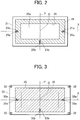
FIG. 2 is an explanatory cross-sectional view at line A-A ofFIG. 1 for showing a positioning mechanism in the fiber reinforced composite member molding apparatus ofFIG. 1 . -
FIG. 3 is an explanatory cross-sectional view at line B-B ofFIG. 1 for showing a positioning mechanism in the fiber reinforced composite member molding apparatus ofFIG. 1 . - With reference to the accompanying drawings, an embodiment of a fiber reinforced composite member molding apparatus according to the present invention will be described below.
-
FIGS. 1 to 3 show an embodiment of the fiber reinforced composite member molding apparatus according to the present invention. - As shown in
FIG. 1 , a molding apparatus 1 is an apparatus to mold a fiber reinforced composite member (thermoplastic CFRP member, for example) from laminated sheets of prepreg formed of woven fiber fabric impregnated with thermosetting or thermoplastic resin, and comprises a pair ofmold parts - Of the two
mold parts lower mold part 2 comprises abase mold 21 fixed on a bolster B and adesign mold 25 detachably attached to thebase mold 21. Thedesign mold 25 has acavity 26. - In the
lower mold part 2, thedesign mold 25 is made of a metal lower in thermal expansion rate than thebase mold 21. Thebase mold 21 is made of, for example tool steel, while thedesign mold 25 is made of an alloy with a low thermal expansion rate, such as inver. - Of the two
mold parts upper mold part 3 comprises abase mold 31 fixed on a slide S which moves up and down, a suspendedbase mold 33 fixed to the slide S by columnar supports 32, and adesign mold 35 detachably attached to the suspendedbase mold 33 to be held between thebase mold 31 and the suspendedbase mold 33. Thedesign mold 35 has acore 36 which, in a mold clamping state, engages with thecavity 26 in thedesign mold 25 of thelower mold part 2 so that the laminated sheets of prepreg, referred to as layered prepreg P (material to be molded into a fiber reinforced composite member), are clamped between thecore 36 and thecavity 26 in thedesign mold 25. - Also in the
upper mold part 3, thedesign mold 35 is made of a metal lower in thermal expansion rate than the suspendedbase mold 33. The suspendedbase mold 33 is made of, for example tool steel, while the design mold 2535 is made of an alloy with a low thermal expansion rate, such as inver. - The molding apparatus 1 has heat sources (heating system) 4, 4 to apply heat to the
design molds upper mold parts design surface lower mold part 2 and theupper mold part 3 by theheat sources - In the present embodiment, for the
base mold 21 and thedesign mold 25 of thelower mold part 2, a positioning mechanism is provided to place thebase mold 21 and thedesign mold 25 in position with respect to each other. The positioning mechanism is adapted to absorb a difference between the amounts of thermal expansion which thebase mold 21 and the design mold 25 experience when heated by theheat sources - As shown also in
FIG. 2 , the positioning mechanism comprises two second-directionmovement restriction pins movement restriction pin 21b provided to thebase mold 21 of thelower mold part 2. - The two second-direction
movement restriction pins base mold 21, and on the opposite sides of the center C, and thus, near the left and right side faces of the depictedbase mold 21. The first-directionmovement restriction pin 21b is arranged on a second center line Y, which is other of the two center lines X, Y, and in the present embodiment, near the front face of the base mold 21 (near the bottom edge inFIG. 2 ). - The positioning mechanism further comprises two second-direction
movement restriction grooves movement restriction groove 25b formed in thedesign mold 25 of thelower mold part 2. - The two second-direction
movement restriction grooves design mold 25, and extend along the first center line X on the opposite sides of the center C. These two second-directionmovement restriction grooves movement restriction pins base mold 21, thereby restricting movement of thedesign mold 25 relative to thebase mold 21 in the direction of a second center line Y while absorbing a difference between the amounts of thermal expansion in the direction of the first center line X which thebase mold 21 and the design mold 25 experience when heated by theheat sources - The first-direction
movement restriction groove 25b is arranged on a second center line Y, which is other of the two center lines X, Y, and extends along the second center line Y. This first-directionmovement restriction groove 25b is adapted to engage with the first-directionmovement restriction pin 21b of thebase mold 21, thereby restricting movement of thedesign mold 25 relative to thebase mold 21 in the direction of the first center line X while absorbing a difference between the amounts of thermal expansion in the direction of the second center line Y which thebase mold 21 and thedesign mold 25 experience when heated by theheat sources - Incidentally,
FIG. 2 shows thebase mold 21 and thedesign mold 25 which are in position with respect to each other. In this state, the center C and two center lines X, Y of thebase mold 21 are in agreement with those of thedesign mold 25. - To sum up, the positioning mechanism is arranged such that by engaging the two second-direction
movement restriction grooves design mold 25 with the two second-directionmovement restriction pins base mold 21 and engaging the first-directionmovement restriction groove 25b of thedesign mold 25 with the first-directionmovement restriction pin 21b of thebase mold 21, thebase mold 21 and thedesign mold 25 are placed in position with respect to each other, with their centers C, C in agreement. - The positioning mechanism maintains the two
molds base mold 21 and the design mold 25 experience when heated by theheat sources - Also for the suspended
base mold 33 and thedesign mold 35 of theupper mold part 3, the molding apparatus 1 comprises a positioning mechanism to place the twomolds molds heat sources - As shown also in
FIG. 3 , the positioning mechanism comprises two second-direction movement restriction pins 33a, 33a and a first-directionmovement restriction pin 33b provided to the suspendedbase mold 33 of theupper mold part 3. - The two second-direction movement restriction pins 33a, 33a are arranged on a first center line X, which is one of two center lines X, Y crossing at right angles at the center C of the suspended
base mold 33, and on the opposite sides of the center C, and thus, near the left and right side faces of the depicted suspendedbase mold 33. The first-directionmovement restriction pin 33b is arranged on a second center line Y, which is other of the two center lines X, Y, and in the present embodiment, near the front face of the suspended base mold 33 (near the bottom edge inFIG. 3 ). - The positioning mechanism further comprises two second-direction
movement restriction grooves movement restriction groove 35b formed in thedesign mold 35 of theupper mold part 3. - The two second-direction
movement restriction grooves design mold 35, and extend along the first center line X on the opposite sides of the center C. These two second-directionmovement restriction grooves base mold 33, thereby restricting movement of thedesign mold 35 relative to the suspendedbase mold 33 in the direction of a second center line Y while absorbing a difference between the amounts of thermal expansion in the direction of the first center line X which the suspendedbase mold 33 and thedesign mold 35 experience when heated by theheat sources - The first-direction
movement restriction groove 35b is arranged on a second center line Y, which is other of the two center lines X, Y, and extends along the second center line Y. This first-directionmovement restriction groove 35b is adapted to engage with the first-directionmovement restriction pin 33b of the suspendedbase mold 33, thereby restricting movement of thedesign mold 35 relative to the suspendedbase mold 33 in the direction of the first center line X while absorbing a difference between the amounts of thermal expansion in the direction of the second center line Y which the suspendedbase mold 33 and thedesign mold 35 experience when heated by theheat sources - Incidentally, also
FIG. 3 shows the suspendedmold 33 and thedesign mold 35 which are in position with respect to each other. In this state, the center C and two center lines X, Y of the suspendedbase mold 33 are in agreement with those of thedesign mold 35. - To sum up, also this positioning mechanism is arranged such that by engaging the two second-direction
movement restriction grooves design mold 35 with the two second-direction movement restriction pins 33a, 33a of the suspendedbase mold 33 and engaging the first-directionmovement restriction groove 35b of thedesign mold 35 with the first-directionmovement restriction pin 33b of the suspendedbase mold 33, the suspendedbase mold 33 and thedesign mold 35 are placed in position with respect to each other, with their centers C, C in agreement. - Also this positioning mechanism maintains the two
molds base mold 33 and thedesign mold 35 experience when heated by theheat sources - Next, a procedure of how to mold a fiber reinforced composite member with the molding apparatus 1 will be described. First, the
design mold 25 is attached to thebase mold 21 of thelower mold part 2. - Here, by engaging the two second-direction
movement restriction grooves design mold 25 with the two second-direction movement restriction pins 21a, 21a of thebase mold 21 and engaging the first-directionmovement restriction groove 25b of thedesign mold 25 with the first-directionmovement restriction pin 21b of thebase mold 21, thebase mold 21 and thedesign mold 25 are placed in position with respect to each other, with their centers C, C in agreement. The grooves and the pins thus constitute a positioning mechanism. - Next, the
design mold 35 is attached to the suspendedbase mold 33 of theupper mold part 3. - Also here, by engaging the two second-direction
movement restriction grooves design mold 35 with the two second-direction movement restriction pins 33a, 33a of the suspendedbase mold 33 and engaging the first-directionmovement restriction groove 35b of thedesign mold 35 with the first-directionmovement restriction pin 33b of the suspendedbase mold 33, the suspendedbase mold 33 and thedesign mold 35 are placed in position with respect to each other, with their centers C, C in agreement. The grooves and the pins thus constitute a positioning mechanism. - As described above, in the molding apparatus 1, the
mold parts design molds - After preparing the
mold parts cavity 26 in thedesign mold 25 of thelower mold part 2. - Then, the
upper mold part 3 is moved down with the slide S, thereby bringing the two mold parts into a mold clamping state. Consequently, the layered prepreg P is clamped between the core 36 of thedesign mold 35 of theupper mold part 3 and thecavity 26 in thedesign mold 25 of thelower mold part 2. In this state, heat is applied to the layered prepreg P by theheat sources design molds upper mold part 3 and thelower mold part 2. - During this process, the positioning mechanism provided for the
base mold 21 and thedesign mold 25 of thelower mold part 2 absorbs a difference between the amounts of thermal expansion in the direction of the first center line X and in the direction of the second center line Y which thebase mold 21 and thedesign mold 25 experience by being heated by theheat sources molds - Likewise, the positioning mechanism provided for the suspended
base mold 33 and thedesign mold 35 of theupper mold part 3 absorbs a difference between the amounts of thermal expansion in the direction of the first center line X and in the direction of the second center line Y which the suspendedbase mold 33 and thedesign mold 35 experience by being heated by theheat sources molds - When the resin is a thermosetting resin, the thermosetting resin is cured by causing the
heat sources 4 to continue the heating operation, and then, supply of electricity to theheat sources 4 is stopped. Consequently, a product (fiber reinforced composite member) molded from the layered prepreg P is obtained. - When the resin is a thermoplastic resin, after the application of pressure, supply of electricity to the
heat sources 4 is stopped to cool and thereby cure the thermoplastic resin through theupper mold part 3 and thelower mold part 2. Consequently, a product (fiber reinforced composite member) molded from the layered prepreg P is obtained. - In this molding apparatus 1, the
design molds mold parts base mold 21 and the suspendedbase mold 33. During heating for molding, this can suppress the influence of thermal expansion of thedesign molds mold parts - In the described embodiment, the positioning mechanism for the lower mold part comprises two second-direction movement restriction pins 21a, 21a and a first-direction
movement restriction pin 21b provided to thebase mold 21 of thelower mold part 2, and two second-directionmovement restriction grooves movement restriction groove 25b formed in thedesign mold 25 of the lower mold part 5. The positioning mechanism is however not restricted to this; it may be altered to comprise two second-direction movement restriction pins and a first-direction movement restriction pin provided to thedesign mold 25 of thelower mold part 2, and two second-direction movement restriction grooves and a first-direction movement restriction groove formed in thebase mold 21 of thelower mold part 2. - Likewise, the positioning mechanism for the upper mold part may be altered to comprise two second-direction movement restriction pins and a first-direction movement restriction pin provided to the
design mold 35 of theupper mold part 3, and two second-direction movement restriction grooves and a first-direction movement restriction groove formed in the suspendedbase mold 33 of theupper mold part 3. - Further, the embodiment has been described based on an example in which the woven carbon-fiber fabric constituting the prepreg is woven carbon-fiber fabric, or fabric woven from carbon fibers. The present invention is however not restricted to this.
- The fiber reinforced composite member molding apparatus according to the present disclosure is not restricted to the described embodiment.
- A first aspect of the present invention comprises a pair of mold parts which are brought nearer to and away from each other, and in a mold clamping state, clamps laminated sheets of prepreg formed of woven fiber fabric impregnated with resin (thermosetting or thermoplastic resin), and a heating system for heating the resin in the prepreg through the pair of mold parts, wherein the two mold parts each comprise a base mold and a design mold which is detachably attached to the base mold and brought into contact with the prepreg, wherein the design molds of the mold parts are made of a metal lower in thermal expansion rate than the base molds.
- In the fiber reinforced composite member molding apparatus according to the first aspect of the present invention, the two mold parts each have a split structure, and thus, when replacement of the mold parts is required, the replacement can be accomplished by replacing only the design molds. This reduces the burden on operators handling the replacement.
- In addition, in the fiber reinforced composite member molding apparatus according to the first aspect of the present invention, the design molds of the mold parts are made of a metal lower in thermal expansion rate than the base molds. During heating for molding, this can suppress the influence of thermal expansion of the design molds of the mold parts upon a to-be-molded fiber reinforced composite member.
- In a second aspect of the present invention, for the base mold and the design mold of each of the two mold parts, a positioning mechanism is provided to place the base mold and the design mold in position with respect to each other, the positioning mechanism being adapted to absorb a difference between the amounts of thermal expansion which the base mold and the design mold experience by being heated by the heating system.
- Consequently, the positioning mechanism can maintain the base mold and the design mold in position with respect to each other.
- In a third aspect of the present disclosure, the positioning mechanism comprises two second-direction movement restriction pins provided on the first of two center lines crossing at right angles at a center of one of the two molds: the base mold and the design mold, the two second-direction movement restriction pins being arranged on opposite sides of the center; a first-direction movement restriction pin provided on the second of the two center lines; two second-direction movement restriction grooves provided on and extending along the first of two center lines crossing at right angles at a center of the other of the two molds, the two second-direction movement restriction grooves being arranged on opposite sides of the center and adapted to engage with the two second-direction movement restriction pins; and a first-direction movement restriction groove provided on and extending along the second of the two center lines and adapted to engage with the first-direction movement restriction pin.
- In the fiber reinforced composite member molding apparatus according to the third aspect of the present invention, the base mold and the design mold are placed in position with respect to each other, with their centers in agreement.
- In the fiber reinforced composite member molding apparatus according to each aspect of the present invention, the base mold of each mold part is made of, for example tool steel, while the design mold is made of an alloy with a low thermal expansion rate, such as inver (registered trademark).
- In the fiber reinforced composite member molding apparatus according to each aspect of the present invention, the woven fiber fabric constituting the prepreg may be woven carbon-fiber fabric, or fabric woven from carbon fibers. The present invention is however not restricted to this.
- Here, resins usable as a matrix with which to impregnate the woven fiber fabric include thermosetting resins such as epoxy resin, phenol resin and polyimide resin, and thermoplastic resins such as PEEK (polyether ether ketone resin), PEI (polyetherimide resin) and PIXA (thermoplastic polyimide resin).
-
- 1 Fiber reinforced composite member molding apparatus
- 2 Lower mold part (pair of mold parts)
- 3 Upper mold (pair of mold parts)
- 4 Heat source (heating system)
- 21, 31 Base mold
- 21a, 33a Second-direction movement restriction pin (positioning mechanism)
- 21b, 33b First-direction movement restriction pin (positioning mechanism)
- 25, 35 Design mold
- 25a, 35a Second-direction movement restriction groove (positioning mechanism)
- 25b, 35b First-direction movement restriction groove (positioning mechanism)
- 33 Suspended base mold
- C Center of mold
- P Layered prepreg (material to be molded into a fiber reinforced composite member)
- X Center line
- Y Center line
Claims (3)
- A fiber reinforced composite member molding apparatus, comprising
a pair of mold parts which are brought nearer to and away from each other, and in a mold clamping state, clamps laminated sheets of prepreg formed of woven fiber fabric impregnated with resin, and
a heating system for heating the resin in the prepreg through the pair of mold parts, wherein
the two mold parts each comprise a base mold and a design mold which is detachably attached to the base mold and brought into contact with the prepreg, wherein
the design molds of the mold parts are made of a metal lower in thermal expansion rate than the base molds. - The fiber-reinforced composite member molding apparatus according to claim 1, wherein for the base mold and the design mold of each of the two mold parts, a positioning mechanism is provided to place the base mold and the design mold in position with respect to each other, the positioning mechanism being adapted to absorb a difference between the amounts of thermal expansion which the base mold and the design mold experience by being heated by the heating system.
- The fiber-reinforced composite member molding apparatus according to claim 2, the positioning mechanism comprises two second-direction movement restriction pins provided on the first of two center lines crossing at right angles at a center of one of the two molds: the base mold and the design mold, the two second-direction movement restriction pins being arranged on opposite sides of the center; a first-direction movement restriction pin provided on the second of the two center lines; two second-direction movement restriction grooves provided on and extending along the first of two center lines crossing at right angles at a center of the other of the two molds, the two second-direction movement restriction grooves being arranged on opposite sides of the center and adapted to engage with the two second-direction movement restriction pins; and a first-direction movement restriction groove provided on and extending along the second of the two center lines and adapted to engage with the first-direction movement restriction pin.
Applications Claiming Priority (1)
| Application Number | Priority Date | Filing Date | Title |
|---|---|---|---|
| PCT/JP2015/078811 WO2017061047A1 (en) | 2015-10-09 | 2015-10-09 | Fiber-reinforced composite member forming device |
Publications (2)
| Publication Number | Publication Date |
|---|---|
| EP3308930A1 true EP3308930A1 (en) | 2018-04-18 |
| EP3308930A4 EP3308930A4 (en) | 2019-02-27 |
Family
ID=57582097
Family Applications (1)
| Application Number | Title | Priority Date | Filing Date |
|---|---|---|---|
| EP15905866.8A Withdrawn EP3308930A4 (en) | 2015-10-09 | 2015-10-09 | DEVICE FOR FORMING A FIBER REINFORCED COMPOSITE ELEMENT |
Country Status (7)
| Country | Link |
|---|---|
| US (1) | US20180104862A1 (en) |
| EP (1) | EP3308930A4 (en) |
| JP (1) | JP6052526B1 (en) |
| CN (1) | CN107683194B (en) |
| CA (1) | CA2992083C (en) |
| RU (1) | RU2690804C1 (en) |
| WO (1) | WO2017061047A1 (en) |
Cited By (1)
| Publication number | Priority date | Publication date | Assignee | Title |
|---|---|---|---|---|
| US20220402828A1 (en) * | 2021-06-18 | 2022-12-22 | Goodrich Corporation | Shape forming opf preform |
Families Citing this family (3)
| Publication number | Priority date | Publication date | Assignee | Title |
|---|---|---|---|---|
| CN108466435B (en) * | 2018-02-14 | 2020-04-28 | 北京航空航天大学 | Design of a composite material wing anti-curing deformation mold |
| DE102021000923A1 (en) * | 2021-02-22 | 2022-08-25 | Siempelkamp Maschinen- Und Anlagenbau Gmbh | Press system and press tool for a press system, and method for manufacturing a workpiece |
| JP7683573B2 (en) * | 2022-09-16 | 2025-05-27 | トヨタ自動車株式会社 | High pressure tank mold structure |
Family Cites Families (18)
| Publication number | Priority date | Publication date | Assignee | Title |
|---|---|---|---|---|
| JPH085080B2 (en) * | 1987-04-27 | 1996-01-24 | 三井東圧化学株式会社 | Method for producing fiber-reinforced thermoplastics |
| JPH04239612A (en) * | 1991-01-24 | 1992-08-27 | Sekisui Chem Co Ltd | Mold for thermocompression molding |
| US5897814A (en) * | 1997-06-13 | 1999-04-27 | General Electric Company | Method for injection molding of optical discs |
| JP3490606B2 (en) * | 1998-03-20 | 2004-01-26 | 富士通株式会社 | Mold for semiconductor device manufacturing |
| AU2003210593A1 (en) * | 2002-01-22 | 2003-09-02 | E.I. Du Pont De Nemours And Company | Compression mould for making a membrane electrode assembly |
| US20040096535A1 (en) * | 2002-11-15 | 2004-05-20 | Hudecek Robert W. | Compression molding apparatus having replaceable mold inserts |
| JP4202844B2 (en) * | 2003-07-02 | 2008-12-24 | 川崎重工業株式会社 | Composite material forming jig |
| JP2006130675A (en) * | 2004-11-02 | 2006-05-25 | Fj Composite:Kk | CFRP mold, CFRP molded body, and method for producing CFRP molded body |
| EP1880828A1 (en) * | 2005-05-10 | 2008-01-23 | Dainippon Ink and Chemicals, Incorporated | Process for forming thermoformable sheet and forming machine |
| DE102005053690A1 (en) * | 2005-11-10 | 2007-05-31 | Airbus Deutschland Gmbh | Tool, assembly and method for manufacturing a component, component |
| GB0813785D0 (en) * | 2008-07-29 | 2008-09-03 | Airbus Uk Ltd | Method of manufacturing a composite element |
| DE102009052213A1 (en) * | 2009-11-06 | 2011-05-12 | Meissner Formentechnologie Gmbh | Heatable tool for producing molded parts, comprises base support made from metal, a molded bed made from plastic, and a connecting layer made from heat-conductive plastic and present between the base support and the molded bed |
| GB0913847D0 (en) * | 2009-08-07 | 2009-09-16 | Surface Generation Ltd | Composite tool pin |
| DE202010002328U1 (en) * | 2010-02-12 | 2010-10-14 | Konstruktionsbüro Hein GmbH | mold |
| FR2959694B1 (en) * | 2010-05-10 | 2012-08-03 | Lorraine Construction Aeronautique | DEVICE FOR MANUFACTURING A COMPOSITE PIECE BY RESIN INJECTION |
| JP5794496B2 (en) * | 2012-04-24 | 2015-10-14 | 株式会社ナカトガワ技研 | Mold positioning mechanism |
| JP2014205317A (en) * | 2013-04-15 | 2014-10-30 | 株式会社イケックス工業 | Resin molding die and manufacturing method thereof |
| JP6104730B2 (en) * | 2013-06-18 | 2017-03-29 | 三菱重工業株式会社 | Mold and molding method of composite material |
-
2015
- 2015-10-09 EP EP15905866.8A patent/EP3308930A4/en not_active Withdrawn
- 2015-10-09 CN CN201580081015.8A patent/CN107683194B/en not_active Expired - Fee Related
- 2015-10-09 JP JP2015551898A patent/JP6052526B1/en active Active
- 2015-10-09 RU RU2018116978A patent/RU2690804C1/en active
- 2015-10-09 CA CA2992083A patent/CA2992083C/en active Active
- 2015-10-09 WO PCT/JP2015/078811 patent/WO2017061047A1/en not_active Ceased
-
2017
- 2017-12-18 US US15/844,783 patent/US20180104862A1/en not_active Abandoned
Cited By (1)
| Publication number | Priority date | Publication date | Assignee | Title |
|---|---|---|---|---|
| US20220402828A1 (en) * | 2021-06-18 | 2022-12-22 | Goodrich Corporation | Shape forming opf preform |
Also Published As
| Publication number | Publication date |
|---|---|
| CN107683194A (en) | 2018-02-09 |
| JPWO2017061047A1 (en) | 2017-10-05 |
| CA2992083A1 (en) | 2017-04-13 |
| CA2992083C (en) | 2019-08-20 |
| US20180104862A1 (en) | 2018-04-19 |
| EP3308930A4 (en) | 2019-02-27 |
| CN107683194B (en) | 2019-11-12 |
| RU2690804C1 (en) | 2019-06-05 |
| JP6052526B1 (en) | 2016-12-27 |
| WO2017061047A1 (en) | 2017-04-13 |
Similar Documents
| Publication | Publication Date | Title |
|---|---|---|
| US20180104862A1 (en) | Fiber reinforced composite member molding apparatus | |
| US11052574B2 (en) | Fiber reinforced composite member molding apparatus | |
| US12330381B2 (en) | Preform shaping apparatus, preform shaping method and composite material molding method | |
| US20160354967A1 (en) | Method for producing resin molded body and press molding apparatus | |
| US11826976B2 (en) | FRP molding system and method | |
| EP3024627B1 (en) | Mould arrangement and method for compression moulding fiber reinforced preforms | |
| EP3498465A1 (en) | Induction heating cell with cauls over mandrels and method of using it | |
| US8649897B2 (en) | Laying-up method for non-planar composite components | |
| US11292160B2 (en) | Bladder that changes stiffness based on temperature effects for manufacture of composite components | |
| US10639840B2 (en) | Device and method for forming a composite panel from a thermoplastic matrix | |
| JP2015160371A (en) | System and method for controlling resin flow | |
| JP6697819B2 (en) | Composite material forming apparatus and composite material forming method | |
| US20170043540A1 (en) | Multi-State Bladder for Manufacture of Composite Material | |
| EP3300872A1 (en) | Fiber-reinforced composite member molding device | |
| US12415324B2 (en) | Method for manufacturing moulded parts from fibre composite material | |
| US20210291467A1 (en) | Composite Charge Positioning System | |
| EP3572201A1 (en) | Method for manufacturing fiber-reinforced plastic | |
| JP4202844B2 (en) | Composite material forming jig | |
| WO2012157327A1 (en) | Resin transfer molding method and resin transfer molding device | |
| EP2679365A1 (en) | Method for manufacturing preform | |
| US10647070B2 (en) | Object production | |
| KR20180009962A (en) | Molding apparatus for fiber-reinforced resin molded product | |
| JP2016165856A (en) | Fiber reinforced plastic manufacturing apparatus and manufacturing method | |
| JP2008246814A (en) | FRP long pipe-shaped molding method and mold used therefor | |
| JP2010023364A (en) | Method of manufacturing hollow product using fiber-reinforced material and manufacturing device |
Legal Events
| Date | Code | Title | Description |
|---|---|---|---|
| STAA | Information on the status of an ep patent application or granted ep patent |
Free format text: STATUS: THE INTERNATIONAL PUBLICATION HAS BEEN MADE |
|
| PUAI | Public reference made under article 153(3) epc to a published international application that has entered the european phase |
Free format text: ORIGINAL CODE: 0009012 |
|
| STAA | Information on the status of an ep patent application or granted ep patent |
Free format text: STATUS: REQUEST FOR EXAMINATION WAS MADE |
|
| 17P | Request for examination filed |
Effective date: 20180109 |
|
| AK | Designated contracting states |
Kind code of ref document: A1 Designated state(s): AL AT BE BG CH CY CZ DE DK EE ES FI FR GB GR HR HU IE IS IT LI LT LU LV MC MK MT NL NO PL PT RO RS SE SI SK SM TR |
|
| AX | Request for extension of the european patent |
Extension state: BA ME |
|
| DAV | Request for validation of the european patent (deleted) | ||
| DAX | Request for extension of the european patent (deleted) | ||
| A4 | Supplementary search report drawn up and despatched |
Effective date: 20190129 |
|
| RIC1 | Information provided on ipc code assigned before grant |
Ipc: B29C 43/36 20060101AFI20190123BHEP Ipc: B29C 33/02 20060101ALN20190123BHEP Ipc: B29C 33/38 20060101ALI20190123BHEP Ipc: B29C 43/52 20060101ALI20190123BHEP Ipc: B29C 70/46 20060101ALI20190123BHEP |
|
| STAA | Information on the status of an ep patent application or granted ep patent |
Free format text: STATUS: EXAMINATION IS IN PROGRESS |
|
| 17Q | First examination report despatched |
Effective date: 20200221 |
|
| STAA | Information on the status of an ep patent application or granted ep patent |
Free format text: STATUS: THE APPLICATION IS DEEMED TO BE WITHDRAWN |
|
| 18D | Application deemed to be withdrawn |
Effective date: 20210310 |