EP3308872A1 - Seaming device - Google Patents
Seaming device Download PDFInfo
- Publication number
- EP3308872A1 EP3308872A1 EP16807356.7A EP16807356A EP3308872A1 EP 3308872 A1 EP3308872 A1 EP 3308872A1 EP 16807356 A EP16807356 A EP 16807356A EP 3308872 A1 EP3308872 A1 EP 3308872A1
- Authority
- EP
- European Patent Office
- Prior art keywords
- seaming
- lid
- unit
- chuck
- turret
- Prior art date
- Legal status (The legal status is an assumption and is not a legal conclusion. Google has not performed a legal analysis and makes no representation as to the accuracy of the status listed.)
- Withdrawn
Links
Images



Classifications
-
- B—PERFORMING OPERATIONS; TRANSPORTING
- B21—MECHANICAL METAL-WORKING WITHOUT ESSENTIALLY REMOVING MATERIAL; PUNCHING METAL
- B21D—WORKING OR PROCESSING OF SHEET METAL OR METAL TUBES, RODS OR PROFILES WITHOUT ESSENTIALLY REMOVING MATERIAL; PUNCHING METAL
- B21D51/00—Making hollow objects
- B21D51/16—Making hollow objects characterised by the use of the objects
- B21D51/26—Making hollow objects characterised by the use of the objects cans or tins; Closing same in a permanent manner
- B21D51/30—Folding the circumferential seam
- B21D51/32—Folding the circumferential seam by rolling
-
- B—PERFORMING OPERATIONS; TRANSPORTING
- B21—MECHANICAL METAL-WORKING WITHOUT ESSENTIALLY REMOVING MATERIAL; PUNCHING METAL
- B21D—WORKING OR PROCESSING OF SHEET METAL OR METAL TUBES, RODS OR PROFILES WITHOUT ESSENTIALLY REMOVING MATERIAL; PUNCHING METAL
- B21D39/00—Application of procedures in order to connect objects or parts, e.g. coating with sheet metal otherwise than by plating; Tube expanders
- B21D39/02—Application of procedures in order to connect objects or parts, e.g. coating with sheet metal otherwise than by plating; Tube expanders of sheet metal by folding, e.g. connecting edges of a sheet to form a cylinder
-
- B—PERFORMING OPERATIONS; TRANSPORTING
- B21—MECHANICAL METAL-WORKING WITHOUT ESSENTIALLY REMOVING MATERIAL; PUNCHING METAL
- B21D—WORKING OR PROCESSING OF SHEET METAL OR METAL TUBES, RODS OR PROFILES WITHOUT ESSENTIALLY REMOVING MATERIAL; PUNCHING METAL
- B21D51/00—Making hollow objects
- B21D51/16—Making hollow objects characterised by the use of the objects
- B21D51/26—Making hollow objects characterised by the use of the objects cans or tins; Closing same in a permanent manner
-
- B—PERFORMING OPERATIONS; TRANSPORTING
- B21—MECHANICAL METAL-WORKING WITHOUT ESSENTIALLY REMOVING MATERIAL; PUNCHING METAL
- B21D—WORKING OR PROCESSING OF SHEET METAL OR METAL TUBES, RODS OR PROFILES WITHOUT ESSENTIALLY REMOVING MATERIAL; PUNCHING METAL
- B21D51/00—Making hollow objects
- B21D51/16—Making hollow objects characterised by the use of the objects
- B21D51/26—Making hollow objects characterised by the use of the objects cans or tins; Closing same in a permanent manner
- B21D51/2653—Methods or machines for closing cans by applying caps or bottoms
-
- B—PERFORMING OPERATIONS; TRANSPORTING
- B21—MECHANICAL METAL-WORKING WITHOUT ESSENTIALLY REMOVING MATERIAL; PUNCHING METAL
- B21D—WORKING OR PROCESSING OF SHEET METAL OR METAL TUBES, RODS OR PROFILES WITHOUT ESSENTIALLY REMOVING MATERIAL; PUNCHING METAL
- B21D51/00—Making hollow objects
- B21D51/16—Making hollow objects characterised by the use of the objects
- B21D51/26—Making hollow objects characterised by the use of the objects cans or tins; Closing same in a permanent manner
- B21D51/2653—Methods or machines for closing cans by applying caps or bottoms
- B21D51/2661—Sealing or closing means therefor
-
- B—PERFORMING OPERATIONS; TRANSPORTING
- B21—MECHANICAL METAL-WORKING WITHOUT ESSENTIALLY REMOVING MATERIAL; PUNCHING METAL
- B21D—WORKING OR PROCESSING OF SHEET METAL OR METAL TUBES, RODS OR PROFILES WITHOUT ESSENTIALLY REMOVING MATERIAL; PUNCHING METAL
- B21D51/00—Making hollow objects
- B21D51/16—Making hollow objects characterised by the use of the objects
- B21D51/26—Making hollow objects characterised by the use of the objects cans or tins; Closing same in a permanent manner
- B21D51/2692—Manipulating, e.g. feeding and positioning devices; Control systems
-
- B—PERFORMING OPERATIONS; TRANSPORTING
- B21—MECHANICAL METAL-WORKING WITHOUT ESSENTIALLY REMOVING MATERIAL; PUNCHING METAL
- B21D—WORKING OR PROCESSING OF SHEET METAL OR METAL TUBES, RODS OR PROFILES WITHOUT ESSENTIALLY REMOVING MATERIAL; PUNCHING METAL
- B21D51/00—Making hollow objects
- B21D51/16—Making hollow objects characterised by the use of the objects
- B21D51/26—Making hollow objects characterised by the use of the objects cans or tins; Closing same in a permanent manner
- B21D51/30—Folding the circumferential seam
-
- B—PERFORMING OPERATIONS; TRANSPORTING
- B21—MECHANICAL METAL-WORKING WITHOUT ESSENTIALLY REMOVING MATERIAL; PUNCHING METAL
- B21D—WORKING OR PROCESSING OF SHEET METAL OR METAL TUBES, RODS OR PROFILES WITHOUT ESSENTIALLY REMOVING MATERIAL; PUNCHING METAL
- B21D51/00—Making hollow objects
- B21D51/16—Making hollow objects characterised by the use of the objects
- B21D51/38—Making inlet or outlet arrangements of cans, tins, baths, bottles, or other vessels; Making can ends; Making closures
- B21D51/44—Making closures, e.g. caps
- B21D51/446—Feeding or removal of material
-
- B—PERFORMING OPERATIONS; TRANSPORTING
- B21—MECHANICAL METAL-WORKING WITHOUT ESSENTIALLY REMOVING MATERIAL; PUNCHING METAL
- B21D—WORKING OR PROCESSING OF SHEET METAL OR METAL TUBES, RODS OR PROFILES WITHOUT ESSENTIALLY REMOVING MATERIAL; PUNCHING METAL
- B21D37/00—Tools as parts of machines covered by this subclass
- B21D37/18—Lubricating, e.g. lubricating tool and workpiece simultaneously
Definitions
- the present invention relates to a seaming device equipped with a can placement unit that places a can, a chuck unit provided opposite the can placement unit, and a seaming roll that seams a lid to the can.
- a known seaming device for example as shown in Patent Literature 1, includes a seaming turret (1) that performs the process of seaming cans and lids, an infeed conveyor (supply conveyor 7) that supplies cans prior to seaming to the seaming turret, a lid transfer turret (supply turret 3) of a lid supply unit that supplies lids, a discharge turret (discharge turret 5) that carries the seamed cans out of the seaming turret, and an outfeed conveyor (discharge conveyor 8) that carries the cans out of the discharge turret further to the outside.
- the seaming turret, discharge turret, and lid transfer turret are each provided with pockets (fitting recesses 2, 4, and 6) in their outer peripheral parts for individually accommodating and transferring cans and lids.
- Each pocket of the seaming turret is provided with a can placement unit (lifter 17) where cans are placed, a chuck unit (seaming chuck device 10) provided opposite the can placement unit, and a seaming roll (18, 19) that seams lids to cans.
- Such a seaming device configured as described above is capable of continuous seaming of cans and lids as they are transferred from one place to another at high speed, with the respective turrets and conveyors operating at speeds and timings matched by means of gears or the like, and by the actions of the can placement unit, chuck unit, and seaming unit disposed in each pocket coordinated with the rotation of the seaming turret by means of gears, cam mechanisms and the like.
- Patent Literature 1 Japanese Patent Application Laid-open No. S62-244537
- the can placement unit (lifter) provided to each pocket of the seaming turret, and knockout pads, if any, are each lifted and lowered by a cam mechanism in coordination with the rotation of the seaming turret.
- the can placement unit (lifter) is lifted up to hold the can and lid between the lifter and the chuck to seam the lid on the can.
- the transfer of the can supplied from the infeed conveyor to the can placement unit (lifter) of the seaming turret for the seaming operation makes the posture of the can unstable.
- the can may hit a guide or a pocket of the seaming turret and dents may be created, which can result in buckling during the seaming.
- High-speed lifting of the can by the can placement unit makes its posture unstable and decenters the can, which similarly causes the can to hit a guide or a pocket of the seaming turret and dents to be created.
- the present invention solves the problems described above, its object being to provide a seaming device capable of preventing dents caused by a can guide or a seaming turret pocket, and buckling resulting from the dents during seaming, and capable of improving seaming accuracy, by stabilizing the posture of the can being transferred when the can is supplied from an infeed conveyor.
- the seaming device is a seaming device including a can placement unit that places a can, a chuck unit that is provided opposite the can placement unit, and a seaming unit that seams a lid to the can, the can placement unit including a pressing mechanism that presses a plate, on which the can is placed, resiliently upward, and the chuck unit and the seaming unit being configured to be capable of moving up and down, whereby the above problems are solved.
- the can placement unit includes the pressing mechanism that presses the plate on which the can is placed resiliently upward, and the chuck unit and seaming unit are configured capable of moving up and down, so that the can placement unit need not be lifted or lowered in a state wherein the plate of the can placement unit is rotating.
- the can does not move up and down and stays stable when it is transferred from the infeed conveyor to the can placement unit. Therefore, dents caused by guides or pockets of the seaming turret, and buckling during seaming resulting from such dents are prevented, and the seaming accuracy can be improved.
- the chuck unit and seaming unit are formed integrally so as to be moved up and down by a single cam mechanism. This can prevent changes in the positions of the chuck and seaming roll resulting from expansion caused by friction heat generated between a rotary shaft and an oil seal and the like, so that maintenance is made easy.
- rotation of the plate of the can placement unit and rotation of the chuck of the chuck unit, and the seaming operation by the seaming roll of the seaming unit are achieved by driving sources that are independently controlled.
- the timing of starting or accelerating the rotation of the plate and chuck, and the timing of the seaming operation can be adjusted individually and optimally without stopping the operation by separate control of respective driving sources, so that the adjustment operation can be performed easily in a short time.
- the seaming device includes an infeed conveyor that supplies cans to the seaming turret, and a lid supply unit made up of a lid feeder that feeds lids and a lid transfer turret.
- the infeed conveyor, lid feeder, and lid transfer turret each have an independently controlled driving source, the operation timing can be adjusted individually and optimally in accordance with the size or weight of the can, seam size, etc., without stopping the operation, and the adjustment operation can be performed easily in a short time.
- the driving sources are servomotors, so that adjustments can be made by electrical control commands, and feedback control is also possible.
- the adjustment operation can be performed more easily in a short time.
- cans on which lids have been placed are supplied to the seaming turret by the infeed conveyor, so that seaming is performed by the chuck unit and seaming unit without the need to lift and lower the plate of the can placement unit.
- the chuck unit causes the chuck alone to make contact with the lid, and lowers the chuck for centering the lid and for pressing the lid, so that it is easier to correct the position of the lid. No eccentric load is applied so that buckling of the can is prevented, which enables a further reduction in the can thickness.
- the chuck includes lid suction means. Since the chuck holds the lid by suction and increases the fitting force, seaming failures resulting from slippage are prevented. This enables a reduction in axial load applied to the can, so that buckling of the can is prevented, and can thickness can be reduced.
- the chuck holds the lid by suction with its lid suction means to achieve centering of the lid, and is lowered to place the lid on the can thereafter so that the seaming is performed by the chuck unit and seaming unit without the need to lift and lower the plate of the can placement unit.
- the seaming turret includes detection means that detects the positions of the pockets.
- a pitch sensor that detects attachments of the infeed conveyor is provided on the transfer path of the infeed conveyor, so that the adjustment operation can be performed more easily. Also, automatic detection and correction of position errors, or position variations during operation, of each pocket or attachment, are made possible, so that the seaming accuracy can be improved and the speed of seaming operation can be increased.
- the chuck unit includes a rotary vane pump that forcibly discharges lubricating oil, so that the amount of lubricating oil stored above the oil seal can be made minimum. Lubricating oil leakage from the oil seal or stain that may occur as the chuck rotates can be prevented.
- the pressing mechanism of the can placement unit is configured to operate by fluid pressure, so that a constant pressing force can be achieved and the adjustment is made very easy.
- the seaming accuracy can thus be improved and the speed of seaming operation can be increased.
- a diaphragm for sealing the fluid pressure is included, so that a sealing member that operates in sliding contact is made unnecessary.
- the plate can be lifted and lowered smoothly, as there is no seal resistance in the vertical movement.
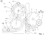
- the seaming device 100 includes, as shown in Fig. 1 , a seaming turret 101 that performs the process of seaming cans C and lids F, an infeed conveyor 102 that supplies cans C on which lids F have been placed to the seaming turret 101, a lid feeding unit 104 composed of a lid feeder 105 that supplies lids F and a lid transfer turret 106, a discharge turret 107 that carries the seamed cans CM out of the seaming turret 101, and an outfeed conveyor 108 that carries the cans CM out of the discharge turret 107 further to the outside.
- Cans C on which lids F have been placed are supplied to the seaming turret 101 by the infeed conveyor 102, so that seaming is performed by a chuck unit 120 and a seaming unit 130 without the necessity to lift and lower the plate 112 of the can placement unit 110 to be described later.
- the seaming turret 101, discharge turret 107, and lid transfer turret 106 are each provided with pockets P in their outer peripheral parts for individually accommodating and transferring the cans C or CM and lids F.
- the infeed conveyor 102 is provided with attachments 103 that individually engage with and transfer cans C.
- the rotation speeds of the seaming turret 101, discharge turret 107, and lid transfer turret 106, the moving speed of the attachments 103 of the infeed conveyor 102, and coordinated timing of each pocket P and attachment 103 are designed adjustable so that the cans C or CM and lids F are smoothly transferred between respective turrets and conveyors.
- the seaming turret 101 that performs the process of seaming cans C and lids F includes, as shown in Fig. 3 , a can placement unit 110 where cans C are placed, a chuck unit 120 provided opposite the can placement unit 110, and a seaming unit 130 having a seaming roll 131 that seams the lid F to the can C, in each of the pockets P.
- the seaming turret 101 is configured to be rotated by a drive motor 151 of the seaming turret, and the pocket positions can be detected by a pocket position detection encoder 155 from the rotation phases.
- a pitch sensor S made up of a phototube, proximity switch, laser and the like is provided on a transfer path of the infeed conveyor 102 for detecting the positions of the attachments 103 of the infeed conveyor 102.
- the positions of the attachments 103 relative to the pockets P of the seaming turret 101 and lid transfer turret 106 are controlled based on the outputs of this pitch sensor S.
- Such detection and control can further facilitate adjustment operations, as well as enable automatic detection and correction of position errors, or position variations during operation, of each pocket P or attachment 103, so that the seaming accuracy can be improved and the speed of seaming operation can be increased.
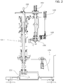
- the lid feeder 105, lid transfer turret 106, and infeed conveyor 102 are driven by a drive motor 153 of the lid feeder 105, a drive motor 152 of the lid transfer turret 106, and a drive motor 154 of the infeed conveyor 102, respectively, as shown in Fig. 2 .
- Servomotors are adopted as these motors, which are configured such that the speed and timing are individually adjustable, and that they are capable of following speed and timing fluctuations of the seaming turret 101, in accordance with the outputs of the pocket position detection encoder 155.
- the operation timing can be adjusted individually and optimally in accordance with the size or weight of the can, seam size, etc., without stopping the operation, and the adjustment operation can be performed easily in a short time.
- the driving sources are servomotors, adjustments can be made by electrical control commands, and feedback control is also possible. Thus the adjustment operation can be performed more easily in a short time.
- any suitable driving sources may be used, as represented by drive force transmitted mechanically via a transmission mechanism from the drive motor 151 of the seaming turret 101.
- Any suitable driving sources as represented by drive force transmitted mechanically via a transmission mechanism from the drive motor 151 of the seaming turret 101, may be used also for the lid feeder 105, lid transfer turret 106, and infeed conveyor 102, as long as they are designed such that the speed and timing are easily adjustable in terms of accuracy and speed.
- the can placement unit 110 includes a plate 112 on which a can C is placed, and a pressing mechanism 111 that presses the plate 112 resiliently upward with a spring, compressed air, and the like.
- the can placement unit 110 is configured not to move up and down except for the plate 112 being moved up and down by the pressing mechanism 111.
- the chuck unit 120 moves up and down by means of a vertical motion mechanism 122 of the chuck unit 120 made up of a vertical motion cam 123 and a vertical motion cam follower 124 as shown in Fig. 3 .
- the vertical motion cam 123 of the chuck unit 120 is fixedly provided, so that, as the seaming turret 101 rotates, the vertical motion cam follower 124 of the chuck unit 120 moves in conformity to the cam profile to cause the chuck 121 in the chuck unit 120 to move up and down at corresponding positions.
- the width (thickness) of a gear each attached to the chuck unit 120 and the drive motor 156 of the chuck 121 to be described later is set suitably to control the rotation of the chuck 121 by the drive motor 156 in the up and down movement of the chuck unit 120.
- This control of rotation can be achieved by adopting or adding suitable means.
- the seaming roll 131 of the seaming unit 130 similarly moves up and down by means of a vertical motion mechanism 133 of the seaming unit 130 made up of a vertical motion cam 134 and a vertical motion cam follower 135 as shown in Fig. 3 .
- the vertical motion cam 134 of the seaming unit 130 is fixedly provided, so that, as the seaming turret 101 rotates, the vertical motion cam follower 135 of the seaming unit 130 moves in conformity to the cam profile to cause the seaming unit 130 to move up and down at corresponding positions.
- the seaming unit 130 includes a spline K above a roll pivot shaft 132 to enable extension/contraction and rotation of the roll pivot shaft 132.
- the seaming roll 131 is moved up and down by the vertical motion mechanism 133 mentioned above, as well as the seaming operation and pressing by the seaming roll 131 are achieved by the drive motor 158 of the roll pivot shaft 132 to be described later.
- Means for enabling vertical motion, seaming operation, and pressing of the seaming roll 131 are not necessarily limited to the spline K or the like of the roll pivot shaft 132, and any suitable means may be adopted or added.
- the can placement unit 110 includes the pressing mechanism 111 that presses the plate 112 on which the can is placed resiliently upward, and since the chuck unit 120 and seaming unit 130 can move up and down, the can placement unit 110 need not be lifted or lowered in a state wherein the plate 112 is rotating.
- the can C does not move up and down and stays stable when it is transferred from the infeed conveyor 102 to the can placement unit 110. Therefore, dents caused by guides or pockets P of the seaming turret 101, and buckling during seaming resulting from such dents are prevented, and the seaming accuracy can be improved.
- the driving sources for the rotation of the plate 112 of the can placement unit 110 and the chuck 121 of the chuck unit 120 are the drive motor 157 of the can placement unit 110 and the drive motor 156 of the chuck 121, respectively, which are independently controlled servomotors, as shown in Fig. 3 .
- Such driving allows independent control of the timing of starting or accelerating rotation of the plate 112 and chuck 121 for individual optimal adjustment without stopping the operation by an operation panel or the like, so that the adjustment operation can be performed easily in a short time, and fluctuations can be dealt with during the operation.
- the rotation of the plate 112 and chuck 121 can be stopped or slowed down when fitting the rotating chuck 121 with the lid placed on the can, to reduce misalignment between the rotation centers, whereby dents, scratches, or the like on the can caused by contact with guide members or the like are prevented, and also, the lid centering performance of the chuck 121 can be improved.
- the driving source of the roll pivot shaft 132 of the seaming unit 130 is the drive motor 158 of the roll pivot shaft 132 which is an independently controlled servomotor.
- the timing of the seaming operation or amount of pressure applied by the seaming roll 131 can be independently controlled and individually optimally adjusted without stopping the operation by an operation panel or the like, so that the adjustment operation can be performed easily in a short time, and fluctuations can be dealt with during the operation.
- the driving sources for rotating the plate 112 and chuck 121 and for the roll pivot shaft 132 are servomotors, so that adjustments can be made by electrical control commands, and feedback control is also possible. Thus the adjustment operation can be performed more easily in a short time.
- the chuck unit 120 includes the chuck 121 that presses the lid F as shown in Fig. 4 . Centering of the lid F is achieved by the chuck 121 coming down with its chuck peripheral part 126 fitting with the lid F placed on the can C that has been supplied to the seaming turret 101, so that the seaming is performed by the chuck unit 120 and seaming unit 130, without the need to lift and lower the plate 112 of the can placement unit 110.
- the chuck 121 performs centering of the lid F placed on the can C as well as presses the lid F in this way, it is easier to correct the position of the lid F. No eccentric load is applied so that buckling of the can is prevented, which enables a further reduction in the can thickness.
- the chuck 121 is formed with a negative pressure suction hole 125, so that the chuck 121 holds the lid F by suction for the centering.
- the speed and timing of the infeed conveyor 102 and lid transfer turret 106 are normally adjusted in accordance with the speed and timing of the seaming turret 101 such that the centers of the can C and lid F coincide with each other at a meeting point G as shown in Fig. 6 .
- the lid transfer turret 106 is disposed such that the lid F is picked up by the chuck 121 by negative pressure suction at a position Gb upstream of the normal meeting point G relative to the seaming turret 101.
- the lid F is held by negative pressure suction and centered by the chuck 121, whose rotation is controlled with a drive motor (servomotor) 156.
- the chuck 121 After the chuck 121 holds the lid F by suction, it is lowered to place the lid F on the can C. Seaming is thus performed by the chuck unit 120 and seaming unit 130 without the need to lift and lower the plate 112 of the can placement unit 110.
- the chuck 121 holds the lid F by negative pressure suction for the centering in this way to fit the chuck peripheral part 126 with the lid F.
- Cans C before lids F are seamed are transferred by the infeed conveyor 102 in engagement with each attachment 103 toward the seaming turret 101.
- lids F are cut out one each from the lid feeder 105, handed over to each pocket P of the lid transfer turret 106, and travel to above the can C (see Fig. 1 ) by the rotation of the lid transfer turret 106.
- the speed and timing of the infeed conveyor 102 and lid transfer turret 106 are coordinated in accordance with the speed and timing of the seaming turret 101 such that the centers of a can C and a lid F coincide with each other at a predetermined position on the infeed conveyor 102, and the lid F drops down to the can C at the predetermined position.
- the lid F is placed on the can C on the infeed conveyor 102.
- the can C with the lid F thereon is transferred from the infeed conveyor 102 to the seaming turret 101, where it is placed on the plate 112 of the can placement unit 110, whose rotation is controlled by the drive motor (servomotor) 157 of the can placement unit 110.
- the chuck unit 120 whose rotation is controlled by the drive motor (servomotor) 156, is lowered by the vertical motion mechanism 122, to fit the chuck 121 of the chuck unit 120 with the lid F.
- the can C with the lid F fitted therewith is held between the plate 112 and the chuck 121, with a constant axial load necessary for the seaming being applied thereto against the pressure applied by the pressing mechanism 111 of the can placement unit 110.
- centering of the lid F is achieved by the chuck 121, and centering of the can C fitted therewith is also achieved.
- the centering of the lid F by the chuck 121 and placement of the lid F on the can C may be performed such that the chuck 121 provided with the negative pressure suction hole 125 of suction means holds the lid F by suction and performs centering of the lid F, and after the suction hold, the chuck 121 is lowered to place the lid F on the can C.
- the seaming turret 101 is rotated further, and accelerated to an rpm necessary for the seaming before the lid F and can C being sandwiched reach the seaming zone E shown in Fig. 1 .
- the seaming unit 130 is lowered by the vertical motion mechanism 133 to position the seaming roll 131 at a seaming section of the can C with the lid F fitted thereon.
- the roll pivot shaft 132 of the seaming unit 130 is actuated by the drive motor (servomotor) 158 to press the seaming roll 131 from a side to perform the seaming.
- seaming roll 131 Although only one seaming roll 131 is shown in the drawings, there are actually provided two seaming rolls 131 on the roll pivot shaft 132 for primary seaming operation and secondary seaming operation, these being pressed to the can and lid one after another as they travel through the seaming zone E for completing the seaming.
- the seamed can CM is handed over from the seaming turret 101 to the discharge turret 107, and further from the discharge turret 107 to the outfeed conveyor 108 to be carried out to a next process such as inspection, packaging and the like.
- Fig. 7 illustrates another form of the chuck unit and seaming unit in the seaming device of the present invention, wherein the chuck unit 120b and seaming unit 130b are made integral with each other by a housing 136, so that the chuck 121 and seaming roll 131 move integrally up and down by a vertical motion mechanism 143 of the chuck unit 120b and seaming unit 130b, which is made up of a vertical motion cam 144 and a vertical motion cam follower 145.
- This configuration enables improvement of accuracy in the vertical positional relationship between the chuck unit 120b and the seaming unit 130b, and prevents misalignment in the vertical positions between the chuck unit 120b and seaming unit 130b caused by thermal deformation or the like, whereby the seaming accuracy can be improved and the operation speed can be increased.
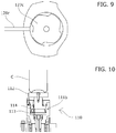
- Fig. 8 and Fig. 9 illustrate yet another form of the chuck unit in the seaming device of the present invention.
- a vane pump 127c that rotates with the rotation of the chuck 121c is provided above an oil seal 129c at the lowermost end of the chuck unit 120c, so that lubricating oil is discharged from a discharge tube 128c as the vane pump 127c rotates.
- the amount of lubricating oil stored above the oil seal 129c can be made minimum, so that lubricating oil leakage from the oil seal 129c or stain that may occur as the chuck 121c rotates can be prevented.
- Fig. 10 illustrates another form of the pressing mechanism 111 of the can placement unit 110 in the seaming device of the present invention.
- a mechanism that presses the plate 112 resiliently upward with a pressurized fluid such as compressed air may be used.
- This pressing mechanism 111b is formed with a piston 114 having the plate 112 fixed thereto and inserted in an upper part of a cylindrical space 113.
- the plate 112 is resiliently pressed upward by supplying a pressurized fluid such as compressed air into the cylindrical space 113.
- the pressing mechanism 111b With the use of the pressing mechanism 111b, a constant pressing force can be achieved in all the pockets P. Since the pressing force achieved is constant irrespective of the amount of lowering of the pressed-down plate 112, the adjustment is made very easy, and fluctuations during the operation can be prevented.
- the pressing mechanism 111b when the height of the can C decreases slightly during the seaming, the error between the cam profiles of the vertical motion cam 123 of the chuck unit 120 described above and the vertical motion cam 134 of the seaming unit 130 and the actual amount of decrease in the can height can be absorbed by the pressing mechanism 111b without causing axial load fluctuations.
- the seaming accuracy can thus be improved and operation speed can be increased.
- Fig. 11 illustrates a can placement unit 110c that has another form of the pressing mechanism.
- the pressing mechanism 111c includes a diaphragm 118c to keep the piston 114c for moving the plate 112c up and down airtight from the cylindrical space 113c.
Landscapes
- Engineering & Computer Science (AREA)
- Mechanical Engineering (AREA)
- Automation & Control Theory (AREA)
- Sealing Of Jars (AREA)
- Closing Of Containers (AREA)
Abstract
Description
- The present invention relates to a seaming device equipped with a can placement unit that places a can, a chuck unit provided opposite the can placement unit, and a seaming roll that seams a lid to the can.
- Seaming devices equipped with a can placement unit where cans filled with beverage are placed, a chuck unit provided opposite the can placement unit, and a seaming roll that seams lids to cans have hitherto been known.
- A known seaming device, for example as shown in Patent Literature 1, includes a seaming turret (1) that performs the process of seaming cans and lids, an infeed conveyor (supply conveyor 7) that supplies cans prior to seaming to the seaming turret, a lid transfer turret (supply turret 3) of a lid supply unit that supplies lids, a discharge turret (discharge turret 5) that carries the seamed cans out of the seaming turret, and an outfeed conveyor (discharge conveyor 8) that carries the cans out of the discharge turret further to the outside.
- The seaming turret, discharge turret, and lid transfer turret are each provided with pockets (fitting recesses 2, 4, and 6) in their outer peripheral parts for individually accommodating and transferring cans and lids.
- Each pocket of the seaming turret is provided with a can placement unit (lifter 17) where cans are placed, a chuck unit (seaming chuck device 10) provided opposite the can placement unit, and a seaming roll (18, 19) that seams lids to cans.
- Such a seaming device configured as described above is capable of continuous seaming of cans and lids as they are transferred from one place to another at high speed, with the respective turrets and conveyors operating at speeds and timings matched by means of gears or the like, and by the actions of the can placement unit, chuck unit, and seaming unit disposed in each pocket coordinated with the rotation of the seaming turret by means of gears, cam mechanisms and the like.
- Patent Literature 1: Japanese Patent Application Laid-open No.
S62-244537 - In such a known seaming device, the can placement unit (lifter) provided to each pocket of the seaming turret, and knockout pads, if any, are each lifted and lowered by a cam mechanism in coordination with the rotation of the seaming turret.
- When the can is supplied to each pocket of the seaming turret, the can placement unit (lifter) is lifted up to hold the can and lid between the lifter and the chuck to seam the lid on the can.
- The transfer of the can supplied from the infeed conveyor to the can placement unit (lifter) of the seaming turret for the seaming operation makes the posture of the can unstable. The can may hit a guide or a pocket of the seaming turret and dents may be created, which can result in buckling during the seaming.
- Cans vibrate slightly as they are transferred on the infeed conveyor. High-speed lifting of the can by the can placement unit makes its posture unstable and decenters the can, which similarly causes the can to hit a guide or a pocket of the seaming turret and dents to be created.
- The present invention solves the problems described above, its object being to provide a seaming device capable of preventing dents caused by a can guide or a seaming turret pocket, and buckling resulting from the dents during seaming, and capable of improving seaming accuracy, by stabilizing the posture of the can being transferred when the can is supplied from an infeed conveyor.
- The seaming device according to the present invention is a seaming device including a can placement unit that places a can, a chuck unit that is provided opposite the can placement unit, and a seaming unit that seams a lid to the can, the can placement unit including a pressing mechanism that presses a plate, on which the can is placed, resiliently upward, and the chuck unit and the seaming unit being configured to be capable of moving up and down, whereby the above problems are solved.
- According to the seaming device as set forth in claim 1, the can placement unit includes the pressing mechanism that presses the plate on which the can is placed resiliently upward, and the chuck unit and seaming unit are configured capable of moving up and down, so that the can placement unit need not be lifted or lowered in a state wherein the plate of the can placement unit is rotating. The can does not move up and down and stays stable when it is transferred from the infeed conveyor to the can placement unit. Therefore, dents caused by guides or pockets of the seaming turret, and buckling during seaming resulting from such dents are prevented, and the seaming accuracy can be improved.
- According to the configuration set forth in claim 2, the chuck unit and seaming unit are formed integrally so as to be moved up and down by a single cam mechanism. This can prevent changes in the positions of the chuck and seaming roll resulting from expansion caused by friction heat generated between a rotary shaft and an oil seal and the like, so that maintenance is made easy.
- According to the configuration set forth in claim 3, rotation of the plate of the can placement unit and rotation of the chuck of the chuck unit, and the seaming operation by the seaming roll of the seaming unit are achieved by driving sources that are independently controlled. The timing of starting or accelerating the rotation of the plate and chuck, and the timing of the seaming operation can be adjusted individually and optimally without stopping the operation by separate control of respective driving sources, so that the adjustment operation can be performed easily in a short time.
- According to the configuration set forth in claim 4, the seaming device includes an infeed conveyor that supplies cans to the seaming turret, and a lid supply unit made up of a lid feeder that feeds lids and a lid transfer turret. As the infeed conveyor, lid feeder, and lid transfer turret each have an independently controlled driving source, the operation timing can be adjusted individually and optimally in accordance with the size or weight of the can, seam size, etc., without stopping the operation, and the adjustment operation can be performed easily in a short time.
- According to the configuration set forth in claim 5, the driving sources are servomotors, so that adjustments can be made by electrical control commands, and feedback control is also possible. Thus the adjustment operation can be performed more easily in a short time.
- According to the configuration set forth in claim 6, cans on which lids have been placed are supplied to the seaming turret by the infeed conveyor, so that seaming is performed by the chuck unit and seaming unit without the need to lift and lower the plate of the can placement unit.
- According to the configuration set forth in claim 7, the chuck unit causes the chuck alone to make contact with the lid, and lowers the chuck for centering the lid and for pressing the lid, so that it is easier to correct the position of the lid. No eccentric load is applied so that buckling of the can is prevented, which enables a further reduction in the can thickness.
- According to the configuration set forth in claim 8, the chuck includes lid suction means. Since the chuck holds the lid by suction and increases the fitting force, seaming failures resulting from slippage are prevented. This enables a reduction in axial load applied to the can, so that buckling of the can is prevented, and can thickness can be reduced.
- The chuck holds the lid by suction with its lid suction means to achieve centering of the lid, and is lowered to place the lid on the can thereafter so that the seaming is performed by the chuck unit and seaming unit without the need to lift and lower the plate of the can placement unit.
- According to the configuration set forth in claim 9, the seaming turret includes detection means that detects the positions of the pockets. A pitch sensor that detects attachments of the infeed conveyor is provided on the transfer path of the infeed conveyor, so that the adjustment operation can be performed more easily. Also, automatic detection and correction of position errors, or position variations during operation, of each pocket or attachment, are made possible, so that the seaming accuracy can be improved and the speed of seaming operation can be increased.
- According to the configuration set forth in claim 10, the chuck unit includes a rotary vane pump that forcibly discharges lubricating oil, so that the amount of lubricating oil stored above the oil seal can be made minimum. Lubricating oil leakage from the oil seal or stain that may occur as the chuck rotates can be prevented.
- According to the configuration set forth in claim 11, the pressing mechanism of the can placement unit is configured to operate by fluid pressure, so that a constant pressing force can be achieved and the adjustment is made very easy. There is hardly any fluctuation, in particular, axial load fluctuation during the operation, even when the height of the can decreases slightly during the seaming and the amount of error from the actual amount of decrease in the can height is absorbed by the pressing mechanism. The seaming accuracy can thus be improved and the speed of seaming operation can be increased.
- According to the configuration set forth in claim 12, a diaphragm for sealing the fluid pressure is included, so that a sealing member that operates in sliding contact is made unnecessary. The plate can be lifted and lowered smoothly, as there is no seal resistance in the vertical movement.
-
- [
Fig. 1] Fig. 1 is a process illustration diagram of a seaming device according to one embodiment of the present invention. - [
Fig. 2] Fig. 2 is an illustrative diagram of a drive motor in each process. - [
Fig. 3] Fig. 3 is an illustrative diagram of a can placement unit, a chuck unit, and a seaming unit of the seaming device according to one embodiment of the present invention. - [
Fig. 4] Fig. 4 is an illustrative diagram of a chuck in the seaming device of the present invention. - [
Fig. 5] Fig. 5 is an illustrative diagram of another form of the chuck in the seaming device of the present invention. - [
Fig. 6] Fig. 6 is a process illustration diagram of a seaming device according to another embodiment of the present invention. - [
Fig. 7] Fig. 7 is an illustrative diagram of another form of the chuck unit and seaming unit in the seaming device according to the present invention. - [
Fig. 8] Fig. 8 is an enlarged illustrative diagram of yet another form of the chuck unit. - [
Fig. 9] Fig. 9 is a cross-sectional view ofFig. 8 . - [
Fig. 10] Fig. 10 is an illustrative diagram of another form of the pressing mechanism of the can placement unit in the seaming device of the present invention. - [
Fig. 11] Fig. 11 is an enlarged illustrative diagram of yet another form of the pressing mechanism of the can placement unit. -
- 100
- Seaming device
- 101
- Seaming turret
- 102
- Infeed conveyor
- 103
- Attachment
- 105
- Lid feeder
- 106
- Lid transfer turret
- 107
- Discharge turret
- 108
- Outfeed conveyor
- 110
- Can placement unit
- 111
- Pressing mechanism
- 112
- Plate
- 113
- Cylindrical space
- 114
- Piston
- 118
- Diaphragm
- 120
- Chuck unit
- 121
- Chuck
- 122
- Vertical motion mechanism of chuck unit
- 123
- Vertical motion cam of chuck unit
- 124
- Vertical motion cam follower of chuck unit
- 125
- Negative pressure suction hole (lid suction means)
- 126
- Chuck peripheral part
- 127
- Vane pump
- 128
- Discharge tube
- 129
- Oil seal
- 130
- Seaming unit
- 131
- Seaming roll
- 132
- Roll pivot shaft
- 133
- Vertical motion mechanism of seaming unit
- 134
- Vertical motion cam of seaming unit
- 135
- Vertical motion cam follower of seaming unit
- 136
- Integral housing for chuck and roll
- 156
- Chuck drive motor (driving source)
- 157
- Drive motor of can placement unit (driving source)
- 158
- Drive motor of roll pivot shaft (driving source)
- C
- Can (before seaming)
- F
- Lid
- CM
- Can (after seaming)
- P
- K
- Spline
- E
- Seaming zone
- The seaming
device 100 according to one embodiment of the present invention includes, as shown inFig. 1 , a seamingturret 101 that performs the process of seaming cans C and lids F, aninfeed conveyor 102 that supplies cans C on which lids F have been placed to the seamingturret 101, alid feeding unit 104 composed of alid feeder 105 that supplies lids F and alid transfer turret 106, adischarge turret 107 that carries the seamed cans CM out of the seamingturret 101, and anoutfeed conveyor 108 that carries the cans CM out of thedischarge turret 107 further to the outside. - Cans C on which lids F have been placed are supplied to the seaming
turret 101 by theinfeed conveyor 102, so that seaming is performed by achuck unit 120 and a seamingunit 130 without the necessity to lift and lower theplate 112 of thecan placement unit 110 to be described later. - The seaming
turret 101,discharge turret 107, andlid transfer turret 106 are each provided with pockets P in their outer peripheral parts for individually accommodating and transferring the cans C or CM and lids F. Theinfeed conveyor 102 is provided withattachments 103 that individually engage with and transfer cans C. - The rotation speeds of the seaming
turret 101,discharge turret 107, andlid transfer turret 106, the moving speed of theattachments 103 of theinfeed conveyor 102, and coordinated timing of each pocket P andattachment 103 are designed adjustable so that the cans C or CM and lids F are smoothly transferred between respective turrets and conveyors. - The seaming
turret 101 that performs the process of seaming cans C and lids F includes, as shown inFig. 3 , acan placement unit 110 where cans C are placed, achuck unit 120 provided opposite thecan placement unit 110, and a seamingunit 130 having a seamingroll 131 that seams the lid F to the can C, in each of the pockets P. - The seaming
turret 101 is configured to be rotated by adrive motor 151 of the seaming turret, and the pocket positions can be detected by a pocketposition detection encoder 155 from the rotation phases. - A pitch sensor S made up of a phototube, proximity switch, laser and the like is provided on a transfer path of the
infeed conveyor 102 for detecting the positions of theattachments 103 of theinfeed conveyor 102. The positions of theattachments 103 relative to the pockets P of the seamingturret 101 andlid transfer turret 106 are controlled based on the outputs of this pitch sensor S. - Such detection and control can further facilitate adjustment operations, as well as enable automatic detection and correction of position errors, or position variations during operation, of each pocket P or
attachment 103, so that the seaming accuracy can be improved and the speed of seaming operation can be increased. Thelid feeder 105,lid transfer turret 106, andinfeed conveyor 102 are driven by adrive motor 153 of thelid feeder 105, adrive motor 152 of thelid transfer turret 106, and adrive motor 154 of theinfeed conveyor 102, respectively, as shown inFig. 2 . - Servomotors are adopted as these motors, which are configured such that the speed and timing are individually adjustable, and that they are capable of following speed and timing fluctuations of the seaming
turret 101, in accordance with the outputs of the pocketposition detection encoder 155. - As the
lid feeder 105,lid transfer turret 106, andinfeed conveyor 102 are each driven by independently controlled driving sources, the operation timing can be adjusted individually and optimally in accordance with the size or weight of the can, seam size, etc., without stopping the operation, and the adjustment operation can be performed easily in a short time. - Since the driving sources are servomotors, adjustments can be made by electrical control commands, and feedback control is also possible. Thus the adjustment operation can be performed more easily in a short time.
- Since the
discharge turret 107 andoutfeed conveyor 108 transfer only seamed cans CM and mismatches in their speed and timing are tolerated to some extent, any suitable driving sources may be used, as represented by drive force transmitted mechanically via a transmission mechanism from thedrive motor 151 of the seamingturret 101. - Any suitable driving sources, as represented by drive force transmitted mechanically via a transmission mechanism from the
drive motor 151 of the seamingturret 101, may be used also for thelid feeder 105,lid transfer turret 106, andinfeed conveyor 102, as long as they are designed such that the speed and timing are easily adjustable in terms of accuracy and speed. - The
can placement unit 110 includes aplate 112 on which a can C is placed, and apressing mechanism 111 that presses theplate 112 resiliently upward with a spring, compressed air, and the like. - The
can placement unit 110 is configured not to move up and down except for theplate 112 being moved up and down by thepressing mechanism 111. - The
chuck unit 120 moves up and down by means of avertical motion mechanism 122 of thechuck unit 120 made up of avertical motion cam 123 and a verticalmotion cam follower 124 as shown inFig. 3 . - The
vertical motion cam 123 of thechuck unit 120 is fixedly provided, so that, as the seamingturret 101 rotates, the verticalmotion cam follower 124 of thechuck unit 120 moves in conformity to the cam profile to cause thechuck 121 in thechuck unit 120 to move up and down at corresponding positions. - The width (thickness) of a gear each attached to the
chuck unit 120 and thedrive motor 156 of thechuck 121 to be described later is set suitably to control the rotation of thechuck 121 by thedrive motor 156 in the up and down movement of thechuck unit 120. - This control of rotation can be achieved by adopting or adding suitable means.
- Meanwhile, the seaming
roll 131 of the seamingunit 130 similarly moves up and down by means of avertical motion mechanism 133 of the seamingunit 130 made up of avertical motion cam 134 and a verticalmotion cam follower 135 as shown inFig. 3 . - The
vertical motion cam 134 of the seamingunit 130 is fixedly provided, so that, as the seamingturret 101 rotates, the verticalmotion cam follower 135 of the seamingunit 130 moves in conformity to the cam profile to cause the seamingunit 130 to move up and down at corresponding positions. - The seaming
unit 130 includes a spline K above aroll pivot shaft 132 to enable extension/contraction and rotation of theroll pivot shaft 132. Thus the seamingroll 131 is moved up and down by thevertical motion mechanism 133 mentioned above, as well as the seaming operation and pressing by the seamingroll 131 are achieved by thedrive motor 158 of theroll pivot shaft 132 to be described later. - Means for enabling vertical motion, seaming operation, and pressing of the seaming
roll 131 are not necessarily limited to the spline K or the like of theroll pivot shaft 132, and any suitable means may be adopted or added. - Since the
can placement unit 110 includes thepressing mechanism 111 that presses theplate 112 on which the can is placed resiliently upward, and since thechuck unit 120 and seamingunit 130 can move up and down, thecan placement unit 110 need not be lifted or lowered in a state wherein theplate 112 is rotating. The can C does not move up and down and stays stable when it is transferred from theinfeed conveyor 102 to thecan placement unit 110. Therefore, dents caused by guides or pockets P of the seamingturret 101, and buckling during seaming resulting from such dents are prevented, and the seaming accuracy can be improved. - The driving sources for the rotation of the
plate 112 of thecan placement unit 110 and thechuck 121 of thechuck unit 120 are thedrive motor 157 of thecan placement unit 110 and thedrive motor 156 of thechuck 121, respectively, which are independently controlled servomotors, as shown inFig. 3 . - Such driving allows independent control of the timing of starting or accelerating rotation of the
plate 112 and chuck 121 for individual optimal adjustment without stopping the operation by an operation panel or the like, so that the adjustment operation can be performed easily in a short time, and fluctuations can be dealt with during the operation. - By controlling the timing of starting or accelerating rotation of the
plate 112 and chuck 121, the rotation of theplate 112 and chuck 121 can be stopped or slowed down when fitting therotating chuck 121 with the lid placed on the can, to reduce misalignment between the rotation centers, whereby dents, scratches, or the like on the can caused by contact with guide members or the like are prevented, and also, the lid centering performance of thechuck 121 can be improved. - On the other hand, the driving source of the
roll pivot shaft 132 of the seamingunit 130 is thedrive motor 158 of theroll pivot shaft 132 which is an independently controlled servomotor. The timing of the seaming operation or amount of pressure applied by the seamingroll 131 can be independently controlled and individually optimally adjusted without stopping the operation by an operation panel or the like, so that the adjustment operation can be performed easily in a short time, and fluctuations can be dealt with during the operation. - As mentioned above, the driving sources for rotating the
plate 112 and chuck 121 and for theroll pivot shaft 132 are servomotors, so that adjustments can be made by electrical control commands, and feedback control is also possible. Thus the adjustment operation can be performed more easily in a short time. - The
chuck unit 120 includes thechuck 121 that presses the lid F as shown inFig. 4 . Centering of the lid F is achieved by thechuck 121 coming down with its chuckperipheral part 126 fitting with the lid F placed on the can C that has been supplied to the seamingturret 101, so that the seaming is performed by thechuck unit 120 and seamingunit 130, without the need to lift and lower theplate 112 of thecan placement unit 110. - Since the
chuck 121 performs centering of the lid F placed on the can C as well as presses the lid F in this way, it is easier to correct the position of the lid F. No eccentric load is applied so that buckling of the can is prevented, which enables a further reduction in the can thickness. - In another form of the
chuck 121 shown inFig. 5 , thechuck 121 is formed with a negativepressure suction hole 125, so that thechuck 121 holds the lid F by suction for the centering. - The speed and timing of the
infeed conveyor 102 andlid transfer turret 106 are normally adjusted in accordance with the speed and timing of the seamingturret 101 such that the centers of the can C and lid F coincide with each other at a meeting point G as shown inFig. 6 . - In this embodiment, the
lid transfer turret 106 is disposed such that the lid F is picked up by thechuck 121 by negative pressure suction at a position Gb upstream of the normal meeting point G relative to the seamingturret 101. At this upstream position Gb where thechuck 121 picks up the lid F by negative pressure suction, the lid F is held by negative pressure suction and centered by thechuck 121, whose rotation is controlled with a drive motor (servomotor) 156. - After the
chuck 121 holds the lid F by suction, it is lowered to place the lid F on the can C. Seaming is thus performed by thechuck unit 120 and seamingunit 130 without the need to lift and lower theplate 112 of thecan placement unit 110. - The
chuck 121 holds the lid F by negative pressure suction for the centering in this way to fit the chuckperipheral part 126 with the lid F. As thechuck 121 holds the lid F by suction in advance to increase the fitting force, seaming failures resulting from slippage are prevented. This enables a reduction in axial load applied to the can C, so that can C buckling is prevented, and can thickness can be reduced. - Also, since the centering of the lid F has been reliably achieved by the suction hold of the
chuck 121 when the lid F is placed on the can C, buckling caused by an eccentric load is prevented. - The operation of the seaming
device 100 configured as described above will be explained. - Cans C before lids F are seamed are transferred by the
infeed conveyor 102 in engagement with eachattachment 103 toward the seamingturret 101. - On the other hand, lids F are cut out one each from the
lid feeder 105, handed over to each pocket P of thelid transfer turret 106, and travel to above the can C (seeFig. 1 ) by the rotation of thelid transfer turret 106. - The speed and timing of the
infeed conveyor 102 andlid transfer turret 106 are coordinated in accordance with the speed and timing of the seamingturret 101 such that the centers of a can C and a lid F coincide with each other at a predetermined position on theinfeed conveyor 102, and the lid F drops down to the can C at the predetermined position. Thus the lid F is placed on the can C on theinfeed conveyor 102. - After that, the can C with the lid F thereon is transferred from the
infeed conveyor 102 to the seamingturret 101, where it is placed on theplate 112 of thecan placement unit 110, whose rotation is controlled by the drive motor (servomotor) 157 of thecan placement unit 110. - Next, the
chuck unit 120, whose rotation is controlled by the drive motor (servomotor) 156, is lowered by thevertical motion mechanism 122, to fit thechuck 121 of thechuck unit 120 with the lid F. - The can C with the lid F fitted therewith is held between the
plate 112 and thechuck 121, with a constant axial load necessary for the seaming being applied thereto against the pressure applied by thepressing mechanism 111 of thecan placement unit 110. At the same time, centering of the lid F is achieved by thechuck 121, and centering of the can C fitted therewith is also achieved. - As mentioned before, the centering of the lid F by the
chuck 121 and placement of the lid F on the can C may be performed such that thechuck 121 provided with the negativepressure suction hole 125 of suction means holds the lid F by suction and performs centering of the lid F, and after the suction hold, thechuck 121 is lowered to place the lid F on the can C. - The seaming
turret 101 is rotated further, and accelerated to an rpm necessary for the seaming before the lid F and can C being sandwiched reach the seaming zone E shown inFig. 1 . - Meanwhile, the seaming
unit 130 is lowered by thevertical motion mechanism 133 to position the seamingroll 131 at a seaming section of the can C with the lid F fitted thereon. As they travel through the seaming zone E, theroll pivot shaft 132 of the seamingunit 130 is actuated by the drive motor (servomotor) 158 to press the seamingroll 131 from a side to perform the seaming. - Although only one seaming
roll 131 is shown in the drawings, there are actually provided two seaming rolls 131 on theroll pivot shaft 132 for primary seaming operation and secondary seaming operation, these being pressed to the can and lid one after another as they travel through the seaming zone E for completing the seaming. - The seamed can CM is handed over from the seaming
turret 101 to thedischarge turret 107, and further from thedischarge turret 107 to theoutfeed conveyor 108 to be carried out to a next process such as inspection, packaging and the like. -
Fig. 7 illustrates another form of the chuck unit and seaming unit in the seaming device of the present invention, wherein thechuck unit 120b and seamingunit 130b are made integral with each other by ahousing 136, so that thechuck 121 and seamingroll 131 move integrally up and down by avertical motion mechanism 143 of thechuck unit 120b and seamingunit 130b, which is made up of avertical motion cam 144 and a verticalmotion cam follower 145. - This configuration enables improvement of accuracy in the vertical positional relationship between the
chuck unit 120b and the seamingunit 130b, and prevents misalignment in the vertical positions between thechuck unit 120b and seamingunit 130b caused by thermal deformation or the like, whereby the seaming accuracy can be improved and the operation speed can be increased. -
Fig. 8 andFig. 9 illustrate yet another form of the chuck unit in the seaming device of the present invention. As shown in the drawing, avane pump 127c that rotates with the rotation of thechuck 121c is provided above anoil seal 129c at the lowermost end of thechuck unit 120c, so that lubricating oil is discharged from adischarge tube 128c as thevane pump 127c rotates. - This way, the amount of lubricating oil stored above the
oil seal 129c can be made minimum, so that lubricating oil leakage from theoil seal 129c or stain that may occur as thechuck 121c rotates can be prevented. -
Fig. 10 illustrates another form of thepressing mechanism 111 of thecan placement unit 110 in the seaming device of the present invention. As shown in the drawing, a mechanism that presses theplate 112 resiliently upward with a pressurized fluid such as compressed air may be used. - This
pressing mechanism 111b is formed with apiston 114 having theplate 112 fixed thereto and inserted in an upper part of acylindrical space 113. Theplate 112 is resiliently pressed upward by supplying a pressurized fluid such as compressed air into thecylindrical space 113. - With the use of the
pressing mechanism 111b, a constant pressing force can be achieved in all the pockets P. Since the pressing force achieved is constant irrespective of the amount of lowering of the pressed-downplate 112, the adjustment is made very easy, and fluctuations during the operation can be prevented. - With the use of the
pressing mechanism 111b, when the height of the can C decreases slightly during the seaming, the error between the cam profiles of thevertical motion cam 123 of thechuck unit 120 described above and thevertical motion cam 134 of the seamingunit 130 and the actual amount of decrease in the can height can be absorbed by thepressing mechanism 111b without causing axial load fluctuations. The seaming accuracy can thus be improved and operation speed can be increased. -
Fig. 11 illustrates acan placement unit 110c that has another form of the pressing mechanism. As shown in the drawing, thepressing mechanism 111c includes adiaphragm 118c to keep thepiston 114c for moving theplate 112c up and down airtight from thecylindrical space 113c. - This way, the
piston 114c can move up and down without seal resistance, so that theplate 112c can be lifted and lowered smoothly.
Claims (12)
- A seaming device comprising a can placement unit that places a can, a chuck unit that is provided opposite the can placement unit, and a seaming unit that seams a lid to the can,
the can placement unit including a pressing mechanism that presses a plate, on which a can is placed, resiliently upward, and
the chuck unit and the seaming unit being configured to be capable of moving up and down. - The seaming device according to claim 1, wherein the chuck unit and the seaming unit are formed integrally so as to move up and down by a single cam mechanism.
- The seaming device according to claim 1 or 2, wherein rotation of the plate of the can placement unit and rotation of a chuck of the chuck unit, and seaming operation by a seaming roll of the seaming unit are implemented by independently controlled driving sources.
- The seaming device according to any one of claims 1 to 3, further comprising an infeed conveyor that supplies cans to a seaming turret, and a lid feeding unit configured of a lid feeder that supplies lids and a lid transfer turret, wherein the infeed conveyor, lid feeder, and lid transfer turret each have an independently controlled driving source.
- The seaming device according to claim 3 or 4, wherein the driving sources are servomotors.
- The seaming device according to claim 4, wherein cans on which lids have been placed are supplied to the seaming turret by the infeed conveyor.
- The seaming device according to claim 1, wherein the chuck unit causes the chuck alone to make contact with a lid, and lowers the chuck to perform centering of the lid and pressing of the lid.
- The seaming device according to any one of claims 1 to 5, wherein the chuck includes lid suction means and performs centering of the lid with the lid suction means, and after picking up the lid by suction, the chuck is lowered to place the lid on the can.
- The seaming device according to any one of claims 4 to 8, wherein the seaming turret includes detection means for detecting positions of pockets,
the seaming device further comprising a pitch sensor that detects attachments of the infeed conveyor on a transfer path of the infeed conveyor,
speed of the infeed conveyor being controlled, based on outputs of the detection means, and
positions of the attachments relative to pockets of the seaming turret and of the lid transfer turret being controlled based on output of the pitch sensor. - The seaming device according to any one of claims 1 to 9, wherein the chuck unit includes a rotary vane pump mechanism that forcibly discharges lubricating oil.
- The seaming device according to any one of claims 1 to 10, wherein the pressing mechanism is configured to be operated by fluid pressure.
- The seaming device according to claim 11, wherein the pressing mechanism includes a diaphragm that seals the fluid pressure.
Applications Claiming Priority (4)
| Application Number | Priority Date | Filing Date | Title |
|---|---|---|---|
| JP2015119614 | 2015-06-12 | ||
| JP2015137411 | 2015-07-09 | ||
| JP2016008012A JP6877875B2 (en) | 2015-06-12 | 2016-01-19 | Winding device |
| PCT/JP2016/066272 WO2016199649A1 (en) | 2015-06-12 | 2016-06-01 | Seaming device |
Publications (2)
| Publication Number | Publication Date |
|---|---|
| EP3308872A1 true EP3308872A1 (en) | 2018-04-18 |
| EP3308872A4 EP3308872A4 (en) | 2019-01-23 |
Family
ID=57828909
Family Applications (1)
| Application Number | Title | Priority Date | Filing Date |
|---|---|---|---|
| EP16807356.7A Withdrawn EP3308872A4 (en) | 2015-06-12 | 2016-06-01 | CRIMPING DEVICE |
Country Status (5)
| Country | Link |
|---|---|
| US (1) | US20180065168A1 (en) |
| EP (1) | EP3308872A4 (en) |
| JP (2) | JP6877875B2 (en) |
| CN (1) | CN107635689A (en) |
| TW (1) | TW201703897A (en) |
Cited By (2)
| Publication number | Priority date | Publication date | Assignee | Title |
|---|---|---|---|---|
| CN112238327A (en) * | 2019-07-17 | 2021-01-19 | 宁波安拓实业有限公司 | Corner passing transition joint machining process |
| IT202000016963A1 (en) * | 2020-07-13 | 2022-01-13 | Bonicomm S R L | CAN SEAMPING STATION AND CAN SEAMPING PROCESS IN A CAN SEAMPING STATION |
Families Citing this family (10)
| Publication number | Priority date | Publication date | Assignee | Title |
|---|---|---|---|---|
| US10195657B1 (en) * | 2016-05-03 | 2019-02-05 | Norland International, Inc. | Servo-driven seamer assembly for sealing a container |
| JP6291536B2 (en) * | 2016-08-04 | 2018-03-14 | 東洋製罐株式会社 | Winding device |
| CN109482768B (en) * | 2018-12-06 | 2023-10-03 | 江苏奥瑞金包装有限公司 | Tank production line and flanging and sealing device thereof |
| JP7621063B2 (en) | 2020-03-13 | 2025-01-24 | 東洋製罐グループエンジニアリング株式会社 | Sealing device |
| CN115279510B (en) * | 2020-03-13 | 2025-06-03 | 东洋制罐集团工程株式会社 | Sealing device |
| US12686047B2 (en) | 2020-09-21 | 2026-07-21 | Ferrum Packaging Ag | Seaming shaft arrangement for a sealer |
| US20240025603A1 (en) * | 2020-10-30 | 2024-01-25 | C-Loop Packaging Sweden Ab | Patterned can end modular dispensing systems with enhanced recyclability |
| USD1068472S1 (en) | 2023-05-01 | 2025-04-01 | C-Loop Packaging Sweden Ab | Can end |
| US20250296140A1 (en) * | 2023-06-28 | 2025-09-25 | Pneumatic Scale Corporation | Can closing machine |
| CN117602148B (en) * | 2023-10-23 | 2025-12-16 | 江苏仅一联合智造有限公司 | Servo power seaming device and can sealing machine using same |
Family Cites Families (21)
| Publication number | Priority date | Publication date | Assignee | Title |
|---|---|---|---|---|
| JPS5518594Y2 (en) * | 1974-02-14 | 1980-04-30 | ||
| US3902438A (en) * | 1974-02-22 | 1975-09-02 | Container Corp | Air-loaded base plate for can seamer |
| JPS62187530A (en) * | 1986-02-12 | 1987-08-15 | Toyo Seikan Kaisha Ltd | Can centering method in seaming device and can lid used therein |
| JPS62244537A (en) * | 1986-04-17 | 1987-10-24 | Toyo Seikan Kaisha Ltd | Method and device for seaming can |
| JPS635833A (en) * | 1986-06-27 | 1988-01-11 | Toyo Seikan Kaisha Ltd | Lifter for seaming device |
| JPS6418538A (en) * | 1987-07-14 | 1989-01-23 | Toyo Seikan Kaisha Ltd | Straight-line can seaming equipment |
| JPS6418540A (en) * | 1987-07-14 | 1989-01-23 | Toyo Seikan Kaisha Ltd | Straight-line can seaming equipment |
| JPH0761513B2 (en) * | 1988-04-27 | 1995-07-05 | 北海製罐株式会社 | Method and device for winding can lid |
| JP2572526B2 (en) * | 1993-06-16 | 1997-01-16 | 東洋食品機械株式会社 | Oiling device for can winding machine |
| CN1162279A (en) * | 1994-11-03 | 1997-10-15 | 卡努德金属制品有限公司 | Seaming apparatus |
| GB9422228D0 (en) * | 1994-11-03 | 1994-12-21 | Metal Box Plc | Seaming method and apparatus |
| JP2845158B2 (en) * | 1995-02-27 | 1999-01-13 | 東洋製罐株式会社 | Can lid supply guide rail in can winding machine |
| JP4026231B2 (en) * | 1998-05-28 | 2007-12-26 | 東洋製罐株式会社 | Inner scavenging device for lid at Cima |
| CN1173855C (en) * | 2000-03-06 | 2004-11-03 | 朱根龙 | Automatic cover blanking machine for top pop can with sucking tube |
| JP2001259766A (en) * | 2000-03-23 | 2001-09-25 | Mitsuba Denyosha:Kk | Can body manufacturing equipment |
| JP3991571B2 (en) * | 2000-10-02 | 2007-10-17 | 東洋製罐株式会社 | Aseptic filling negative pressure can manufacturing method and apparatus |
| JP4756183B2 (en) * | 2005-07-07 | 2011-08-24 | 新里機工株式会社 | A method of tightening the bottom plate (top plate) around the NC servo seamer and rectangular cube-shaped can body |
| JP5380104B2 (en) * | 2008-02-19 | 2014-01-08 | ユニバーサル製缶株式会社 | Can winding apparatus and can manufacturing method |
| ITMI20081508A1 (en) * | 2008-08-08 | 2010-02-09 | Zanichelli Meccanica Spa | DEVICE FOR THE INCREASE OF QUALITY CONTROL DURING A CRIMPING PROCESS. |
| JP2012096250A (en) * | 2010-10-29 | 2012-05-24 | Kirin Brewery Co Ltd | Deterioration control method of seaming chuck |
| CN202283573U (en) * | 2010-11-30 | 2012-06-27 | 东莞市铖泰制罐设备有限公司 | Multi-wheel seaming device of automatic can seamer |
-
2016
- 2016-01-19 JP JP2016008012A patent/JP6877875B2/en active Active
- 2016-05-27 JP JP2016106156A patent/JP6877891B2/en active Active
- 2016-05-31 TW TW105117014A patent/TW201703897A/en unknown
- 2016-06-01 CN CN201680032737.9A patent/CN107635689A/en active Pending
- 2016-06-01 EP EP16807356.7A patent/EP3308872A4/en not_active Withdrawn
-
2017
- 2017-11-14 US US15/811,934 patent/US20180065168A1/en not_active Abandoned
Cited By (3)
| Publication number | Priority date | Publication date | Assignee | Title |
|---|---|---|---|---|
| CN112238327A (en) * | 2019-07-17 | 2021-01-19 | 宁波安拓实业有限公司 | Corner passing transition joint machining process |
| IT202000016963A1 (en) * | 2020-07-13 | 2022-01-13 | Bonicomm S R L | CAN SEAMPING STATION AND CAN SEAMPING PROCESS IN A CAN SEAMPING STATION |
| WO2022013661A1 (en) * | 2020-07-13 | 2022-01-20 | Bonicomm S.R.L. | Can seaming station and can seaming process in a seaming station |
Also Published As
| Publication number | Publication date |
|---|---|
| JP2017013126A (en) | 2017-01-19 |
| CN107635689A (en) | 2018-01-26 |
| JP6877875B2 (en) | 2021-05-26 |
| TW201703897A (en) | 2017-02-01 |
| US20180065168A1 (en) | 2018-03-08 |
| JP2017013120A (en) | 2017-01-19 |
| EP3308872A4 (en) | 2019-01-23 |
| JP6877891B2 (en) | 2021-05-26 |
Similar Documents
| Publication | Publication Date | Title |
|---|---|---|
| US20180065168A1 (en) | Seaming device | |
| US10576530B2 (en) | Holding mechanism | |
| US20180078991A1 (en) | Seaming device | |
| CN217971647U (en) | Pile up neatly equipment tears open | |
| EP2754510B1 (en) | Method for seaming can cover | |
| CN106347923A (en) | Sheet material feeding apparatus | |
| US11618599B2 (en) | Strapping machine including an edge-protector magazine having a telescopic rail assembly | |
| WO2016199649A1 (en) | Seaming device | |
| JP6679968B2 (en) | Winding device | |
| US10730097B2 (en) | Method and device for feeding a sheet metal panel to a punch press | |
| JP6671185B2 (en) | Winding device | |
| EP4119254A1 (en) | Container member supply device | |
| CN108689366A (en) | The conveyor module and processing unit of transport box and the method for transport box | |
| WO2016199648A1 (en) | Seaming device | |
| JP6671186B2 (en) | Winding device | |
| GB2042373A (en) | Applying gaskets to container closure members | |
| CN216548578U (en) | Cover lower cover device and system | |
| CN109139720B (en) | Cage ball adding device applied to hub bearing | |
| CN216888783U (en) | Bottle unscrambler with adjustable longitudinal size of bottle unscrambling groove | |
| US20190160516A1 (en) | Seaming device | |
| EP4119255B1 (en) | Seaming device | |
| JP2009061509A (en) | Servomotor driving type tandem press line | |
| CN118205774A (en) | Continuous high-speed film sealing mechanism and film sealing machine | |
| JP2025102244A (en) | Cap tightening mechanism | |
| CN114194760A (en) | A bottle unscrambler with adjustable longitudinal dimension of bottle unscrambler |
Legal Events
| Date | Code | Title | Description |
|---|---|---|---|
| STAA | Information on the status of an ep patent application or granted ep patent |
Free format text: STATUS: THE INTERNATIONAL PUBLICATION HAS BEEN MADE |
|
| PUAI | Public reference made under article 153(3) epc to a published international application that has entered the european phase |
Free format text: ORIGINAL CODE: 0009012 |
|
| STAA | Information on the status of an ep patent application or granted ep patent |
Free format text: STATUS: REQUEST FOR EXAMINATION WAS MADE |
|
| 17P | Request for examination filed |
Effective date: 20171222 |
|
| AK | Designated contracting states |
Kind code of ref document: A1 Designated state(s): AL AT BE BG CH CY CZ DE DK EE ES FI FR GB GR HR HU IE IS IT LI LT LU LV MC MK MT NL NO PL PT RO RS SE SI SK SM TR |
|
| AX | Request for extension of the european patent |
Extension state: BA ME |
|
| DAV | Request for validation of the european patent (deleted) | ||
| DAX | Request for extension of the european patent (deleted) | ||
| RIC1 | Information provided on ipc code assigned before grant |
Ipc: B21D 51/32 20060101ALI20181213BHEP Ipc: B21D 37/18 20060101ALN20181213BHEP Ipc: B21D 51/30 20060101AFI20181213BHEP |
|
| A4 | Supplementary search report drawn up and despatched |
Effective date: 20190102 |
|
| RIC1 | Information provided on ipc code assigned before grant |
Ipc: B21D 37/18 20060101ALN20190906BHEP Ipc: B21D 51/32 20060101ALI20190906BHEP Ipc: B21D 51/30 20060101AFI20190906BHEP |
|
| GRAP | Despatch of communication of intention to grant a patent |
Free format text: ORIGINAL CODE: EPIDOSNIGR1 |
|
| STAA | Information on the status of an ep patent application or granted ep patent |
Free format text: STATUS: GRANT OF PATENT IS INTENDED |
|
| RIC1 | Information provided on ipc code assigned before grant |
Ipc: B21D 37/18 20060101ALN20190926BHEP Ipc: B21D 51/30 20060101AFI20190926BHEP Ipc: B21D 51/32 20060101ALI20190926BHEP |
|
| INTG | Intention to grant announced |
Effective date: 20191029 |
|
| STAA | Information on the status of an ep patent application or granted ep patent |
Free format text: STATUS: THE APPLICATION IS DEEMED TO BE WITHDRAWN |
|
| 18D | Application deemed to be withdrawn |
Effective date: 20200310 |