EP3308845A1 - Media retention screen for adsorption canister - Google Patents
Media retention screen for adsorption canister Download PDFInfo
- Publication number
- EP3308845A1 EP3308845A1 EP17196762.3A EP17196762A EP3308845A1 EP 3308845 A1 EP3308845 A1 EP 3308845A1 EP 17196762 A EP17196762 A EP 17196762A EP 3308845 A1 EP3308845 A1 EP 3308845A1
- Authority
- EP
- European Patent Office
- Prior art keywords
- portions
- support pad
- outer edge
- set forth
- retention screen
- Prior art date
- Legal status (The legal status is an assumption and is not a legal conclusion. Google has not performed a legal analysis and makes no representation as to the accuracy of the status listed.)
- Granted
Links
Images



Classifications
-
- B—PERFORMING OPERATIONS; TRANSPORTING
- B01—PHYSICAL OR CHEMICAL PROCESSES OR APPARATUS IN GENERAL
- B01D—SEPARATION
- B01D53/00—Separation of gases or vapours; Recovering vapours of volatile solvents from gases; Chemical or biological purification of waste gases, e.g. engine exhaust gases, smoke, fumes, flue gases, aerosols
- B01D53/02—Separation of gases or vapours; Recovering vapours of volatile solvents from gases; Chemical or biological purification of waste gases, e.g. engine exhaust gases, smoke, fumes, flue gases, aerosols by adsorption, e.g. preparative gas chromatography
- B01D53/04—Separation of gases or vapours; Recovering vapours of volatile solvents from gases; Chemical or biological purification of waste gases, e.g. engine exhaust gases, smoke, fumes, flue gases, aerosols by adsorption, e.g. preparative gas chromatography with stationary adsorbents
- B01D53/0407—Constructional details of adsorbing systems
-
- B—PERFORMING OPERATIONS; TRANSPORTING
- B01—PHYSICAL OR CHEMICAL PROCESSES OR APPARATUS IN GENERAL
- B01J—CHEMICAL OR PHYSICAL PROCESSES, e.g. CATALYSIS OR COLLOID CHEMISTRY; THEIR RELEVANT APPARATUS
- B01J19/00—Chemical, physical or physico-chemical processes in general; Their relevant apparatus
- B01J19/30—Loose or shaped packing elements, e.g. Raschig rings or Berl saddles, for pouring into the apparatus for mass or heat transfer
- B01J19/305—Supporting elements therefor, e.g. grids, perforated plates
-
- F—MECHANICAL ENGINEERING; LIGHTING; HEATING; WEAPONS; BLASTING
- F02—COMBUSTION ENGINES; HOT-GAS OR COMBUSTION-PRODUCT ENGINE PLANTS
- F02M—SUPPLYING COMBUSTION ENGINES IN GENERAL WITH COMBUSTIBLE MIXTURES OR CONSTITUENTS THEREOF
- F02M25/00—Engine-pertinent apparatus for adding non-fuel substances or small quantities of secondary fuel to combustion-air, main fuel or fuel-air mixture
- F02M25/08—Engine-pertinent apparatus for adding non-fuel substances or small quantities of secondary fuel to combustion-air, main fuel or fuel-air mixture adding fuel vapours drawn from engine fuel reservoir
- F02M25/0854—Details of the absorption canister
-
- B—PERFORMING OPERATIONS; TRANSPORTING
- B01—PHYSICAL OR CHEMICAL PROCESSES OR APPARATUS IN GENERAL
- B01D—SEPARATION
- B01D2259/00—Type of treatment
- B01D2259/45—Gas separation or purification devices adapted for specific applications
- B01D2259/4516—Gas separation or purification devices adapted for specific applications for fuel vapour recovery systems
Definitions
- This application relates to a retention screen for use in an adsorption canister housing.
- Adsorption systems typically include a canister housing with opposed covers. Within the canister, adsorption media, such as pellets, is deposited. The pellets may also be referred to as beads. Screens are typically placed inwardly of each of the covers to retain the beads in an enclosed area.
- a gas to be treated is passed over the beads and certain beneficial functions occur.
- the beads may remove carbon dioxide from air for use in an inhabited vehicle. At some point, the beads must be desorbed. Thus, a vacuum is applied.
- the prior art retention screens have typically used standard woven screen materials.
- the forces applied, in particular, during the vacuum desorbing function, have raised challenges on the screen. It is often the case that beads may be forced through the screen material, which is undesirable.
- the beads must periodically be replaced. During such maintenance, the screen material may be damaged.
- seals are typically provided around the edge of the screen to ensure the bulk of the gas flow does pass through the beads. In the prior art, the seals also raise challenges.
- a retention screen for use in an adsorption canister has outer edges including a seal groove that form a relatively thick portion and a plurality of support pad portions also formed to be relatively thick and relatively thin connecting web portions connecting the outer edge to the support pad portions.
- the connecting web portions also connect the support pad portions to each other.
- the retention screen is generally planar. The edge portions and the support pad portions are thicker than the connecting web portions.
- An adsorption system and a method of manufacture are also disclosed.
- FIG 1 schematically shows a manned vehicle 19 that may include an desorption system 20.
- Such systems may be utilized for processing breathing air and, in particular, for removing carbon dioxide.
- a top cover 22 is spaced by a canister housing 24 from a bottom cover 26.
- Retention screens 28 and 30 define an enclosed media spaces between them.
- a support brace 34 extends between the screens. The support brace provides a force resisting flexing of the screens 28 and 30 as gas passes across the space or a vacuum is drawn.
- a number of support plates 36 are also included. The support plates help keep the covers at top and bottom from collapsing inward when the vacuum is drawn. The plates provide compression load support.
- a media 38 which may be beads of adsorption material is placed within the space.
- Gas 40 may pass across the spaces and exit at 42 having been processed.
- a desorb function may also be applied such as shown schematically with a vacuum 44 drawn on the spaces.
- a disclosed screen 57 has several improved structural features.
- the screen 57 may be manufactured as a one piece item, such as by additive manufacturing techniques.
- the bottom cover 26 is shown, however, the top cover 22 and its screen 30 may be a mirror image.
- the retention screen 57 includes an outer edge portion 52 which is generally thick and sits against a pedestal 48 on the bottom cover 26.
- a pedestal 50 supports a support pad area 54 of the retention screen 57.
- Gas flow holes 56 are formed within webbing of the support pad portion 54. Since support portions 54 contact the pedestal 50, it is necessary for gas to pass outwardly into chambers, such as the chamber 39, such that the gas may exit as shown at 42.
- An O-ring groove 59 is formed in the edge portion 52 and receives an O-ring 60 which sits against a surface 61 of the canister housing 24.
- An outer O-ring 62 is placed between canister housing 24 and the bottom cover 26. Due to this outer seal, vent slots 64 can be formed through the edge 52 to allow pressure equalization.
- Support brace 34 is now shown to be transmitting force through the support pads 54 and into the pedestal 50.
- the support pads 54 resist flexing of the screen 57 and thus improve its function.
- normal webbing portions 46 which are thinner than the support pad portion 54, connect the support pad 54 to other support pads, other normal webbing portions, and the edge portion 52.
- FIG. 3 shows that there are several of the support pad areas 54. It should be understood that while the area shown by 54 would appear to be solid, in fact that would be pedestals 50. Portions 54 are formed of a plurality of extending webs separated by space to facilitate gas flow. It is also clear, there are a plurality of the vent slots 64 extending through the edge portion 52.
- Figure 4 is a detail of the retention screen 57 along with a plurality of beads 38. As shown, there are a number of spaces 70 between the web portions. These spaces are also found within the support pad areas 54 as is clear from Figure 4 . As shown, a minimum bead size 72 may still be retained by the webbing. The typical bead size 74 will also be retained.
- the screen 57 will be formed by additive manufacturing techniques. This allows the geometry and size of the spaces 70 to be easily formed and to be designed for individual applications.
- FIG. 2 shows other detail of the screen.
- the edge portion 52 is shown formed with groove 59.
- Normal, or thinner, connecting web portions 46 extend between the edge 52 and the support pads 54.
- Gas flow holes 56 are shown formed in the support pad portion 54.
- Another normal web portion 46 extends beyond the support pad portion 54.
- Figure 5B shows normal web portions 46 meeting at a junction to form a plurality of spaces 70.
- Figure 5A shows a transition 76 from a support pad portion 54 to a normal web portion 46.
- Figure 5B shows an area between two support pad portions 54.
- Figure 6A shows a detail of a support pad.
- the support pads are formed of a plurality of interconnected webs 54 and there are spaces 70 intermediate these webs. For this reason, the gas flow holes 56 are formed, such that gas can pass through the holes 56, which would otherwise be blocked by the contact between support pad portion 54 and the pedestal 50.
- the support pad portions 54 have a thicker portion 80 in cross-section which contacts the pedestal 50 and thinner portions 82 which extend outward to maximize gas flow cross-sectional area.
- the support pad portion at its end 82 extends over less than 20 percent of the over cross-sectional area of the retention screen 57. In embodiments, it may extend over less than 15 percent. In one disclosed embodiment, it extends over approximately 10 percent.
- Figure 7 shows an alternative embodiment where a backing grid 90 is included between the retention screen 57 and the pedestal 50.
- the backing grid 90 has a plurality of openings 92 to facilitate gas flow.
- the triangular web structure as disclosed above provides maximum retention of the beads, and also tolerance for variable bead diameter. Further, the triangular shape provides higher strength under tension loads to reduce the chance of displacement of the structure. The triangular shape is stronger for a given total mass of webbing and more resistant than other shapes. This provides better resistance to stretching or displacement of the webbing when beads are pressed into the mesh. Further, the ribbon-like shape of the webbing (a height/width ratio is greater than 1.0) provides higher strength for retention while reducing the total pressure drop across the webbing during both process flow and adsorb phase. Further, it reduces out gas flow restrictions during the vacuum desorb phase, and thus overall increases system performance.
- Figure 8 schematically shows a manufacturing technique which is particularly useful for forming the disclosed embodiments. If the embodiment of Figure 8 is utilized, the backing grid 90 could be formed integrally with the retention screen 57. The retention screen 57 could alternatively be formed on the backing grid 90 or the two could be separate components.
- an intermediate retention screen 100 has its outer edge 52 formed with the O-ring groove 59. A portion of the normal web 46 has been formed.
- An additive manufacturing tool 102 is shown depositing material at 104. As known, material is typically deposited in layers with these techniques.
- the additive manufacturing technique may be depositing metal such as stainless steel, aluminum, titanium or others. Plastics or other materials suitable for additive manufacturing may also be used.
- This application could be summarized as disclosing a retention screen for use in an adsorption canister having outer edges forming a the relatively thick portion and a plurality of support web portions also formed to be relatively thick, and relatively thin connecting web portions connecting said outer edge to said support pad portions.
- the connecting web portions also connect the support pad portions to each other.
- the retention screen is generally planar.
- the thickness of the edge portion and the support pad portions are thicker than the connecting web portions.
- the thickness of the edge portion and the thickness of the support pad portions may be generally equal, as illustrated.
- a method of forming a retention screen for an adsorption system including the steps of depositing material to form a retention screen having a shape with an outer edge and web portions defining spaces to support an adsorption media.
Landscapes
- Chemical & Material Sciences (AREA)
- Engineering & Computer Science (AREA)
- Chemical Kinetics & Catalysis (AREA)
- Analytical Chemistry (AREA)
- General Chemical & Material Sciences (AREA)
- Oil, Petroleum & Natural Gas (AREA)
- Physics & Mathematics (AREA)
- Thermal Sciences (AREA)
- Organic Chemistry (AREA)
- Combustion & Propulsion (AREA)
- Mechanical Engineering (AREA)
- General Engineering & Computer Science (AREA)
- Supplying Secondary Fuel Or The Like To Fuel, Air Or Fuel-Air Mixtures (AREA)
Abstract
Description
- This application relates to a retention screen for use in an adsorption canister housing.
- Adsorption systems are known and typically include a canister housing with opposed covers. Within the canister, adsorption media, such as pellets, is deposited. The pellets may also be referred to as beads. Screens are typically placed inwardly of each of the covers to retain the beads in an enclosed area.
- A gas to be treated is passed over the beads and certain beneficial functions occur. As an example, in one application, the beads may remove carbon dioxide from air for use in an inhabited vehicle. At some point, the beads must be desorbed. Thus, a vacuum is applied.
- The prior art retention screens have typically used standard woven screen materials. The forces applied, in particular, during the vacuum desorbing function, have raised challenges on the screen. It is often the case that beads may be forced through the screen material, which is undesirable.
- In addition, the beads must periodically be replaced. During such maintenance, the screen material may be damaged. In addition, seals are typically provided around the edge of the screen to ensure the bulk of the gas flow does pass through the beads. In the prior art, the seals also raise challenges.
- A retention screen for use in an adsorption canister has outer edges including a seal groove that form a relatively thick portion and a plurality of support pad portions also formed to be relatively thick and relatively thin connecting web portions connecting the outer edge to the support pad portions. The connecting web portions also connect the support pad portions to each other. The retention screen is generally planar. The edge portions and the support pad portions are thicker than the connecting web portions.
- An adsorption system and a method of manufacture are also disclosed.
- These and other features may be best understood from the following drawings and specification.
-
-
Figure 1 schematically shows an adsorption system that may be utilized on a manned vehicle. -
Figure 2 shows a detail. -
Figure 3 shows a top view of a retention screen. -
Figure 4 shows details of the screen. -
Figure 5A shows a portion of the screen. -
Figure 5B shows yet another portion. -
Figure 6A shows yet another portion. -
Figure 6B shows a detail of a support pad portion. -
Figure 7 shows an alternative embodiment. -
Figure 8 schematically shows a manufacturing function. -
Figure 1 schematically shows amanned vehicle 19 that may include andesorption system 20. Such systems may be utilized for processing breathing air and, in particular, for removing carbon dioxide. On the other hand, there are many other functions for which such systems are utilized and which may benefit from this disclosure. - A
top cover 22 is spaced by acanister housing 24 from abottom cover 26.Retention screens support brace 34 extends between the screens. The support brace provides a force resisting flexing of thescreens support plates 36 are also included. The support plates help keep the covers at top and bottom from collapsing inward when the vacuum is drawn. The plates provide compression load support. - A
media 38 which may be beads of adsorption material is placed within the space. Gas 40 may pass across the spaces and exit at 42 having been processed. A desorb function may also be applied such as shown schematically with a vacuum 44 drawn on the spaces. - As mentioned above, the screens must withstand a number of forces and stresses. Thus, as shown in
Figure 2 , a disclosedscreen 57 has several improved structural features. Thescreen 57 may be manufactured as a one piece item, such as by additive manufacturing techniques. - The
bottom cover 26 is shown, however, thetop cover 22 and itsscreen 30 may be a mirror image. - The
retention screen 57 includes anouter edge portion 52 which is generally thick and sits against apedestal 48 on thebottom cover 26. Apedestal 50 supports asupport pad area 54 of theretention screen 57.Gas flow holes 56 are formed within webbing of thesupport pad portion 54. Sincesupport portions 54 contact thepedestal 50, it is necessary for gas to pass outwardly into chambers, such as thechamber 39, such that the gas may exit as shown at 42. An O-ring groove 59 is formed in theedge portion 52 and receives an O-ring 60 which sits against asurface 61 of thecanister housing 24. An outer O-ring 62 is placed betweencanister housing 24 and thebottom cover 26. Due to this outer seal,vent slots 64 can be formed through theedge 52 to allow pressure equalization. As shown, thebeads 38 sit against theretention screen 57. Of course, the bulk of space S is actually tilled with beads.Support brace 34 is now shown to be transmitting force through thesupport pads 54 and into thepedestal 50. The support pads 54 resist flexing of thescreen 57 and thus improve its function. As shown,normal webbing portions 46, which are thinner than thesupport pad portion 54, connect thesupport pad 54 to other support pads, other normal webbing portions, and theedge portion 52. -
Figure 3 shows that there are several of thesupport pad areas 54. It should be understood that while the area shown by 54 would appear to be solid, in fact that would be pedestals 50.Portions 54 are formed of a plurality of extending webs separated by space to facilitate gas flow. It is also clear, there are a plurality of thevent slots 64 extending through theedge portion 52. -
Figure 4 is a detail of theretention screen 57 along with a plurality ofbeads 38. As shown, there are a number ofspaces 70 between the web portions. These spaces are also found within thesupport pad areas 54 as is clear fromFigure 4 . As shown, aminimum bead size 72 may still be retained by the webbing. Thetypical bead size 74 will also be retained. - In embodiments, the
screen 57 will be formed by additive manufacturing techniques. This allows the geometry and size of thespaces 70 to be easily formed and to be designed for individual applications. -
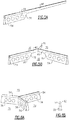
Figure 2 shows other detail of the screen. Theedge portion 52 is shown formed withgroove 59. Normal, or thinner, connectingweb portions 46 extend between theedge 52 and thesupport pads 54. Gas flow holes 56 are shown formed in thesupport pad portion 54. Anothernormal web portion 46 extends beyond thesupport pad portion 54. -
Figure 5B showsnormal web portions 46 meeting at a junction to form a plurality ofspaces 70. -
Figure 5A shows atransition 76 from asupport pad portion 54 to anormal web portion 46.Figure 5B shows an area between twosupport pad portions 54.Figure 6A shows a detail of a support pad. As mentioned above, the support pads are formed of a plurality ofinterconnected webs 54 and there arespaces 70 intermediate these webs. For this reason, the gas flow holes 56 are formed, such that gas can pass through theholes 56, which would otherwise be blocked by the contact betweensupport pad portion 54 and thepedestal 50. - As shown in
Figure 6B , thesupport pad portions 54 have a thicker portion 80 in cross-section which contacts thepedestal 50 andthinner portions 82 which extend outward to maximize gas flow cross-sectional area. - In one embodiment, the support pad portion at its
end 82 extends over less than 20 percent of the over cross-sectional area of theretention screen 57. In embodiments, it may extend over less than 15 percent. In one disclosed embodiment, it extends over approximately 10 percent. -
Figure 7 shows an alternative embodiment where abacking grid 90 is included between theretention screen 57 and thepedestal 50. Thebacking grid 90 has a plurality ofopenings 92 to facilitate gas flow. - The triangular web structure as disclosed above provides maximum retention of the beads, and also tolerance for variable bead diameter. Further, the triangular shape provides higher strength under tension loads to reduce the chance of displacement of the structure. The triangular shape is stronger for a given total mass of webbing and more resistant than other shapes. This provides better resistance to stretching or displacement of the webbing when beads are pressed into the mesh. Further, the ribbon-like shape of the webbing (a height/width ratio is greater than 1.0) provides higher strength for retention while reducing the total pressure drop across the webbing during both process flow and adsorb phase. Further, it reduces out gas flow restrictions during the vacuum desorb phase, and thus overall increases system performance.
-
Figure 8 schematically shows a manufacturing technique which is particularly useful for forming the disclosed embodiments. If the embodiment ofFigure 8 is utilized, thebacking grid 90 could be formed integrally with theretention screen 57. Theretention screen 57 could alternatively be formed on thebacking grid 90 or the two could be separate components. - As shown, an
intermediate retention screen 100 has itsouter edge 52 formed with the O-ring groove 59. A portion of thenormal web 46 has been formed. Anadditive manufacturing tool 102 is shown depositing material at 104. As known, material is typically deposited in layers with these techniques. - In embodiments, the additive manufacturing technique may be depositing metal such as stainless steel, aluminum, titanium or others. Plastics or other materials suitable for additive manufacturing may also be used.
- This application could be summarized as disclosing a retention screen for use in an adsorption canister having outer edges forming a the relatively thick portion and a plurality of support web portions also formed to be relatively thick, and relatively thin connecting web portions connecting said outer edge to said support pad portions. The connecting web portions also connect the support pad portions to each other. The retention screen is generally planar. The thickness of the edge portion and the support pad portions are thicker than the connecting web portions. The thickness of the edge portion and the thickness of the support pad portions may be generally equal, as illustrated. An adsorption system is also disclosed.
- A method of forming a retention screen for an adsorption system is disclosed including the steps of depositing material to form a retention screen having a shape with an outer edge and web portions defining spaces to support an adsorption media.
- Although an embodiment of this invention has been disclosed, a worker of ordinary skill in this art would recognize that certain modifications would come within the scope of this invention. For that reason, the following claims should be studied to determine the true scope and content of this invention.
Claims (15)
- A retention screen (57) for use in an adsorption canister comprising:an outer edge (52) including a seal groove and formed to be relatively thick and a plurality of support pad portions (54) also formed to be relatively thick, and relatively thin connecting web portions (46) connecting said outer edge (52) to said support pad portions (54), and the connecting web portions (46) also connecting said support pad portions (54) to each other, with said retention screen (57) being generally planar and with a thickness of said outer edge (52) and said support pad portions being thicker than a thickness of said connecting web portions (46).
- The retention screen as set forth in claim 1, wherein the thickness of said outer edge (52) and the thickness of said support pad portions (54) being generally equal.
- The retention screen as set forth in claim 1 or 2, wherein said support pad portions (54) and said connecting web portions (46) define a plurality of spaces to support an adsorption media.
- The retention screen as set forth in claim 3, wherein said spaces being sized and designed to capture a minimum bead size of the adsorption media to be retained by said retention screen (57), and/or wherein said spaces are generally triangular.
- The retention screen as set forth in any preceding claim, wherein said support pad portions (54) are formed with a plurality of gas flow holes, and preferably wherein said support pad portion (54) is formed by a plurality of interconnected web portions.
- The retention screen as set forth in any preceding claim, wherein said outer edge portion (52) is formed with vent slots.
- The retention screen as set forth in any preceding claim, wherein said support pad portion is formed by a plurality of interconnected web portions.
- An adsorption system comprising:a canister including a canister housing and opposed covers;an adsorption material space defined between said covers, and retention screens (57) placed between said space, and said each of said covers, and an adsorption media received in said space, and between said retention screens (57); andan outer edge (52) formed integrally with web portions (46), said outer edge (52) having a seal groove, and receiving a seal.
- The adsorption system as set forth in claim 8, wherein said outer edge (52) formed to be relatively thick and a plurality of support pad portions (54) also formed to be relatively thick and relatively thin connecting web portions (46) connecting said outer edge (52) to said support pad portions (54), and the connecting web portions (46) also connecting said support pad portions (54) to each other, with said retention screen (57) being generally planar and with a thickness of said outer edge and said support pad portions being thicker than a thickness of said connecting web portions.
- The adsorption system as set forth in claim 9, wherein the thickness of said outer edge portions (52) and the thickness of said support pad portions (54) being generally equal.
- The adsorption system as set forth in claim 9, wherein a distance between said connecting web portions (46) defining support spaces, and said support spaces being sized and designed to capture a minimum bead size of the adsorption media to be retained by said retention screen (57).
- The adsorption system as set forth in claim 9, wherein said support pad portions (54) are formed with a plurality of gas flow holes, and/or said support pad portion (54) is formed by a plurality of interconnected web portions (46).
- The adsorption system as set forth in claim 9, wherein said outer edge portion is formed with vent slots.
- The adsorption system as set forth in claim 9, wherein support pad portions (54) are in contact with a pedestal on said covers, and preferably wherein there are holes in said support web portion (46) to facilitate flow of gas outwardly of said pedestals.
- A method of forming a retention screen (57) for an adsorption system including the steps of:depositing material to form a retention screen (57) having a shape with an outer edge (52) including a seal groove, and web portions (46) defining spaces to support an adsorption media.
Applications Claiming Priority (1)
| Application Number | Priority Date | Filing Date | Title |
|---|---|---|---|
| US15/295,441 US10105635B2 (en) | 2016-10-17 | 2016-10-17 | One piece media retention screen for adsorption canister |
Publications (2)
| Publication Number | Publication Date |
|---|---|
| EP3308845A1 true EP3308845A1 (en) | 2018-04-18 |
| EP3308845B1 EP3308845B1 (en) | 2020-09-02 |
Family
ID=60382004
Family Applications (1)
| Application Number | Title | Priority Date | Filing Date |
|---|---|---|---|
| EP17196762.3A Active EP3308845B1 (en) | 2016-10-17 | 2017-10-17 | Media retention screen for adsorption canister |
Country Status (2)
| Country | Link |
|---|---|
| US (1) | US10105635B2 (en) |
| EP (1) | EP3308845B1 (en) |
Citations (4)
| Publication number | Priority date | Publication date | Assignee | Title |
|---|---|---|---|---|
| US5718743A (en) * | 1996-02-26 | 1998-02-17 | Multisorb Technologies, Inc. | Desiccant cartridge |
| US6616737B1 (en) * | 1999-10-07 | 2003-09-09 | Stanhope Products Company | Desiccant cartridge retention device |
| US20050198993A1 (en) * | 2004-03-12 | 2005-09-15 | Corrigan Daniel L. | Dessicant cup with integral filter |
| DE102013114772A1 (en) * | 2013-12-23 | 2015-07-09 | Sanner Gmbh | Container with a treatment agent and process for its preparation |
Family Cites Families (12)
| Publication number | Priority date | Publication date | Assignee | Title |
|---|---|---|---|---|
| FR2730423B1 (en) * | 1995-02-15 | 1997-03-21 | Air Liquide | ARRANGEMENT OF A RETAINING GRID OF AN ACTIVE MATERIAL IN A CONTAINER, AND CONTAINER THUS EQUIPPED |
| US5569316A (en) * | 1995-03-01 | 1996-10-29 | Stanhope Products Company | Desiccant container having mount for canister tube and inner wall extension portion |
| US5776228A (en) * | 1997-03-14 | 1998-07-07 | General Motors Corporation | Vapor storage canister with foam screen retainer |
| US6221122B1 (en) * | 1999-02-26 | 2001-04-24 | Donaldson Company, Inc. | Filter element and methods |
| US6178772B1 (en) * | 1999-02-26 | 2001-01-30 | Multisorb Technologies, Inc. | Receiver and filter and adsorbent unit therefor |
| US6334889B1 (en) * | 1999-09-01 | 2002-01-01 | Praxair Technology, Inc. | Bed restraint for an adsorber |
| US6605135B2 (en) * | 2001-09-26 | 2003-08-12 | Air Products And Chemicals, Inc. | Granular bed restraint system |
| JP5322119B2 (en) | 2007-10-08 | 2013-10-23 | ビーエーエスエフ ソシエタス・ヨーロピア | Use of molded bodies with catalytic properties as reactor internal structure |
| US9120037B2 (en) | 2010-01-25 | 2015-09-01 | Spf Innovations, Llc | Stackable planar adsorptive devices |
| US20110271833A1 (en) * | 2010-05-05 | 2011-11-10 | Air Products And Chemicals, Inc. | Adsorbent Bed Support |
| FR3022052B1 (en) | 2014-06-06 | 2016-07-01 | Patrick Herbault | METHOD FOR MODELING AND MANUFACTURING BY 3D PRINTER AN OBJECT COMPRISING A SEMI-HOLLOW BODY COMPRISING A MESH STRUCTURE, SYSTEM THEREFOR |
| MY189561A (en) | 2014-08-27 | 2022-02-16 | Halliburton Energy Services Inc | Methods of fabricating sand control screen assemblies using three-dimensional printing |
-
2016
- 2016-10-17 US US15/295,441 patent/US10105635B2/en active Active
-
2017
- 2017-10-17 EP EP17196762.3A patent/EP3308845B1/en active Active
Patent Citations (4)
| Publication number | Priority date | Publication date | Assignee | Title |
|---|---|---|---|---|
| US5718743A (en) * | 1996-02-26 | 1998-02-17 | Multisorb Technologies, Inc. | Desiccant cartridge |
| US6616737B1 (en) * | 1999-10-07 | 2003-09-09 | Stanhope Products Company | Desiccant cartridge retention device |
| US20050198993A1 (en) * | 2004-03-12 | 2005-09-15 | Corrigan Daniel L. | Dessicant cup with integral filter |
| DE102013114772A1 (en) * | 2013-12-23 | 2015-07-09 | Sanner Gmbh | Container with a treatment agent and process for its preparation |
Also Published As
| Publication number | Publication date |
|---|---|
| US10105635B2 (en) | 2018-10-23 |
| EP3308845B1 (en) | 2020-09-02 |
| US20180104639A1 (en) | 2018-04-19 |
Similar Documents
| Publication | Publication Date | Title |
|---|---|---|
| US8673037B2 (en) | Air filter with balanced seal | |
| JP6103391B2 (en) | Flat gasket and its use | |
| US9370740B2 (en) | Modular stacking filter system | |
| CA2592224A1 (en) | Engineered adsorbent structures for kinetic separation | |
| US20030121845A1 (en) | Fluted filter media for air filter | |
| US11376545B2 (en) | Rapid cycle adsorbent bed | |
| EP2476474A1 (en) | Gas filter assemblies and methods for filtering gases | |
| EP2008004B1 (en) | Gasket and method of forming a seal therewith | |
| CA2632481A1 (en) | Vane-type demister | |
| CN104147861B (en) | Filter assemblies and its manufacturing method for core, biological and chemical air filtering system | |
| WO2012051524A1 (en) | Adsorbent cartridge assembly with end cap | |
| EP1297881A1 (en) | Granular bed restraint system | |
| US20140291242A1 (en) | Membrane module for organophilic pervaporation | |
| US20120285559A1 (en) | Formed seal ring for a liquid gas separating element | |
| EP3308845B1 (en) | Media retention screen for adsorption canister | |
| EP3078405A1 (en) | Filter elements | |
| US6797043B2 (en) | Encapsulated CO2 H2O sorbent | |
| US20150283495A1 (en) | Apparatus for preventing microparticle and dust migration in layered bed purification devices | |
| GB2172814A (en) | Air filter element | |
| JP6407130B2 (en) | Gas-liquid separation element for compressed gas and gas-liquid separation device | |
| EP3980160B1 (en) | Product manifolds for use with portable oxygen concentrators and portable oxygen concentrators including such product manifolds | |
| CN106999839B (en) | Desiccant cartridge | |
| US11383219B2 (en) | Device made of fabric for limiting or preventing the migration of particles between two layers | |
| JP2010094578A (en) | Air filter apparatus | |
| US3756417A (en) | Filter leaf construction and method of making same |
Legal Events
| Date | Code | Title | Description |
|---|---|---|---|
| PUAI | Public reference made under article 153(3) epc to a published international application that has entered the european phase |
Free format text: ORIGINAL CODE: 0009012 |
|
| STAA | Information on the status of an ep patent application or granted ep patent |
Free format text: STATUS: THE APPLICATION HAS BEEN PUBLISHED |
|
| AK | Designated contracting states |
Kind code of ref document: A1 Designated state(s): AL AT BE BG CH CY CZ DE DK EE ES FI FR GB GR HR HU IE IS IT LI LT LU LV MC MK MT NL NO PL PT RO RS SE SI SK SM TR |
|
| AX | Request for extension of the european patent |
Extension state: BA ME |
|
| STAA | Information on the status of an ep patent application or granted ep patent |
Free format text: STATUS: REQUEST FOR EXAMINATION WAS MADE |
|
| 17P | Request for examination filed |
Effective date: 20181018 |
|
| RBV | Designated contracting states (corrected) |
Designated state(s): AL AT BE BG CH CY CZ DE DK EE ES FI FR GB GR HR HU IE IS IT LI LT LU LV MC MK MT NL NO PL PT RO RS SE SI SK SM TR |
|
| GRAP | Despatch of communication of intention to grant a patent |
Free format text: ORIGINAL CODE: EPIDOSNIGR1 |
|
| STAA | Information on the status of an ep patent application or granted ep patent |
Free format text: STATUS: GRANT OF PATENT IS INTENDED |
|
| INTG | Intention to grant announced |
Effective date: 20191119 |
|
| GRAJ | Information related to disapproval of communication of intention to grant by the applicant or resumption of examination proceedings by the epo deleted |
Free format text: ORIGINAL CODE: EPIDOSDIGR1 |
|
| STAA | Information on the status of an ep patent application or granted ep patent |
Free format text: STATUS: REQUEST FOR EXAMINATION WAS MADE |
|
| GRAP | Despatch of communication of intention to grant a patent |
Free format text: ORIGINAL CODE: EPIDOSNIGR1 |
|
| INTC | Intention to grant announced (deleted) | ||
| STAA | Information on the status of an ep patent application or granted ep patent |
Free format text: STATUS: GRANT OF PATENT IS INTENDED |
|
| INTG | Intention to grant announced |
Effective date: 20200416 |
|
| GRAS | Grant fee paid |
Free format text: ORIGINAL CODE: EPIDOSNIGR3 |
|
| GRAA | (expected) grant |
Free format text: ORIGINAL CODE: 0009210 |
|
| STAA | Information on the status of an ep patent application or granted ep patent |
Free format text: STATUS: THE PATENT HAS BEEN GRANTED |
|
| AK | Designated contracting states |
Kind code of ref document: B1 Designated state(s): AL AT BE BG CH CY CZ DE DK EE ES FI FR GB GR HR HU IE IS IT LI LT LU LV MC MK MT NL NO PL PT RO RS SE SI SK SM TR |
|
| REG | Reference to a national code |
Ref country code: GB Ref legal event code: FG4D |
|
| REG | Reference to a national code |
Ref country code: AT Ref legal event code: REF Ref document number: 1308166 Country of ref document: AT Kind code of ref document: T Effective date: 20200915 Ref country code: CH Ref legal event code: EP |
|
| REG | Reference to a national code |
Ref country code: DE Ref legal event code: R096 Ref document number: 602017022699 Country of ref document: DE |
|
| REG | Reference to a national code |
Ref country code: IE Ref legal event code: FG4D |
|
| REG | Reference to a national code |
Ref country code: LT Ref legal event code: MG4D |
|
| PG25 | Lapsed in a contracting state [announced via postgrant information from national office to epo] |
Ref country code: FI Free format text: LAPSE BECAUSE OF FAILURE TO SUBMIT A TRANSLATION OF THE DESCRIPTION OR TO PAY THE FEE WITHIN THE PRESCRIBED TIME-LIMIT Effective date: 20200902 Ref country code: SE Free format text: LAPSE BECAUSE OF FAILURE TO SUBMIT A TRANSLATION OF THE DESCRIPTION OR TO PAY THE FEE WITHIN THE PRESCRIBED TIME-LIMIT Effective date: 20200902 Ref country code: NO Free format text: LAPSE BECAUSE OF FAILURE TO SUBMIT A TRANSLATION OF THE DESCRIPTION OR TO PAY THE FEE WITHIN THE PRESCRIBED TIME-LIMIT Effective date: 20201202 Ref country code: GR Free format text: LAPSE BECAUSE OF FAILURE TO SUBMIT A TRANSLATION OF THE DESCRIPTION OR TO PAY THE FEE WITHIN THE PRESCRIBED TIME-LIMIT Effective date: 20201203 Ref country code: HR Free format text: LAPSE BECAUSE OF FAILURE TO SUBMIT A TRANSLATION OF THE DESCRIPTION OR TO PAY THE FEE WITHIN THE PRESCRIBED TIME-LIMIT Effective date: 20200902 Ref country code: LT Free format text: LAPSE BECAUSE OF FAILURE TO SUBMIT A TRANSLATION OF THE DESCRIPTION OR TO PAY THE FEE WITHIN THE PRESCRIBED TIME-LIMIT Effective date: 20200902 Ref country code: BG Free format text: LAPSE BECAUSE OF FAILURE TO SUBMIT A TRANSLATION OF THE DESCRIPTION OR TO PAY THE FEE WITHIN THE PRESCRIBED TIME-LIMIT Effective date: 20201202 |
|
| REG | Reference to a national code |
Ref country code: NL Ref legal event code: MP Effective date: 20200902 |
|
| REG | Reference to a national code |
Ref country code: AT Ref legal event code: MK05 Ref document number: 1308166 Country of ref document: AT Kind code of ref document: T Effective date: 20200902 |
|
| PG25 | Lapsed in a contracting state [announced via postgrant information from national office to epo] |
Ref country code: PL Free format text: LAPSE BECAUSE OF FAILURE TO SUBMIT A TRANSLATION OF THE DESCRIPTION OR TO PAY THE FEE WITHIN THE PRESCRIBED TIME-LIMIT Effective date: 20200902 Ref country code: LV Free format text: LAPSE BECAUSE OF FAILURE TO SUBMIT A TRANSLATION OF THE DESCRIPTION OR TO PAY THE FEE WITHIN THE PRESCRIBED TIME-LIMIT Effective date: 20200902 Ref country code: RS Free format text: LAPSE BECAUSE OF FAILURE TO SUBMIT A TRANSLATION OF THE DESCRIPTION OR TO PAY THE FEE WITHIN THE PRESCRIBED TIME-LIMIT Effective date: 20200902 |
|
| PG25 | Lapsed in a contracting state [announced via postgrant information from national office to epo] |
Ref country code: PT Free format text: LAPSE BECAUSE OF FAILURE TO SUBMIT A TRANSLATION OF THE DESCRIPTION OR TO PAY THE FEE WITHIN THE PRESCRIBED TIME-LIMIT Effective date: 20210104 Ref country code: RO Free format text: LAPSE BECAUSE OF FAILURE TO SUBMIT A TRANSLATION OF THE DESCRIPTION OR TO PAY THE FEE WITHIN THE PRESCRIBED TIME-LIMIT Effective date: 20200902 Ref country code: CZ Free format text: LAPSE BECAUSE OF FAILURE TO SUBMIT A TRANSLATION OF THE DESCRIPTION OR TO PAY THE FEE WITHIN THE PRESCRIBED TIME-LIMIT Effective date: 20200902 Ref country code: EE Free format text: LAPSE BECAUSE OF FAILURE TO SUBMIT A TRANSLATION OF THE DESCRIPTION OR TO PAY THE FEE WITHIN THE PRESCRIBED TIME-LIMIT Effective date: 20200902 Ref country code: SM Free format text: LAPSE BECAUSE OF FAILURE TO SUBMIT A TRANSLATION OF THE DESCRIPTION OR TO PAY THE FEE WITHIN THE PRESCRIBED TIME-LIMIT Effective date: 20200902 |
|
| PG25 | Lapsed in a contracting state [announced via postgrant information from national office to epo] |
Ref country code: IS Free format text: LAPSE BECAUSE OF FAILURE TO SUBMIT A TRANSLATION OF THE DESCRIPTION OR TO PAY THE FEE WITHIN THE PRESCRIBED TIME-LIMIT Effective date: 20210102 Ref country code: ES Free format text: LAPSE BECAUSE OF FAILURE TO SUBMIT A TRANSLATION OF THE DESCRIPTION OR TO PAY THE FEE WITHIN THE PRESCRIBED TIME-LIMIT Effective date: 20200902 Ref country code: AT Free format text: LAPSE BECAUSE OF FAILURE TO SUBMIT A TRANSLATION OF THE DESCRIPTION OR TO PAY THE FEE WITHIN THE PRESCRIBED TIME-LIMIT Effective date: 20200902 Ref country code: AL Free format text: LAPSE BECAUSE OF FAILURE TO SUBMIT A TRANSLATION OF THE DESCRIPTION OR TO PAY THE FEE WITHIN THE PRESCRIBED TIME-LIMIT Effective date: 20200902 |
|
| REG | Reference to a national code |
Ref country code: CH Ref legal event code: PL |
|
| REG | Reference to a national code |
Ref country code: DE Ref legal event code: R097 Ref document number: 602017022699 Country of ref document: DE |
|
| PG25 | Lapsed in a contracting state [announced via postgrant information from national office to epo] |
Ref country code: MC Free format text: LAPSE BECAUSE OF FAILURE TO SUBMIT A TRANSLATION OF THE DESCRIPTION OR TO PAY THE FEE WITHIN THE PRESCRIBED TIME-LIMIT Effective date: 20200902 Ref country code: LU Free format text: LAPSE BECAUSE OF NON-PAYMENT OF DUE FEES Effective date: 20201017 Ref country code: SK Free format text: LAPSE BECAUSE OF FAILURE TO SUBMIT A TRANSLATION OF THE DESCRIPTION OR TO PAY THE FEE WITHIN THE PRESCRIBED TIME-LIMIT Effective date: 20200902 |
|
| PLBE | No opposition filed within time limit |
Free format text: ORIGINAL CODE: 0009261 |
|
| STAA | Information on the status of an ep patent application or granted ep patent |
Free format text: STATUS: NO OPPOSITION FILED WITHIN TIME LIMIT |
|
| REG | Reference to a national code |
Ref country code: BE Ref legal event code: MM Effective date: 20201031 |
|
| 26N | No opposition filed |
Effective date: 20210603 |
|
| PG25 | Lapsed in a contracting state [announced via postgrant information from national office to epo] |
Ref country code: SI Free format text: LAPSE BECAUSE OF FAILURE TO SUBMIT A TRANSLATION OF THE DESCRIPTION OR TO PAY THE FEE WITHIN THE PRESCRIBED TIME-LIMIT Effective date: 20200902 Ref country code: LI Free format text: LAPSE BECAUSE OF NON-PAYMENT OF DUE FEES Effective date: 20201031 Ref country code: DK Free format text: LAPSE BECAUSE OF FAILURE TO SUBMIT A TRANSLATION OF THE DESCRIPTION OR TO PAY THE FEE WITHIN THE PRESCRIBED TIME-LIMIT Effective date: 20200902 Ref country code: CH Free format text: LAPSE BECAUSE OF NON-PAYMENT OF DUE FEES Effective date: 20201031 Ref country code: BE Free format text: LAPSE BECAUSE OF NON-PAYMENT OF DUE FEES Effective date: 20201031 |
|
| PG25 | Lapsed in a contracting state [announced via postgrant information from national office to epo] |
Ref country code: IT Free format text: LAPSE BECAUSE OF FAILURE TO SUBMIT A TRANSLATION OF THE DESCRIPTION OR TO PAY THE FEE WITHIN THE PRESCRIBED TIME-LIMIT Effective date: 20200902 Ref country code: IE Free format text: LAPSE BECAUSE OF NON-PAYMENT OF DUE FEES Effective date: 20201017 |
|
| PG25 | Lapsed in a contracting state [announced via postgrant information from national office to epo] |
Ref country code: TR Free format text: LAPSE BECAUSE OF FAILURE TO SUBMIT A TRANSLATION OF THE DESCRIPTION OR TO PAY THE FEE WITHIN THE PRESCRIBED TIME-LIMIT Effective date: 20200902 Ref country code: MT Free format text: LAPSE BECAUSE OF FAILURE TO SUBMIT A TRANSLATION OF THE DESCRIPTION OR TO PAY THE FEE WITHIN THE PRESCRIBED TIME-LIMIT Effective date: 20200902 Ref country code: CY Free format text: LAPSE BECAUSE OF FAILURE TO SUBMIT A TRANSLATION OF THE DESCRIPTION OR TO PAY THE FEE WITHIN THE PRESCRIBED TIME-LIMIT Effective date: 20200902 |
|
| PG25 | Lapsed in a contracting state [announced via postgrant information from national office to epo] |
Ref country code: MK Free format text: LAPSE BECAUSE OF FAILURE TO SUBMIT A TRANSLATION OF THE DESCRIPTION OR TO PAY THE FEE WITHIN THE PRESCRIBED TIME-LIMIT Effective date: 20200902 |
|
| P01 | Opt-out of the competence of the unified patent court (upc) registered |
Effective date: 20230522 |
|
| PG25 | Lapsed in a contracting state [announced via postgrant information from national office to epo] |
Ref country code: NL Free format text: LAPSE BECAUSE OF NON-PAYMENT OF DUE FEES Effective date: 20200923 |
|
| PGFP | Annual fee paid to national office [announced via postgrant information from national office to epo] |
Ref country code: GB Payment date: 20250923 Year of fee payment: 9 |
|
| PGFP | Annual fee paid to national office [announced via postgrant information from national office to epo] |
Ref country code: FR Payment date: 20250924 Year of fee payment: 9 |
|
| PGFP | Annual fee paid to national office [announced via postgrant information from national office to epo] |
Ref country code: DE Payment date: 20250923 Year of fee payment: 9 |