EP3308814B1 - Autoinjecteur - Google Patents
Autoinjecteur Download PDFInfo
- Publication number
- EP3308814B1 EP3308814B1 EP17202883.9A EP17202883A EP3308814B1 EP 3308814 B1 EP3308814 B1 EP 3308814B1 EP 17202883 A EP17202883 A EP 17202883A EP 3308814 B1 EP3308814 B1 EP 3308814B1
- Authority
- EP
- European Patent Office
- Prior art keywords
- injection
- autoinjector
- figures
- piston rod
- actuator sleeve
- Prior art date
- Legal status (The legal status is an assumption and is not a legal conclusion. Google has not performed a legal analysis and makes no representation as to the accuracy of the status listed.)
- Active
Links
- 229940090047 auto-injector Drugs 0.000 title claims description 90
- 238000002347 injection Methods 0.000 claims description 172
- 239000007924 injection Substances 0.000 claims description 172
- 230000000694 effects Effects 0.000 claims description 20
- 239000012530 fluid Substances 0.000 claims description 15
- 229940071643 prefilled syringe Drugs 0.000 claims description 3
- 238000006073 displacement reaction Methods 0.000 description 12
- 238000003780 insertion Methods 0.000 description 9
- 230000037431 insertion Effects 0.000 description 9
- 238000004519 manufacturing process Methods 0.000 description 9
- 238000011282 treatment Methods 0.000 description 7
- 230000000903 blocking effect Effects 0.000 description 6
- 230000007246 mechanism Effects 0.000 description 6
- 208000027418 Wounds and injury Diseases 0.000 description 4
- 230000006378 damage Effects 0.000 description 4
- 208000014674 injury Diseases 0.000 description 4
- 239000008188 pellet Substances 0.000 description 4
- 238000003860 storage Methods 0.000 description 4
- 230000001960 triggered effect Effects 0.000 description 4
- 208000031968 Cadaver Diseases 0.000 description 3
- 238000006243 chemical reaction Methods 0.000 description 3
- 230000002093 peripheral effect Effects 0.000 description 3
- 230000000717 retained effect Effects 0.000 description 3
- 230000035939 shock Effects 0.000 description 3
- 240000008042 Zea mays Species 0.000 description 2
- 230000006978 adaptation Effects 0.000 description 2
- 230000008901 benefit Effects 0.000 description 2
- 230000002349 favourable effect Effects 0.000 description 2
- 230000000670 limiting effect Effects 0.000 description 2
- 238000000465 moulding Methods 0.000 description 2
- 230000036961 partial effect Effects 0.000 description 2
- 238000012360 testing method Methods 0.000 description 2
- 230000008719 thickening Effects 0.000 description 2
- 230000000007 visual effect Effects 0.000 description 2
- 206010002199 Anaphylactic shock Diseases 0.000 description 1
- 208000023275 Autoimmune disease Diseases 0.000 description 1
- 208000011231 Crohn disease Diseases 0.000 description 1
- 206010028980 Neoplasm Diseases 0.000 description 1
- 244000046052 Phaseolus vulgaris Species 0.000 description 1
- 235000010627 Phaseolus vulgaris Nutrition 0.000 description 1
- 229910000831 Steel Inorganic materials 0.000 description 1
- 230000009471 action Effects 0.000 description 1
- 208000003455 anaphylaxis Diseases 0.000 description 1
- 208000007502 anemia Diseases 0.000 description 1
- 230000000840 anti-viral effect Effects 0.000 description 1
- 238000013459 approach Methods 0.000 description 1
- 201000011510 cancer Diseases 0.000 description 1
- 210000004027 cell Anatomy 0.000 description 1
- 239000003086 colorant Substances 0.000 description 1
- 238000005520 cutting process Methods 0.000 description 1
- 230000001419 dependent effect Effects 0.000 description 1
- 206010012601 diabetes mellitus Diseases 0.000 description 1
- 238000009792 diffusion process Methods 0.000 description 1
- 238000009826 distribution Methods 0.000 description 1
- 230000005489 elastic deformation Effects 0.000 description 1
- 208000006454 hepatitis Diseases 0.000 description 1
- 231100000283 hepatitis Toxicity 0.000 description 1
- 230000000873 masking effect Effects 0.000 description 1
- 239000002184 metal Substances 0.000 description 1
- 238000000034 method Methods 0.000 description 1
- 238000012986 modification Methods 0.000 description 1
- 230000004048 modification Effects 0.000 description 1
- 201000006417 multiple sclerosis Diseases 0.000 description 1
- 235000010603 pastilles Nutrition 0.000 description 1
- 230000035515 penetration Effects 0.000 description 1
- 230000008569 process Effects 0.000 description 1
- 230000002829 reductive effect Effects 0.000 description 1
- 206010039073 rheumatoid arthritis Diseases 0.000 description 1
- 238000004513 sizing Methods 0.000 description 1
- 239000010959 steel Substances 0.000 description 1
- 230000007704 transition Effects 0.000 description 1
Images


Classifications
-
- A—HUMAN NECESSITIES
- A61—MEDICAL OR VETERINARY SCIENCE; HYGIENE
- A61M—DEVICES FOR INTRODUCING MEDIA INTO, OR ONTO, THE BODY; DEVICES FOR TRANSDUCING BODY MEDIA OR FOR TAKING MEDIA FROM THE BODY; DEVICES FOR PRODUCING OR ENDING SLEEP OR STUPOR
- A61M5/00—Devices for bringing media into the body in a subcutaneous, intra-vascular or intramuscular way; Accessories therefor, e.g. filling or cleaning devices, arm-rests
- A61M5/178—Syringes
- A61M5/20—Automatic syringes, e.g. with automatically actuated piston rod, with automatic needle injection, filling automatically
- A61M5/2033—Spring-loaded one-shot injectors with or without automatic needle insertion
-
- A—HUMAN NECESSITIES
- A61—MEDICAL OR VETERINARY SCIENCE; HYGIENE
- A61M—DEVICES FOR INTRODUCING MEDIA INTO, OR ONTO, THE BODY; DEVICES FOR TRANSDUCING BODY MEDIA OR FOR TAKING MEDIA FROM THE BODY; DEVICES FOR PRODUCING OR ENDING SLEEP OR STUPOR
- A61M5/00—Devices for bringing media into the body in a subcutaneous, intra-vascular or intramuscular way; Accessories therefor, e.g. filling or cleaning devices, arm-rests
- A61M5/178—Syringes
- A61M5/31—Details
- A61M5/315—Pistons; Piston-rods; Guiding, blocking or restricting the movement of the rod or piston; Appliances on the rod for facilitating dosing ; Dosing mechanisms
- A61M5/31565—Administration mechanisms, i.e. constructional features, modes of administering a dose
- A61M5/31566—Means improving security or handling thereof
- A61M5/3157—Means providing feedback signals when administration is completed
-
- A—HUMAN NECESSITIES
- A61—MEDICAL OR VETERINARY SCIENCE; HYGIENE
- A61M—DEVICES FOR INTRODUCING MEDIA INTO, OR ONTO, THE BODY; DEVICES FOR TRANSDUCING BODY MEDIA OR FOR TAKING MEDIA FROM THE BODY; DEVICES FOR PRODUCING OR ENDING SLEEP OR STUPOR
- A61M5/00—Devices for bringing media into the body in a subcutaneous, intra-vascular or intramuscular way; Accessories therefor, e.g. filling or cleaning devices, arm-rests
- A61M5/178—Syringes
- A61M5/20—Automatic syringes, e.g. with automatically actuated piston rod, with automatic needle injection, filling automatically
-
- A—HUMAN NECESSITIES
- A61—MEDICAL OR VETERINARY SCIENCE; HYGIENE
- A61M—DEVICES FOR INTRODUCING MEDIA INTO, OR ONTO, THE BODY; DEVICES FOR TRANSDUCING BODY MEDIA OR FOR TAKING MEDIA FROM THE BODY; DEVICES FOR PRODUCING OR ENDING SLEEP OR STUPOR
- A61M5/00—Devices for bringing media into the body in a subcutaneous, intra-vascular or intramuscular way; Accessories therefor, e.g. filling or cleaning devices, arm-rests
- A61M5/178—Syringes
- A61M5/31—Details
- A61M5/315—Pistons; Piston-rods; Guiding, blocking or restricting the movement of the rod or piston; Appliances on the rod for facilitating dosing ; Dosing mechanisms
- A61M5/31511—Piston or piston-rod constructions, e.g. connection of piston with piston-rod
-
- A—HUMAN NECESSITIES
- A61—MEDICAL OR VETERINARY SCIENCE; HYGIENE
- A61M—DEVICES FOR INTRODUCING MEDIA INTO, OR ONTO, THE BODY; DEVICES FOR TRANSDUCING BODY MEDIA OR FOR TAKING MEDIA FROM THE BODY; DEVICES FOR PRODUCING OR ENDING SLEEP OR STUPOR
- A61M5/00—Devices for bringing media into the body in a subcutaneous, intra-vascular or intramuscular way; Accessories therefor, e.g. filling or cleaning devices, arm-rests
- A61M5/178—Syringes
- A61M5/31—Details
- A61M5/32—Needles; Details of needles pertaining to their connection with syringe or hub; Accessories for bringing the needle into, or holding the needle on, the body; Devices for protection of needles
- A61M5/3205—Apparatus for removing or disposing of used needles or syringes, e.g. containers; Means for protection against accidental injuries from used needles
- A61M5/321—Means for protection against accidental injuries by used needles
- A61M5/3243—Means for protection against accidental injuries by used needles being axially-extensible, e.g. protective sleeves coaxially slidable on the syringe barrel
- A61M5/326—Fully automatic sleeve extension, i.e. in which triggering of the sleeve does not require a deliberate action by the user
-
- A—HUMAN NECESSITIES
- A61—MEDICAL OR VETERINARY SCIENCE; HYGIENE
- A61M—DEVICES FOR INTRODUCING MEDIA INTO, OR ONTO, THE BODY; DEVICES FOR TRANSDUCING BODY MEDIA OR FOR TAKING MEDIA FROM THE BODY; DEVICES FOR PRODUCING OR ENDING SLEEP OR STUPOR
- A61M5/00—Devices for bringing media into the body in a subcutaneous, intra-vascular or intramuscular way; Accessories therefor, e.g. filling or cleaning devices, arm-rests
- A61M5/178—Syringes
- A61M5/20—Automatic syringes, e.g. with automatically actuated piston rod, with automatic needle injection, filling automatically
- A61M2005/2006—Having specific accessories
- A61M2005/2013—Having specific accessories triggering of discharging means by contact of injector with patient body
-
- A—HUMAN NECESSITIES
- A61—MEDICAL OR VETERINARY SCIENCE; HYGIENE
- A61M—DEVICES FOR INTRODUCING MEDIA INTO, OR ONTO, THE BODY; DEVICES FOR TRANSDUCING BODY MEDIA OR FOR TAKING MEDIA FROM THE BODY; DEVICES FOR PRODUCING OR ENDING SLEEP OR STUPOR
- A61M5/00—Devices for bringing media into the body in a subcutaneous, intra-vascular or intramuscular way; Accessories therefor, e.g. filling or cleaning devices, arm-rests
- A61M5/178—Syringes
- A61M5/20—Automatic syringes, e.g. with automatically actuated piston rod, with automatic needle injection, filling automatically
- A61M2005/206—With automatic needle insertion
-
- A—HUMAN NECESSITIES
- A61—MEDICAL OR VETERINARY SCIENCE; HYGIENE
- A61M—DEVICES FOR INTRODUCING MEDIA INTO, OR ONTO, THE BODY; DEVICES FOR TRANSDUCING BODY MEDIA OR FOR TAKING MEDIA FROM THE BODY; DEVICES FOR PRODUCING OR ENDING SLEEP OR STUPOR
- A61M5/00—Devices for bringing media into the body in a subcutaneous, intra-vascular or intramuscular way; Accessories therefor, e.g. filling or cleaning devices, arm-rests
- A61M5/178—Syringes
- A61M5/20—Automatic syringes, e.g. with automatically actuated piston rod, with automatic needle injection, filling automatically
- A61M2005/2073—Automatic syringes, e.g. with automatically actuated piston rod, with automatic needle injection, filling automatically preventing premature release, e.g. by making use of a safety lock
-
- A—HUMAN NECESSITIES
- A61—MEDICAL OR VETERINARY SCIENCE; HYGIENE
- A61M—DEVICES FOR INTRODUCING MEDIA INTO, OR ONTO, THE BODY; DEVICES FOR TRANSDUCING BODY MEDIA OR FOR TAKING MEDIA FROM THE BODY; DEVICES FOR PRODUCING OR ENDING SLEEP OR STUPOR
- A61M5/00—Devices for bringing media into the body in a subcutaneous, intra-vascular or intramuscular way; Accessories therefor, e.g. filling or cleaning devices, arm-rests
- A61M5/178—Syringes
- A61M5/20—Automatic syringes, e.g. with automatically actuated piston rod, with automatic needle injection, filling automatically
- A61M2005/2086—Automatic syringes, e.g. with automatically actuated piston rod, with automatic needle injection, filling automatically having piston damping means, e.g. axially or rotationally acting retarders
-
- A—HUMAN NECESSITIES
- A61—MEDICAL OR VETERINARY SCIENCE; HYGIENE
- A61M—DEVICES FOR INTRODUCING MEDIA INTO, OR ONTO, THE BODY; DEVICES FOR TRANSDUCING BODY MEDIA OR FOR TAKING MEDIA FROM THE BODY; DEVICES FOR PRODUCING OR ENDING SLEEP OR STUPOR
- A61M5/00—Devices for bringing media into the body in a subcutaneous, intra-vascular or intramuscular way; Accessories therefor, e.g. filling or cleaning devices, arm-rests
- A61M5/178—Syringes
- A61M5/31—Details
- A61M2005/3125—Details specific display means, e.g. to indicate dose setting
-
- A—HUMAN NECESSITIES
- A61—MEDICAL OR VETERINARY SCIENCE; HYGIENE
- A61M—DEVICES FOR INTRODUCING MEDIA INTO, OR ONTO, THE BODY; DEVICES FOR TRANSDUCING BODY MEDIA OR FOR TAKING MEDIA FROM THE BODY; DEVICES FOR PRODUCING OR ENDING SLEEP OR STUPOR
- A61M5/00—Devices for bringing media into the body in a subcutaneous, intra-vascular or intramuscular way; Accessories therefor, e.g. filling or cleaning devices, arm-rests
- A61M5/178—Syringes
- A61M5/31—Details
- A61M5/315—Pistons; Piston-rods; Guiding, blocking or restricting the movement of the rod or piston; Appliances on the rod for facilitating dosing ; Dosing mechanisms
- A61M5/31511—Piston or piston-rod constructions, e.g. connection of piston with piston-rod
- A61M2005/31518—Piston or piston-rod constructions, e.g. connection of piston with piston-rod designed to reduce the overall size of an injection device, e.g. using flexible or pivotally connected chain-like rod members
-
- A—HUMAN NECESSITIES
- A61—MEDICAL OR VETERINARY SCIENCE; HYGIENE
- A61M—DEVICES FOR INTRODUCING MEDIA INTO, OR ONTO, THE BODY; DEVICES FOR TRANSDUCING BODY MEDIA OR FOR TAKING MEDIA FROM THE BODY; DEVICES FOR PRODUCING OR ENDING SLEEP OR STUPOR
- A61M2205/00—General characteristics of the apparatus
- A61M2205/33—Controlling, regulating or measuring
- A61M2205/3327—Measuring
-
- A—HUMAN NECESSITIES
- A61—MEDICAL OR VETERINARY SCIENCE; HYGIENE
- A61M—DEVICES FOR INTRODUCING MEDIA INTO, OR ONTO, THE BODY; DEVICES FOR TRANSDUCING BODY MEDIA OR FOR TAKING MEDIA FROM THE BODY; DEVICES FOR PRODUCING OR ENDING SLEEP OR STUPOR
- A61M2205/00—General characteristics of the apparatus
- A61M2205/33—Controlling, regulating or measuring
- A61M2205/3368—Temperature
-
- A—HUMAN NECESSITIES
- A61—MEDICAL OR VETERINARY SCIENCE; HYGIENE
- A61M—DEVICES FOR INTRODUCING MEDIA INTO, OR ONTO, THE BODY; DEVICES FOR TRANSDUCING BODY MEDIA OR FOR TAKING MEDIA FROM THE BODY; DEVICES FOR PRODUCING OR ENDING SLEEP OR STUPOR
- A61M2205/00—General characteristics of the apparatus
- A61M2205/58—Means for facilitating use, e.g. by people with impaired vision
- A61M2205/581—Means for facilitating use, e.g. by people with impaired vision by audible feedback
-
- A—HUMAN NECESSITIES
- A61—MEDICAL OR VETERINARY SCIENCE; HYGIENE
- A61M—DEVICES FOR INTRODUCING MEDIA INTO, OR ONTO, THE BODY; DEVICES FOR TRANSDUCING BODY MEDIA OR FOR TAKING MEDIA FROM THE BODY; DEVICES FOR PRODUCING OR ENDING SLEEP OR STUPOR
- A61M2205/00—General characteristics of the apparatus
- A61M2205/58—Means for facilitating use, e.g. by people with impaired vision
- A61M2205/582—Means for facilitating use, e.g. by people with impaired vision by tactile feedback
-
- A—HUMAN NECESSITIES
- A61—MEDICAL OR VETERINARY SCIENCE; HYGIENE
- A61M—DEVICES FOR INTRODUCING MEDIA INTO, OR ONTO, THE BODY; DEVICES FOR TRANSDUCING BODY MEDIA OR FOR TAKING MEDIA FROM THE BODY; DEVICES FOR PRODUCING OR ENDING SLEEP OR STUPOR
- A61M2205/00—General characteristics of the apparatus
- A61M2205/58—Means for facilitating use, e.g. by people with impaired vision
- A61M2205/583—Means for facilitating use, e.g. by people with impaired vision by visual feedback
- A61M2205/584—Means for facilitating use, e.g. by people with impaired vision by visual feedback having a color code
-
- A—HUMAN NECESSITIES
- A61—MEDICAL OR VETERINARY SCIENCE; HYGIENE
- A61M—DEVICES FOR INTRODUCING MEDIA INTO, OR ONTO, THE BODY; DEVICES FOR TRANSDUCING BODY MEDIA OR FOR TAKING MEDIA FROM THE BODY; DEVICES FOR PRODUCING OR ENDING SLEEP OR STUPOR
- A61M5/00—Devices for bringing media into the body in a subcutaneous, intra-vascular or intramuscular way; Accessories therefor, e.g. filling or cleaning devices, arm-rests
- A61M5/178—Syringes
- A61M5/31—Details
- A61M5/32—Needles; Details of needles pertaining to their connection with syringe or hub; Accessories for bringing the needle into, or holding the needle on, the body; Devices for protection of needles
- A61M5/3202—Devices for protection of the needle before use, e.g. caps
- A61M5/3204—Needle cap remover, i.e. devices to dislodge protection cover from needle or needle hub, e.g. deshielding devices
-
- A—HUMAN NECESSITIES
- A61—MEDICAL OR VETERINARY SCIENCE; HYGIENE
- A61M—DEVICES FOR INTRODUCING MEDIA INTO, OR ONTO, THE BODY; DEVICES FOR TRANSDUCING BODY MEDIA OR FOR TAKING MEDIA FROM THE BODY; DEVICES FOR PRODUCING OR ENDING SLEEP OR STUPOR
- A61M5/00—Devices for bringing media into the body in a subcutaneous, intra-vascular or intramuscular way; Accessories therefor, e.g. filling or cleaning devices, arm-rests
- A61M5/178—Syringes
- A61M5/31—Details
- A61M5/32—Needles; Details of needles pertaining to their connection with syringe or hub; Accessories for bringing the needle into, or holding the needle on, the body; Devices for protection of needles
- A61M5/3205—Apparatus for removing or disposing of used needles or syringes, e.g. containers; Means for protection against accidental injuries from used needles
- A61M5/321—Means for protection against accidental injuries by used needles
- A61M5/3243—Means for protection against accidental injuries by used needles being axially-extensible, e.g. protective sleeves coaxially slidable on the syringe barrel
- A61M5/3271—Means for protection against accidental injuries by used needles being axially-extensible, e.g. protective sleeves coaxially slidable on the syringe barrel with guiding tracks for controlled sliding of needle protective sleeve from needle exposing to needle covering position
- A61M5/3272—Means for protection against accidental injuries by used needles being axially-extensible, e.g. protective sleeves coaxially slidable on the syringe barrel with guiding tracks for controlled sliding of needle protective sleeve from needle exposing to needle covering position having projections following labyrinth paths
Definitions
- the present invention relates to an autoinjector.
- Autoinjectors are well known in the state of the art. The main purpose of these devices is to achieve automatic injection of the contents of a syringe inside the body of a patient. Various systems exist to make the penetration of the needle into the patient's body and the injection of the fluid product contained in the syringe automatic. Autoinjectors are relatively complex devices which must meet a certain number of stress requirements to be reliable. The robustness of the device, its maneuverability, and its ease of use for the user are also important elements. Furthermore, since most of these autoinjectors are disposable, the cost of manufacture and assembly is also a factor to be taken into account.
- the devices must include reliable locking means.
- the device when a user wishes to use the autoinjector and unlocks the device, for example by removing the cover, the device must not be triggered inadvertently but only when the user really wishes it, c 'that is to say when he applies it against the part of the body in which he wants to perform the injection.
- the autoinjector does not trigger on its own. It is therefore important to provide a reliable trip lock.
- the time required to carry out this injection can be quite long, being able in particular to exceed several seconds. It is then very important that the user does not remove the device from his body before the injection is complete. It is therefore desirable for the device to include means making it possible to reliably indicate to the user that the injection is finished.
- the autoinjector in order to avoid any risk of injury after use of the device, the autoinjector must include a needle safety device which prevents the needle from remaining visible after use of the device.
- This safety device must obviously also be reliable and not release too easily. It must also be functional even if the user operates the autoinjector incorrectly, for example if he withdraws it too early from his body, before the end of the injection.
- Another important aspect with autoinjectors is to allow the product to diffuse from the injection site for a few seconds after said injection. If the user removes the autoinjector immediately after the end of the injection, part of the product may come out of the user's body which reduces the effectiveness of the treatment. It is therefore desirable to provide for the user to maintain the autoinjector against his body for a few seconds after the end of the injection.
- This aspect is generally solved by existing autoinjectors by the user manual which asks the user to count in his head a certain number of seconds before removing the device. This is not reliable and therefore unsatisfactory, because the system then depends on the user himself, who in certain cases can be disturbed or weakened by the injection action that he has just performed.
- the object of the present invention is to provide an autoinjector which does not reproduce the aforementioned drawbacks, and which makes it possible to meet the various requirements and significant constraints for safe and reliable use of the autoinjector.
- Another object of the present invention is to provide an autoinjector which is reliable in use, which makes it possible to guarantee the distribution of all of the fluid product to the desired location, which allows the user to determine when to withdraw or when. it can remove the autoinjector from its body after use, which is safe and prevents any risk of injury, and which is simple and inexpensive to manufacture and assemble.
- the autoinjector will be described below with reference to various variants of two advantageous embodiments thereof.
- a first embodiment is shown in the figures 1 to 46 and a second embodiment is shown in the figures 47 to 74c .
- these autoinjectors which are complex devices, include several modules to perform several functions. These various modules can be used separately and independently of each other, without necessarily being combined with the other modules, and could in particular be used in autoinjectors of different shape from that shown in the drawings.
- the autoinjector comprises a central body 1, a control ring 2, a stitching spring 3, a control sleeve 4, a piston rod 5, a support pad 6, three locking elements 7, here in the form of balls, an injection spring 8, a control slide 9, a lower body 10, an actuator sleeve 11, a spring 12 of the actuator sleeve, a reservoir housing 13, a cover 14, an upper body 15, a plurality of planetary 16, a plurality of planet wheels 17, a delay spring 18, a trigger 19, a locking finger 20, a wire 21, an outer shell 22 and a ring of blocking 23. All these elements form part of the embodiment described, but all are not essential for the operation of the autoinjector, as will be more precisely described below.
- the cover 14 makes it possible in particular to lock the autoinjector during transport and storage. As long as this cover is assembled on the lower body 10, it prevents any actuation of the actuator sleeve 11, and therefore any triggering of the autoinjector.
- a reservoir A can be inserted into said autoinjector.
- This reservoir contains fluid, and comprises a piston and a needle.
- the piston is adapted to move in said reservoir to inject the fluid product through said needle.
- a syringe A which can be of any type. More generally, it is understood that the term “syringe” in the present description encompasses any type of reservoir associated with a needle.
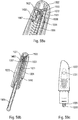
- syringe A is a pre-filled syringe. It advantageously comprises a needle cap B which protects and isolates the needle before use of the autoinjector.
- this needle cap B is automatically removed when the cover 14 is withdrawn from the lower body 10.
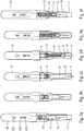
- the figures 2a to 2f illustrate the sequences of the use of the autoinjector of the figure 1 .
- the user wants to use the autoinjector, he takes the device, for example at the level of the outer shell 22 and he presses the actuator sleeve 11, which in a first projected position projects out of the lower body 10, against the part of the body where he wants to perform the injection.
- the actuator sleeve 11 On the figure 2b , it can be seen that the pressure exerted by the user on the actuator sleeve 11 causes the latter to slide towards the inside of the lower body 10, with the effect of compressing the spring of the actuator sleeve 12.
- the actuator sleeve 11 When the actuator sleeve 11 reaches its actuation position, which is its end position inside the lower body 10, it causes the triggering of the stitch lock and therefore the movement of the control sleeve 4 in the lower body. 10 under the effect of the stitching spring 3, with the consequence of a displacement of the syringe A in the lower body 10 and therefore the insertion of the needle of the syringe into the body of the user, as visible on the figure figure 2c .
- the autoinjector provides for retraction of the syringe A.
- the needle is therefore retracted out of the user's body towards the inside the autoinjector, as shown in figure 2e .
- the actuator sleeve 11 is again moved out of the lower body 10 to a second projected position, under the effect of the spring 12 of the actuator sleeve, with a locking of said actuator sleeve 11, which guarantees absolute safety for user and avoids any risk of injury with the needle after using the device.
- first and second projected positions of the actuator sleeve which, in the example shown, are different positions, could possibly be identical.
- Said actuator sleeve 11 comprises a flexible tab 110 which has double flexibility. On the one hand, it is radially flexible, that is to say that it deforms towards the inside of the actuator sleeve 11. It is then also flexible laterally, that is to say that it deforms in the direction. peripheral of the actuator sleeve 11.
- An actuator sleeve 11 provided with such a flexible tab is simple to mold, which is favorable from the point of view of manufacturing costs.
- the flexible tab 110 advantageously comprises a rod portion 111 which is flexible and which ends in a head portion 112. Said flexible tab 110 is adapted to deform on the one hand radially and on the other hand laterally relative to said central body.
- said flexible tab 110 is radially deformed when said sleeve actuator 11 moves from its first projected position, before actuation, to its actuation position, and said flexible tab is deformed laterally when said actuator sleeve 11 moves from its actuation position to its second projected position, at the end of use. It is this variant which is shown in the figures.
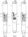
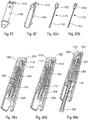
- the figures 3a, 3b and 3c are three partial schematic views in perspective which show the end positions of the actuator sleeve 11, namely on the figure 3a the first projected position at rest before actuation, on the figure 3b the actuation position in which the actuator sleeve 11 has been inserted as far as possible inside the lower body 10, and on the figure 3c the second projected position with the actuator sleeve 11 locked relative to the lower body 10, at the end of use.
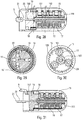
- the central body 1 has cutouts forming grooves and shoulders which are detailed below.
- the central body 1 is fixed to the lower body 10 and the actuator sleeve 11 is slidably disposed inside said lower body 10.
- the central body 1 comprises a first groove 101, substantially axial, and an opening 103, separated from said first groove 101 but disposed in the axial extension of said first groove 101. Said central body 1 also comprising a radial cam 102 disposed between said first groove 101 and said opening 103. As visible in particular on the figures 6 and 7 , said radial cam 102 may be formed by an inclined radial thickening of the wall of the central body 1, said thickening being formed at the axial end of the first groove 101.
- Said radial cam 102 cooperating with said head 112 of said flexible tab 110 to radially deform said flexible tab 110 and thus allow said head 112 to pass from said first groove 10 to said opening 103 during movement of the actuator sleeve 11 towards its actuation position.
- Said central body 1 comprises a final reception zone 105 offset axially and laterally with respect to said opening 103.
- this final reception zone 105 is arranged axially. approximately at the level of said first groove 101.
- the opening 103 is connected to said final receiving zone 105 by a laterally inclined groove 104.
- An axial shoulder 106 is provided between said final receiving zone 105 and said inclined groove 104.
- said actuator sleeve 11 When said actuator sleeve 11 reaches its second projected position, after use, said head 112 engages under said axial shoulder 106, thus locking said actuator sleeve 11 relative to said central body 1 and relative to lower body 10. From this locked position, said actuator sleeve does not can no longer be moved in the direction of its actuating position, due to the stop formed between the head 112 of the p reach flexible 110 and the axial shoulder 106.
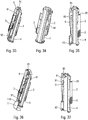
- the figures 4 to 8 represent the starting position, that is to say the moment when the user will start to use the autoinjector. It can be seen in these figures that the head 112 is disposed in said axial groove 101 of the central body 1. When the actuator sleeve 11 slides towards the inside of the lower body 10, said head 112 of the flexible tab 110 will slide inside. of said groove 101 of the central body. When the head 112 reaches the axial end of the first groove 101, said radial cam 102 will cooperate with said head 112. This radial cam 102 will therefore deform the flexible tab 110, and in particular its rod portion 111, radially towards the interior towards its longitudinal central axis.
- the figures 9 to 12 illustrate the position in which the flexible tab 110 is radially deformed. As visible in particular on the figure 11 , after this radial deformation, the head 112 of the flexible tab 110 will continue to move axially over a further distance until it reaches said opening 103. The actuator sleeve 11 then reaches its actuation position, as shown in FIG. figure 13 .
- the flexible tab 110 resiliently returns to its radially undeformed position.
- the head 112 of the flexible tab 110 then enters inside said opening 103 as visible on the figure 14 .
- the actuator sleeve 11 When the actuator sleeve 11 reaches its actuation position, that is to say in the position of the figures 13 to 16 , the spring 12 of the actuator sleeve has been compressed and the stitching lock is triggered by said actuator sleeve 11, as will be more fully described later, which causes the movement of the syringe A inside the lower body 10 and therefore pricking the needle into the user's body.
- the actuator sleeve 11 does not move relative to the lower body 10, since the user maintains his pressure on the part of the body in which he performs the injection.
- the spring 12 of the actuator sleeve 11 will urge said actuator sleeve 11 back from its actuation position to its second projected position, as shown. on the figure 3c .
- the head 112 of the flexible tab 110 will cooperate with the inclined groove 104 as visible on the figures. figures 17 and 18 . This will cause an elastic deformation of the flexible tab 110, and in particular of its rod portion 111, at the as the actuator sleeve 11 will slide axially, the head 112 sliding in said inclined groove 104 laterally deforming said flexible tab 110 as clearly visible on the figure figure 17 .
- This inclined groove 104 ends in a final reception zone 105 provided with an axial shoulder 106.
- the head 112 of the flexible tab 110 will enter this final reception zone 105 and the upper edge 114 of the head 112 will cooperate with the axial shoulder 106, which will block the actuator sleeve 11 with respect to the lower body 10.
- the actuator sleeve 11 can then no longer slide axially towards the inside of the lower body 10, and the safety device is then in the locked end position.
- the needle is completely protected after use and the user can no longer use the autoinjector or injure himself with the needle.
- the actuator sleeve described above is particularly efficient and reliable, while being robust and easy and therefore inexpensive to mold.
- the figures 32 to 46 more particularly describe the device for moving the syringe in the lower body 10.
- This moving device provides on the one hand the pricking, that is to say the insertion of the needle into the body of the user, and d on the other hand, the retraction of the needle after injection.
- the syringe A is moved axially in said lower body 10 in order to insert the needle into the body of the user.
- the syringe A is again moved in the other direction inside the lower body 10, to be retracted and thus automatically exit the needle from the user's body. In this way when the user removes the autoinjector from his body, the needle is no longer protruding but on the contrary retracted inside said autoinjector.
- a control ring 2 which cooperates with the control sleeve 4, with the control slide 9 as well as with the actuator sleeve 11. Furthermore, the trigger 19 intervenes to effect the retraction of the syringe inside the body as will be explained below.
- the figures 33 to 35 illustrate the starting position before the syringe is moved for pricking. It can be seen that the control ring 2 is rotated by the stitching spring 3, which here is a spring acting in torsion. Such a torsion spring makes it possible to carry out a painless stitching.
- the control ring 2 comprises three inclined profiles 24, 25, 26 similar to ramps, the functions of which will be explained below.
- the control ring 2 comprises a first inclined internal profile 24, such as a ramp, which will cooperate with a projection 44 of the control sleeve 4.
- a first inclined internal profile 24 such as a ramp
- This control sleeve 4 cooperates with the syringe housing 13 which receives the syringe, and thus a movement of the control sleeve moves the syringe A in the lower body 10 to carry out the puncture of the needle.
- the figure 39 illustrates the position in which the needle is fully inserted, with the first inclined profile 24 which cooperates with the projection 44 of the control sleeve 4.
- the projection 91 of the control slide is also in contact with an external inclined profile 25 of the ring 2, such that an external ramp, which will cause an additional axial displacement of said control slide 9 with respect to the actuator sleeve 11.
- This will move the control slide 9 in the same direction as the actuator sleeve 11 during stitching. Therefore, the projection 92 of the control slider 9 comes close to an upper projection 119 of the actuator sleeve 11, and the projection 95 of the control slider 9 comes close to a projection 191 of the trigger 19, as visible on the figure. figure 44 .
- the first internal inclined ramp 24 which cooperates with the projection 44 of the control sleeve 4 advantageously comprises a flat 241, that is to say a non-inclined portion, visible on the figure 41 .
- This flat 241 has a very important function since it guarantees that the start of the injection will only occur after the complete end of the insertion of the needle into the body of the user. While for many autoinjectors it is necessary to start the injection a little before the needle reaches its end point of insertion, for reasons of manufacturing tolerance, the flat 241 on the ramp 24 makes it possible to avoid this. phenomenon.
- the ring 2 has already completely displaced the control sleeve 4 axially and therefore has achieved the total insertion of the needle of the syringe into the body of the user, it is necessary for the ring 2 to turn further. on the arc of a circle formed by said flat, for example over approximately 30 °, to trigger the injection lock.
- the locking ring 23 of the injection lock is only moved out of its locking position after the additional rotation of the ring 2 on the arc of a circle formed by said flat 241.
- a second internal inclined profile 26, such as a ramp, of the control ring 2 will cooperate with a projection 235 of the locking ring 23 of the injection lock. and moving the latter out of its blocking position to release the injection, when the control ring 2 reaches the end of its additional rotation.
- the control ring 2 comprises three second internal inclined profiles 26 arranged at 120 ° to each other
- the locking ring 23 comprises three projections 235 also arranged at 120 ° to each other, a respective projection 235 cooperating with a respective second internal inclined profile 26.
- the piston rod 5 will release the rotation of a trigger 19, possibly with a certain delay if a delay device is used. From the moment when the trigger 19 has performed a predefined rotation, a projection 191 of the trigger 19 will cooperate with the upper shoulder 95 of the control slide 9, and this control slide 9 will be moved axially downward on the figure 44 , which will release the rotation of the control ring 2 as described above.
- the figures 45 and 46 illustrate the retraction of the needle with the rotation of the ring 2 which will bring the projection 44 of the control sleeve facing an internal groove of the ring 2, which will cause, under the effect of the spring, the axial displacement in return of the control sleeve 4 inside the control ring 2 and therefore the retraction of the syringe and the needle.
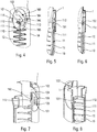
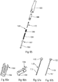
- the figures 19 to 26 schematically illustrate an advantageous injection lock.
- the autoinjector comprises injection means, comprising in particular the piston rod 5, the injection spring 8 and the locking ring 23, these injection means being locked in a position loaded by said injection lock. Unlocking said injection lock then causes actuation of said injection means and therefore injection of the fluid product through the needle.
- said injection lock comprises a control sleeve 4 disposed in said central body 1, said control sleeve 4 containing said piston rod 5 and said injection spring 8, said piston rod 5 comprising a radial recess 50 receiving at at least one locking element 7 movable between a locking position and an unlocking position.
- Said at least one locking element 7 is preferably of substantially spherical shape.
- Said balls 7 are urged radially outwards by said piston rod 5 and are retained in the locking position by a locking member, which in this embodiment is formed by a locking ring 23.
- This locking ring 23 is axially displaceable relative to said piston rod 5 between a locking position, in which it maintains the locking elements 1007 in the locking position, and an unlocking position, in which said locking elements 1007 are released to thereby unlock said injection lock, allowing said injection spring to move said piston rod 5 towards its injection position.
- the figure 20 shows the injection lock in the locked position.
- the injection spring 8 cooperates on the one hand with the piston rod 5 and on the other hand with a support disc 6.
- This support disc 6 is formed by a ring arranged around said piston rod 5.
- the piston rod 5 comprises a peripheral recess 50, advantageously provided with an inclined surface 51, formed by a narrowing of the diameter of said piston rod 5.
- This piston rod 5 is disposed inside the control body 4 and is capable of be moved axially to the left on the figure 20 to push the plunger of syringe A inside the syringe and dispense the fluid product contained in said syringe through the needle.
- the balls 7 are arranged in said recess 50 formed in the piston rod 5 and therefore cooperates with on the one hand the inclined wall 51 of the piston rod 5 and on the other hand with the upper surface 61 of said support pad 6 .
- the inclined surface 51 of the piston rod is in contact with the balls 7 so that under the effect of the compressed spring 8, said inclined surface 51 exerts a reaction force F1 on the balls 7, this force F1 not being exactly axial but directed slightly outward, thus biasing the balls 7 radially outward from the locking position of the figure 20 .
- the locking ring 23 is provided radially on the outside of the balls 7 in order to radially block said balls in the locking position.
- the balls can be placed in housings of the control sleeve 4, the locking ring 23 comprising projections 231, one for each ball 7, which come into contact with the balls 7 to prevent them from being displaced radially outward.
- the pad 6 transmits the force F3 of the spring 8 to the balls 7, and the locking ring 23 exerts a reaction force F2 on the balls 7 to prevent a radial displacement of the latter.
- the balls 7 which support all the forces exerted on the lock in the blocking position, with a three-point balance under the effect of the forces F1, F2 and F3.
- Such a lock is particularly stable and robust, and makes it possible in particular to withstand drops tests. These tests simulate the fact of dropping the autoinjector on the ground after having removed the cover 14, the objective being to avoid triggering the injection lock during this fall. In particular, no force is exerted on the structural parts of the autoinjector, such as the central body 1 or the lower body 10. This lock thus makes it possible to avoid a risk of untimely dismantling of the device during transport or storage. handling.
- the balls 7 could be replaced by non-spherical elements but of a more complex rounded shape, for example in the shape of a cylinder or of a bean, in order to further improve the stability of the lock.
- these non-spherical mobile elements could be made of metal, for example by cutting with a steel wire.
- the locking ring 23 is moved according to the arrow E1 on the figure 21 . This has the effect of releasing the balls 7 from their blocking position, the latter then being displaced radially outwardly according to the arrow E2. As a variant, the locking ring 23 could also be moved in rotation to a position where it releases the balls. The support pad 6 then comes into abutment against an internal edge of the control sleeve 4 as represented by the arrow E3 on the figure 21 .
- the piston rod 5 is no longer retained by the balls 7 and it is therefore displaced axially, that is to say to the left on the figure 21 , to perform the injection of the product.
- the balls 7 can no longer return to the blocking position, prevented by the pellet 6, as visible on the figure 21 .
- the figures 23 to 26 illustrate with slightly different views the two locking and unlocking positions of the injection lock as described above with reference to figures 20 and 21 .
- the injection lock shown on figures 19 to 26 enables a large force exerted by a compressed spring, in this case the injection spring 8, to be unlocked, by exerting a relatively weak and easily controllable force on the locking ring 23.
- the force necessary to move said locking ring. locking 23 in the unlocked position may represent only 10%, or even only 5%, of the force exerted by the injection spring 8. This represents a very high efficiency which guarantees easy and reliable actuation of the device.
- a trigger 19 is actuated to retract the syringe and therefore the needle.
- a locking finger 20 extends through the trigger 19 and into the central channel 151 of the upper body 15.
- This rotation is blocked by the locking finger 20, advantageously of oblong shape, which is adapted to rotate together with said trigger 19, but which is blocked in rotation by said central channel 151 of the upper body 15.
- the piston rod 5 moves axially, that is to say to the left on the figure 28 . As it moves, it will pull on the wire 21 which will therefore extend out of the channel 151.
- the rotation of the trigger 19 is blocked.
- the trigger 19 comprises an inclined external ramp 190 which may include a projection 191 on one side.
- this projection 191 will cooperate with the control slide 9, this which will move the latter axially and thus trigger the retraction of the needle, as has been described above.
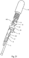
- the figures 27 to 31 illustrate an advantageous delay device.
- this delay device which is optional in an autoinjector, is to shift the retraction of syringe A and therefore of the needle out of the user's body in time after the end of the injection of the fluid product to inside said body. This allows in particular a diffusion for a few seconds of the product after its injection.
- Such a retarder also provides a benefit for the user, who no longer has to count, for example up to 10, after his injection, the time taken for this counting possibly being very variable from one user to another. With a retarder, the sequence of use of an autoinjector is facilitated.
- the figure 27 illustrates a schematic exploded view of this delay device.
- This comprises the upper body 15, several planetary 16 with several satellites 17, the retarder spring 18, the trigger 19, the locking finger 20, the wire 21 and the piston rod 5. It is this piston rod 5 which will actuate the delay device when it reaches the end of the injection stroke with all of the product that has been injected.
- the figure 28 shows the delay device before it is activated. It can be seen that the actuating rod 5 is connected to the locking finger 20 via the wire 21. In this position, the wire 21 and the locking finger 20 extend inside a central channel 151. of the upper body 15 and in the trigger 19.
- the upper body 15 has a gear 155 on its lateral internal surface, as clearly visible on the figure. figure 30 . This internal gear 155 of the upper body 15 cooperates with a plurality of planet wheels 17 which are assembled on planets 16. In the example shown in FIG. figure 28 , there are several planets stacked axially on top of each other.
- the sun gears 16 comprise a disc-shaped plate on which are formed on one side of the planet support rods 161 which each rotatably receive a planet gear 17.
- the delay device uses the principle of epicyclic gears. Each stage of this device makes it possible to multiply and / or slow down the rotations of the previous stage.
- the trigger 19 cooperates with a first sun gear 16, the rods 161 of which extend inside said trigger 19.
- the gear 162 of this first sun gear 16 then cooperates with the satellites of a second adjacent sun gear, which cooperate with the lateral gear 155 of the upper body 15, thus reducing the rotation of the first sun gear and therefore of the trigger, and therefore slowing down this rotation.
- Each additional stage of the epicyclic train forming the retarder will further reduce these rotations, and therefore further slow down the rotation of the trigger 19.
- Friction braking can also be provided, for example between the planet wheels 17 and the internal gear 155 of the upper body 15.
- the delay device therefore makes it possible to shift by a predetermined time the moment when said trigger will actuate the retraction of the needle, from the moment when the injection phase has ended.
- the outer shell 22 comprises several indicators which make it possible to inform the user of the progress of the stitching, injection and retraction sequences. If a delay device is used, it is also possible to provide for a display of said delay.
- the outer shell 22 may include several viewing windows, in this case three windows 221, 222, 223, which make it possible to view mobile elements during the different actuation phases, these elements comprising indicators, typically colors.
- control slide 9 which at rest is in a first position relative to the central body 1, moves axially towards a second position during the movement of the actuator sleeve 11. It then remains in this second position throughout phase d. injection, and returns to its first position when the needle is retracted. It is only when the actuator sleeve returns to its second projected position, that the control slide reaches this first position.
- This control slider 9 may include one or more color indicators, for example a red horn zone visible on the figure 1 . This slide can therefore be used to indicate on the one hand the projected position of the actuator sleeve 11 (first position) and on the other hand the stitching and injection phase (second position).
- the trigger 19, which triggers the retraction of the needle at the end of the injection can also include an indicator, for example a red zone, which is displayed when said trigger has achieved its predefined rotation and thus actuated the retraction of the needle. needle.
- an indicator for example a red zone
- the first viewing window 221 can be the end of injection window, that is to say that when a predefined color, for example red, appears in the window 221, the injection is finished and the syringe has been retracted.
- the user therefore knows that when this first viewing window is red, he can safely remove the autoinjector from his body.
- This indication can for example be provided by the trigger 19.
- the second viewing window 222 may be that of the stitching and injection phases, which changes to red during the start of the stitching phase to the end of the injection phase. This is to prevent the user from removing the autoinjector from his body during these phases, which can last several seconds. This indication can be provided by the actuator slide 9.
- the third viewing window 223 may be that of the actuator sleeve 11, with red displayed when the actuator sleeve 11 is in a position projected out of the lower body. This third viewing window 223 is therefore red before actuation, then again after use, when the actuator sleeve 11 is locked in the safety position.
- This indication can be supplied by the control slide 9.
- the red zone of the actuator slide 9 passes from the third viewing window 223, before actuation ( figure 2a ) to the second viewing window 222 ( figure 2c ) when the actuator sleeve is in the actuation position where it triggers the stitching phase. During this transition, said red zone is not visible, being located between said windows 223 and 222 ( figure 2b ).
- the control slide remains in its second position ( figure 2c & figure 2d ).
- the control slider 9 is again moved axially towards its first position by the trigger 19, to actuate the retraction of the needle, the red zone passes between the second window 222 to the third window 223, again being invisible ( figure 2e ), to finally reappear in the third window 223 when the actuator sleeve is locked in the second projected position ( figure 2f ).
- the combination of red in the first and third viewing windows 221 and 223 guarantees the end of the process of using the autoinjector, with the needle retracted and the actuator sleeve 11 locked, which guarantees optimum safety. .
- said outer shell 22 may include any number of viewing windows, of any shape and size, and which could be positioned differently from the variant shown. in the figures.
- the same window can in particular display several different functions.
- Other variants are of course also possible.
- This outer shell 22 can also include one or more buttons for stitching and / or retracting the needle, if the autoinjector provides such buttons for carrying out the stitching and / or retraction of the needle.
- the outer shell 22 could also include a temperature indicator for the product to be injected. Indeed, many products to be injected are stored at 8 ° and it is often recommended to take them out for 30-60 min a advance. If the product is too cold at the time of injection, this can cause pain in the patient.
- the shell 22 could include a display of the temperature of the reservoir containing the product to be injected. As a variant, one could also provide a label which changes color with temperature. This temperature indicator could be provided on the shell, or on the reservoir, in particular the syringe, and be visible through a window in the shell.
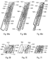
- the figures 47 to 74c illustrate several variants of a second embodiment of the invention.
- This second embodiment relates to a simplified autoinjector, consisting of fewer parts, and therefore simpler and less expensive to manufacture and to assemble.
- the autoinjector comprises a lower body 1010, an actuator sleeve 1011, a spring 1012 of the actuator sleeve, a cover 1014, a control sleeve 1004, a piston rod 1005, a support pad 1006, three locking elements 1007, here in the form of balls, an injection spring 1008, a click member 1500, a wire 1021, and an outer shell 1022.
- the cover 1014 makes it possible in particular to lock the autoinjector during transport and storage. As long as this cover is assembled on the lower body 1010, it prevents any actuation of the actuator sleeve 1011, and therefore any triggering of the autoinjector.
- syringe A is a pre-filled syringe. It advantageously comprises a needle cap B which protects and isolates the needle before use of the autoinjector.
- this needle cap B is automatically removed when the cover 1014 is withdrawn from the lower body 1010.
- this second embodiment has several elements similar to the first embodiment, these similar elements being designated by reference numerals similar to those of the first embodiment, increased by 1000.
- the actuator sleeve referenced 11 in the first embodiment is now referenced 1011. Therefore, in the description of this second embodiment embodiment, it is mainly the differences with respect to the first embodiment that will be described, it being understood that the other elements and functions remain similar if not identical between the two embodiments.
- the main difference of this second embodiment is that the reservoir, in this case the syringe A, is fixed relative to the lower body 1010, relative to the control sleeve 1004 and relative to the outer shell 1022.
- the reservoir in this case the syringe A
- the actuator sleeve slides relative to the rest of the autoinjector. There is therefore no syringe displacement device in this second embodiment.
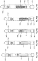
- the figures 48a to 48e illustrate the sequences of the use of the autoinjector of the figure 47 .
- the user wants to use the autoinjector, he takes the device, for example at the level of the outer shell 1022 and he presses the actuator sleeve 1011, which in a first projected position projects out of the lower body 1010, against the part of the body where he wants to perform the injection.
- the actuator sleeve 1011 causes the latter to slide towards the inside of the lower body 1010, which uncovers the needle and therefore its stitching due to the pressure exerted by the user on the autoinjector.
- the actuator sleeve 1011 When the actuator sleeve 1011 reaches its actuation position, which is its end position inside the lower body 1010, it triggers the injection phase, which is shown in the figures. figures 48c and 48d . It can be seen that the piston rod 1005 slides inside the syringe A by pushing the piston thereof under the effect of the injection spring 1008. The product is therefore dispensed.
- the actuator sleeve 1011 is again moved out of the lower body 1010 to a second projected position, under the effect of the spring of the actuator sleeve , with a locking of said actuator sleeve 1011, this which guarantees absolute safety for the user and avoids any risk of injury to the needle after use of the device.
- the first and second projected positions of the actuator sleeve which, in the example shown, are different positions, could possibly be identical.
- said actuator sleeve 1011 also comprises a flexible tab 1110 which is flexible only laterally, that is to say that it deforms only in the peripheral direction of the actuator sleeve 1011.
- An actuator sleeve 1011 provided with a such a flexible tab is even simpler to mold than the flexible dual-flexibility tab of the first embodiment, which is favorable from the point of view of manufacturing costs. With a flexible tab only laterally, it also saves radial size, which makes it possible in particular to improve the aesthetics of the autoinjector.
- the flexible tab 1110 advantageously comprises a rod part 1111 which is flexible and which ends in a head part 1112.
- said flexible tab 1110 is adapted to deform laterally relative to said lower body 1010 on the one hand when said actuator sleeve 1011 is moved from its first projected position towards its actuation position and on the other hand when said actuator sleeve 1011 is moved from its actuating position back to its second projected position.
- the head 1112 of the flexible tab must overcome resistance to deform laterally at the start of actuation, to create a kind of precompression which ensures that when the actuator sleeve will slide inwardly of the lower body 1010, the needle will repeatedly penetrate the injection site to its desired injection position.
- this resistance is formed by a shoulder 1019 of the lower body 1010.
- said flexible tab 1110 is not deformed when said actuator sleeve 1011 moves from its first projected position, before actuation, towards its actuation position, and said flexible tab is deformed laterally only when said actuator sleeve 1011 moves from its actuation position to its second projected position, at the end of use.
- the actuator sleeve 1011 before actuation, is connected to said lower body 1010 by at least one breakable bridge 1500.
- This embodiment allows in particular easy molding, and therefore reduced manufacturing costs, adaptation and management of the breaking force of breakable bridges facilitated by the sizing of these bridges, and a function of use indicator.
- the figure 52 illustrates two breakable bridges 1500, adapted to break and therefore to allow sliding of the actuator sleeve 1011 relative to the lower body 1010 when the user presses the autoinjector on the injection site with a predetermined pressure.
- the operation of the flexible tab 1110 may be identical. to that described in the context of the first embodiment, with an inclined groove, a final receiving zone and an axial shoulder cooperating with the head of the flexible tab to block it in the second projected position.
- the lower body 1010 may include a shoulder 1019 which extends axially inwardly by a ramp 1018, for example formed by a rib, which is at least partially inclined.
- a ramp 1018 for example formed by a rib, which is at least partially inclined.
- this same projection 1019 can cooperate with the head 1112 of the flexible tab 1110 both at the start of actuation to create the precompression and at the end of actuation to block the actuator sleeve in the second projected position.
- two different shoulders can also be provided to perform these two functions.
- the flexible tab 1110 can be fixed to said actuator sleeve 1011 only at the level of its rod portion 1111, with in this case the head 1112 forming a free end of said flexible tab.
- the flexible tab could also be fixed to said actuator sleeve on both sides, thus with the head 1112 disposed between the two fixing points. This implementation notably reinforces the robustness of the flexible tab.
- This variant could also be adapted to the flexible tab of the first embodiment.
- the flexible tab 1110 of the actuator sleeve 1011 advantageously cooperates with an opening 103, an inclined groove 104, a final receiving zone 105 and an axial shoulder 106 of the body 1010 which are similar to these same elements described above with reference to figures 4 to 18 .
- the figures 72 to 74c illustrate another variant embodiment of the actuator sleeve.
- the numerical references will be similar to those above, but increased by 1000.
- the actuator sleeve will be referenced 2011.
- the functions of the actuator sleeve 2011 and of the body 2010 are reversed, the body 2010 comprising the flexible tab 2110, and the actuator sleeve 2011 comprising the profile which will cooperate with said flexible tab 2110.
- the operation however remains similar to that described above, with the flexible tab 2110 which will gradually slide in said profile, and in particular in an inclined groove 2104 which connects an opening 2103 to a final reception zone 2105.
- the flexible tab 2110 will snap onto the shoulder 2106, as visible on the figure 74c .
- the flexible tab must advantageously overcome a resistance to deform at the start of the actuation, to create a kind of precompression which ensures that when the actuator sleeve 2011 will slide inwardly of the lower body 2010, the needle will always penetrate the injection site to its desired injection position. In the example of figures 72 to 74C , this resistance is formed by a shoulder 2019 of the actuator sleeve 2011.
- the flexible tab 2110 can be formed integrally on the body 2010, or as a variant be formed on a separate part assembled on said body 2010, by example for reasons of simplification and / or molding.
- the figures 53a, b, 54a, b , 57a, b, c and 58a, b, c illustrate the adaptation to the second embodiment of the injection lock described in the first embodiment.
- the autoinjector comprises injection means, comprising in particular the piston rod 1005 and the injection spring 1008, these injection means being blocked in a position loaded by said injection lock. Unlocking said injection lock then causes actuation of said injection means and therefore injection of the fluid product through the needle.
- said injection lock comprises a control sleeve 1004 disposed in said outer shell 1022, said control sleeve 1004 containing said piston rod 1005, said injection spring 1008 and a support pad 1006.
- the injection spring 1008 cooperates on the one hand with the piston rod 1005 and on the other hand with said support pellet 1006.
- This support pellet 1006 is formed by a ring arranged around said piston rod 1005.
- piston 1005 comprising at least one radial recess 1050 receiving at least one locking element 1007 movable between a locking position and an unlocking position.
- locking elements 1007 there are three locking elements 1007, preferably of substantially spherical shape, in particular in the form of balls, but a different number of locking elements and different rounded shapes of these locking elements are possible.
- Said locking elements 1007 are urged radially outwards by said piston rod 1005 and are retained in the locking position by a locking member, which in this second embodiment is formed by said control sleeve 1004.
- This control sleeve 1004 is movable axially relative to said piston rod 1005 between a locking position, in which it maintains the locking elements 1007 in the locking position, and an unlocking position, in which said blocking elements 1007 are released to thereby unlock said injection lock, allowing said injection spring to move said piston rod 1005 to its injection position.
- the control sleeve 1004 comprises one or more windows 1400 which allow the passage of the locking elements 1007 when the control sleeve has been moved to its unlocking position, shown in particular on the figures 58 .
- the movement of the control sleeve 1004 from its locked position to its unlocked position is achieved by a projection 1411 of the actuator sleeve 1011, which will cooperate with a shoulder 1410 of the control sleeve 1004, such that the control sleeve 1004 is in the unlocked position when the actuator sleeve 1011 is in the actuation position.
- Said piston rod 1005 then no longer being blocked by said locking elements 1007, it is moved out of the control sleeve by said pre-compressed injection spring 1008 to move the piston into the reservoir and thus inject the product through the needle.
- This type of lock allows low-effort unlocking, thus guaranteeing sound and tactile comfort to the user during injection.
- the autoinjector comprises an audible and / or tactile indication device 1500 to indicate by an audible sound or by a tactile indication to the user that the injection phase has ended.
- This device will be described below in relation to three variants of the second embodiment, but it could also be adapted to an autoinjector produced according to the first embodiment.
- this sound and / or tactile indication device 1500 comprises a central part 1501 provided with at least one side part 1502 connected to said central part 1501 by a foldable and / or breakable connection 1503.
- this sound and / or tactile indication device 1500 comprises a central part 1501 provided with at least one side part 1502 connected to said central part 1501 by a foldable and / or breakable connection 1503.
- the central part 1501 is connected to said piston rod 1005 by said wire 1021, which is fixed on the one hand on said central part 1501 and on the other hand on said piston rod 1005.
- the wire 1021 is wound around the piston rod and the central part 1501 is disposed outside the control sleeve 1004.
- the control sleeve 1004 is moved to its position of unlocking, shown in particular on the figure 58a , an upper edge of said control sleeve 1004 comes into contact with said side pieces 1502.
- the wire 1021 will gradually unwind to be stretched at the end of the injection as shown in figure 58b .
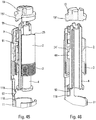
- the figures 60 to 64c illustrate a second variant of the sound and / or tactile indication device.
- the audible and / or tactile indication device 1500 comprises a movable element which is here formed by the control sleeve 1004, which comprises at its end distal relative to the needle, one or more deformable tabs 1510 which at the end of the injection will abut against the outer shell 1022.
- This sleeve of control 1004 is in a first position relative to the outer shell 1022 before actuation of the autoinjector, as shown in figure figure 64a .
- a central part called key 1120 here advantageously replaces the thread of the first previous variant.
- This key 1120 especially visible on the figures 63a and 63b , comprises a rod portion 1121 which extends inside the piston rod 1005, this rod portion being similar to the thread of the first variant.
- the key 1120 also includes a head portion 1122, disposed at the upper end (or distal to the needle) of said key. This head part cooperates with said deformable tabs 1510 of the control sleeve 1004, to prevent them from deforming radially inwards.
- these deformable tabs 1510 block said control sleeve in its second position relative to said outer shell 1022.
- the lower end (or proximal to the needle) of the rod portion 1121 cooperates with the rod of piston 1005 at the very end of the injection, causing said key 1120 to slide relative to the control sleeve 1004 and to the outer shell 1022.
- the head part 1122 no longer cooperates with the tabs 1510 of the sleeve control, which can then deform radially inward.
- This has the effect of unlocking the control sleeve 1004, which is then moved to a third position against said outer shell 1022 under the effect of the force exerted by the injection spring 1008. This creates a shock audible or otherwise detectable by the user, who then knows that the injection is complete.
- the outer shell 1022 comprises one or more, in particular three, viewing windows 1023 in which said deformable tabs 1510 become visible at the same time as they strike. against the outer shell. This allows visual indication simultaneously with the audible and / or tactile indication.
- said at least one viewing window 1023 is formed on or in the distal end edge of said outer shell 1022, being visible both in the axial direction and in the radial direction of said shell.
- This implementation avoids masking the viewing window (s) 1023 when the autoinjector is handled by the user, which guarantees good viewing of the information displayed in said at least one viewing window 1023 during the entire phase d. use, from start to finish.
- several viewing windows 1023, in particular three, distributed around the distal end edge of the body 1022 perfect viewing is guaranteed regardless of the orientation of the autoinjector at the time of its use.
- the alternative embodiments of the second embodiment of the autoinjector described above therefore define a control sleeve 1004 having three distinct positions: before injection when it is in the locked position, during injection when it is in the unlocked position, and after injection when he has activated the audible and / or tactile indication device. This makes it possible to easily visualize these three distinct positions in an appropriate viewing window 1221.
- the outer shell 1022 of this second embodiment could furthermore also include several viewing windows as described in the first embodiment.
- the figures 65 to 71 illustrate a third variant embodiment of the sound and / or tactile indication device.
- the mobile element of the sound and / or tactile indication device is not formed by the control sleeve 1004 but by the support pad 1006 on which s 'presses the injection spring 1008.
- the figures 66a and 66b shows this support patch, which comprises one or more deformable tabs 1520, which are similar to the deformable tabs 1510 of the control sleeve 1004 of the second variant above.
- the operation is also similar, with the key 1120 which blocks by its head 1122 the radial deformation of said tabs 1520, which blocks the pellet support relative to the outer shell.
- a visual indication is also provided by one or more viewing windows 1023 of the outer shell which show the deformable tabs 1520 of the support pad 1006.
- the figures 69 to 71 illustrate in more detail the operation of the sound and / or tactile indication device.
- the deformable tab 1520 is prevented from deforming radially inwards by the presence of the head part 1122 of the key 1120.
- the key has been moved by the piston rod, and as a result, the deformable tab 1520 has deformed radially inward. This caused the displacement of the support pad 1006 in the outer shell, with a shoulder 1521 of the deformable tab which abuts on a part of said outer shell, generating the sound and / or tactile indication, for example an audible sound. or a sensitive vibration.
- the end of the deformable tab 1520 is positioned in the window 1023 of the outer shell 1022, as visible on the figure.
- figure 70 illustrates the end of the injection, with the piston rod 1005 which will pull on the rod part 1121 of the key 1120 to move the latter.
- the present invention applies to devices used in particular for the treatment of autoimmune diseases, for example of the rheumatoid arthritis, multiple sclerosis, Crohn's disease type, for treatments against cancer, for antiviral treatments, for example of the type hepatitis, for treatment against diabetes, for treatment against anemia or for treatment of attacks, for example in the event of anaphylactic shock.
- autoimmune diseases for example of the rheumatoid arthritis, multiple sclerosis, Crohn's disease type
- antiviral treatments for example of the type hepatitis
- diabetes for treatment against anemia or for treatment of attacks, for example in the event of anaphylactic shock.
- the actuator sleeve and / or the syringe displacement device for pricking and / or retraction and / or the injection lock and / or the delay device and / or the sound and / or tactile indication device could be used independently of each other.
- the pricking of the needle and / or the retraction of the needle after injection could be controlled by one or more button (s).
- the sound and / or tactile indication device of the second embodiment could be used with an autoinjector of the type described in the first embodiment.
- Other modifications are also possible for those skilled in the art without departing from the scope of the present invention as defined by the appended claims.
Landscapes
- Health & Medical Sciences (AREA)
- Engineering & Computer Science (AREA)
- Hematology (AREA)
- Anesthesiology (AREA)
- Biomedical Technology (AREA)
- Heart & Thoracic Surgery (AREA)
- Vascular Medicine (AREA)
- Life Sciences & Earth Sciences (AREA)
- Animal Behavior & Ethology (AREA)
- General Health & Medical Sciences (AREA)
- Public Health (AREA)
- Veterinary Medicine (AREA)
- Environmental & Geological Engineering (AREA)
- Infusion, Injection, And Reservoir Apparatuses (AREA)
Applications Claiming Priority (4)
| Application Number | Priority Date | Filing Date | Title |
|---|---|---|---|
| FR1259123A FR2995790B1 (fr) | 2012-09-27 | 2012-09-27 | Autoinjecteur |
| FR1352518A FR3003470B1 (fr) | 2013-03-21 | 2013-03-21 | Autoinjecteur |
| EP13731360.7A EP2900299B1 (fr) | 2012-09-27 | 2013-05-24 | Autoinjecteur |
| PCT/FR2013/051144 WO2014049214A1 (fr) | 2012-09-27 | 2013-05-24 | Autoinjecteur |
Related Parent Applications (2)
| Application Number | Title | Priority Date | Filing Date |
|---|---|---|---|
| EP13731360.7A Division EP2900299B1 (fr) | 2012-09-27 | 2013-05-24 | Autoinjecteur |
| EP13731360.7A Division-Into EP2900299B1 (fr) | 2012-09-27 | 2013-05-24 | Autoinjecteur |
Publications (2)
| Publication Number | Publication Date |
|---|---|
| EP3308814A1 EP3308814A1 (fr) | 2018-04-18 |
| EP3308814B1 true EP3308814B1 (fr) | 2020-11-18 |
Family
ID=53488055
Family Applications (2)
| Application Number | Title | Priority Date | Filing Date |
|---|---|---|---|
| EP13731360.7A Active EP2900299B1 (fr) | 2012-09-27 | 2013-05-24 | Autoinjecteur |
| EP17202883.9A Active EP3308814B1 (fr) | 2012-09-27 | 2013-05-24 | Autoinjecteur |
Family Applications Before (1)
| Application Number | Title | Priority Date | Filing Date |
|---|---|---|---|
| EP13731360.7A Active EP2900299B1 (fr) | 2012-09-27 | 2013-05-24 | Autoinjecteur |
Country Status (5)
| Country | Link |
|---|---|
| EP (2) | EP2900299B1 (zh) |
| JP (1) | JP6196311B2 (zh) |
| CN (2) | CN104768592B (zh) |
| IN (1) | IN2015DN01589A (zh) |
| WO (1) | WO2014049214A1 (zh) |
Families Citing this family (13)
| Publication number | Priority date | Publication date | Assignee | Title |
|---|---|---|---|---|
| FI2822618T3 (fi) * | 2012-03-06 | 2024-03-21 | Antares Pharma Inc | Esitäytetty injektioruisku laukeamisvoimaominaisuuden kera |
| FR3019749B1 (fr) | 2014-04-11 | 2016-05-13 | Aptar France Sas | Autoinjecteur |
| GB2545266B (en) * | 2015-12-11 | 2018-08-08 | Oval Medical Tech Limited | Autoinjector with retracting needle |
| TWI551320B (zh) * | 2015-12-22 | 2016-10-01 | 佳承精工股份有限公司 | 安全注射裝置 |
| CN107648704B (zh) * | 2016-07-26 | 2022-02-15 | 广东东阳光药业有限公司 | 一种注射器用传动结构及注射器 |
| GB201616709D0 (en) | 2016-09-30 | 2016-11-16 | Owen Mumford Ltd | Injection device |
| EP3562529A4 (en) * | 2016-12-27 | 2021-03-03 | Action Medical Technologies, LLC | APPARATUS AND METHOD FOR INJECTING MEDICINES |
| US11224696B2 (en) | 2018-07-10 | 2022-01-18 | Action Medical Technologies, Llc | Apparatuses and method for injecting medicaments |
| GB2577537A (en) * | 2018-09-28 | 2020-04-01 | Owen Mumford Ltd | Injection device fill volume management |
| FR3094644B1 (fr) * | 2019-04-04 | 2021-06-04 | Aptar France Sas | Dispositif d'injection de produit fluide |
| US11065392B1 (en) | 2020-03-25 | 2021-07-20 | Action Medical Technologies, Llc | Apparatuses and methods for injecting medicaments |
| US11759576B2 (en) | 2020-06-05 | 2023-09-19 | Action Medical Technologies, Llc | Parenteral injection apparatus |
| CN115040727B (zh) * | 2022-06-06 | 2024-07-05 | 苏州恒瑞宏远医疗科技有限公司 | 注射装置 |
Family Cites Families (31)
| Publication number | Priority date | Publication date | Assignee | Title |
|---|---|---|---|---|
| FR2733155B1 (fr) | 1995-04-18 | 1997-09-19 | Tebro | Auto-injecteur rechargeable |
| GB2396816A (en) | 2002-12-17 | 2004-07-07 | Pa Consulting Services | Injection device |
| US7500963B2 (en) * | 2003-07-22 | 2009-03-10 | Safety Syringes, Inc. | Systems and methods for automatic medical injection with safeguard |
| DE102004052219A1 (de) * | 2004-10-27 | 2006-05-04 | Tecpharma Licensing Ag | Verabreichungsgerät mit akustischem Signal |
| FR2884722A1 (fr) | 2005-04-20 | 2006-10-27 | Becton Dickinson France Soc Pa | Ensemble d'injection et dispositif d'assistance |
| DE602005014631D1 (de) | 2005-07-15 | 2009-07-09 | Shl Group Ab | Injektor mit automatischem Einstechen der Nadel, Injektion und Retraktion der Nadel |
| FR2905273B1 (fr) | 2006-09-06 | 2009-04-03 | Becton Dickinson France Soc Pa | Dispositif d'injection automatique avec moyen de temporisation. |
| BRPI0808709A2 (pt) | 2007-03-09 | 2014-09-09 | Lilly Co Eli | Mecanismo de atrso para dispositivo de injeção automático |
| US8057427B2 (en) | 2007-05-09 | 2011-11-15 | Meridian Medical Technologies, Inc. | Drug delivery system with a small amount of a therapeutic agent |
| AU2008300703B2 (en) | 2007-09-18 | 2011-03-17 | Shl Group Ab | Automatic injection device with needle insertion |
| WO2009040602A1 (en) | 2007-09-25 | 2009-04-02 | Becton Dickinson France | Autoinject0r with deactivating means moveable by a safety shield |
| US8500693B2 (en) | 2007-09-25 | 2013-08-06 | Becton Dickinson France | Autoinjector received in external socket |
| US8357125B2 (en) | 2007-09-25 | 2013-01-22 | Becton, Dickinson And Company | Autoinjector with deactivating means moveable by a safety shield |
| EP2224980B1 (en) | 2007-11-12 | 2018-07-25 | Medicom Innovation Partner a/s | Auto injector with changing anchor locations for a mechanical driver |
| GB0801874D0 (en) | 2008-02-01 | 2008-03-12 | Liversidge Barry P | Injection device |
| EP2990067B1 (en) * | 2008-03-10 | 2019-09-04 | Antares Pharma, Inc. | Injector safety device |
| GB2463034B (en) | 2008-08-28 | 2012-11-07 | Owen Mumford Ltd | Autoinjection devices |
| WO2010035057A1 (en) * | 2008-09-29 | 2010-04-01 | Becton Dickinson France | Autoinjector with audible indication of completed delivery |
| WO2010035056A1 (en) * | 2008-09-29 | 2010-04-01 | Becton Dickinson France | Automatic injection device with sensitive indicator of completed injection |
| US8979807B2 (en) * | 2008-09-29 | 2015-03-17 | Becton Dickinson France | Automatic injection device with audible indicator of completed injection |
| US8579865B2 (en) | 2009-03-20 | 2013-11-12 | Antares Pharma, Inc. | Hazardous agent injection system |
| EP3366337B1 (en) | 2009-10-21 | 2019-12-04 | Owen Mumford Limited | Autoinjector |
| DK3733231T3 (da) * | 2009-12-01 | 2022-03-07 | Becton Dickinson Co | Injektionspen med automatisk tilbagetrækning (dial back) og styring af sidste dosis |
| WO2011101380A1 (en) | 2010-02-18 | 2011-08-25 | Sanofi-Aventis Deutschland Gmbh | Auto-injector |
| DK2538996T3 (da) | 2010-02-22 | 2020-08-10 | Sanofi Aventis Deutschland | Autoinjektor med nålehylster og nålebeskyttelseshætte |
| EP2399632A1 (en) | 2010-06-28 | 2011-12-28 | Sanofi-Aventis Deutschland GmbH | Auto injector with a single compression spring and a laterraly trigger button |
| EP2399628A1 (en) | 2010-06-28 | 2011-12-28 | Sanofi-Aventis Deutschland GmbH | Auto-injector |
| JP6057894B2 (ja) | 2010-07-02 | 2017-01-11 | サノフィ−アベンティス・ドイチュラント・ゲゼルシャフト・ミット・ベシュレンクテル・ハフツング | 充填済みシリンジ、注射デバイスおよび注射キットのための安全デバイス |
| JP6173210B2 (ja) | 2010-08-19 | 2017-08-02 | ノボ・ノルデイスク・エー/エス | 針シールド、減衰機構、及び聴覚と触覚によるフィードバックを有する、針を手動で挿入するための医療用自動注射装置 |
| MY159004A (en) | 2010-10-08 | 2016-11-30 | Sanofi Aventis Deutschland | Auto-injector |
| EP2489380A1 (en) * | 2011-02-18 | 2012-08-22 | Sanofi-Aventis Deutschland GmbH | Injection device |
-
2013
- 2013-05-24 CN CN201380056615.XA patent/CN104768592B/zh active Active
- 2013-05-24 WO PCT/FR2013/051144 patent/WO2014049214A1/fr active Application Filing
- 2013-05-24 EP EP13731360.7A patent/EP2900299B1/fr active Active
- 2013-05-24 EP EP17202883.9A patent/EP3308814B1/fr active Active
- 2013-05-24 CN CN201611112115.5A patent/CN106668991B/zh active Active
- 2013-05-24 IN IN1589DEN2015 patent/IN2015DN01589A/en unknown
- 2013-05-24 JP JP2015533657A patent/JP6196311B2/ja active Active
Non-Patent Citations (1)
| Title |
|---|
| None * |
Also Published As
| Publication number | Publication date |
|---|---|
| CN106668991A (zh) | 2017-05-17 |
| EP2900299A1 (fr) | 2015-08-05 |
| WO2014049214A1 (fr) | 2014-04-03 |
| JP6196311B2 (ja) | 2017-09-13 |
| CN104768592A (zh) | 2015-07-08 |
| EP3308814A1 (fr) | 2018-04-18 |
| IN2015DN01589A (zh) | 2015-07-03 |
| EP2900299B1 (fr) | 2020-07-08 |
| CN104768592B (zh) | 2017-05-17 |
| JP2015530170A (ja) | 2015-10-15 |
| CN106668991B (zh) | 2020-03-24 |
Similar Documents
| Publication | Publication Date | Title |
|---|---|---|
| EP2854903B1 (fr) | Autoinjecteur. | |
| EP3308814B1 (fr) | Autoinjecteur | |
| EP2854904B1 (fr) | Autoinjecteur | |
| EP2854901B1 (fr) | Autoinjecteur avec un retardateur ayant un train épicycloidal pour retarder la retraction de l'aiguille | |
| EP2854899B1 (fr) | Autoinjecteur | |
| EP3302647B1 (fr) | Autoinjecteur avec un systeme retardateur | |
| EP3302643A1 (fr) | Autoinjecteur avec un systeme retardateur du dispositif d'indication du retrait de l autoinjecteur | |
| WO2016193622A1 (fr) | Autoinjecteur. | |
| EP3352819B1 (fr) | Autoinjecteur | |
| FR2990868A1 (fr) | Autoinjecteur | |
| FR2990869A1 (fr) | Autoinjecteur | |
| FR2990866A1 (fr) | Autoinjecteur | |
| FR2990865A1 (fr) | Autoinjecteur | |
| EP3302646B1 (fr) | Autoinjecteur avec un dispositif retardateur comportant un train epicycloidal | |
| FR2990870A1 (fr) | Autoinjecteur. | |
| FR2990864A1 (fr) | Autoinjecteur | |
| FR2990863A1 (fr) | Autoinjecteur | |
| FR3003470A1 (fr) | Autoinjecteur | |
| FR3003469A1 (fr) | Autoinjecteur | |
| FR2995790A1 (fr) | Autoinjecteur |
Legal Events
| Date | Code | Title | Description |
|---|---|---|---|
| PUAI | Public reference made under article 153(3) epc to a published international application that has entered the european phase |
Free format text: ORIGINAL CODE: 0009012 |
|
| STAA | Information on the status of an ep patent application or granted ep patent |
Free format text: STATUS: THE APPLICATION HAS BEEN PUBLISHED |
|
| AC | Divisional application: reference to earlier application |
Ref document number: 2900299 Country of ref document: EP Kind code of ref document: P |
|
| AK | Designated contracting states |
Kind code of ref document: A1 Designated state(s): AL AT BE BG CH CY CZ DE DK EE ES FI FR GB GR HR HU IE IS IT LI LT LU LV MC MK MT NL NO PL PT RO RS SE SI SK SM TR |
|
| STAA | Information on the status of an ep patent application or granted ep patent |
Free format text: STATUS: REQUEST FOR EXAMINATION WAS MADE |
|
| 17P | Request for examination filed |
Effective date: 20181018 |
|
| RBV | Designated contracting states (corrected) |
Designated state(s): AL AT BE BG CH CY CZ DE DK EE ES FI FR GB GR HR HU IE IS IT LI LT LU LV MC MK MT NL NO PL PT RO RS SE SI SK SM TR |
|
| STAA | Information on the status of an ep patent application or granted ep patent |
Free format text: STATUS: EXAMINATION IS IN PROGRESS |
|
| 17Q | First examination report despatched |
Effective date: 20190306 |
|
| GRAP | Despatch of communication of intention to grant a patent |
Free format text: ORIGINAL CODE: EPIDOSNIGR1 |
|
| STAA | Information on the status of an ep patent application or granted ep patent |
Free format text: STATUS: GRANT OF PATENT IS INTENDED |
|
| RIC1 | Information provided on ipc code assigned before grant |
Ipc: A61M 5/00 20060101ALN20200514BHEP Ipc: A61M 5/31 20060101ALI20200514BHEP Ipc: A61M 5/20 20060101AFI20200514BHEP Ipc: A61M 5/32 20060101ALI20200514BHEP Ipc: A61M 5/315 20060101ALI20200514BHEP |
|
| INTG | Intention to grant announced |
Effective date: 20200616 |
|
| GRAS | Grant fee paid |
Free format text: ORIGINAL CODE: EPIDOSNIGR3 |
|
| GRAA | (expected) grant |
Free format text: ORIGINAL CODE: 0009210 |
|
| STAA | Information on the status of an ep patent application or granted ep patent |
Free format text: STATUS: THE PATENT HAS BEEN GRANTED |
|
| AC | Divisional application: reference to earlier application |
Ref document number: 2900299 Country of ref document: EP Kind code of ref document: P |
|
| AK | Designated contracting states |
Kind code of ref document: B1 Designated state(s): AL AT BE BG CH CY CZ DE DK EE ES FI FR GB GR HR HU IE IS IT LI LT LU LV MC MK MT NL NO PL PT RO RS SE SI SK SM TR |
|
| REG | Reference to a national code |
Ref country code: GB Ref legal event code: FG4D Free format text: NOT ENGLISH |
|
| REG | Reference to a national code |
Ref country code: CH Ref legal event code: EP |
|
| REG | Reference to a national code |
Ref country code: IE Ref legal event code: FG4D Free format text: LANGUAGE OF EP DOCUMENT: FRENCH |
|
| REG | Reference to a national code |
Ref country code: DE Ref legal event code: R096 Ref document number: 602013074223 Country of ref document: DE |
|
| REG | Reference to a national code |
Ref country code: AT Ref legal event code: REF Ref document number: 1335064 Country of ref document: AT Kind code of ref document: T Effective date: 20201215 |
|
| REG | Reference to a national code |
Ref country code: AT Ref legal event code: MK05 Ref document number: 1335064 Country of ref document: AT Kind code of ref document: T Effective date: 20201118 |
|
| REG | Reference to a national code |
Ref country code: NL Ref legal event code: MP Effective date: 20201118 |
|
| PG25 | Lapsed in a contracting state [announced via postgrant information from national office to epo] |
Ref country code: NO Free format text: LAPSE BECAUSE OF FAILURE TO SUBMIT A TRANSLATION OF THE DESCRIPTION OR TO PAY THE FEE WITHIN THE PRESCRIBED TIME-LIMIT Effective date: 20210218 Ref country code: RS Free format text: LAPSE BECAUSE OF FAILURE TO SUBMIT A TRANSLATION OF THE DESCRIPTION OR TO PAY THE FEE WITHIN THE PRESCRIBED TIME-LIMIT Effective date: 20201118 Ref country code: PT Free format text: LAPSE BECAUSE OF FAILURE TO SUBMIT A TRANSLATION OF THE DESCRIPTION OR TO PAY THE FEE WITHIN THE PRESCRIBED TIME-LIMIT Effective date: 20210318 Ref country code: GR Free format text: LAPSE BECAUSE OF FAILURE TO SUBMIT A TRANSLATION OF THE DESCRIPTION OR TO PAY THE FEE WITHIN THE PRESCRIBED TIME-LIMIT Effective date: 20210219 Ref country code: FI Free format text: LAPSE BECAUSE OF FAILURE TO SUBMIT A TRANSLATION OF THE DESCRIPTION OR TO PAY THE FEE WITHIN THE PRESCRIBED TIME-LIMIT Effective date: 20201118 |
|
| PG25 | Lapsed in a contracting state [announced via postgrant information from national office to epo] |
Ref country code: SE Free format text: LAPSE BECAUSE OF FAILURE TO SUBMIT A TRANSLATION OF THE DESCRIPTION OR TO PAY THE FEE WITHIN THE PRESCRIBED TIME-LIMIT Effective date: 20201118 Ref country code: BG Free format text: LAPSE BECAUSE OF FAILURE TO SUBMIT A TRANSLATION OF THE DESCRIPTION OR TO PAY THE FEE WITHIN THE PRESCRIBED TIME-LIMIT Effective date: 20210218 Ref country code: PL Free format text: LAPSE BECAUSE OF FAILURE TO SUBMIT A TRANSLATION OF THE DESCRIPTION OR TO PAY THE FEE WITHIN THE PRESCRIBED TIME-LIMIT Effective date: 20201118 Ref country code: LV Free format text: LAPSE BECAUSE OF FAILURE TO SUBMIT A TRANSLATION OF THE DESCRIPTION OR TO PAY THE FEE WITHIN THE PRESCRIBED TIME-LIMIT Effective date: 20201118 Ref country code: IS Free format text: LAPSE BECAUSE OF FAILURE TO SUBMIT A TRANSLATION OF THE DESCRIPTION OR TO PAY THE FEE WITHIN THE PRESCRIBED TIME-LIMIT Effective date: 20210318 Ref country code: AT Free format text: LAPSE BECAUSE OF FAILURE TO SUBMIT A TRANSLATION OF THE DESCRIPTION OR TO PAY THE FEE WITHIN THE PRESCRIBED TIME-LIMIT Effective date: 20201118 |
|
| REG | Reference to a national code |
Ref country code: LT Ref legal event code: MG9D |
|
| PG25 | Lapsed in a contracting state [announced via postgrant information from national office to epo] |
Ref country code: HR Free format text: LAPSE BECAUSE OF FAILURE TO SUBMIT A TRANSLATION OF THE DESCRIPTION OR TO PAY THE FEE WITHIN THE PRESCRIBED TIME-LIMIT Effective date: 20201118 |
|
| PG25 | Lapsed in a contracting state [announced via postgrant information from national office to epo] |
Ref country code: SK Free format text: LAPSE BECAUSE OF FAILURE TO SUBMIT A TRANSLATION OF THE DESCRIPTION OR TO PAY THE FEE WITHIN THE PRESCRIBED TIME-LIMIT Effective date: 20201118 Ref country code: RO Free format text: LAPSE BECAUSE OF FAILURE TO SUBMIT A TRANSLATION OF THE DESCRIPTION OR TO PAY THE FEE WITHIN THE PRESCRIBED TIME-LIMIT Effective date: 20201118 Ref country code: SM Free format text: LAPSE BECAUSE OF FAILURE TO SUBMIT A TRANSLATION OF THE DESCRIPTION OR TO PAY THE FEE WITHIN THE PRESCRIBED TIME-LIMIT Effective date: 20201118 Ref country code: EE Free format text: LAPSE BECAUSE OF FAILURE TO SUBMIT A TRANSLATION OF THE DESCRIPTION OR TO PAY THE FEE WITHIN THE PRESCRIBED TIME-LIMIT Effective date: 20201118 Ref country code: CZ Free format text: LAPSE BECAUSE OF FAILURE TO SUBMIT A TRANSLATION OF THE DESCRIPTION OR TO PAY THE FEE WITHIN THE PRESCRIBED TIME-LIMIT Effective date: 20201118 Ref country code: LT Free format text: LAPSE BECAUSE OF FAILURE TO SUBMIT A TRANSLATION OF THE DESCRIPTION OR TO PAY THE FEE WITHIN THE PRESCRIBED TIME-LIMIT Effective date: 20201118 |
|
| REG | Reference to a national code |
Ref country code: DE Ref legal event code: R097 Ref document number: 602013074223 Country of ref document: DE |
|
| PG25 | Lapsed in a contracting state [announced via postgrant information from national office to epo] |
Ref country code: DK Free format text: LAPSE BECAUSE OF FAILURE TO SUBMIT A TRANSLATION OF THE DESCRIPTION OR TO PAY THE FEE WITHIN THE PRESCRIBED TIME-LIMIT Effective date: 20201118 |
|
| PLBE | No opposition filed within time limit |
Free format text: ORIGINAL CODE: 0009261 |
|
| STAA | Information on the status of an ep patent application or granted ep patent |
Free format text: STATUS: NO OPPOSITION FILED WITHIN TIME LIMIT |
|
| 26N | No opposition filed |
Effective date: 20210819 |
|
| PG25 | Lapsed in a contracting state [announced via postgrant information from national office to epo] |
Ref country code: NL Free format text: LAPSE BECAUSE OF FAILURE TO SUBMIT A TRANSLATION OF THE DESCRIPTION OR TO PAY THE FEE WITHIN THE PRESCRIBED TIME-LIMIT Effective date: 20201118 Ref country code: AL Free format text: LAPSE BECAUSE OF FAILURE TO SUBMIT A TRANSLATION OF THE DESCRIPTION OR TO PAY THE FEE WITHIN THE PRESCRIBED TIME-LIMIT Effective date: 20201118 |
|
| PG25 | Lapsed in a contracting state [announced via postgrant information from national office to epo] |
Ref country code: SI Free format text: LAPSE BECAUSE OF FAILURE TO SUBMIT A TRANSLATION OF THE DESCRIPTION OR TO PAY THE FEE WITHIN THE PRESCRIBED TIME-LIMIT Effective date: 20201118 |
|
| REG | Reference to a national code |
Ref country code: CH Ref legal event code: PL |
|
| PG25 | Lapsed in a contracting state [announced via postgrant information from national office to epo] |
Ref country code: CH Free format text: LAPSE BECAUSE OF NON-PAYMENT OF DUE FEES Effective date: 20210531 Ref country code: MC Free format text: LAPSE BECAUSE OF FAILURE TO SUBMIT A TRANSLATION OF THE DESCRIPTION OR TO PAY THE FEE WITHIN THE PRESCRIBED TIME-LIMIT Effective date: 20201118 Ref country code: LI Free format text: LAPSE BECAUSE OF NON-PAYMENT OF DUE FEES Effective date: 20210531 Ref country code: LU Free format text: LAPSE BECAUSE OF NON-PAYMENT OF DUE FEES Effective date: 20210524 Ref country code: ES Free format text: LAPSE BECAUSE OF FAILURE TO SUBMIT A TRANSLATION OF THE DESCRIPTION OR TO PAY THE FEE WITHIN THE PRESCRIBED TIME-LIMIT Effective date: 20201118 |
|
| REG | Reference to a national code |
Ref country code: BE Ref legal event code: MM Effective date: 20210531 |
|
| PG25 | Lapsed in a contracting state [announced via postgrant information from national office to epo] |
Ref country code: IE Free format text: LAPSE BECAUSE OF NON-PAYMENT OF DUE FEES Effective date: 20210524 |
|
| PG25 | Lapsed in a contracting state [announced via postgrant information from national office to epo] |
Ref country code: IS Free format text: LAPSE BECAUSE OF FAILURE TO SUBMIT A TRANSLATION OF THE DESCRIPTION OR TO PAY THE FEE WITHIN THE PRESCRIBED TIME-LIMIT Effective date: 20210318 |
|
| PG25 | Lapsed in a contracting state [announced via postgrant information from national office to epo] |
Ref country code: BE Free format text: LAPSE BECAUSE OF NON-PAYMENT OF DUE FEES Effective date: 20210531 |
|
| PG25 | Lapsed in a contracting state [announced via postgrant information from national office to epo] |
Ref country code: CY Free format text: LAPSE BECAUSE OF FAILURE TO SUBMIT A TRANSLATION OF THE DESCRIPTION OR TO PAY THE FEE WITHIN THE PRESCRIBED TIME-LIMIT Effective date: 20201118 |
|
| P01 | Opt-out of the competence of the unified patent court (upc) registered |
Effective date: 20230526 |
|
| PG25 | Lapsed in a contracting state [announced via postgrant information from national office to epo] |
Ref country code: HU Free format text: LAPSE BECAUSE OF FAILURE TO SUBMIT A TRANSLATION OF THE DESCRIPTION OR TO PAY THE FEE WITHIN THE PRESCRIBED TIME-LIMIT; INVALID AB INITIO Effective date: 20130524 |
|
| PG25 | Lapsed in a contracting state [announced via postgrant information from national office to epo] |
Ref country code: MK Free format text: LAPSE BECAUSE OF FAILURE TO SUBMIT A TRANSLATION OF THE DESCRIPTION OR TO PAY THE FEE WITHIN THE PRESCRIBED TIME-LIMIT Effective date: 20201118 |
|
| PG25 | Lapsed in a contracting state [announced via postgrant information from national office to epo] |
Ref country code: TR Free format text: LAPSE BECAUSE OF FAILURE TO SUBMIT A TRANSLATION OF THE DESCRIPTION OR TO PAY THE FEE WITHIN THE PRESCRIBED TIME-LIMIT Effective date: 20201118 |
|
| PGFP | Annual fee paid to national office [announced via postgrant information from national office to epo] |
Ref country code: GB Payment date: 20240523 Year of fee payment: 12 |
|
| PGFP | Annual fee paid to national office [announced via postgrant information from national office to epo] |
Ref country code: DE Payment date: 20240513 Year of fee payment: 12 |
|
| PGFP | Annual fee paid to national office [announced via postgrant information from national office to epo] |
Ref country code: IT Payment date: 20240509 Year of fee payment: 12 Ref country code: FR Payment date: 20240528 Year of fee payment: 12 |