EP3308683A1 - Cooking vessel for an oven cavity of a cooking oven - Google Patents
Cooking vessel for an oven cavity of a cooking oven Download PDFInfo
- Publication number
- EP3308683A1 EP3308683A1 EP16193383.3A EP16193383A EP3308683A1 EP 3308683 A1 EP3308683 A1 EP 3308683A1 EP 16193383 A EP16193383 A EP 16193383A EP 3308683 A1 EP3308683 A1 EP 3308683A1
- Authority
- EP
- European Patent Office
- Prior art keywords
- cooking
- cooking vessel
- oven
- temperature sensor
- socket
- Prior art date
- Legal status (The legal status is an assumption and is not a legal conclusion. Google has not performed a legal analysis and makes no representation as to the accuracy of the status listed.)
- Granted
Links
- 238000010411 cooking Methods 0.000 title claims abstract description 138
- 229920000642 polymer Polymers 0.000 claims abstract description 7
- 229920003023 plastic Polymers 0.000 claims abstract description 6
- 235000013305 food Nutrition 0.000 claims description 14
- 238000009423 ventilation Methods 0.000 claims description 14
- 239000000523 sample Substances 0.000 claims description 10
- 230000005484 gravity Effects 0.000 claims description 3
- 238000007789 sealing Methods 0.000 claims description 3
- 238000000034 method Methods 0.000 description 9
- 238000005265 energy consumption Methods 0.000 description 3
- 239000000463 material Substances 0.000 description 3
- 102000008186 Collagen Human genes 0.000 description 2
- 108010035532 Collagen Proteins 0.000 description 2
- 229920001436 collagen Polymers 0.000 description 2
- 238000012986 modification Methods 0.000 description 2
- 230000004048 modification Effects 0.000 description 2
- 229920001601 polyetherimide Polymers 0.000 description 2
- 229920002472 Starch Polymers 0.000 description 1
- 238000004925 denaturation Methods 0.000 description 1
- 230000036425 denaturation Effects 0.000 description 1
- 230000001419 dependent effect Effects 0.000 description 1
- 230000007515 enzymatic degradation Effects 0.000 description 1
- 230000003301 hydrolyzing effect Effects 0.000 description 1
- 239000004973 liquid crystal related substance Substances 0.000 description 1
- 235000015097 nutrients Nutrition 0.000 description 1
- 102000004169 proteins and genes Human genes 0.000 description 1
- 108090000623 proteins and genes Proteins 0.000 description 1
- 235000019698 starch Nutrition 0.000 description 1
- 239000008107 starch Substances 0.000 description 1
- 230000008961 swelling Effects 0.000 description 1
- 235000013343 vitamin Nutrition 0.000 description 1
- 229940088594 vitamin Drugs 0.000 description 1
- 229930003231 vitamin Natural products 0.000 description 1
- 239000011782 vitamin Substances 0.000 description 1
Images


Classifications
-
- F—MECHANICAL ENGINEERING; LIGHTING; HEATING; WEAPONS; BLASTING
- F24—HEATING; RANGES; VENTILATING
- F24C—DOMESTIC STOVES OR RANGES ; DETAILS OF DOMESTIC STOVES OR RANGES, OF GENERAL APPLICATION
- F24C7/00—Stoves or ranges heated by electric energy
- F24C7/08—Arrangement or mounting of control or safety devices
- F24C7/082—Arrangement or mounting of control or safety devices on ranges, e.g. control panels, illumination
- F24C7/085—Arrangement or mounting of control or safety devices on ranges, e.g. control panels, illumination on baking ovens
-
- A—HUMAN NECESSITIES
- A47—FURNITURE; DOMESTIC ARTICLES OR APPLIANCES; COFFEE MILLS; SPICE MILLS; SUCTION CLEANERS IN GENERAL
- A47J—KITCHEN EQUIPMENT; COFFEE MILLS; SPICE MILLS; APPARATUS FOR MAKING BEVERAGES
- A47J36/00—Parts, details or accessories of cooking-vessels
- A47J36/02—Selection of specific materials, e.g. heavy bottoms with copper inlay or with insulating inlay
-
- A—HUMAN NECESSITIES
- A47—FURNITURE; DOMESTIC ARTICLES OR APPLIANCES; COFFEE MILLS; SPICE MILLS; SUCTION CLEANERS IN GENERAL
- A47J—KITCHEN EQUIPMENT; COFFEE MILLS; SPICE MILLS; APPARATUS FOR MAKING BEVERAGES
- A47J36/00—Parts, details or accessories of cooking-vessels
- A47J36/32—Time-controlled igniting mechanisms or alarm devices
- A47J36/321—Time-controlled igniting mechanisms or alarm devices the electronic control being performed over a network, e.g. by means of a handheld device
-
- A—HUMAN NECESSITIES
- A47—FURNITURE; DOMESTIC ARTICLES OR APPLIANCES; COFFEE MILLS; SPICE MILLS; SUCTION CLEANERS IN GENERAL
- A47J—KITCHEN EQUIPMENT; COFFEE MILLS; SPICE MILLS; APPARATUS FOR MAKING BEVERAGES
- A47J2202/00—Devices having temperature indicating means
Definitions
- the present invention relates to a cooking vessel for an oven cavity of a cooking oven. Further, the present invention relates to a cooking oven with an oven cavity and at least one cooking vessel.
- the cooking process in a casserole within an oven cavity has relative high energy consumption.
- the casserole is usually made of material having high heat capacity. Further, the control of the cooking process in the casserole is difficult.
- the object is achieved by the cooking vessel for an oven cavity of a cooking oven according to claim 1.
- a cooking vessel for an oven cavity of a cooking oven is provided, wherein:
- the core of the present invention is that the cooking vessel is made of the temperature resistant polymer or plastic on the one hand and the arrangement of the temperature sensor in said cooking vessel on the other hand, wherein the temperature sensor is connectable or connected to the control unit of the cooking oven.
- the cooking process in the cooking vessel can be directly controlled.
- the temperature sensor is connectable or connected to an oven socket via a cable, so that the temperature sensor can communicate with the control unit of the cooking oven.
- the lower part comprises a vessel socket for receiving a food probe including the temperature sensor, wherein said vessel socket is formed in the bottom of the lower part.
- the lower part may comprise a socket for receiving an electric plug of the cable, wherein said socket is connected to the temperature sensor, and wherein preferably the temperature sensor is permanently or detachably arranged in the bottom of the lower part.
- the lower part is hard-wired with the cable, wherein preferably the cable includes a plug connectable to the oven socket of the cooking oven.
- the temperature sensor is connectable or connected to the control unit of the cooking oven via a wireless connection, for example an SAW or RFID connection.
- the upper part and the lower part include a planar contact surface in each case, so that the upper part and the lower part are tightly closable together by gravity, wherein preferably the upper part and/or the lower part include a rim, which prevents the upper part from getting out of place.
- the upper part and the lower part may include an interlocking system, wherein preferably at least one sealing is arrangeable or arranged between the upper part and the lower part.
- the upper part and the lower part include a bayonet closing system between said upper part and lower part.
- the upper part and the lower part are connectable or connected by ate least one clamp and/or hinge.
- the cooking vessel may include at least one automatic and/or manual pressure release system, wherein preferably said pressure release system limits the pressure inside the cooking vessel.
- the cooking vessel may include at least one lockable opening for controlling the loss of moisture in the cooking vessel, wherein preferably said lockable opening is a rotatable slider or a linearly movable slider.
- the cooking vessel comprises at least one ventilation opening including the lockable opening and the pressure release system mentioned above.
- the present invention relates to a cooking oven with an oven cavity and at least one cooking vessel mentioned above, wherein
- the present invention relates to an alternative cooking oven with the oven cavity and at least one cooking vessel mentioned above, wherein
- FIG 1 illustrates a schematic front view of a cooking oven 10 with a cooking vessel 14 according to a preferred embodiment of the present invention.
- the cooking vessel 14 is arranged inside an oven cavity 12 of the cooking oven 10.
- the cooking vessel 14 includes an upper part 16 and a lower part 18.
- the upper part 16 and the lower part 18 form the closed cooking vessel 14.
- the lower part 18 is a casserole, while the upper part 16 is a lid.
- the cooking vessel 14 includes a temperature sensor 22.
- the temperature sensor 22 is arranged in the bottom of the lower part 18.
- the temperature sensor 22 is an NTC resistor element.
- the temperature sensor 22 is a part of a food probe 30 received by a vessel socket 28 in the bottom of the lower part 18.
- the food probe 30 with temperature sensor 22 is connected to an oven socket 34 of the cooking oven 10 via a cable 32.
- the upper part 16 and the lower part 18 include a planar contact surface in each case. Said planar contact surfaces allow a tight closing between the upper part 16 and the lower part 18 by gravity.
- the upper part 16 and/or the lower part 18 include a rim, which prevents the upper part 16 from getting out of place.
- the upper part 16 and the lower part 18 include an interlocking system, for example a bayonet closing system, clamps and/or hinges, wherein preferably a sealing is arranged between the upper part 16 and the lower part 18.
- the cooking vessel 14 comprises a ventilation opening 20 arranged in a top side of the upper part 16.
- Said ventilation opening 20 is optional, if the upper part 16 and the lower part 18 include the planar contact surfaces. However, the ventilation opening 20 is necessary or at least advantageous, if the upper part 16 and the lower part 18 include the interlocking system.
- the cooking vessel 14 is made of at least one temperature resistant polymer or plastic, for example of at least one of Liquid crystal polymere (LCP), Polyether-etherketon (PEEK) and/or Polyetherimid (PEI). Said polymer or plastic has a low heat capacity. More accurately, the heat capacity per volume of the polymer is low.
- the material of the cooking vessel 14 is food safe.
- the material of the cooking vessel 14 has an emissivity of at least 0.8, preferably bigger than about 0.8, which is a low value and contributes to low energy consumption. In particular, the emissivity can be between selected from the range of 0.8 to 1.
- the cooking vessel 14 is provided for different sizes.
- the volume of the cooking vessel 14 is one, two three, five or seven litre.
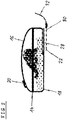
- FIG 2 illustrates a schematic front view of the cooking vessel 14 according to the preferred embodiment of the present invention.
- the upper part 16 and the lower part 18 form the closed cooking vessel 14.
- a vessel socket 28 is integrated in the bottom of the lower part 18.
- the vessel socket 28 is provided for receiving the food probe 30 with the temperature sensor 22.
- the food probe 30 is outside of the vessel socket 28.
- the food probe 30 is connectable via the cable 32 to the oven socket 34 of the cooking oven 10, so that the temperature sensor 22 is connectable to a control unit of the cooking oven 10.
- the cable 32 is connectable to the oven socket 34 via a plug.
- the plug for the oven socket 34 is a 3.5 mm or 6.35 mm phone jack.
- FIG 3 illustrates a schematic front view of the cooking vessel 14 according to the preferred embodiment of the present invention.
- the food probe 30 is inserted in the vessel socket 28.
- the lower part 18 includes a socket for a phone jack or the like in order to connect the cooking vessel 14 to the control unit of the cooking oven 10.
- the temperature sensor 22 is permanently or detachably arranged in the bottom of the lower part 18 and electrically connected to the socket.
- the lower part 18 is hard-wired with the cable 32.
- the cable 32 may include a plug, e.g. a jack phone, connectable to the oven socket 34 of the cooking oven 10.
- the food probe 30 with the temperature sensor 22 is connectable to the control unit of the cooking oven 10 via a wireless connection, for example SAW, RFID or the like.
- a wireless connection for example SAW, RFID or the like.
- an analogue temperature gauge is possible. Said temperature gauge may be monitored via camera and application software.
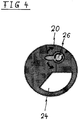
- FIG 4 illustrates a schematic top view of the ventilation opening 20 of the cooking vessel 14 according to the preferred embodiment of the present invention.
- the ventilation opening 20 is optional, if the upper part 16 and the lower part 18 include the planar contact surfaces.
- the ventilation opening 20 is necessary or at least advantageous, if the upper part 16 and the lower part 18 include the bayonet closing system, the clamps and/or the hinges.
- the ventilation opening 20 comprises a rotatable slider 24 and a pressure release system 26.
- the ventilation opening 20 may comprise a linearly movable slider.
- the rotatable slider 24 allows different opening widths.
- the rotatable slider 24 controls the loss of moisture in the cooking vessel 14 during the cooking process.
- the pressure release system 26 allows an automatic and/or manual reduction of an overpressure inside the closed cooking vessel 14. Moreover, the pressure inside the cooking vessel 14 can be reduced to ambient pressure after the cooking process.
- the present invention provides a light weight cooking vessel 14 with a low heat capacity.
- the tight closing of the upper part 16 and the lower part 18 prevents the food from moisture loss.
- the interlocking system for the upper part 16 and the lower part 18 allows pressure cooking modes.
- the pressure release system 26 of the ventilation opening 20 allows the automatic limitation of the pressure inside the cooking vessel 14.
- the rotatable slider 24 of the ventilation opening 20 allows the possibility to get rid of moisture, if the cooking recipe requires this.
- the integrated temperature sensor 22 allows an automatic and/or manual control of the cooking process.
- the temperature control during pressure cooking prevents a continuous pressure release.
- the user can monitor the cooking process in an easy way.
- Food usually cooked in a pot on a cooking hob may be prepared in the cooking vessel 14 inside the oven cavity 12 in a shorter time.
- vitamins and nutrients may be kept and energy is saved.
- temperature dependent cooking processes like enzymatic degradation of collagen, hydrolysing of collagen, swelling of starch or denaturation of protein are supported by the temperature control in the cooking vessel 14.
- the temperature control in the cooking vessel 14 allows the determination of the amount of food without scale.
Landscapes
- Engineering & Computer Science (AREA)
- Food Science & Technology (AREA)
- Chemical & Material Sciences (AREA)
- Combustion & Propulsion (AREA)
- Mechanical Engineering (AREA)
- General Engineering & Computer Science (AREA)
- Cookers (AREA)
Abstract
Description
- The present invention relates to a cooking vessel for an oven cavity of a cooking oven. Further, the present invention relates to a cooking oven with an oven cavity and at least one cooking vessel.
- The cooking process in a casserole within an oven cavity has relative high energy consumption. The casserole is usually made of material having high heat capacity. Further, the control of the cooking process in the casserole is difficult.
- It is an object of the present invention to provide a cooking vessel for an oven cavity of a cooking oven, which allows reduced energy consumption and an improved control of the cooking process.
- The object is achieved by the cooking vessel for an oven cavity of a cooking oven according to claim 1.
- According to the present invention a cooking vessel for an oven cavity of a cooking oven is provided, wherein:
- the cooking vessel includes an upper part and a lower part,
- the cooking vessel provides a closed space, when the upper part covers the lower part,
- the upper part and the lower part are made of at least one temperature resistant polymer or plastic,
- at least one temperature sensor is removably or permanently arranged in the bottom of the lower part, and
- the temperature sensor is connectable or connected to a control unit of the cooking oven.
- The core of the present invention is that the cooking vessel is made of the temperature resistant polymer or plastic on the one hand and the arrangement of the temperature sensor in said cooking vessel on the other hand, wherein the temperature sensor is connectable or connected to the control unit of the cooking oven. The cooking process in the cooking vessel can be directly controlled.
- Preferably, the temperature sensor is connectable or connected to an oven socket via a cable, so that the temperature sensor can communicate with the control unit of the cooking oven.
- In particular, the lower part comprises a vessel socket for receiving a food probe including the temperature sensor, wherein said vessel socket is formed in the bottom of the lower part.
- Alternatively, the lower part may comprise a socket for receiving an electric plug of the cable, wherein said socket is connected to the temperature sensor, and wherein preferably the temperature sensor is permanently or detachably arranged in the bottom of the lower part.
- According to a further alternative embodiment, the lower part is hard-wired with the cable, wherein preferably the cable includes a plug connectable to the oven socket of the cooking oven.
- According to another alternative embodiment, the temperature sensor is connectable or connected to the control unit of the cooking oven via a wireless connection, for example an SAW or RFID connection.
- For example, the upper part and the lower part include a planar contact surface in each case, so that the upper part and the lower part are tightly closable together by gravity, wherein preferably the upper part and/or the lower part include a rim, which prevents the upper part from getting out of place.
- Alternatively, the upper part and the lower part may include an interlocking system, wherein preferably at least one sealing is arrangeable or arranged between the upper part and the lower part.
- For example, the upper part and the lower part include a bayonet closing system between said upper part and lower part.
- According to another example, the upper part and the lower part are connectable or connected by ate least one clamp and/or hinge.
- Further, the cooking vessel may include at least one automatic and/or manual pressure release system, wherein preferably said pressure release system limits the pressure inside the cooking vessel.
- Moreover, the cooking vessel may include at least one lockable opening for controlling the loss of moisture in the cooking vessel, wherein preferably said lockable opening is a rotatable slider or a linearly movable slider.
- Preferably, the cooking vessel comprises at least one ventilation opening including the lockable opening and the pressure release system mentioned above.
- Further, the present invention relates to a cooking oven with an oven cavity and at least one cooking vessel mentioned above, wherein
- the oven cavity is provided for receiving the cooking vessel,
- the cooking oven includes at least one oven socket for receiving a plug of the cable connected or connectable to the at least one temperature sensor of the cooking vessel, and
- the oven socket is connected to the control unit of the cooking oven.
- At last, the present invention relates to an alternative cooking oven with the oven cavity and at least one cooking vessel mentioned above, wherein
- the oven cavity is provided for receiving the cooking vessel,
- the cooking oven includes means for at least one wireless connection to the at least one temperature sensor of the cooking vessel, and
- the means for the wireless connection are connected to the control unit of the cooking oven.
- Novel and inventive features of the present invention are set forth in the appended claims.
- The present invention will be described in further detail with reference to the drawings, in which
- FIG 1
- illustrates a schematic front view of a cooking oven with a cooking vessel according to a preferred embodiment of the present invention,
- FIG 2
- illustrates a schematic front view of the cooking vessel according to the preferred embodiment of the present invention,
- FIG 3
- illustrates a schematic front view of the cooking vessel according to the preferred embodiment of the present invention, and
- FIG 4
- illustrates a schematic top view of a ventilation opening of the cooking vessel according to the preferred embodiment of the present invention.
-
FIG 1 illustrates a schematic front view of acooking oven 10 with acooking vessel 14 according to a preferred embodiment of the present invention. Thecooking vessel 14 is arranged inside anoven cavity 12 of thecooking oven 10. - The
cooking vessel 14 includes anupper part 16 and alower part 18. Theupper part 16 and thelower part 18 form the closedcooking vessel 14. In this example, thelower part 18 is a casserole, while theupper part 16 is a lid. Thecooking vessel 14 includes atemperature sensor 22. In this example, thetemperature sensor 22 is arranged in the bottom of thelower part 18. Preferably, thetemperature sensor 22 is an NTC resistor element. Thetemperature sensor 22 is a part of afood probe 30 received by avessel socket 28 in the bottom of thelower part 18. Thefood probe 30 withtemperature sensor 22 is connected to anoven socket 34 of thecooking oven 10 via acable 32. - In this example, the
upper part 16 and thelower part 18 include a planar contact surface in each case. Said planar contact surfaces allow a tight closing between theupper part 16 and thelower part 18 by gravity. Preferably, theupper part 16 and/or thelower part 18 include a rim, which prevents theupper part 16 from getting out of place. Alternatively, theupper part 16 and thelower part 18 include an interlocking system, for example a bayonet closing system, clamps and/or hinges, wherein preferably a sealing is arranged between theupper part 16 and thelower part 18. - Further, the
cooking vessel 14 comprises a ventilation opening 20 arranged in a top side of theupper part 16. Said ventilation opening 20 is optional, if theupper part 16 and thelower part 18 include the planar contact surfaces. However, the ventilation opening 20 is necessary or at least advantageous, if theupper part 16 and thelower part 18 include the interlocking system. - The
cooking vessel 14 is made of at least one temperature resistant polymer or plastic, for example of at least one of Liquid crystal polymere (LCP), Polyether-etherketon (PEEK) and/or Polyetherimid (PEI). Said polymer or plastic has a low heat capacity. More accurately, the heat capacity per volume of the polymer is low. The material of thecooking vessel 14 is food safe. The material of thecooking vessel 14 has an emissivity of at least 0.8, preferably bigger than about 0.8, which is a low value and contributes to low energy consumption. In particular, the emissivity can be between selected from the range of 0.8 to 1. - The
cooking vessel 14 is provided for different sizes. For example, the volume of thecooking vessel 14 is one, two three, five or seven litre. -
FIG 2 illustrates a schematic front view of thecooking vessel 14 according to the preferred embodiment of the present invention. Theupper part 16 and thelower part 18 form theclosed cooking vessel 14. - A
vessel socket 28 is integrated in the bottom of thelower part 18. Thevessel socket 28 is provided for receiving thefood probe 30 with thetemperature sensor 22. InFIG 2 thefood probe 30 is outside of thevessel socket 28. Thefood probe 30 is connectable via thecable 32 to theoven socket 34 of thecooking oven 10, so that thetemperature sensor 22 is connectable to a control unit of thecooking oven 10. Thecable 32 is connectable to theoven socket 34 via a plug. For example, the plug for theoven socket 34 is a 3.5 mm or 6.35 mm phone jack. -
FIG 3 illustrates a schematic front view of thecooking vessel 14 according to the preferred embodiment of the present invention. InFIG 3 thefood probe 30 is inserted in thevessel socket 28. - According to another embodiment, the
lower part 18 includes a socket for a phone jack or the like in order to connect thecooking vessel 14 to the control unit of thecooking oven 10. In this case, thetemperature sensor 22 is permanently or detachably arranged in the bottom of thelower part 18 and electrically connected to the socket. - According to a further embodiment, the
lower part 18 is hard-wired with thecable 32. In this case, thecable 32 may include a plug, e.g. a jack phone, connectable to theoven socket 34 of thecooking oven 10. - Alternatively, the
food probe 30 with thetemperature sensor 22 is connectable to the control unit of thecooking oven 10 via a wireless connection, for example SAW, RFID or the like. If thecooking oven 10 is equipped with a camera, then an analogue temperature gauge is possible. Said temperature gauge may be monitored via camera and application software. -
FIG 4 illustrates a schematic top view of theventilation opening 20 of thecooking vessel 14 according to the preferred embodiment of the present invention. Theventilation opening 20 is optional, if theupper part 16 and thelower part 18 include the planar contact surfaces. In contrast, theventilation opening 20 is necessary or at least advantageous, if theupper part 16 and thelower part 18 include the bayonet closing system, the clamps and/or the hinges. - The
ventilation opening 20 comprises arotatable slider 24 and apressure release system 26. Instead of therotatable slider 24 theventilation opening 20 may comprise a linearly movable slider. Therotatable slider 24 allows different opening widths. Therotatable slider 24 controls the loss of moisture in thecooking vessel 14 during the cooking process. Thepressure release system 26 allows an automatic and/or manual reduction of an overpressure inside theclosed cooking vessel 14. Moreover, the pressure inside thecooking vessel 14 can be reduced to ambient pressure after the cooking process. - The present invention provides a light
weight cooking vessel 14 with a low heat capacity. The tight closing of theupper part 16 and thelower part 18 prevents the food from moisture loss. The interlocking system for theupper part 16 and thelower part 18 allows pressure cooking modes. Thepressure release system 26 of theventilation opening 20 allows the automatic limitation of the pressure inside thecooking vessel 14. Therotatable slider 24 of theventilation opening 20 allows the possibility to get rid of moisture, if the cooking recipe requires this. - The
integrated temperature sensor 22 allows an automatic and/or manual control of the cooking process. The temperature control during pressure cooking prevents a continuous pressure release. Using application software and thetemperature sensor 22 the user can monitor the cooking process in an easy way. Food usually cooked in a pot on a cooking hob may be prepared in thecooking vessel 14 inside theoven cavity 12 in a shorter time. By the temperature control in thecooking vessel 14 vitamins and nutrients may be kept and energy is saved. Further, temperature dependent cooking processes like enzymatic degradation of collagen, hydrolysing of collagen, swelling of starch or denaturation of protein are supported by the temperature control in thecooking vessel 14. Moreover, the temperature control in thecooking vessel 14 allows the determination of the amount of food without scale. - Although an illustrative embodiment of the present invention has been described herein with reference to the accompanying drawings, it is to be understood that the present invention is not limited to that precise embodiment, and that various other changes and modifications may be affected therein by one skilled in the art without departing from the scope or spirit of the invention. All such changes and modifications are intended to be included within the scope of the invention as defined by the appended claims.
-
- 10
- cooking oven
- 12
- oven cavity
- 14
- cooking vessel
- 16
- upper part
- 18
- lower part
- 20
- ventilation opening
- 22
- temperature sensor
- 24
- rotatable slider
- 26
- pressure release system
- 28
- vessel socket
- 30
- food probe
- 32
- cable
- 34
- oven socket
Claims (15)
- A cooking vessel (14) for an oven cavity (12) of a cooking oven (10), wherein:- the cooking vessel (14) includes an upper part (16) and a lower part (18),- the cooking vessel (14) provides a closed space, when the upper part (16) covers the lower part (18),- the upper part (16) and the lower part (18) are made of at least one temperature resistant polymer or plastic,- at least one temperature sensor (22) is removably or permanently arranged in the bottom of the lower part (18), and- the temperature sensor (22) is connectable or connected to a control unit of the cooking oven (10).
- The cooking vessel according to claim 1,
characterised in that
the temperature sensor (22) is connectable or connected to an oven socket (34) via a cable (32), so that the temperature sensor (22) can communicate with the control unit of the cooking oven (10). - The cooking vessel according to claim 2,
characterised in that
the lower part (18) comprises a vessel socket (28) for receiving a food probe (30) including the temperature sensor (22), wherein said vessel socket (28) is formed in the bottom of the lower part (18). - The cooking vessel according to claim 2,
characterised in that
the lower part (18) comprises a socket for receiving an electric plug of the cable (32), wherein said socket is connected to the temperature sensor (22), and wherein preferably the temperature sensor (22) is permanently or detachably arranged in the bottom of the lower part (18). - The cooking vessel according to claim 2,
characterised in that
the lower part (18) is hard-wired with the cable (32), wherein preferably the cable (32) includes a plug connectable to the oven socket (34) of the cooking oven (10). - The cooking vessel according to any one of the preceding claims,
characterised in that
the temperature sensor (22) is connectable or connected to the control unit of the cooking oven (10) via a wireless connection, for example an SAW or RFID connection. - The cooking vessel according to any one of the preceding claims,
characterised in that
the upper part (16) and the lower part (18) include a planar contact surface in each case, so that the upper part (16) and the lower part (18) are tightly closable together by gravity, wherein preferably the upper part (16) and/or the lower part (18) include a rim, which prevents the upper part (16) from getting out of place. - The cooking vessel according to any one of the claims 1 to 6,
characterised in that
the upper part (16) and the lower part (18) include an interlocking system, wherein preferably at least one sealing is arrangeable or arranged between the upper part (16) and the lower part (18). - The cooking vessel according to claim 8,
characterised in that
the upper part (16) and the lower part (18) include a bayonet closing system between said upper part (16) and lower part (18). - The cooking vessel according to claim 8,
characterised in that
the upper part (16) and the lower part (18) are connectable or connected by ate least one clamp and/or hinge. - The cooking vessel according to any one of the preceding claims,
characterised in that
the cooking vessel (14) includes at least one automatic and/or manual pressure release system (26), wherein preferably said pressure release system (26) limits the pressure inside the cooking vessel (14). - The cooking vessel according to any one of the preceding claims,
characterised in that
the cooking vessel (14) includes at least one lockable opening (24) for controlling the loss of moisture in the cooking vessel (14), wherein preferably said lockable opening (24) is a rotatable slider (24) or a linearly movable slider. - The cooking vessel according to claim 11 and 12, characterised in that
the cooking vessel (14) comprises at least one ventilation opening (20) including the lockable opening (24) and the pressure release system (26). - A cooking oven (10) with an oven cavity (12) and at least one cooking vessel (14) according to any one of the preceding claims,
characterised in that- the oven cavity (12) is provided for receiving the cooking vessel (14),- the cooking oven (10) includes at least one oven socket (34) for receiving a plug of the cable (32) connected or connectable to the at least one temperature sensor (22) of the cooking vessel (14), and- the oven socket (34) is connected to the control unit of the cooking oven (10). - A cooking oven (10) with an oven cavity (12) and at least one cooking vessel (14) according to any one of the preceding claims,
characterised in that- the oven cavity (12) is provided for receiving the cooking vessel (14),- the cooking oven (10) includes means for at least one wireless connection to the at least one temperature sensor (22) of the cooking vessel (14), and- the means for the wireless connection are connected to the control unit of the cooking oven (10).
Priority Applications (4)
| Application Number | Priority Date | Filing Date | Title |
|---|---|---|---|
| EP16193383.3A EP3308683B1 (en) | 2016-10-11 | 2016-10-11 | Cooking vessel for an oven cavity of a cooking oven |
| PCT/EP2017/073033 WO2018068976A1 (en) | 2016-10-11 | 2017-09-13 | Cooking vessel for an oven cavity of a cooking oven |
| AU2017342972A AU2017342972A1 (en) | 2016-10-11 | 2017-09-13 | Cooking vessel for an oven cavity of a cooking oven |
| US16/340,312 US20190254471A1 (en) | 2016-10-11 | 2017-09-13 | Cooking vessel for an oven cavity of a cooking oven |
Applications Claiming Priority (1)
| Application Number | Priority Date | Filing Date | Title |
|---|---|---|---|
| EP16193383.3A EP3308683B1 (en) | 2016-10-11 | 2016-10-11 | Cooking vessel for an oven cavity of a cooking oven |
Publications (2)
| Publication Number | Publication Date |
|---|---|
| EP3308683A1 true EP3308683A1 (en) | 2018-04-18 |
| EP3308683B1 EP3308683B1 (en) | 2020-07-01 |
Family
ID=57130248
Family Applications (1)
| Application Number | Title | Priority Date | Filing Date |
|---|---|---|---|
| EP16193383.3A Active EP3308683B1 (en) | 2016-10-11 | 2016-10-11 | Cooking vessel for an oven cavity of a cooking oven |
Country Status (4)
| Country | Link |
|---|---|
| US (1) | US20190254471A1 (en) |
| EP (1) | EP3308683B1 (en) |
| AU (1) | AU2017342972A1 (en) |
| WO (1) | WO2018068976A1 (en) |
Cited By (1)
| Publication number | Priority date | Publication date | Assignee | Title |
|---|---|---|---|---|
| US12070146B2 (en) | 2020-12-31 | 2024-08-27 | Sharkninja Operating Llc | Cooking device and components thereof |
Families Citing this family (21)
| Publication number | Priority date | Publication date | Assignee | Title |
|---|---|---|---|---|
| CN110200516A (en) | 2017-08-09 | 2019-09-06 | 沙克忍者运营有限责任公司 | Cooking system |
| US20190327795A1 (en) * | 2018-04-24 | 2019-10-24 | Haier Us Appliance Solutions, Inc. | Oven appliance with direct temperature measurement and related methods |
| USD914436S1 (en) | 2018-06-19 | 2021-03-30 | Sharkninja Operating Llc | Air diffuser with food preparation pot |
| USD903413S1 (en) | 2018-08-09 | 2020-12-01 | Sharkninja Operating Llc | Cooking basket |
| USD883014S1 (en) | 2018-08-09 | 2020-05-05 | Sharkninja Operating Llc | Food preparation device |
| USD934027S1 (en) | 2018-08-09 | 2021-10-26 | Sharkninja Operating Llc | Reversible cooking rack |
| USD883015S1 (en) | 2018-08-09 | 2020-05-05 | Sharkninja Operating Llc | Food preparation device and parts thereof |
| WO2020176477A1 (en) | 2019-02-25 | 2020-09-03 | Sharkninja Operating Llc | Cooking system with guard |
| US11033146B2 (en) | 2019-02-25 | 2021-06-15 | Sharkninja Operating Llc | Cooking device and components thereof |
| CN212346260U (en) | 2019-02-26 | 2021-01-15 | 沙克忍者运营有限责任公司 | Cooking system capable of being positioned on a support surface and mountable cooking system |
| USD918654S1 (en) | 2019-06-06 | 2021-05-11 | Sharkninja Operating Llc | Grill plate |
| USD982375S1 (en) | 2019-06-06 | 2023-04-04 | Sharkninja Operating Llc | Food preparation device |
| US11022321B1 (en) * | 2019-12-16 | 2021-06-01 | June Life, Inc. | Cooking appliance accessory and method of use |
| US11647861B2 (en) | 2020-03-30 | 2023-05-16 | Sharkninja Operating Llc | Cooking device and components thereof |
| CN113491454B (en) | 2020-04-06 | 2026-04-14 | 尚科宁家运营有限公司 | Cooking system positionable on a support surface |
| US20220233020A1 (en) * | 2021-01-22 | 2022-07-28 | June Life, Inc. | Sous vide cooking control method |
| USD978600S1 (en) | 2021-06-11 | 2023-02-21 | June Life, Inc. | Cooking vessel |
| USD1007224S1 (en) | 2021-06-11 | 2023-12-12 | June Life, Inc. | Cooking vessel |
| US12383097B2 (en) | 2021-06-14 | 2025-08-12 | Sharkninja Operating Llc | Temperature controlled accessory for countertop cooking system |
| US12242289B2 (en) | 2022-01-10 | 2025-03-04 | Whirlpool Corporation | Temperature sensors for a cooking appliance |
| USD1101580S1 (en) | 2024-01-31 | 2025-11-11 | Sharkninja Operating Llc | Temperature probe holder |
Citations (9)
| Publication number | Priority date | Publication date | Assignee | Title |
|---|---|---|---|---|
| DE2719588A1 (en) * | 1976-05-03 | 1977-11-17 | Robertshaw Controls Co | TELEMETRIC TEMPERATURE PROBE AND WITH IT EQUIPPED MICROWAVE OVEN |
| JPS53101144A (en) * | 1977-02-15 | 1978-09-04 | Matsushita Electric Ind Co Ltd | High frequency heating apparatus |
| EP0651962A1 (en) * | 1993-10-01 | 1995-05-10 | Plasticos De Galicia, S.A. | Improved lid for a controlled pressure cooker |
| US5558798A (en) * | 1995-06-12 | 1996-09-24 | Tsai; Daniel T. | Microwave steam cooking apparatus |
| EP1577653A1 (en) * | 2004-03-19 | 2005-09-21 | BSH Bosch und Siemens Hausgeräte GmbH | Remote supervision system for steam cooker and parts thereof |
| US20050285735A1 (en) * | 2004-04-28 | 2005-12-29 | Mamoru Imura | Tag assembly for radio frequency identification controlled heatable objects |
| WO2010049942A1 (en) * | 2008-10-30 | 2010-05-06 | Ttk Prestige Limited | Microwave pressure cooker |
| CH709520A2 (en) * | 2015-08-10 | 2015-09-30 | V Zug Ag | Extending food probe. |
| EP3056882A1 (en) * | 2015-02-13 | 2016-08-17 | Vorwerk & Co. Interholding GmbH | Method for measuring a temperature within a kitchen appliance |
Family Cites Families (4)
| Publication number | Priority date | Publication date | Assignee | Title |
|---|---|---|---|---|
| US4576842A (en) * | 1984-03-19 | 1986-03-18 | Union Carbide Corporation | Cookware formed from a laminate |
| US20040118837A1 (en) * | 2002-07-26 | 2004-06-24 | Samuels Michael Robert | Ovenware for microwave oven |
| US8100285B2 (en) * | 2007-03-09 | 2012-01-24 | Danielle Aseff | Food cooking, serving and storage device |
| CN115232523A (en) * | 2015-02-16 | 2022-10-25 | 大金工业株式会社 | Coating composition, coating film, and laminate |
-
2016
- 2016-10-11 EP EP16193383.3A patent/EP3308683B1/en active Active
-
2017
- 2017-09-13 WO PCT/EP2017/073033 patent/WO2018068976A1/en not_active Ceased
- 2017-09-13 AU AU2017342972A patent/AU2017342972A1/en not_active Abandoned
- 2017-09-13 US US16/340,312 patent/US20190254471A1/en not_active Abandoned
Patent Citations (9)
| Publication number | Priority date | Publication date | Assignee | Title |
|---|---|---|---|---|
| DE2719588A1 (en) * | 1976-05-03 | 1977-11-17 | Robertshaw Controls Co | TELEMETRIC TEMPERATURE PROBE AND WITH IT EQUIPPED MICROWAVE OVEN |
| JPS53101144A (en) * | 1977-02-15 | 1978-09-04 | Matsushita Electric Ind Co Ltd | High frequency heating apparatus |
| EP0651962A1 (en) * | 1993-10-01 | 1995-05-10 | Plasticos De Galicia, S.A. | Improved lid for a controlled pressure cooker |
| US5558798A (en) * | 1995-06-12 | 1996-09-24 | Tsai; Daniel T. | Microwave steam cooking apparatus |
| EP1577653A1 (en) * | 2004-03-19 | 2005-09-21 | BSH Bosch und Siemens Hausgeräte GmbH | Remote supervision system for steam cooker and parts thereof |
| US20050285735A1 (en) * | 2004-04-28 | 2005-12-29 | Mamoru Imura | Tag assembly for radio frequency identification controlled heatable objects |
| WO2010049942A1 (en) * | 2008-10-30 | 2010-05-06 | Ttk Prestige Limited | Microwave pressure cooker |
| EP3056882A1 (en) * | 2015-02-13 | 2016-08-17 | Vorwerk & Co. Interholding GmbH | Method for measuring a temperature within a kitchen appliance |
| CH709520A2 (en) * | 2015-08-10 | 2015-09-30 | V Zug Ag | Extending food probe. |
Cited By (1)
| Publication number | Priority date | Publication date | Assignee | Title |
|---|---|---|---|---|
| US12070146B2 (en) | 2020-12-31 | 2024-08-27 | Sharkninja Operating Llc | Cooking device and components thereof |
Also Published As
| Publication number | Publication date |
|---|---|
| WO2018068976A1 (en) | 2018-04-19 |
| AU2017342972A1 (en) | 2019-03-07 |
| US20190254471A1 (en) | 2019-08-22 |
| EP3308683B1 (en) | 2020-07-01 |
Similar Documents
| Publication | Publication Date | Title |
|---|---|---|
| EP3308683B1 (en) | Cooking vessel for an oven cavity of a cooking oven | |
| CN108463148B (en) | Automatic device for cooking food | |
| US11166598B2 (en) | Cooking system | |
| US11579020B2 (en) | Temperature monitoring systems and methods | |
| US20210025597A1 (en) | Oven cavity connector for operating power accessory trays for cooking appliance | |
| ES2641743T3 (en) | Food cooking procedure and apparatus that implements this procedure | |
| EP2930918A1 (en) | Oven comprising a camera | |
| KR102055025B1 (en) | Method for providing information on the cooking of a food item, and associated apparatus | |
| US20180116457A1 (en) | Cooking management device equipped with a cooking vessel recognition system | |
| US12419465B2 (en) | Baking attachment for a kitchen appliance | |
| US9474413B2 (en) | Kitchen appliance with an improved temperature probe jack receiver cover | |
| US20180132648A1 (en) | Cooking vessel for an oven cavity of a cooking oven | |
| US20180038737A1 (en) | Wireless temperature probe | |
| ES2901763T3 (en) | Cooking time control procedure and associated cooking appliance | |
| WO2011031306A2 (en) | Sous- vide cooker | |
| WO2001070087A3 (en) | Method and apparatus for automatic cooking | |
| US5323692A (en) | Potato baking device | |
| KR101891541B1 (en) | An electric gril of dual heating type | |
| CN115670222A (en) | Low temperature cooking method and apparatus | |
| US12116158B2 (en) | Canning device | |
| CN213721358U (en) | Corn heat preservation pot | |
| ES2893265A1 (en) | Automated cooking method and associated intelligent device (Machine-translation by Google Translate, not legally binding) | |
| KR20160015056A (en) | Method for cooking porridge using pressure cooker | |
| CN209899170U (en) | Barbecue oven | |
| CA1047781A (en) | Baking appliance |
Legal Events
| Date | Code | Title | Description |
|---|---|---|---|
| PUAI | Public reference made under article 153(3) epc to a published international application that has entered the european phase |
Free format text: ORIGINAL CODE: 0009012 |
|
| STAA | Information on the status of an ep patent application or granted ep patent |
Free format text: STATUS: THE APPLICATION HAS BEEN PUBLISHED |
|
| AK | Designated contracting states |
Kind code of ref document: A1 Designated state(s): AL AT BE BG CH CY CZ DE DK EE ES FI FR GB GR HR HU IE IS IT LI LT LU LV MC MK MT NL NO PL PT RO RS SE SI SK SM TR |
|
| AX | Request for extension of the european patent |
Extension state: BA ME |
|
| STAA | Information on the status of an ep patent application or granted ep patent |
Free format text: STATUS: REQUEST FOR EXAMINATION WAS MADE |
|
| 17P | Request for examination filed |
Effective date: 20181018 |
|
| RBV | Designated contracting states (corrected) |
Designated state(s): AL AT BE BG CH CY CZ DE DK EE ES FI FR GB GR HR HU IE IS IT LI LT LU LV MC MK MT NL NO PL PT RO RS SE SI SK SM TR |
|
| STAA | Information on the status of an ep patent application or granted ep patent |
Free format text: STATUS: EXAMINATION IS IN PROGRESS |
|
| 17Q | First examination report despatched |
Effective date: 20190329 |
|
| GRAP | Despatch of communication of intention to grant a patent |
Free format text: ORIGINAL CODE: EPIDOSNIGR1 |
|
| STAA | Information on the status of an ep patent application or granted ep patent |
Free format text: STATUS: GRANT OF PATENT IS INTENDED |
|
| INTG | Intention to grant announced |
Effective date: 20200207 |
|
| GRAS | Grant fee paid |
Free format text: ORIGINAL CODE: EPIDOSNIGR3 |
|
| GRAA | (expected) grant |
Free format text: ORIGINAL CODE: 0009210 |
|
| STAA | Information on the status of an ep patent application or granted ep patent |
Free format text: STATUS: THE PATENT HAS BEEN GRANTED |
|
| AK | Designated contracting states |
Kind code of ref document: B1 Designated state(s): AL AT BE BG CH CY CZ DE DK EE ES FI FR GB GR HR HU IE IS IT LI LT LU LV MC MK MT NL NO PL PT RO RS SE SI SK SM TR |
|
| REG | Reference to a national code |
Ref country code: CH Ref legal event code: EP Ref country code: AT Ref legal event code: REF Ref document number: 1285317 Country of ref document: AT Kind code of ref document: T Effective date: 20200715 |
|
| REG | Reference to a national code |
Ref country code: IE Ref legal event code: FG4D |
|
| REG | Reference to a national code |
Ref country code: DE Ref legal event code: R096 Ref document number: 602016039018 Country of ref document: DE |
|
| REG | Reference to a national code |
Ref country code: LT Ref legal event code: MG4D |
|
| PG25 | Lapsed in a contracting state [announced via postgrant information from national office to epo] |
Ref country code: BG Free format text: LAPSE BECAUSE OF FAILURE TO SUBMIT A TRANSLATION OF THE DESCRIPTION OR TO PAY THE FEE WITHIN THE PRESCRIBED TIME-LIMIT Effective date: 20201001 |
|
| REG | Reference to a national code |
Ref country code: NL Ref legal event code: MP Effective date: 20200701 |
|
| REG | Reference to a national code |
Ref country code: AT Ref legal event code: MK05 Ref document number: 1285317 Country of ref document: AT Kind code of ref document: T Effective date: 20200701 |
|
| PG25 | Lapsed in a contracting state [announced via postgrant information from national office to epo] |
Ref country code: HR Free format text: LAPSE BECAUSE OF FAILURE TO SUBMIT A TRANSLATION OF THE DESCRIPTION OR TO PAY THE FEE WITHIN THE PRESCRIBED TIME-LIMIT Effective date: 20200701 Ref country code: SE Free format text: LAPSE BECAUSE OF FAILURE TO SUBMIT A TRANSLATION OF THE DESCRIPTION OR TO PAY THE FEE WITHIN THE PRESCRIBED TIME-LIMIT Effective date: 20200701 Ref country code: FI Free format text: LAPSE BECAUSE OF FAILURE TO SUBMIT A TRANSLATION OF THE DESCRIPTION OR TO PAY THE FEE WITHIN THE PRESCRIBED TIME-LIMIT Effective date: 20200701 Ref country code: ES Free format text: LAPSE BECAUSE OF FAILURE TO SUBMIT A TRANSLATION OF THE DESCRIPTION OR TO PAY THE FEE WITHIN THE PRESCRIBED TIME-LIMIT Effective date: 20200701 Ref country code: GR Free format text: LAPSE BECAUSE OF FAILURE TO SUBMIT A TRANSLATION OF THE DESCRIPTION OR TO PAY THE FEE WITHIN THE PRESCRIBED TIME-LIMIT Effective date: 20201002 Ref country code: NO Free format text: LAPSE BECAUSE OF FAILURE TO SUBMIT A TRANSLATION OF THE DESCRIPTION OR TO PAY THE FEE WITHIN THE PRESCRIBED TIME-LIMIT Effective date: 20201001 Ref country code: AT Free format text: LAPSE BECAUSE OF FAILURE TO SUBMIT A TRANSLATION OF THE DESCRIPTION OR TO PAY THE FEE WITHIN THE PRESCRIBED TIME-LIMIT Effective date: 20200701 Ref country code: LT Free format text: LAPSE BECAUSE OF FAILURE TO SUBMIT A TRANSLATION OF THE DESCRIPTION OR TO PAY THE FEE WITHIN THE PRESCRIBED TIME-LIMIT Effective date: 20200701 Ref country code: CZ Free format text: LAPSE BECAUSE OF FAILURE TO SUBMIT A TRANSLATION OF THE DESCRIPTION OR TO PAY THE FEE WITHIN THE PRESCRIBED TIME-LIMIT Effective date: 20200701 Ref country code: PT Free format text: LAPSE BECAUSE OF FAILURE TO SUBMIT A TRANSLATION OF THE DESCRIPTION OR TO PAY THE FEE WITHIN THE PRESCRIBED TIME-LIMIT Effective date: 20201102 |
|
| PGFP | Annual fee paid to national office [announced via postgrant information from national office to epo] |
Ref country code: DE Payment date: 20201022 Year of fee payment: 5 Ref country code: IT Payment date: 20201026 Year of fee payment: 5 Ref country code: FR Payment date: 20201022 Year of fee payment: 5 |
|
| PG25 | Lapsed in a contracting state [announced via postgrant information from national office to epo] |
Ref country code: PL Free format text: LAPSE BECAUSE OF FAILURE TO SUBMIT A TRANSLATION OF THE DESCRIPTION OR TO PAY THE FEE WITHIN THE PRESCRIBED TIME-LIMIT Effective date: 20200701 Ref country code: LV Free format text: LAPSE BECAUSE OF FAILURE TO SUBMIT A TRANSLATION OF THE DESCRIPTION OR TO PAY THE FEE WITHIN THE PRESCRIBED TIME-LIMIT Effective date: 20200701 Ref country code: RS Free format text: LAPSE BECAUSE OF FAILURE TO SUBMIT A TRANSLATION OF THE DESCRIPTION OR TO PAY THE FEE WITHIN THE PRESCRIBED TIME-LIMIT Effective date: 20200701 Ref country code: IS Free format text: LAPSE BECAUSE OF FAILURE TO SUBMIT A TRANSLATION OF THE DESCRIPTION OR TO PAY THE FEE WITHIN THE PRESCRIBED TIME-LIMIT Effective date: 20201101 |
|
| PG25 | Lapsed in a contracting state [announced via postgrant information from national office to epo] |
Ref country code: NL Free format text: LAPSE BECAUSE OF FAILURE TO SUBMIT A TRANSLATION OF THE DESCRIPTION OR TO PAY THE FEE WITHIN THE PRESCRIBED TIME-LIMIT Effective date: 20200701 |
|
| REG | Reference to a national code |
Ref country code: DE Ref legal event code: R097 Ref document number: 602016039018 Country of ref document: DE |
|
| PG25 | Lapsed in a contracting state [announced via postgrant information from national office to epo] |
Ref country code: EE Free format text: LAPSE BECAUSE OF FAILURE TO SUBMIT A TRANSLATION OF THE DESCRIPTION OR TO PAY THE FEE WITHIN THE PRESCRIBED TIME-LIMIT Effective date: 20200701 Ref country code: DK Free format text: LAPSE BECAUSE OF FAILURE TO SUBMIT A TRANSLATION OF THE DESCRIPTION OR TO PAY THE FEE WITHIN THE PRESCRIBED TIME-LIMIT Effective date: 20200701 Ref country code: RO Free format text: LAPSE BECAUSE OF FAILURE TO SUBMIT A TRANSLATION OF THE DESCRIPTION OR TO PAY THE FEE WITHIN THE PRESCRIBED TIME-LIMIT Effective date: 20200701 Ref country code: SM Free format text: LAPSE BECAUSE OF FAILURE TO SUBMIT A TRANSLATION OF THE DESCRIPTION OR TO PAY THE FEE WITHIN THE PRESCRIBED TIME-LIMIT Effective date: 20200701 |
|
| PLBE | No opposition filed within time limit |
Free format text: ORIGINAL CODE: 0009261 |
|
| STAA | Information on the status of an ep patent application or granted ep patent |
Free format text: STATUS: NO OPPOSITION FILED WITHIN TIME LIMIT |
|
| PG25 | Lapsed in a contracting state [announced via postgrant information from national office to epo] |
Ref country code: AL Free format text: LAPSE BECAUSE OF FAILURE TO SUBMIT A TRANSLATION OF THE DESCRIPTION OR TO PAY THE FEE WITHIN THE PRESCRIBED TIME-LIMIT Effective date: 20200701 |
|
| REG | Reference to a national code |
Ref country code: CH Ref legal event code: PL |
|
| 26N | No opposition filed |
Effective date: 20210406 |
|
| GBPC | Gb: european patent ceased through non-payment of renewal fee |
Effective date: 20201011 |
|
| PG25 | Lapsed in a contracting state [announced via postgrant information from national office to epo] |
Ref country code: LU Free format text: LAPSE BECAUSE OF NON-PAYMENT OF DUE FEES Effective date: 20201011 Ref country code: MC Free format text: LAPSE BECAUSE OF FAILURE TO SUBMIT A TRANSLATION OF THE DESCRIPTION OR TO PAY THE FEE WITHIN THE PRESCRIBED TIME-LIMIT Effective date: 20200701 Ref country code: SK Free format text: LAPSE BECAUSE OF FAILURE TO SUBMIT A TRANSLATION OF THE DESCRIPTION OR TO PAY THE FEE WITHIN THE PRESCRIBED TIME-LIMIT Effective date: 20200701 |
|
| REG | Reference to a national code |
Ref country code: BE Ref legal event code: MM Effective date: 20201031 |
|
| PG25 | Lapsed in a contracting state [announced via postgrant information from national office to epo] |
Ref country code: SI Free format text: LAPSE BECAUSE OF FAILURE TO SUBMIT A TRANSLATION OF THE DESCRIPTION OR TO PAY THE FEE WITHIN THE PRESCRIBED TIME-LIMIT Effective date: 20200701 Ref country code: GB Free format text: LAPSE BECAUSE OF NON-PAYMENT OF DUE FEES Effective date: 20201011 Ref country code: LI Free format text: LAPSE BECAUSE OF NON-PAYMENT OF DUE FEES Effective date: 20201031 Ref country code: CH Free format text: LAPSE BECAUSE OF NON-PAYMENT OF DUE FEES Effective date: 20201031 Ref country code: BE Free format text: LAPSE BECAUSE OF NON-PAYMENT OF DUE FEES Effective date: 20201031 |
|
| PG25 | Lapsed in a contracting state [announced via postgrant information from national office to epo] |
Ref country code: IE Free format text: LAPSE BECAUSE OF NON-PAYMENT OF DUE FEES Effective date: 20201011 |
|
| REG | Reference to a national code |
Ref country code: DE Ref legal event code: R119 Ref document number: 602016039018 Country of ref document: DE |
|
| PG25 | Lapsed in a contracting state [announced via postgrant information from national office to epo] |
Ref country code: TR Free format text: LAPSE BECAUSE OF FAILURE TO SUBMIT A TRANSLATION OF THE DESCRIPTION OR TO PAY THE FEE WITHIN THE PRESCRIBED TIME-LIMIT Effective date: 20200701 Ref country code: MT Free format text: LAPSE BECAUSE OF FAILURE TO SUBMIT A TRANSLATION OF THE DESCRIPTION OR TO PAY THE FEE WITHIN THE PRESCRIBED TIME-LIMIT Effective date: 20200701 Ref country code: CY Free format text: LAPSE BECAUSE OF FAILURE TO SUBMIT A TRANSLATION OF THE DESCRIPTION OR TO PAY THE FEE WITHIN THE PRESCRIBED TIME-LIMIT Effective date: 20200701 |
|
| PG25 | Lapsed in a contracting state [announced via postgrant information from national office to epo] |
Ref country code: MK Free format text: LAPSE BECAUSE OF FAILURE TO SUBMIT A TRANSLATION OF THE DESCRIPTION OR TO PAY THE FEE WITHIN THE PRESCRIBED TIME-LIMIT Effective date: 20200701 |
|
| PG25 | Lapsed in a contracting state [announced via postgrant information from national office to epo] |
Ref country code: DE Free format text: LAPSE BECAUSE OF NON-PAYMENT OF DUE FEES Effective date: 20220503 |
|
| PG25 | Lapsed in a contracting state [announced via postgrant information from national office to epo] |
Ref country code: FR Free format text: LAPSE BECAUSE OF NON-PAYMENT OF DUE FEES Effective date: 20211031 |
|
| PG25 | Lapsed in a contracting state [announced via postgrant information from national office to epo] |
Ref country code: IT Free format text: LAPSE BECAUSE OF NON-PAYMENT OF DUE FEES Effective date: 20211011 |