EP3308637A1 - Cap and cap unit - Google Patents
Cap and cap unit Download PDFInfo
- Publication number
- EP3308637A1 EP3308637A1 EP17195385.4A EP17195385A EP3308637A1 EP 3308637 A1 EP3308637 A1 EP 3308637A1 EP 17195385 A EP17195385 A EP 17195385A EP 3308637 A1 EP3308637 A1 EP 3308637A1
- Authority
- EP
- European Patent Office
- Prior art keywords
- cutting blade
- tape
- cap
- cap according
- view
- Prior art date
- Legal status (The legal status is an assumption and is not a legal conclusion. Google has not performed a legal analysis and makes no representation as to the accuracy of the status listed.)
- Withdrawn
Links
Images










Classifications
-
- B—PERFORMING OPERATIONS; TRANSPORTING
- B65—CONVEYING; PACKING; STORING; HANDLING THIN OR FILAMENTARY MATERIAL
- B65H—HANDLING THIN OR FILAMENTARY MATERIAL, e.g. SHEETS, WEBS, CABLES
- B65H35/00—Delivering articles from cutting or line-perforating machines; Article or web delivery apparatus incorporating cutting or line-perforating devices, e.g. adhesive tape dispensers
- B65H35/0006—Article or web delivery apparatus incorporating cutting or line-perforating devices
- B65H35/0073—Details
-
- A—HUMAN NECESSITIES
- A01—AGRICULTURE; FORESTRY; ANIMAL HUSBANDRY; HUNTING; TRAPPING; FISHING
- A01G—HORTICULTURE; CULTIVATION OF VEGETABLES, FLOWERS, RICE, FRUIT, VINES, HOPS OR SEAWEED; FORESTRY; WATERING
- A01G9/00—Cultivation in receptacles, forcing-frames or greenhouses; Edging for beds, lawn or the like
- A01G9/12—Supports for plants; Trellis for strawberries or the like
- A01G9/128—Fixing of plants to supports, e.g. by means of clips
-
- B—PERFORMING OPERATIONS; TRANSPORTING
- B65—CONVEYING; PACKING; STORING; HANDLING THIN OR FILAMENTARY MATERIAL
- B65B—MACHINES, APPARATUS OR DEVICES FOR, OR METHODS OF, PACKAGING ARTICLES OR MATERIALS; UNPACKING
- B65B13/00—Bundling articles
- B65B13/18—Details of, or auxiliary devices used in, bundling machines or bundling tools
- B65B13/183—Load orienting means
-
- A—HUMAN NECESSITIES
- A01—AGRICULTURE; FORESTRY; ANIMAL HUSBANDRY; HUNTING; TRAPPING; FISHING
- A01G—HORTICULTURE; CULTIVATION OF VEGETABLES, FLOWERS, RICE, FRUIT, VINES, HOPS OR SEAWEED; FORESTRY; WATERING
- A01G17/00—Cultivation of hops, vines, fruit trees, or like trees
- A01G17/04—Supports for hops, vines, or trees
- A01G17/06—Trellis-work
- A01G17/08—Tools e.g. clips for attaching hops, vines, or boughs to trellis-work; Tying devices
-
- A—HUMAN NECESSITIES
- A01—AGRICULTURE; FORESTRY; ANIMAL HUSBANDRY; HUNTING; TRAPPING; FISHING
- A01G—HORTICULTURE; CULTIVATION OF VEGETABLES, FLOWERS, RICE, FRUIT, VINES, HOPS OR SEAWEED; FORESTRY; WATERING
- A01G17/00—Cultivation of hops, vines, fruit trees, or like trees
- A01G17/04—Supports for hops, vines, or trees
- A01G17/06—Trellis-work
- A01G17/08—Tools e.g. clips for attaching hops, vines, or boughs to trellis-work; Tying devices
- A01G17/085—Espalier machines; Tying machines
-
- B—PERFORMING OPERATIONS; TRANSPORTING
- B65—CONVEYING; PACKING; STORING; HANDLING THIN OR FILAMENTARY MATERIAL
- B65B—MACHINES, APPARATUS OR DEVICES FOR, OR METHODS OF, PACKAGING ARTICLES OR MATERIALS; UNPACKING
- B65B13/00—Bundling articles
- B65B13/18—Details of, or auxiliary devices used in, bundling machines or bundling tools
- B65B13/24—Securing ends of binding material
- B65B13/34—Securing ends of binding material by applying separate securing members, e.g. deformable clips
- B65B13/345—Hand tools
-
- B—PERFORMING OPERATIONS; TRANSPORTING
- B65—CONVEYING; PACKING; STORING; HANDLING THIN OR FILAMENTARY MATERIAL
- B65H—HANDLING THIN OR FILAMENTARY MATERIAL, e.g. SHEETS, WEBS, CABLES
- B65H35/00—Delivering articles from cutting or line-perforating machines; Article or web delivery apparatus incorporating cutting or line-perforating devices, e.g. adhesive tape dispensers
- B65H35/0006—Article or web delivery apparatus incorporating cutting or line-perforating devices
- B65H35/002—Hand-held or table apparatus
- B65H35/0026—Hand-held or table apparatus for delivering pressure-sensitive adhesive tape
-
- B—PERFORMING OPERATIONS; TRANSPORTING
- B26—HAND CUTTING TOOLS; CUTTING; SEVERING
- B26D—CUTTING; DETAILS COMMON TO MACHINES FOR PERFORATING, PUNCHING, CUTTING-OUT, STAMPING-OUT OR SEVERING
- B26D1/00—Cutting through work characterised by the nature or movement of the cutting member or particular materials not otherwise provided for; Apparatus or machines therefor; Cutting members therefor
- B26D1/0006—Cutting members therefor
- B26D2001/0053—Cutting members therefor having a special cutting edge section or blade section
-
- B—PERFORMING OPERATIONS; TRANSPORTING
- B65—CONVEYING; PACKING; STORING; HANDLING THIN OR FILAMENTARY MATERIAL
- B65H—HANDLING THIN OR FILAMENTARY MATERIAL, e.g. SHEETS, WEBS, CABLES
- B65H2301/00—Handling processes for sheets or webs
- B65H2301/50—Auxiliary process performed during handling process
- B65H2301/51—Modifying a characteristic of handled material
- B65H2301/515—Cutting handled material
- B65H2301/5153—Details of cutting means
- B65H2301/51532—Blade cutter, e.g. single blade cutter
-
- B—PERFORMING OPERATIONS; TRANSPORTING
- B65—CONVEYING; PACKING; STORING; HANDLING THIN OR FILAMENTARY MATERIAL
- B65H—HANDLING THIN OR FILAMENTARY MATERIAL, e.g. SHEETS, WEBS, CABLES
- B65H2301/00—Handling processes for sheets or webs
- B65H2301/50—Auxiliary process performed during handling process
- B65H2301/51—Modifying a characteristic of handled material
- B65H2301/515—Cutting handled material
- B65H2301/5154—Cutting handled material from hand-held or table dispenser
-
- B—PERFORMING OPERATIONS; TRANSPORTING
- B65—CONVEYING; PACKING; STORING; HANDLING THIN OR FILAMENTARY MATERIAL
- B65H—HANDLING THIN OR FILAMENTARY MATERIAL, e.g. SHEETS, WEBS, CABLES
- B65H2601/00—Problem to be solved or advantage achieved
- B65H2601/30—Facilitating or easing
- B65H2601/32—Facilitating or easing entities relating to handling machine
- B65H2601/324—Removability or inter-changeability of machine parts, e.g. for maintenance
-
- B—PERFORMING OPERATIONS; TRANSPORTING
- B65—CONVEYING; PACKING; STORING; HANDLING THIN OR FILAMENTARY MATERIAL
- B65H—HANDLING THIN OR FILAMENTARY MATERIAL, e.g. SHEETS, WEBS, CABLES
- B65H2701/00—Handled material; Storage means
- B65H2701/30—Handled filamentary material
- B65H2701/37—Tapes
- B65H2701/377—Adhesive tape
Definitions
- the present invention relates to a cap and a cap unit.
- binding machines for gardening are widely used.
- a binding process is performed by a series of steps as follows. First, a tape is pulled out from a binder main body by an opening and closing operation of a clincher arm, so that the tape is stretched between distal ends of the clincher arm and the binder main body. Then, in this state, the binder main body is reached out forward, so that the tape is wrapped around an object to be bounded. Then, the clincher arm is again closed, so that the tape is bounded by a staple and also the tape is cut by a cutting blade.
- JP 2003-341613 A
- a binding machine for gardening in which a cutting blade having a notched blade shape is attached to a distal end of a driver handle (binder main body).
- the cutting blade is sandwiched between a leaf spring provided in the driver handle and a sheet metal and thus is held on the driver handle.
- the cutting blade is properly replaced by a user, such as when the cutting blade becomes impossible to cut a tape due to an endurance limit (aged deterioration).
- the user When replacing the cutting blade, the user removes a cutting blade to be replaced form the binder main body while gripping the cutting blade with a pliers or the like, and then attaches a new cutting blade to a loading location on the binder main body while gripping the cutting blade with the pliers.
- the binding machine for gardening described in JP 2003-341613 (A ) and the like have the following problems. That is, as described above, when replacing the cutting blade, the user grips the cutting blade with the pliers and the like, but it is difficult to stabilize a posture of the cutting blade with respect to the pliers and the like. Therefore, there is a problem that the cutting blade cannot be precisely mounted in a loading location on the binder main body. Also, when the cutting blade is gripped with a needle nose pliers, a sufficient force is not transferred to the cutting blade. Therefore, there is a problem that the cutting blade cannot be sufficiently pushed into the loading location. On the other hand, if attempting to reliably push the cutting blade into the loading location, a tooth tip of the cutting blade is pressed by an excess pressing force. Therefore, there is a possibility that occurrence of breakage of the tip (blade chipping) is caused.
- the present invention has been made keeping in mind the above problems, and an object thereof is to provide a cap and a cap unit, in which it is possible to precisely and easily replace a cutting blade.
- a cap of the present invention may be removably attached to a cutting blade configured to cut a tape.
- the cap may include a grip portion to be gripped by a user and a holding portion configured to hold teeth provided on a distal end of the cutting blade while causing the teeth to face the grip portion.
- a cap unit of the present invention may include a cutting blade configured to cut a tape and a cap to be removably attached to the cutting blade.
- the cap includes a grip portion to be gripped by a user and a holding portion configured to hold teeth provided on a distal end of the cutting blade while causing the teeth to face the grip portion.
- the cutting blade is held by the cap. Therefore, during replacing of the cutting blade, it is possible to stabilize a posture of the cutting blade and also to prevent the teeth from coming in contact with parts of a binding machine for gardening.
- Fig. 1 is a perspective view showing an example of a configuration of a binding machine for gardening 100 according to a first embodiment
- Figs. 2 and 3 are front views thereof
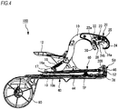
- Fig. 4 is a sectional view thereof.
- a right side of the paper surface is referred to as a front side of the binding machine for gardening 100
- a left side of the paper surface is referred to as a rear side of the binding machine for gardening 100.
- the binding machine for gardening 100 as a hand-held tool includes a clincher arm 10, a binder main body 40, a handle 12, a tape pull-out unit 20, a tape conveying unit 42, a tape cutting unit 50, a staple magazine unit 60 and a tape magazine unit 80.
- a base end of the clincher arm 10 is pivotally attached to a shaft portion 10a provided on a plate-shaped member 17 of the binder main body 40 and also is urged rearward by a tension spring 16.
- One end part of the tension spring 16 is attached to a portion of the clincher arm 10 which is located slightly below substantially the middle thereof, and the other end part of the tension spring 16 is attached to a shaft portion 16a provided on the plate-shaped member 17.
- the shaft portion 16a is arranged on a portion of the plate-shape member 17 which is located slightly more rearward than the shaft portion 10a.
- a rear end side of the handle 12 is configured as a grip portion to be gripped by a user.
- a middle part of the handle 12 is pivotally attached to the clincher arm 10 at substantially.
- a hook 12a is provided on a front end side of the handle 12.
- the hook 12a is hooked on an attaching portion 41 provided on the binder main body 40.
- the clincher arm 10 can be opened or closed relative to the binder main body 40 in accordance with an operation of opening or closing the handle 12, due to the principle of the leverage of the handle 12. Additionally, by releasing engagement of the hook 12a with the attaching portion 41, it is possible to largely open the clincher arm 10 relative to the binder main body 40. By having such a function, binding of a bound article 500 having a large diameter is allowed.
- the tape pull-out unit 20 is a mechanism configured to pull out a tape TP from the binder main body 40 and is provided on a distal end of the clincher arm 10.
- the tape pull-out unit 20 has a lock plate 22, a tape catch 24 and a tape plate 26.
- the lock plate 22 is configured to be pivotable about a shaft portion 22a as a fulcrum provided on one end side thereof.
- the other end side of the lock plate 22 is urged toward the tape catch 24 by a coil spring 23.
- the lock plate 22 When being urged by the coil spring 23, the lock plate 22 is engaged with the tape catch 24, thereby locking the tape catch 24 and thus fixing the tape catch 24 at a location spaced from the tape plate 26.
- the tape catch 24 is provided to be pivotable about a shaft portion 24a as a fulcrum and is urged toward the tape plate 26 by a torsion coil spring 25. If locking of the tape catch 24 by the locking plate 22 is released during pulling out of the tape, a tapered-shaped distal end portion 24b of the tape catch 24 is moved toward the tape plate 26 due to urging by the torsion coil spring 25.
- the tape plate 26 is arranged to be opposed to the tape catch 24 and has a distal end extending from the lock plate 22 toward the binder main body 40.
- the tape plate 26 is configured to sandwich the tape TP between the extending portion thereof and the tape catch 24 and also to pull the tape TP upward from a tape guide 46 in accordance with a return (opening) operation of the clincher arm 10.
- the tape conveying unit 42 has a tape holder 44 and the tape guide 46.
- the tape holder 44 is a path for conveying the tape from the tape magazine unit 80 to the tape guide 46 and is provided along a longitudinal direction of the binder main body 40. Also, the tape holder 44 is configured to be capable of opening and closing about one side thereof in the longitudinal direction as a fulcrum, thereby facilitating an operation of setting the tape TP therein.
- the tape guide 46 is pivotally provided on a front end of the binder main body 40 (tape holder 44) and is configured to maintain the tape with a leading end thereof pulled upward from the tape guide 46.
- the tape cutting unit 50 has a cutting blade 200 for cutting the tape TP and a lock mechanism 52 for locking and unlocking the cutting blade 200 with respect to the tape guide 46.
- the cutting blade 200 is configured to be fixed at a predetermined location on the tape guide 46 by the lock mechanism 52 and also to be removable from the tape guide 46 by releasing of the lock mechanism 52. Meanwhile, the configuration or function of the tape cutting unit 50 will be described below.
- the staple magazine unit 60 is attached on an upper surface side of the binder main body 40, and staples, which are bonded and connected to each other, are loaded therein.
- the staple magazine unit 60 is configured to drive a staple into an overlapping portion of the tape TP in accordance with the opening and closing operation of the clincher arm 10, thereby binding the overlapping portion of the tape TP.
- the tape magazine unit 80 is attached to a rear end of the binder main body 40 and receives a tape roll, which is formed by rolling the tape TP.
- the tape magazine unit 80 is configured to rotate in a forward direction by an operation of pulling out the tape TP based on the opening and closing operation of the clincher arm 10, thereby sending the tape TP to the tape conveying unit 42.
- the binding machine for gardening 100 as shown in Figs. 1 to 3 is accidently dropped during use thereof, there is a possibility that the hook 12a of the handle 12 is separated from the attaching portion 41 of the binder main body 40 and thus the clincher arm 10 is pivoted rearward and largely opened, depending on how the binding machine for gardening 100 is dropped.
- the hook 12a is unintentionally separated and thus the clincher arm 10 is opened, the clincher arm 10 strongly collides with a stopper member for restricting a degree of opening of the clincher arm 10.
- the degree of opening is restricted when the base end of the clincher arm 10 comes in contact with the shaft portion 16a provided on the rear thereof.
- elastic components 19 constructed by an elastic member such as an O-ring are mounted on locations, which are respectively located on both ends of the shaft portion 16a and are to collide with the base end of the clincher arm 10. Therefore, even if the clincher arm 10 is largely opened, the base end of the clincher arm 10 collides with the elastic components 19, thereby relieving (absorbing) an impact upon opening of the clincher arm 10 by the elastic components 19. As a result, it is possible to prevent an impact of the clincher arm 10 from being directly transferred to the shaft portion 16a, thereby preventing deformation of the staple magazine unit 60 and thus allowing staples to be smoothly replaced.
- Fig. 5 is a sectional view showing the binding machine for gardening 100 in a state where the tape TP is being pulled out.
- Fig. 6 is a sectional view showing the binding machine for gardening 100 in a state where the tape TP is being cut off.
- the clincher arm 10 is moved (lowered) in a direction approaching the binder main body 40. Therefore, the lock plate 22 is abutted against the tape guide 46 of the binder main body 40, and thus the lock plate 22 is pushed upward so that locking of the tape catch 24 by the lock plate 22 is released.
- the tape catch 24 is pivoted toward the tape plate 26, and thus the tape TP is pressed against the tape guide 46 by the distal end portion 24b of the tape catch 24.
- the clincher arm 10 is moved (lifted) in a direction away from the binder main body 40. Accordingly, as shown in Fig. 5 , the tape catch 24 is transferred from the tape guide 46 to the tape pate 26, and thus the tape TP is pulled upward from the tape guide 46 while being sandwiched between the tape plate 26 and the tape catch 24. Also, as the clincher arm 10 is lifted, the lock plate 22 and the tape catch 24 are engaged with each other.
- the tape TP is pressed against a branch of a vegetable and the like or a support (hereinafter, the branch and the support are collectively referred to as a bound article 500), and thus the bound article 500 is taken in the clincher arm 10.
- the clincher arm 10 is moved (lowered) in the direction approaching the binder main body 40, and thus the tape TP is wrapped around the bound article 500.
- the tape guide 46 is moved along opposing inclined surfaces of the tape catch 24, and then if the tape guide 46 reaches a location at which movement thereof is limited, the tape catch 24 is pivoted in a direction away from the tape plate 26 (toward the front side). Accordingly, the tape guide 46 is also pivoted toward the front side.
- the cutting blade 200 is also pivoted so that teeth, which are provided on a distal end thereof, pierce through the tape TP, thereby cutting the tape TP.
- a clincher 30 presses a staple magazine main body 62, and thus the staple magazine main body 62 is tilted about a rear end thereof as a fulcrum.
- a staple is pushed out though an exit portion by a driver 78 and thus an overlapping portion of the tape TP is bound by the staple.
- an operation of binding the bound article 500 is performed by such a series of steps.
- Fig. 7 is a perspective view showing an example of a configuration of the tape cutting unit 50 and Fig. 8 is a sectional view thereof. As shown in Figs. 7 and 8 , the tape cutting unit 50 has the cutting blade 200 and the lock mechanism 52.
- the lock mechanism 52 is a mechanism configured to lock the cutting blade 200 at a predetermined location on the tape guide 46 or to unlock the cutting blade 200.
- the lock mechanism 52 has a release button 54, a coil spring 56 and a guide member 58.
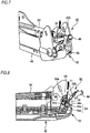
- the release button 54 is arranged on a front surface portion of the tape guide 46, but at a location where the release button 54 does not overlap with an extracting direction D1 of the cutting blade 200 (location shifted therefrom) (see Figs. 7 and 8 ).
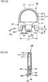
- Fig. 9A is a front view showing an example of a configuration of the release button 54 and
- Fig. 9B is a plan view thereof.
- the release button 54 is a cylindrical body 54a and an enlarged diameter portion 54b integrally formed with a rear end (base end) of the cylindrical body 54a and having a diameter X2 larger than a diameter X1 of the cylindrical body 54a.
- the cylindrical body 54a of the release button 54 is provided to protrude forward through a through-hole 46a formed in the tape guide 46, and the enlarged diameter portion 54b of the release button 54 is locked by an opening peripheral edge portion of the through-hole 46a. Therefore, the release button 54 is prevented from falling out forward from the tape guide 46.
- the guide member 58 is a member intended to assist in attaching the cutting blade 200 and is attached to a portion of the binder main body 40 which is located on the rear of the cutting blade 200. Also, a shaft portion 58a extending in a transversal direction of the binder main body 40 is provided adjacent to the guide member 58. The coil spring 56 is mounted on the shaft portion 58a.
- the coil spring 56 is constructed by a so-called double torsion spring in which two torsion springs are connected with each other.
- the coil spring 56 is configured to be abutted against the enlarged diameter portion 54b of the release button 54 and thus to urge the release button 54 forward, thereby elastically supporting the release button 54 while forcing the release button 54 to protrude forward through the tape guide 46.
- the coil spring 56 is employed as an urging means for the release button 54, the present invention is not limited thereto, but an elastic member such as a leaf spring or a compression spring may be employed.
- Fig. 10A is a perspective view showing an example of a configuration of the cutting blade 200 and Fig. 10B is a plan view thereof.
- the cutting blade 200 has a main body 210 having a generally rectangular shape as viewed in a plan view, a recess 220 provided in a base end of the main body 210, and sawtooth-shaped teeth 230 provided on a distal end of the main body.
- the recess 220 is formed to be cut out in a generally circular shape corresponding to a shape of the release button 54.
- a width Y1 of the recess 220 is selected to have substantially the same length as the diameter X2 of the enlarged diameter portion 54b of the release button 54.
- a width Y2 of the recess 220 is selected to be larger than the diameter X1 of the cylindrical body 54a of the release button 54.
- the base end of the main body 210 is configured such that a lower portion than the vicinity of the middle thereof is formed to have a narrower width (hereinafter, referred to as a narrower portion 212) and an upper portion is formed to have a wider width (hereinafter, referred to as a wider portion 214).
- a dimension of the narrower portion 212 in a width direction thereof is a width Y4, and a dimension of the wider portion 214 in a width direction thereof is a width Y3 wider than the width Y4. Also, a dimension of the wider portion 214 in a length direction thereof, which ranges from a tooth tip to a lower end of the wider portion, is a length Y5.
- tapered surfaces 216, 218 for picking-up are respectively formed on both sides of a lower end of the main body 210, thereby facilitating attaching the cutting blade 200 to the binder main body 40.
- Fig. 11 is a perspective view showing an example of a configuration of the cap 300 according to one embodiment of the present invention.
- Fig. 12A is a plan view showing the configuration example of the cap 300 and Fig. 12B is a sectional view taken along a line A-A in the cap 300 as shown in Fig. 12A .
- Fig. 13A is a bottom view showing the configuration example of the cap 300 and Fig. 13B is a side view thereof.
- a downward direction on the paper surface is referred to as an extracting direction D2 in which the cutting blade 200 is extracted from the cap 300, and a upward direction on the paper surface is referred to as a mounting direction D3 in which the cutting blade 200 is loaded into the cap 300.
- the cap 300 is a member intended to hold the cutting blade 200 in a stable posture during replacing of the cutting blade 200 and also to protect the teeth 230 of the cutting blade 200 (see Fig. 10A ).
- the cap 300 has a grip portion 310 and a cutting blade holding portion (holding portion) 320.
- the grip portion 310 has, for example, a flat and generally half-circular shape as viewed in a plan view, namely a generally semi-cylindrical shape and is formed to have an external appearance larger than an average thumb size of general users.
- the grip portion 310 has a flat surface portion 312 and an edge portion 314 connected to the flat surface portion 312 via a step 313 and formed along a peripheral edge portion of the flat surface portion 312. Therefore, since the edge portion 314 formed by the step 313 serves as a slip stopper, a user can perform an operation of replacing the cutting blade 200 while securely gripping the cap 300.
- the cutting blade holding portion 320 is integrally formed with an end portion 317 of the grip portion 310 facing a direction (direction in which the cutting blade 200 is mounted) opposite to an end portion 316 thereof facing a direction in which gripping fingers of the user extend and is configured to hold the teeth of the cutting blade 200 while causing the teeth to face the grip portion 310.
- the cutting blade holding portion 320 has a blade edge protection portion 330, a side surface guide portion 340, 342, a first support portion (support portion) 350, and a second support portion 360.
- the blade edge protection portion 330 is a portion configured to prevent the teeth 230 of the cutting blade 200 from coming in contact with a hand of the user or any parts of the binder main body 40 during replacing of the cutting blade 200.
- the blade edge protection portion 330 includes a tooth abutting portion 330a and tooth fitting portions 330b.
- the tooth abutting portion 330a is configured by an end surface provided on the end portion 317 of the grip portion 310 and is configured to allow the teeth 230 of the mounted cutting blade 200 to be abutted thereagainst.
- a thickness of the end surface portion is configured to be thicker than a blade thickness of the cutting blade 200, so that the teeth 230 of the cutting blade 200 can be protected without being exposed to the outside.
- the tooth fitting portions 330b are configured to protrude from the end surface of the tooth abutting portion 330a as described above and also to have a convex shape corresponding to the saw-shaped teeth 230 of the cutting blade 200, so that when the cutting blade 200 is mounted on the cap 300, the teeth 230 are engaged (fitted) therebetween.
- the side guide portions 340, 342 are respectively provided to extend from widthwise side ends of the end portion 317 of the grip portion 310 by a predetermined length in the extracting direction D2. That is, the side guide portions 340,342 extend from locations, which correspond to the side surface portion of the cutting blade 200 to be mounted, along the extracting direction D2.
- a distance Z1 between inner wall surfaces of the side guide portions 340, 342 is set to be substantially the same as the width Y3 of the cutting blade 200.
- Each of the inner surfaces of the side guide portions 340, 342 is configured by a flat surface and is configured to slidably support the respective side surface portions of the cutting blade 200 when the cutting blade 200 is mounted on or removed from the cap 300.
- a length Z2 of the side guide portions 340,342 in a length direction thereof is set, for example, to a length ranging from a distal end of the cutting blade 200 to substantially the middle thereof, so that a posture of the mounted cutting blade 200 can be stabilized.
- the first support portion 350 is provided to extend from a portion of the end portion 317 of the grip portion 310, which corresponds to the middle portion thereof in a width direction and also is located on an upper side thereof in a thickness direction, by a predetermined length in the extracting direction D2. That is, the first support portion 350 extends from the end portion 317 of the grip portion 310 toward the cutting blade 200 to be mounted on the cap 300.
- the first support portion 350 serves as a leaf spring and is configured to elastically support a front surface (first surface) of the cutting blade 200 by a first protrusion 350a provided on an inner side of a distal end thereof. Also, a second protrusion 350b is provided on an outer side of the distal end of the first support portion 350.
- the second protrusion 350b serves as a positioning portion when the cutting blade 200 is mounted at a mounting location on the binder main body 40, and is provided to be fitted into a recess 59 (see Fig. 15A and the like) serving as an aligning portion provided at a loading location on the binder main body 40 as described below.
- the second support portion 360 is provided to extend in the extracting direction D2 from a portion of the end portion 317 of the grip portion 310, which is located on a lower side thereof in the thickness direction, and is configured to support a back surface of the cutting blade 200 mounted on the cap 300.
- the second support portion 360 is formed to have a shape along the tooth abutting portion 330a and the side guide portions 340, 342.
- Fig. 14A is a perspective view showing an example of a configuration of the cap unit 400 and Fig. 14B is a plan view thereof.
- the cap unit 400 is constituted of the cap 300 and the cutting blade 200 mounted on the cap 300.
- the teeth 230 of the cutting blade 200 are protected while being engaged with the toot fitting portions 330b of the cap 300 and also being abutted against the toot abutting portion 330a. Also, the front and back surfaces of the cutting blade 200 are sandwiched and supported by the first support portion 350 and the second support portion 360. The side surface portions 210a, 210b of the cutting blade 200 are respectively supported by the side guide portions 340, 342. Therefore, when the cutting blade 200 is mounted on the cap 300, movement of the cutting blade 200 in the upward and downward direction and also the width direction can be restricted, and as a result, the cutting blade 200 can be held in a stable posture by the cap 300.
- Fig. 15A is a perspective view explaining a state before the cutting blade 200 is loaded in the binder main body 40
- Fig. 15B is a sectional view thereof
- Fig. 16A is a perspective view explaining a state when the cutting blade 200 is loaded in a loading location on the binding machine for gardening 100
- Fig. 16B is a sectional view thereof
- Fig. 17A is a perspective view explaining a state after the cutting blade 200 is loaded in the loading location on the binding machine for gardening 100
- Fig. 17B is a sectional view thereof.
- a user prepares the cap unit 400 and then grips the grip portion 310 of the cap 300 with a thumb and an index finger of one hand. Subsequently, the user pivots and opens the tape guide 46 outward while pushing the release button 54 of the lock mechanism 52 with the other hand.
- the user moves the gripped cap unit 400 toward the binding machine for gardening 100 while causing the recess 220 of the cutting blade 200 (see Fig. 10A ) to face the binding machine for gardening 100, thereby fitting the first protrusion 350a of the first support portion 350 of the cap 300 into the recess 59 provided on the binding machine for gardening 100. Accordingly, the recess 220 of the cutting blade 200 is fitted onto the release button 54 of the lock mechanism 52. Subsequently, the user releases the other hand from the release button 54, and as a result, the cutting blade 200 is locked by the lock mechanism 52.
- Figs. 17A and 17B the user pulls outward the cap 300 gripped with the one hand, thereby removing the cap 300 from the cutting blade 200.
- an operation of replacing the cutting blade 200 is performed by such a series of steps.
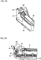
- Fig. 18A is a perspective view showing a state of the lock mechanism 52 when the release button 54 is not pushed and Fig. 18B is a perspective view showing a state of the lock mechanism 52 when the release button 54 is pushed.
- Fig. 19A is a perspective view showing the state when the release button 54 is not pushed, as viewed from the rear side of the lock mechanism 52, and Fig. 19B is a plan view thereof.
- Fig. 20A is a perspective view showing a state when the cutting blade 200 is unlocked and removed, as viewed from the rear side of the lock mechanism 52, and Fig. 20B is a plan view thereof.
- the release button 54 As shown in Figs. 18B , 20A and 20B , if the release button 54 is pushed by the user, the release button 54 is moved rearward against an urging force of the coil spring 56. Therefore, the cylindrical body 54a of the release button 54, which has the diameter X1 smaller than the width Y2 of the recess 220 of the cutting blade 200, is positioned in the recess 220, and thus locking of the cutting blade 200 by the release button 54 is released. In this state, if the cutting blade 200 is pulled outward, the recess 220 of the cutting blade 200 can escape from the release button 54, and as a result, the cutting blade 200 can be removed from the binder main body 40.
- the cutting blade 200 is held by the cap 300 and thus a posture of the cutting blade 200 can be stabilized. That is, in the related art, the cutting blade 200 is gripped with a needle nose pliers or the like and thus the cutting blade 200 is likely to be misaligned with the respect to the needle nose pliers. However, the problem of misalignment can be solved by using the cap 300. Therefore, it is possible to precisely load the cutting blade 200 at a loading location on the binder main body 40.
- the teeth 230 on the distal end of the cutting blade 200 are protected by the cap 300. Therefore, it is possible to prevent the teeth 230 of the cutting blade 200 from coming in contact with any parts constituting the binding machine for gardening 100 or a hand of a user during replacing of the cutting blade 200.
- the cutting blade 200 can be held at a fixed position (in an immovable state) by the cap 300 and thus can be strongly pushed into the loading location on the binder main body 40. Therefore, it is possible to facilitate loading the cutting blade 200 into the loading location on the binder main body 40. As a result, the cutting blade 200 can be loaded into the loading without damaging the teeth 230.
- the cap 300 is removed after the cutting blade 200 is loaded in the loading location on the binder main body 40.
- the lock mechanism 52 is activated. Therefore, the cutting blade 200 is not removed from the binder main body 40, but the cap 300 only is removed.
- the cutting blade 200 is also removed together with the cap 300. Therefore, it is possible to identify whether or not the cutting blade 200 is precisely loaded in the loading location, depending on whether or not the cutting blade 200 is mounted on the removed cap 300.
Landscapes
- Life Sciences & Earth Sciences (AREA)
- Environmental Sciences (AREA)
- Botany (AREA)
- Engineering & Computer Science (AREA)
- Mechanical Engineering (AREA)
- Basic Packing Technique (AREA)
- Supports For Plants (AREA)
- Auxiliary Apparatuses For Manual Packaging Operations (AREA)
Abstract
Description
- The present invention relates to a cap and a cap unit.
- Conventionally, when a vine or branch of a fruit tree, a vegetable or the like is bound to a support, or vegetables or bags are bundled with each other, binding machines for gardening are widely used. In the binding machines for gardening, a binding process is performed by a series of steps as follows. First, a tape is pulled out from a binder main body by an opening and closing operation of a clincher arm, so that the tape is stretched between distal ends of the clincher arm and the binder main body. Then, in this state, the binder main body is reached out forward, so that the tape is wrapped around an object to be bounded. Then, the clincher arm is again closed, so that the tape is bounded by a staple and also the tape is cut by a cutting blade.
- For example, in
JP 2003-341613 (A - However, the binding machine for gardening described in
JP 2003-341613 (A - Accordingly, the present invention has been made keeping in mind the above problems, and an object thereof is to provide a cap and a cap unit, in which it is possible to precisely and easily replace a cutting blade.
- A cap of the present invention may be removably attached to a cutting blade configured to cut a tape. The cap may include a grip portion to be gripped by a user and a holding portion configured to hold teeth provided on a distal end of the cutting blade while causing the teeth to face the grip portion.
- A cap unit of the present invention may include a cutting blade configured to cut a tape and a cap to be removably attached to the cutting blade. The cap includes a grip portion to be gripped by a user and a holding portion configured to hold teeth provided on a distal end of the cutting blade while causing the teeth to face the grip portion.
- According to the present invention, the cutting blade is held by the cap. Therefore, during replacing of the cutting blade, it is possible to stabilize a posture of the cutting blade and also to prevent the teeth from coming in contact with parts of a binding machine for gardening.
-
-
Fig. 1 is a perspective view showing a configuration example of a binding machine for gardening according to one embodiment of the present invention. -
Fig. 2 is a first front view showing the configuration example of the binding machine for gardening. -
Fig. 3 is a second front view showing the configuration example of the binding machine for gardening. -
Fig. 4 is a sectional view showing the configuration example of the binding machine for gardening. -
Fig. 5 is a sectional view showing the binding machine for gardening in a state where a tape is being pulled out. -
Fig. 6 is a sectional view showing the binding machine for gardening in a state where the tape is being cut off. -
Fig. 7 is a perspective view showing a configuration example of a tape cutting unit. -
Fig. 8 is a sectional view showing the configuration example of the tape cutting unit. -
Fig. 9A is a front view showing a configuration example of a release button andFig. 9B is a sectional view thereof. -
Fig. 10A is a perspective view showing a configuration example of a cutting blade andFig. 10B is a plan view thereof. -
Fig. 11 is a perspective view showing a configuration example of a cap. -
Fig. 12A is a plan view showing the configuration example of the cap andFig. 12B is a sectional view taken along a line A-A inFig. 12A . -
Fig. 13A is a bottom view showing the configuration example of the cap andFig. 13B is a side view thereof. -
Fig. 14A is a perspective view showing a configuration example of a cap unit andFig. 14B is a plan view thereof. -
Fig. 15A is a perspective view explaining a state before the cutting blade is loaded in a binder main body, andFig. 15B is a sectional view thereof. -
Fig. 16A is a perspective view explaining a state when the cutting blade is loaded in a loading location on the binding machine for gardening, andFig. 16B is a sectional view thereof. -
Fig. 17A is a perspective view explaining a state after the cutting blade is loaded in the loading location on the binding machine for gardening, andFig. 17B is a sectional view thereof. -
Figs. 18A and 18B are views showing operation examples of a lock mechanism depending on whether or not the release button is pushed. -
Figs. 19A and 19B are views showing an operation example of the lock mechanism when the release button is not pushed. -
Figs. 20A and 20B are views showing an operation example of the lock mechanism when the release button is pushed. - Hereinafter, preferable embodiments of the present invention will be described in detail with reference to the accompanying drawings.
-
Fig. 1 is a perspective view showing an example of a configuration of a binding machine for gardening 100 according to a first embodiment,Figs. 2 and3 are front views thereof, andFig. 4 is a sectional view thereof. InFigs. 1 to 4 , a right side of the paper surface is referred to as a front side of the binding machine for gardening 100 and a left side of the paper surface is referred to as a rear side of the binding machine forgardening 100. - As shown in
Figs. 1 to 4 , the binding machine for gardening 100 as a hand-held tool includes aclincher arm 10, a bindermain body 40, ahandle 12, a tape pull-outunit 20, atape conveying unit 42, atape cutting unit 50, astaple magazine unit 60 and atape magazine unit 80. - A base end of the
clincher arm 10 is pivotally attached to ashaft portion 10a provided on a plate-shapedmember 17 of the bindermain body 40 and also is urged rearward by atension spring 16. One end part of thetension spring 16 is attached to a portion of theclincher arm 10 which is located slightly below substantially the middle thereof, and the other end part of thetension spring 16 is attached to ashaft portion 16a provided on the plate-shapedmember 17. Theshaft portion 16a is arranged on a portion of the plate-shape member 17 which is located slightly more rearward than theshaft portion 10a. - A rear end side of the
handle 12 is configured as a grip portion to be gripped by a user. A middle part of thehandle 12 is pivotally attached to theclincher arm 10 at substantially. Ahook 12a is provided on a front end side of thehandle 12. Thehook 12a is hooked on an attachingportion 41 provided on the bindermain body 40. According to this configuration, theclincher arm 10 can be opened or closed relative to the bindermain body 40 in accordance with an operation of opening or closing thehandle 12, due to the principle of the leverage of thehandle 12. Additionally, by releasing engagement of thehook 12a with the attachingportion 41, it is possible to largely open theclincher arm 10 relative to the bindermain body 40. By having such a function, binding of abound article 500 having a large diameter is allowed. - The tape pull-out
unit 20 is a mechanism configured to pull out a tape TP from the bindermain body 40 and is provided on a distal end of theclincher arm 10. The tape pull-outunit 20 has alock plate 22, atape catch 24 and atape plate 26. - The
lock plate 22 is configured to be pivotable about ashaft portion 22a as a fulcrum provided on one end side thereof. The other end side of thelock plate 22 is urged toward thetape catch 24 by acoil spring 23. When being urged by thecoil spring 23, thelock plate 22 is engaged with thetape catch 24, thereby locking thetape catch 24 and thus fixing thetape catch 24 at a location spaced from thetape plate 26. - The
tape catch 24 is provided to be pivotable about ashaft portion 24a as a fulcrum and is urged toward thetape plate 26 by atorsion coil spring 25. If locking of thetape catch 24 by the lockingplate 22 is released during pulling out of the tape, a tapered-shapeddistal end portion 24b of thetape catch 24 is moved toward thetape plate 26 due to urging by thetorsion coil spring 25. - The
tape plate 26 is arranged to be opposed to thetape catch 24 and has a distal end extending from thelock plate 22 toward the bindermain body 40. Thetape plate 26 is configured to sandwich the tape TP between the extending portion thereof and thetape catch 24 and also to pull the tape TP upward from atape guide 46 in accordance with a return (opening) operation of theclincher arm 10. - The
tape conveying unit 42 has atape holder 44 and thetape guide 46. Thetape holder 44 is a path for conveying the tape from thetape magazine unit 80 to thetape guide 46 and is provided along a longitudinal direction of the bindermain body 40. Also, thetape holder 44 is configured to be capable of opening and closing about one side thereof in the longitudinal direction as a fulcrum, thereby facilitating an operation of setting the tape TP therein. Thetape guide 46 is pivotally provided on a front end of the binder main body 40 (tape holder 44) and is configured to maintain the tape with a leading end thereof pulled upward from thetape guide 46. - The
tape cutting unit 50 has acutting blade 200 for cutting the tape TP and alock mechanism 52 for locking and unlocking thecutting blade 200 with respect to thetape guide 46. Thecutting blade 200 is configured to be fixed at a predetermined location on thetape guide 46 by thelock mechanism 52 and also to be removable from thetape guide 46 by releasing of thelock mechanism 52. Meanwhile, the configuration or function of thetape cutting unit 50 will be described below. - The
staple magazine unit 60 is attached on an upper surface side of the bindermain body 40, and staples, which are bonded and connected to each other, are loaded therein. Thestaple magazine unit 60 is configured to drive a staple into an overlapping portion of the tape TP in accordance with the opening and closing operation of theclincher arm 10, thereby binding the overlapping portion of the tape TP. - The
tape magazine unit 80 is attached to a rear end of the bindermain body 40 and receives a tape roll, which is formed by rolling the tape TP. Thetape magazine unit 80 is configured to rotate in a forward direction by an operation of pulling out the tape TP based on the opening and closing operation of theclincher arm 10, thereby sending the tape TP to thetape conveying unit 42. - Herein, when the binding machine for gardening 100 as shown in
Figs. 1 to 3 is accidently dropped during use thereof, there is a possibility that thehook 12a of thehandle 12 is separated from the attachingportion 41 of the bindermain body 40 and thus theclincher arm 10 is pivoted rearward and largely opened, depending on how the binding machine for gardening 100 is dropped. In this way, when thehook 12a is unintentionally separated and thus theclincher arm 10 is opened, theclincher arm 10 strongly collides with a stopper member for restricting a degree of opening of theclincher arm 10. In the present embodiment, the degree of opening is restricted when the base end of theclincher arm 10 comes in contact with theshaft portion 16a provided on the rear thereof. Therefore, theshaft portion 16a or the plate-shapedmember 17 is deformed due to collision between theclincher arm 10 and theshaft portion 16a. As a result, there is a problem that a lid of thestaple magazine unit 60 is not opened and thus replacement of the staples is impossible. - Accordingly, in the present embodiment,
elastic components 19 constructed by an elastic member such as an O-ring are mounted on locations, which are respectively located on both ends of theshaft portion 16a and are to collide with the base end of theclincher arm 10. Therefore, even if theclincher arm 10 is largely opened, the base end of theclincher arm 10 collides with theelastic components 19, thereby relieving (absorbing) an impact upon opening of theclincher arm 10 by theelastic components 19. As a result, it is possible to prevent an impact of theclincher arm 10 from being directly transferred to theshaft portion 16a, thereby preventing deformation of thestaple magazine unit 60 and thus allowing staples to be smoothly replaced. - Next, an example of an operation of the binding machine for gardening 100 according to the present invention during a binding process will be described.
Fig. 5 is a sectional view showing the binding machine for gardening 100 in a state where the tape TP is being pulled out.Fig. 6 is a sectional view showing the binding machine for gardening 100 in a state where the tape TP is being cut off. - Referring to
Figs. 1 to 6 , if thehandle 12 is gripped by a user, theclincher arm 10 is moved (lowered) in a direction approaching the bindermain body 40. Therefore, thelock plate 22 is abutted against thetape guide 46 of the bindermain body 40, and thus thelock plate 22 is pushed upward so that locking of thetape catch 24 by thelock plate 22 is released. - If locking of the
tape catch 24 is released, thetape catch 24 is pivoted toward thetape plate 26, and thus the tape TP is pressed against thetape guide 46 by thedistal end portion 24b of thetape catch 24. - Subsequently, if gripping of the
handle 12 by the user is released, theclincher arm 10 is moved (lifted) in a direction away from the bindermain body 40. Accordingly, as shown inFig. 5 , thetape catch 24 is transferred from thetape guide 46 to thetape pate 26, and thus the tape TP is pulled upward from thetape guide 46 while being sandwiched between thetape plate 26 and thetape catch 24. Also, as theclincher arm 10 is lifted, thelock plate 22 and thetape catch 24 are engaged with each other. - Subsequently, as the binder
main body 40 is reached out forward, the tape TP is pressed against a branch of a vegetable and the like or a support (hereinafter, the branch and the support are collectively referred to as a bound article 500), and thus thebound article 500 is taken in theclincher arm 10. - Subsequently, if the
handle 12 is again strongly gripped by the user, theclincher arm 10 is moved (lowered) in the direction approaching the bindermain body 40, and thus the tape TP is wrapped around the boundarticle 500. - As the
clincher arm 10 is lowered, thetape guide 46 is moved along opposing inclined surfaces of thetape catch 24, and then if thetape guide 46 reaches a location at which movement thereof is limited, thetape catch 24 is pivoted in a direction away from the tape plate 26 (toward the front side). Accordingly, thetape guide 46 is also pivoted toward the front side. - As the
tape guide 46 is pivoted, as shown inFig. 6 , thecutting blade 200 is also pivoted so that teeth, which are provided on a distal end thereof, pierce through the tape TP, thereby cutting the tape TP. Also, aclincher 30 presses a staple magazine main body 62, and thus the staple magazine main body 62 is tilted about a rear end thereof as a fulcrum. As a result, a staple is pushed out though an exit portion by adriver 78 and thus an overlapping portion of the tape TP is bound by the staple. In the present embodiment, an operation of binding thebound article 500 is performed by such a series of steps. - Next, the
tape cutting unit 50 will be described.Fig. 7 is a perspective view showing an example of a configuration of thetape cutting unit 50 andFig. 8 is a sectional view thereof. As shown inFigs. 7 and 8 , thetape cutting unit 50 has thecutting blade 200 and thelock mechanism 52. - First, the
lock mechanism 52 will be described. Thelock mechanism 52 is a mechanism configured to lock thecutting blade 200 at a predetermined location on thetape guide 46 or to unlock thecutting blade 200. Thelock mechanism 52 has arelease button 54, acoil spring 56 and aguide member 58. - The
release button 54 is arranged on a front surface portion of thetape guide 46, but at a location where therelease button 54 does not overlap with an extracting direction D1 of the cutting blade 200 (location shifted therefrom) (seeFigs. 7 and 8 ).Fig. 9A is a front view showing an example of a configuration of therelease button 54 andFig. 9B is a plan view thereof. As shown inFigs. 7, 8 ,9A and 9B , therelease button 54 is acylindrical body 54a and anenlarged diameter portion 54b integrally formed with a rear end (base end) of thecylindrical body 54a and having a diameter X2 larger than a diameter X1 of thecylindrical body 54a. Thecylindrical body 54a of therelease button 54 is provided to protrude forward through a through-hole 46a formed in thetape guide 46, and theenlarged diameter portion 54b of therelease button 54 is locked by an opening peripheral edge portion of the through-hole 46a. Therefore, therelease button 54 is prevented from falling out forward from thetape guide 46. - The
guide member 58 is a member intended to assist in attaching thecutting blade 200 and is attached to a portion of the bindermain body 40 which is located on the rear of thecutting blade 200. Also, ashaft portion 58a extending in a transversal direction of the bindermain body 40 is provided adjacent to theguide member 58. Thecoil spring 56 is mounted on theshaft portion 58a. - The
coil spring 56 is constructed by a so-called double torsion spring in which two torsion springs are connected with each other. Thecoil spring 56 is configured to be abutted against theenlarged diameter portion 54b of therelease button 54 and thus to urge therelease button 54 forward, thereby elastically supporting therelease button 54 while forcing therelease button 54 to protrude forward through thetape guide 46. Meanwhile, although in the present embodiment, thecoil spring 56 is employed as an urging means for therelease button 54, the present invention is not limited thereto, but an elastic member such as a leaf spring or a compression spring may be employed. - Next, the
cutting blade 200 will be described.Fig. 10A is a perspective view showing an example of a configuration of thecutting blade 200 andFig. 10B is a plan view thereof. As shown inFigs. 10A and 10B , thecutting blade 200 has amain body 210 having a generally rectangular shape as viewed in a plan view, arecess 220 provided in a base end of themain body 210, and sawtooth-shapedteeth 230 provided on a distal end of the main body. Therecess 220 is formed to be cut out in a generally circular shape corresponding to a shape of therelease button 54. A width Y1 of therecess 220 is selected to have substantially the same length as the diameter X2 of theenlarged diameter portion 54b of therelease button 54. A width Y2 of therecess 220 is selected to be larger than the diameter X1 of thecylindrical body 54a of therelease button 54. Also, the base end of themain body 210 is configured such that a lower portion than the vicinity of the middle thereof is formed to have a narrower width (hereinafter, referred to as a narrower portion 212) and an upper portion is formed to have a wider width (hereinafter, referred to as a wider portion 214). A dimension of thenarrower portion 212 in a width direction thereof is a width Y4, and a dimension of thewider portion 214 in a width direction thereof is a width Y3 wider than the width Y4. Also, a dimension of thewider portion 214 in a length direction thereof, which ranges from a tooth tip to a lower end of the wider portion, is a length Y5. When thecutting blade 200 is attached such that a lower surface of thewider surface 214 is in contact with the main body, it is possible to maintain an amount of protrusion of thecutting blade 200 constant. Also, taperedsurfaces main body 210, thereby facilitating attaching thecutting blade 200 to the bindermain body 40. - Next, a
cap 300 will be described.Fig. 11 is a perspective view showing an example of a configuration of thecap 300 according to one embodiment of the present invention.Fig. 12A is a plan view showing the configuration example of thecap 300 andFig. 12B is a sectional view taken along a line A-A in thecap 300 as shown inFig. 12A .Fig. 13A is a bottom view showing the configuration example of thecap 300 andFig. 13B is a side view thereof. InFig. 11 , a downward direction on the paper surface is referred to as an extracting direction D2 in which thecutting blade 200 is extracted from thecap 300, and a upward direction on the paper surface is referred to as a mounting direction D3 in which thecutting blade 200 is loaded into thecap 300. - As shown in
Figs. 11 to 13 , thecap 300 is a member intended to hold thecutting blade 200 in a stable posture during replacing of thecutting blade 200 and also to protect theteeth 230 of the cutting blade 200 (seeFig. 10A ). Thecap 300 has agrip portion 310 and a cutting blade holding portion (holding portion) 320. - The
grip portion 310 has, for example, a flat and generally half-circular shape as viewed in a plan view, namely a generally semi-cylindrical shape and is formed to have an external appearance larger than an average thumb size of general users. Thegrip portion 310 has aflat surface portion 312 and anedge portion 314 connected to theflat surface portion 312 via astep 313 and formed along a peripheral edge portion of theflat surface portion 312. Therefore, since theedge portion 314 formed by thestep 313 serves as a slip stopper, a user can perform an operation of replacing thecutting blade 200 while securely gripping thecap 300. - The cutting
blade holding portion 320 is integrally formed with anend portion 317 of thegrip portion 310 facing a direction (direction in which thecutting blade 200 is mounted) opposite to anend portion 316 thereof facing a direction in which gripping fingers of the user extend and is configured to hold the teeth of thecutting blade 200 while causing the teeth to face thegrip portion 310. The cuttingblade holding portion 320 has a bladeedge protection portion 330, a sidesurface guide portion second support portion 360. - The blade
edge protection portion 330 is a portion configured to prevent theteeth 230 of thecutting blade 200 from coming in contact with a hand of the user or any parts of the bindermain body 40 during replacing of thecutting blade 200. The bladeedge protection portion 330 includes atooth abutting portion 330a and toothfitting portions 330b. Thetooth abutting portion 330a is configured by an end surface provided on theend portion 317 of thegrip portion 310 and is configured to allow theteeth 230 of the mountedcutting blade 200 to be abutted thereagainst. A thickness of the end surface portion is configured to be thicker than a blade thickness of thecutting blade 200, so that theteeth 230 of thecutting blade 200 can be protected without being exposed to the outside. The toothfitting portions 330b are configured to protrude from the end surface of thetooth abutting portion 330a as described above and also to have a convex shape corresponding to the saw-shapedteeth 230 of thecutting blade 200, so that when thecutting blade 200 is mounted on thecap 300, theteeth 230 are engaged (fitted) therebetween. - The
side guide portions end portion 317 of thegrip portion 310 by a predetermined length in the extracting direction D2. That is, the side guide portions 340,342 extend from locations, which correspond to the side surface portion of thecutting blade 200 to be mounted, along the extracting direction D2. A distance Z1 between inner wall surfaces of theside guide portions cutting blade 200. Each of the inner surfaces of theside guide portions cutting blade 200 when thecutting blade 200 is mounted on or removed from thecap 300. A length Z2 of the side guide portions 340,342 in a length direction thereof is set, for example, to a length ranging from a distal end of thecutting blade 200 to substantially the middle thereof, so that a posture of the mountedcutting blade 200 can be stabilized. - The
first support portion 350 is provided to extend from a portion of theend portion 317 of thegrip portion 310, which corresponds to the middle portion thereof in a width direction and also is located on an upper side thereof in a thickness direction, by a predetermined length in the extracting direction D2. That is, thefirst support portion 350 extends from theend portion 317 of thegrip portion 310 toward thecutting blade 200 to be mounted on thecap 300. Thefirst support portion 350 serves as a leaf spring and is configured to elastically support a front surface (first surface) of thecutting blade 200 by afirst protrusion 350a provided on an inner side of a distal end thereof. Also, asecond protrusion 350b is provided on an outer side of the distal end of thefirst support portion 350. Thesecond protrusion 350b serves as a positioning portion when thecutting blade 200 is mounted at a mounting location on the bindermain body 40, and is provided to be fitted into a recess 59 (seeFig. 15A and the like) serving as an aligning portion provided at a loading location on the bindermain body 40 as described below. - The
second support portion 360 is provided to extend in the extracting direction D2 from a portion of theend portion 317 of thegrip portion 310, which is located on a lower side thereof in the thickness direction, and is configured to support a back surface of thecutting blade 200 mounted on thecap 300. In the present embodiment, thesecond support portion 360 is formed to have a shape along thetooth abutting portion 330a and theside guide portions - Next, a
cap unit 400 will be described.Fig. 14A is a perspective view showing an example of a configuration of thecap unit 400 andFig. 14B is a plan view thereof. As shown inFigs. 14A and 14B , thecap unit 400 is constituted of thecap 300 and thecutting blade 200 mounted on thecap 300. - The
teeth 230 of thecutting blade 200 are protected while being engaged with thetoot fitting portions 330b of thecap 300 and also being abutted against thetoot abutting portion 330a. Also, the front and back surfaces of thecutting blade 200 are sandwiched and supported by thefirst support portion 350 and thesecond support portion 360. Theside surface portions cutting blade 200 are respectively supported by theside guide portions cutting blade 200 is mounted on thecap 300, movement of thecutting blade 200 in the upward and downward direction and also the width direction can be restricted, and as a result, thecutting blade 200 can be held in a stable posture by thecap 300. - Next, replacing the
cutting blade 200 will be described.Fig. 15A is a perspective view explaining a state before thecutting blade 200 is loaded in the bindermain body 40, andFig. 15B is a sectional view thereof.Fig. 16A is a perspective view explaining a state when thecutting blade 200 is loaded in a loading location on the binding machine for gardening 100, andFig. 16B is a sectional view thereof.Fig. 17A is a perspective view explaining a state after thecutting blade 200 is loaded in the loading location on the binding machine for gardening 100, andFig. 17B is a sectional view thereof. - As shown in
Figs. 15A and 15B , a user prepares thecap unit 400 and then grips thegrip portion 310 of thecap 300 with a thumb and an index finger of one hand. Subsequently, the user pivots and opens thetape guide 46 outward while pushing therelease button 54 of thelock mechanism 52 with the other hand. - Then, as shown in
Figs. 16A and 16B , the user moves the grippedcap unit 400 toward the binding machine for gardening 100 while causing therecess 220 of the cutting blade 200 (seeFig. 10A ) to face the binding machine for gardening 100, thereby fitting thefirst protrusion 350a of thefirst support portion 350 of thecap 300 into therecess 59 provided on the binding machine forgardening 100. Accordingly, therecess 220 of thecutting blade 200 is fitted onto therelease button 54 of thelock mechanism 52. Subsequently, the user releases the other hand from therelease button 54, and as a result, thecutting blade 200 is locked by thelock mechanism 52. - Then, as shown in
Figs. 17A and 17B , the user pulls outward thecap 300 gripped with the one hand, thereby removing thecap 300 from thecutting blade 200. In the present embodiment, an operation of replacing thecutting blade 200 is performed by such a series of steps. - Next, an example of an operation of the
lock mechanism 52 when locking and unlocking thecutting blade 200 with respect to the bindermain body 40 will be described.Fig. 18A is a perspective view showing a state of thelock mechanism 52 when therelease button 54 is not pushed andFig. 18B is a perspective view showing a state of thelock mechanism 52 when therelease button 54 is pushed.Fig. 19A is a perspective view showing the state when therelease button 54 is not pushed, as viewed from the rear side of thelock mechanism 52, andFig. 19B is a plan view thereof.Fig. 20A is a perspective view showing a state when thecutting blade 200 is unlocked and removed, as viewed from the rear side of thelock mechanism 52, andFig. 20B is a plan view thereof. - As shown in
Figs. 18A ,19A and 19B , in a state where therelease button 54 is not pushed, theenlarged diameter portion 54b of therelease button 54 is positioned in therecess 220 of thecutting blade 200, and thus therecess 220 of thecutting blade 200 is caught (locked) on theenlarged diameter portion 54b of therelease button 54. Therefore, thecutting blade 200 is locked at an optical location in thetape guide 46. - As shown in
Figs. 18B ,20A and 20B , if therelease button 54 is pushed by the user, therelease button 54 is moved rearward against an urging force of thecoil spring 56. Therefore, thecylindrical body 54a of therelease button 54, which has the diameter X1 smaller than the width Y2 of therecess 220 of thecutting blade 200, is positioned in therecess 220, and thus locking of thecutting blade 200 by therelease button 54 is released. In this state, if thecutting blade 200 is pulled outward, therecess 220 of thecutting blade 200 can escape from therelease button 54, and as a result, thecutting blade 200 can be removed from the bindermain body 40. - As described above, according to the present embodiment, during replacing of the
cutting blade 200, thecutting blade 200 is held by thecap 300 and thus a posture of thecutting blade 200 can be stabilized. That is, in the related art, thecutting blade 200 is gripped with a needle nose pliers or the like and thus thecutting blade 200 is likely to be misaligned with the respect to the needle nose pliers. However, the problem of misalignment can be solved by using thecap 300. Therefore, it is possible to precisely load thecutting blade 200 at a loading location on the bindermain body 40. - Also, according to the present embodiment, the
teeth 230 on the distal end of thecutting blade 200 are protected by thecap 300. Therefore, it is possible to prevent theteeth 230 of thecutting blade 200 from coming in contact with any parts constituting the binding machine for gardening 100 or a hand of a user during replacing of thecutting blade 200. - Further, according to the present embodiment, the
cutting blade 200 can be held at a fixed position (in an immovable state) by thecap 300 and thus can be strongly pushed into the loading location on the bindermain body 40. Therefore, it is possible to facilitate loading thecutting blade 200 into the loading location on the bindermain body 40. As a result, thecutting blade 200 can be loaded into the loading without damaging theteeth 230. - Further, according to the present embodiment, the
cap 300 is removed after thecutting blade 200 is loaded in the loading location on the bindermain body 40. However, if thecutting blade 200 is reliably loaded to reach the loading location, thelock mechanism 52 is activated. Therefore, thecutting blade 200 is not removed from the bindermain body 40, but thecap 300 only is removed. In contrast, if thecutting blade 200 is not loaded to the extent that thecutting blade 200 reaches the loading location, thecutting blade 200 is also removed together with thecap 300. Therefore, it is possible to identify whether or not thecutting blade 200 is precisely loaded in the loading location, depending on whether or not thecutting blade 200 is mounted on the removedcap 300. - Meanwhile, although the present invention has been described with reference to the foregoing embodiments, the technical scope of the invention is not limited to the scope as described in the foregoing embodiments. Various modifications or improvements may be added to the foregoing embodiments without departing from the spirit of the invention.
- 59
- Recess (aligning portion)
- 200
- Cutting blade
- 230
- Tooth
- 300
- Cap
- 310
- Grip portion
- 320
- Cutting blade holding portion (holding portion)
- 330
- Blade edge protection portion
- 340, 342
- Side guide portion
- 350
- First support portion (support portion)
- 350b
- Second protrusion (positioning portion)
- 400
- Cap unit
- TP
- Tape
Claims (12)
- A cap which is to be removably attached to a cutting blade configured to cut a tape, comprising:a grip portion to be gripped by a user; anda holding portion configured to hold teeth provided on a distal end of the cutting blade while causing the teeth to face the grip portion.
- The cap according to claim 1, wherein the holding portion comprises a protection portion including an end surface against which the teeth of the cutting blade are abutted.
- The cap according to claim 1 or 2, wherein the holding portion comprises guide portions extending from locations, which are located on one end side of the grip portion and respectively correspond to side surface portions of the cutting blade, and configured to guide the side surface portions of the cutting blade when the cutting blade is mounted or removed.
- The cap according to claim 3, wherein the holding portion comprises a first support portion extending from a location on the one end side of the grip portion and between the guide portions and configured to support a first surface of the cutting blade.
- The cap according to claim 4, wherein the first support portion is provided with a positioning portion to be fitted into an aligning portion provided at a loading location on a binding machine for gardening, in which the cutting blade is to be loaded.
- The cap according to claim 1 comprising a positioning portion that is configured to align the cap and an aligning portion provided at a loading location on a binding machine for gardening.
- The cap according to claim 1, wherein the cutting blade is held by an elastic force of the holding portion.
- The cap according to claim 2, wherein a thickness of the end surface is configured to be thicker than a thickness of the cutting blade.
- The cap according to claim 3, wherein each of inner surfaces of the guide portions is configured by a flat surface and is configured to slidably support the respective side surface portions of the cutting blade when the cutting blade is mounted on or removed from the cap.
- The cap according to claim 3, wherein a length of the side guide portion is set to a length ranging from a distal end to a substantially middle of the cutting blade.
- The cap according to claim 3, wherein the holding portion comprises a second support portion extending from a location on the one end side of the grip portion and between the guide portions and configured to support a second surface of the cutting blade.
- A cap unit, comprising:a cutting blade configured to cut a tape; andthe cap according to any one of claims 1 to 10.
Applications Claiming Priority (1)
| Application Number | Priority Date | Filing Date | Title |
|---|---|---|---|
| JP2016200412A JP6737119B2 (en) | 2016-10-11 | 2016-10-11 | Caps and cap units |
Publications (1)
| Publication Number | Publication Date |
|---|---|
| EP3308637A1 true EP3308637A1 (en) | 2018-04-18 |
Family
ID=60051398
Family Applications (1)
| Application Number | Title | Priority Date | Filing Date |
|---|---|---|---|
| EP17195385.4A Withdrawn EP3308637A1 (en) | 2016-10-11 | 2017-10-09 | Cap and cap unit |
Country Status (6)
| Country | Link |
|---|---|
| US (1) | US10787282B2 (en) |
| EP (1) | EP3308637A1 (en) |
| JP (1) | JP6737119B2 (en) |
| KR (1) | KR102299044B1 (en) |
| CN (1) | CN107912184B (en) |
| TW (1) | TWI759336B (en) |
Families Citing this family (7)
| Publication number | Priority date | Publication date | Assignee | Title |
|---|---|---|---|---|
| JP1572313S (en) * | 2016-06-15 | 2017-03-27 | ||
| JP7324400B2 (en) * | 2019-08-23 | 2023-08-10 | マックス株式会社 | binding machine |
| JP1660478S (en) * | 2019-08-23 | 2020-06-01 | ||
| JP1660479S (en) * | 2019-08-23 | 2020-06-01 | ||
| JP1695943S (en) | 2020-11-30 | 2021-09-27 | ||
| CN112616506A (en) * | 2021-01-04 | 2021-04-09 | 广州访柔电子商务有限公司 | Modern agriculture big-arch shelter tomato growth binding apparatus |
| ES2957737B2 (en) * | 2022-06-17 | 2024-06-03 | Desarrollos Especiales De Sist De Anclaje S A | TYING TOOL |
Citations (2)
| Publication number | Priority date | Publication date | Assignee | Title |
|---|---|---|---|---|
| FR2208277A7 (en) * | 1972-11-27 | 1974-06-21 | Ragusa Mario | |
| JP2003341613A (en) | 2002-03-20 | 2003-12-03 | Max Co Ltd | Binding apparatus for horticulture |
Family Cites Families (36)
| Publication number | Priority date | Publication date | Assignee | Title |
|---|---|---|---|---|
| US2285155A (en) * | 1939-11-06 | 1942-06-02 | Thomas Smith Company | Razor blade knife |
| US2597540A (en) * | 1949-11-09 | 1952-05-20 | John Charles Duttenhofer | Cutting and slitting device |
| US2800713A (en) * | 1954-12-08 | 1957-07-30 | Roth Walter | Disposable safety razor |
| US3007244A (en) * | 1959-05-11 | 1961-11-07 | Austin Alfred De Vern | Cutting blade holder |
| US3219180A (en) * | 1964-03-25 | 1965-11-23 | Leonard B Rosen | Razor blade package |
| GB1110215A (en) * | 1964-08-08 | 1968-04-18 | Marjorie Doreen Minchin | An improved razor blade dispenser |
| US3943627A (en) * | 1973-11-28 | 1976-03-16 | Stanley Jr Conrad | Front loading utility knife |
| US4757612A (en) * | 1985-03-21 | 1988-07-19 | Preposreve S.A.R.L. | Fixed-blade knife with retractable blade cover |
| JPH0428570Y2 (en) * | 1988-04-16 | 1992-07-10 | ||
| US4961815A (en) * | 1989-01-27 | 1990-10-09 | Amp Incorporated | Tape wrapping apparatus for wrapping a bundle of wires |
| US4989769A (en) * | 1989-07-20 | 1991-02-05 | Minnesota Mining And Manufacturing Company | Blade guard |
| FI142U1 (en) * | 1992-03-17 | 1992-06-29 | Antero Riihimaeki | Avskaerare Foer saekerhetsbaelten |
| US5357680A (en) * | 1993-01-06 | 1994-10-25 | Monistere Angelo J | Finger razor |
| US5934291A (en) * | 1993-02-22 | 1999-08-10 | Andrews; Edward A. | Mini-shaving device for grooming facial hair |
| US5673711A (en) * | 1993-02-22 | 1997-10-07 | Andrews; Edward A. | Fingertip control mustache shaving device |
| US5908036A (en) * | 1993-02-22 | 1999-06-01 | Andrews; Edward A. | Mini-shaving device for grooming facial hair |
| JPH0685669U (en) * | 1993-05-26 | 1994-12-13 | 松下電工株式会社 | Electric razor protective cap |
| US5325596A (en) * | 1993-06-04 | 1994-07-05 | Baker Joseph L | Self defense glove |
| JPH0956944A (en) | 1995-08-29 | 1997-03-04 | Takehiro Tanaka | Presser for sewing machine |
| JPH09285932A (en) * | 1996-04-23 | 1997-11-04 | Matsushita Electric Works Ltd | Blade exchanging apparatus and blade exchanging auxiliary apparatus for rotary cutting tool |
| JP2001179681A (en) * | 1999-12-21 | 2001-07-03 | Brother Ind Ltd | Device for attaching and detaching cutter carriage in rotary cutter device |
| CN1239070C (en) | 2001-07-11 | 2006-02-01 | 美克司公司 | Binding machine for gardening |
| US6845866B2 (en) * | 2002-10-10 | 2005-01-25 | N. Henning Zieger | Dispenser |
| JP4081668B2 (en) | 2002-11-25 | 2008-04-30 | マックス株式会社 | Gardening tying machine |
| JP2004222520A (en) | 2003-01-20 | 2004-08-12 | Max Co Ltd | Binding machine for horticulture and the like |
| WO2008018507A1 (en) | 2006-08-11 | 2008-02-14 | Max Co., Ltd. | Stapler |
| JP2008054568A (en) * | 2006-08-31 | 2008-03-13 | Atex Co Ltd | Implement for exchanging reaping blade of mower |
| CN201742766U (en) | 2010-05-31 | 2011-02-16 | 周瑞敏 | Flowerpot used for road isolation belt or roadside |
| TWM400925U (en) * | 2010-06-18 | 2011-04-01 | jun-feng He | Switch-type utility knife |
| NL2005625C2 (en) * | 2010-11-04 | 2012-05-07 | Duoseal Automatics B V | Apparatus and method for sealing or tying products. |
| CN202354128U (en) | 2011-12-05 | 2012-08-01 | 合成园艺工具股份有限公司 | The limit structure of tooth occlusal interlocking scissors |
| CN103433956B (en) | 2013-09-16 | 2016-01-06 | 贵州省独山盐酸菜有限公司 | Vegetable bar cutting equipment |
| WO2015136715A1 (en) | 2014-03-14 | 2015-09-17 | Ykk株式会社 | Cutting device |
| GB2517825B (en) * | 2014-05-23 | 2018-12-12 | True Brands Ltd | Pocket hand tool |
| US20170043989A1 (en) * | 2015-08-12 | 2017-02-16 | Kenneth S. Kwak | Winged corkscrew with one or more secondary utensils |
| JP1578679S (en) * | 2016-10-11 | 2017-06-12 |
-
2016
- 2016-10-11 JP JP2016200412A patent/JP6737119B2/en active Active
-
2017
- 2017-10-06 TW TW106134514A patent/TWI759336B/en active
- 2017-10-06 US US15/726,465 patent/US10787282B2/en active Active
- 2017-10-09 EP EP17195385.4A patent/EP3308637A1/en not_active Withdrawn
- 2017-10-11 KR KR1020170129417A patent/KR102299044B1/en active Active
- 2017-10-11 CN CN201710941352.0A patent/CN107912184B/en active Active
Patent Citations (2)
| Publication number | Priority date | Publication date | Assignee | Title |
|---|---|---|---|---|
| FR2208277A7 (en) * | 1972-11-27 | 1974-06-21 | Ragusa Mario | |
| JP2003341613A (en) | 2002-03-20 | 2003-12-03 | Max Co Ltd | Binding apparatus for horticulture |
Non-Patent Citations (2)
| Title |
|---|
| KIM-CHRISTIAN MEYER: "Die perfekte Rasur - Nicht in Seattle", 30 June 2013 (2013-06-30), Berlin, XP055450177, Retrieved from the Internet <URL:http://nichtinseattle.de/die-perfekte-rasur/> [retrieved on 20180212] * |
| STUART: "Reader Question: Where to Find Replacement Utility Knife Blade Caps?", 18 February 2015 (2015-02-18), Retrieved from the Internet <URL:https://toolguyd.com/replacement-utility-knife-blade-caps/> [retrieved on 20191203] * |
Also Published As
| Publication number | Publication date |
|---|---|
| JP6737119B2 (en) | 2020-08-05 |
| TWI759336B (en) | 2022-04-01 |
| TW201827302A (en) | 2018-08-01 |
| CN107912184B (en) | 2020-12-01 |
| US10787282B2 (en) | 2020-09-29 |
| CN107912184A (en) | 2018-04-17 |
| KR20180040097A (en) | 2018-04-19 |
| KR102299044B1 (en) | 2021-09-08 |
| JP2018062357A (en) | 2018-04-19 |
| US20180099768A1 (en) | 2018-04-12 |
Similar Documents
| Publication | Publication Date | Title |
|---|---|---|
| US10787282B2 (en) | Cap and cap unit | |
| EP3257357B1 (en) | Binding machine for gardening | |
| KR102300279B1 (en) | Binding machine for gardening | |
| KR20170141615A (en) | Binding machine for gardening | |
| US7124561B2 (en) | Tape guide device for gardening buncher | |
| JP6702008B2 (en) | Gardening binding machine | |
| KR20170141613A (en) | Binding machine for gardening | |
| CN107073998B (en) | Binding apparatus | |
| EP3782460A1 (en) | Binding machine | |
| EP3424300B1 (en) | Binding machine for gardening | |
| US11597548B2 (en) | Binding machine | |
| CN112400519B (en) | strapping machine | |
| CN112400518B (en) | strapping machine | |
| KR20210023731A (en) | Binding machine | |
| HK1065005A (en) | Tape guide device for gardening buncher |
Legal Events
| Date | Code | Title | Description |
|---|---|---|---|
| PUAI | Public reference made under article 153(3) epc to a published international application that has entered the european phase |
Free format text: ORIGINAL CODE: 0009012 |
|
| STAA | Information on the status of an ep patent application or granted ep patent |
Free format text: STATUS: THE APPLICATION HAS BEEN PUBLISHED |
|
| AK | Designated contracting states |
Kind code of ref document: A1 Designated state(s): AL AT BE BG CH CY CZ DE DK EE ES FI FR GB GR HR HU IE IS IT LI LT LU LV MC MK MT NL NO PL PT RO RS SE SI SK SM TR |
|
| AX | Request for extension of the european patent |
Extension state: BA ME |
|
| STAA | Information on the status of an ep patent application or granted ep patent |
Free format text: STATUS: REQUEST FOR EXAMINATION WAS MADE |
|
| 17P | Request for examination filed |
Effective date: 20180516 |
|
| RBV | Designated contracting states (corrected) |
Designated state(s): AL AT BE BG CH CY CZ DE DK EE ES FI FR GB GR HR HU IE IS IT LI LT LU LV MC MK MT NL NO PL PT RO RS SE SI SK SM TR |
|
| STAA | Information on the status of an ep patent application or granted ep patent |
Free format text: STATUS: EXAMINATION IS IN PROGRESS |
|
| 17Q | First examination report despatched |
Effective date: 20191210 |
|
| GRAP | Despatch of communication of intention to grant a patent |
Free format text: ORIGINAL CODE: EPIDOSNIGR1 |
|
| STAA | Information on the status of an ep patent application or granted ep patent |
Free format text: STATUS: GRANT OF PATENT IS INTENDED |
|
| INTG | Intention to grant announced |
Effective date: 20210916 |
|
| STAA | Information on the status of an ep patent application or granted ep patent |
Free format text: STATUS: THE APPLICATION IS DEEMED TO BE WITHDRAWN |
|
| 18D | Application deemed to be withdrawn |
Effective date: 20220127 |