EP3308628A1 - Harvester reciprocating drive balancing system - Google Patents
Harvester reciprocating drive balancing system Download PDFInfo
- Publication number
- EP3308628A1 EP3308628A1 EP17196342.4A EP17196342A EP3308628A1 EP 3308628 A1 EP3308628 A1 EP 3308628A1 EP 17196342 A EP17196342 A EP 17196342A EP 3308628 A1 EP3308628 A1 EP 3308628A1
- Authority
- EP
- European Patent Office
- Prior art keywords
- drive
- driven pulley
- harvester
- shaft
- gear
- Prior art date
- Legal status (The legal status is an assumption and is not a legal conclusion. Google has not performed a legal analysis and makes no representation as to the accuracy of the status listed.)
- Granted
Links
Images


Classifications
-
- A—HUMAN NECESSITIES
- A01—AGRICULTURE; FORESTRY; ANIMAL HUSBANDRY; HUNTING; TRAPPING; FISHING
- A01F—PROCESSING OF HARVESTED PRODUCE; HAY OR STRAW PRESSES; DEVICES FOR STORING AGRICULTURAL OR HORTICULTURAL PRODUCE
- A01F12/00—Parts or details of threshing apparatus
- A01F12/56—Driving mechanisms for the threshing parts
-
- A—HUMAN NECESSITIES
- A01—AGRICULTURE; FORESTRY; ANIMAL HUSBANDRY; HUNTING; TRAPPING; FISHING
- A01D—HARVESTING; MOWING
- A01D41/00—Combines, i.e. harvesters or mowers combined with threshing devices
- A01D41/12—Details of combines
-
- A—HUMAN NECESSITIES
- A01—AGRICULTURE; FORESTRY; ANIMAL HUSBANDRY; HUNTING; TRAPPING; FISHING
- A01D—HARVESTING; MOWING
- A01D41/00—Combines, i.e. harvesters or mowers combined with threshing devices
- A01D41/12—Details of combines
- A01D41/127—Control or measuring arrangements specially adapted for combines
- A01D41/1276—Control or measuring arrangements specially adapted for combines for cleaning mechanisms
-
- A—HUMAN NECESSITIES
- A01—AGRICULTURE; FORESTRY; ANIMAL HUSBANDRY; HUNTING; TRAPPING; FISHING
- A01F—PROCESSING OF HARVESTED PRODUCE; HAY OR STRAW PRESSES; DEVICES FOR STORING AGRICULTURAL OR HORTICULTURAL PRODUCE
- A01F12/00—Parts or details of threshing apparatus
- A01F12/44—Grain cleaners; Grain separators
- A01F12/446—Sieving means
Definitions
- Many harvesters comprise crop material separating members that are reciprocated to facilitate separation of grain from the remaining material other than grain.
- Many harvesters utilize a belt drive system to reciprocatively drive the crop material separating members.
- the reciprocation of the crop material separating members may result in speed and torque variations in the drive system. For example, at the end of an eccentric stroke of a crank arm, the system may experience accelerations. Such speed and torque variations may cause rapid degradation of the belt or belt of the belt drive system.
- the example harvester reciprocating drive balancing systems and the example method utilize a gear reduction mechanism in combination with a flywheel to store energy or provide inertia that dampens any speed variations that might otherwise occur during reciprocation of the harvester crop separating members.
- the gear reduction mechanism facilitates driving of a driven pulley at a much greater speed than at which the shaft that reciprocates the crop separating members is driven.
- the gear reduction mechanism provides increased inertia or energy storage without corresponding increases in the mass of the flywheel. As a result, gear reduction mechanism provides enhanced dampening of speed variations while at the same time facilitating a reduction in the size and weight of the flywheel.
- the harvester reciprocating drive balancing system comprises a crop material separating member movably supported for reciprocal movement and a drive operably coupled to the crop material separating member to reciprocate the crop material separating member.
- the drive may include a drive crank operably coupled to the crop material separating member, a shaft operably coupled to the drive crank, a belt drive, a driven pulley, a belt wrapped about the belt drive and the driven pulley and a gear reduction mechanism operably coupled between the driven pulley and the shaft.
- the example method comprises rotatably driving a driven pulley, serving as a flywheel, at a first speed, transmitting torque from the driven pulley to a shaft across a gear reduction mechanism to rotate the shaft at a second speed less than the first speed and transmitting torque from the shaft to a harvester crop material separating member to reciprocate the harvester crop material separating member.
- Drive 32 reciprocates member 30 in the directions indicated by arrows 34.
- Drive 30 comprises drive crank 40, input shaft 42, belt drive 44, driven pulley 46, belt 48 and gear reduction mechanism 50.
- Drive crank 40 converts the torque a rotational motion of input shaft 42 to translational reciprocating motion.
- drive crank 40 comprises a crank wheel or disc 52 and a crank arm 54.
- Disc 52 is rotatably driven by input shaft 42 directly or indirectly via intermediate gears or an intermediate transmission.
- Crank arm 54 is eccentrically pivotally connected to disc 52 at a first pivot 56 and is pivotally connected or coupled to crop material separating member 30 at a second pivot 58. As a result, rotation of disc 52 results in linear translational reciprocating motion of member 30.
- Belt drive 44 drives belt 48.
- the drive 44 comprises a drive pulley operably coupled to an engine or motor that supplies torque, through a transmission, to rotate belt drive 44.
- Belt 48 comprises an endless belt wrapped about belt drive 44 and driven pulley 46.
- belt drive 44 drives driven pulley 46 at a faster rate or greater number of revolutions per minute as the rate a revolutions per minute that shaft 42 is driven to reciprocate member 30.
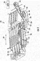
- FIG 3 is a perspective view illustrating an example crop separating portion of a harvester, shown as a harvester cleaning shoe 200, comprising an example harvester reciprocating drive balancing system 220.
- Harvester cleaning shoe 200 comprises housing 201, a fan 202, a housing 204, an upper sieve assembly 206, a lower sieve assembly 208, hangers 210, hangers 212 and a drive 232 comprising a motor 234, a drive crank 236, shaft 240 (shown in Figure 4 ), belt drive 244, driven pulley 246, belt 248 and gear reduction mechanism 250 (schematically shown in Figure 4 ).
- Sieve assemblies 206, 208 and drive 232 form an example harvester reciprocating drive balancing system 320, an example implementation of system 20 described above.
- Sieve assemblies 206, 208 serve as crop material separating members that are movably supported for reciprocal movement in the directions indicated by arrow 334. During such reciprocation, crop material deposited upon or above such sieve assemblies 206, 208 is separated into various components. Grain falls through the louvers 230 of sieve assemblies 206, 208 while straw or chaff is blown rearwardly by fan 202 for subsequent discharge.
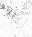
- gear reduction mechanism 450 comprises ring gear 470, input shaft 472, planetary gear carrier 474, planetary gears 476, sun gear 478 and output shaft 480.
- Ring gear 470 is provided as part of a much larger housing 482 fixed are secured to structural bodies of the harvester to resist rotation.
- Input shaft 472 comprises a shaft extending from driven pulley 46 so as to rotate with driven pulley 46.
- Input shaft 472 is fixed to planetary gear carrier 474 which rotatably supports each of planetary gears 476.
- Sun gear 478 is fixed to output shaft 480 and is in meshing engagement with each of planetary gears 476.
- Output shaft 480 extends from sun gear 478 and is operably coupled to input shaft 42 (shown in Figure 1 ). Rotation of driven pulley 246 rotates input shaft 472, carrier 474 and planetary gears 476 about the axis of shaft 472.
- Planetary gears 476 mesh with sun gear 478 to drive output shaft 480.
Landscapes
- Life Sciences & Earth Sciences (AREA)
- Environmental Sciences (AREA)
- Harvesting Machines For Root Crops (AREA)
- Retarders (AREA)
- Transmission Devices (AREA)
Abstract
Description
- Harvesters, such as combines, may use a variety of reciprocating crop material separating members to separate grain from remaining portions of the crop material. For example, many harvesters employ reciprocating chaffers or seives through which grain falls while the remaining material other than grain is blown rearwardly and discharged. Many harvesters employ straw walkers that are reciprocated to separate straw or stalks from grain or grain carrying portions of the crop material.
-
- Fig. 1
- is a schematic diagram of an example harvester reciprocating drive balancing system.
- Fig. 2
- is a flow diagram of an example method for separating constituents of crop material.
- Fig. 3
- is a top perspective view of an example harvester cleaning shoe comprising an example harvester reciprocating drive balancing system.
- Fig. 4
- is a sectional view of a portion of the example harvester reciprocating drive balancing system of the cleaning shoe of
Figure 3 . - Fig. 5
- is a perspective view of an example harvester reciprocating drive balancing system.
- Many harvesters comprise crop material separating members that are reciprocated to facilitate separation of grain from the remaining material other than grain. Many harvesters utilize a belt drive system to reciprocatively drive the crop material separating members. The reciprocation of the crop material separating members may result in speed and torque variations in the drive system. For example, at the end of an eccentric stroke of a crank arm, the system may experience accelerations. Such speed and torque variations may cause rapid degradation of the belt or belt of the belt drive system.
- Disclosed herein are example harvester reciprocating drive balancing systems and an example method that reduce such speed variations to potentially prolong the life of the belts of the belt drive system. The example harvester reciprocating drive balancing systems and the example method utilize a gear reduction mechanism in combination with a flywheel to store energy or provide inertia that dampens any speed variations that might otherwise occur during reciprocation of the harvester crop separating members. The gear reduction mechanism facilitates driving of a driven pulley at a much greater speed than at which the shaft that reciprocates the crop separating members is driven. The gear reduction mechanism provides increased inertia or energy storage without corresponding increases in the mass of the flywheel. As a result, gear reduction mechanism provides enhanced dampening of speed variations while at the same time facilitating a reduction in the size and weight of the flywheel.
- Disclosed herein is an example harvester reciprocating drive balancing system. The harvester reciprocating drive balancing system comprises a crop material separating member movably supported for reciprocal movement and a drive operably coupled to the crop material separating member to reciprocate the crop material separating member. The drive may include a drive crank operably coupled to the crop material separating member, a shaft operably coupled to the drive crank, a belt drive, a driven pulley, a belt wrapped about the belt drive and the driven pulley and a gear reduction mechanism operably coupled between the driven pulley and the shaft.
- Disclosed herein is an example harvester cleaning shoe. The harvester cleaning shoe comprises a sieve movably supported for reciprocal movement and a drive operably coupled to the sieve to reciprocate the sieve. The drive comprises a drive crank operably coupled to the crop material separating member, a shaft operably coupled to the drive crank, a belt drive, a driven pulley serving as a flywheel, a belt wrapped about the belt drive and the driven pulley and a planetary gear mechanism. The planetary gear mechanism comprises a ring gear coupled to the driven pulley to rotate with the driven pulley, a sun gear coupled to the shaft to rotate with the shaft and a planetary gear inner mashed between the ring gear and the sun gear.
- Disclosed herein is an example method for separating portions of crop material. The example method comprises rotatably driving a driven pulley, serving as a flywheel, at a first speed, transmitting torque from the driven pulley to a shaft across a gear reduction mechanism to rotate the shaft at a second speed less than the first speed and transmitting torque from the shaft to a harvester crop material separating member to reciprocate the harvester crop material separating member.
-
Figure 1 schematically illustrates an example harvester reciprocatingdrive balancing system 20.System 20 reduces such speed variations to potentially prolong the life of the belts of the belt drive system.System 20 utilizes a gear reduction mechanism in combination with a flywheel to store energy or provide inertia that dampens any speed variations that might otherwise occur during reciprocation of the harvester crop separating members. The gear reduction mechanism facilitates driving of a driven pulley at a much greater speed than at which the shaft that reciprocates the crop separating members is driven. The gear reduction mechanism provides increased inertia or energy storage without corresponding increases in the mass of the flywheel. As a result, gear reduction mechanism provides enhanced dampening of speed variations while at the same time facilitating a reduction in the size and weight of the flywheel.System 20 comprises cropmaterial separating member 30, and drive 32. - Crop
material separating member 30 comprises a member that is configured to separate different portions of crop material asmember 30 is reciprocated, move back and forth, by drive 32. For purposes of this disclosure, the phrase "configured to" denotes an actual state of configuration that fundamentally ties the stated function/use to the physical characteristics of the feature proceeding the phrase "configured to". - Separating
member 30 is movably supported for reciprocal movement in the direction indicated byarrows 34. For example, in one implementation, separatingmember 30 may be movably supported by hangers or other members that allow cropmaterial separating member 30 to be rocked back and forth. In another implementation, separatingmember 30 may be movie supported in tracks that guide reciprocating movement ofmember 30. In one implementation, cropmaterial separating member 30 comprises a cleaning member of a harvester cleaning shoe such as a sieve or chaffer, wherein grain falls through openings in the sieve or chaffer and straw are chaff is blown or otherwise directed away for discharge. In one implementation, cropmaterial separating member 30 comprises a cleaning member of a harvester straw walker, wherein the individual walkers reciprocated back and forth with the straw being carried rearwardly for discharge and with the grain (and possibly some chaff) falling through and between the individual walkers. - Drive 32 reciprocates
member 30 in the directions indicated byarrows 34.Drive 30 comprisesdrive crank 40,input shaft 42,belt drive 44, drivenpulley 46,belt 48 andgear reduction mechanism 50.Drive crank 40 converts the torque a rotational motion ofinput shaft 42 to translational reciprocating motion. In the example illustrated,drive crank 40 comprises a crank wheel ordisc 52 and acrank arm 54.Disc 52 is rotatably driven byinput shaft 42 directly or indirectly via intermediate gears or an intermediate transmission. Crankarm 54 is eccentrically pivotally connected todisc 52 at afirst pivot 56 and is pivotally connected or coupled to cropmaterial separating member 30 at asecond pivot 58. As a result, rotation ofdisc 52 results in linear translational reciprocating motion ofmember 30. - In other implementations,
input shaft 42 may be operably coupled to crop separatingmember 30 by other drive crank configurations or by other mechanisms that produce reciprocating motion. For purposes of this disclosure, the term "coupled" shall mean the joining of two members directly or indirectly to one another. Such joining may be stationary in nature or movable in nature. Such joining may be achieved with the two members or the two members and any additional intermediate members being integrally formed as a single unitary body with one another or with the two members or the two members and any additional intermediate member being attached to one another. Such joining may be permanent in nature or alternatively may be removable or releasable in nature. The term "operably coupled" shall mean that two members are directly or indirectly joined such that motion may be transmitted from one member to the other member directly or via intermediate members. -
Belt drive 44drives belt 48. Thedrive 44 comprises a drive pulley operably coupled to an engine or motor that supplies torque, through a transmission, to rotatebelt drive 44.Belt 48 comprises an endless belt wrapped aboutbelt drive 44 and drivenpulley 46. In the example illustrated,belt drive 44 drives drivenpulley 46 at a faster rate or greater number of revolutions per minute as the rate a revolutions per minute thatshaft 42 is driven to reciprocatemember 30. - Driven
pulley 46 serves as a flywheel forsystem 20. Drivenpulley 46 may have a mass which provides an inertia to store and release kinetic energy resulting from speed variations insystem 20. For example, at the end of an eccentric stroke ofcrank arm 54, the system may experience accelerations. In some implementations, drivenpulley 46 may comprise rings or discs of weight mounted to the remainder ofpulley 46 to increase the inertia ofpulley 46. In some implementations,pulley 46 may have a sufficient mass without rings or discs mounted thereto. -
Gear reduction mechanism 50 is operably coupled between drivenpulley 46 andinput shaft 42.Gear reduction mechanism 50, sometimes also referred to as a speed reduction mechanism, converts a first speed, first torque input from drivenpulley 46 to a second lower speed higher and second higher torque output toshaft 42.Gear reduction mechanism 50 facilitates a multiplication of energy storage bydrive 32, a multiplication of the rotational inertia provided bydrive 42, without a corresponding increase in the mass of the drivenpulley 46 serving as a flywheel. As a result, the fly wheel provided by drivenpulley 46 may be lighter in weight and maybe more compact. At the same time, the greater inertia provided bydrive 32, resulting fromgear reduction mechanism 50, facilitates greater energy storage bydrive 32. The greater energy storage reduces or eliminates speed variations otherwise experienced bybelt 48 during the reciprocating driving ofmember 30. The greater inertia ofdrive 32 may be better able to absorb excess energy asshaft 42 is accelerating and maybe a better able to release excess energy asshaft 42 asshaft 42 is decelerating. As a result, degradation ofbelt 48 may be reduced. - In one implementation,
gear reduction mechanism 50 may comprise a planetary gear box. In such an implementation, the planetary gear box may further reduce the size increase the compactness ofdrive 32 and ofsystem 20. In other implementations,gear reduction mechanism 50 may comprise other gear speed reducing transmissions. -
Figure 2 is a flow diagram of anexample method 100 for separating crop material in a harvester.Method 100 reciprocates a crop material separating member while storing and releasing excess energy resulting from such reciprocation to reduce speed variations experienced by the drive and its belt or belts, reducing wear and degradation the belt or belts. Althoughmethod 100 is described as being carried out withsystem 20, it should be appreciated thatmethod 100 may be carried out with any of the harvester reciprocating drive balancing systems described hereafter or with any simile configured reciprocating drive balancing system in a harvester or other apparatus. - As shown by
block 104,belt drive 44 rotatably drives a drivenpulley 46. Drivenpulley 46 serves as a flywheel. The drivenpulley 46 is driven at a first speed or number of revolutions per minute. - As indicated by
block 108, drive 32 further transmits torque from drivenpulley 46 toshaft 42 across agear reduction mechanism 50 to rotate theshaft 42 at a second speed less than the first speed. As indicated byblock 112, torque fromshaft 42 is transmitted to harvester cropmaterial separating member 30, by crank 42 reciprocate harvester cropmaterial separating member 30. -
Method 100 facilitates a multiplication of energy storage bydrive 32, a multiplication of the rotational inertia provided bydrive 42, without a corresponding increase in the mass of the drivenpulley 46 serving as a flywheel. As a result, the fly wheel provided by drivenpulley 46 may be lighter in weight and maybe more compact. At the same time, the greater inertia provided bydrive 32, resulting fromgear reduction mechanism 50, facilitates greater energy storage bydrive 32. The greater energy storage reduces or eliminates speed variations otherwise experienced bybelt 48 during the reciprocating driving ofmember 30. The greater inertia ofdrive 32 may be better able to absorb excess energy asshaft 42 is accelerating and may be better able to release excess energy asshaft 42 asshaft 42 is decelerating. As a result, degradation ofbelt 48 may be reduced. -
Figure 3 is a perspective view illustrating an example crop separating portion of a harvester, shown as aharvester cleaning shoe 200, comprising an example harvester reciprocating drive balancing system 220.Harvester cleaning shoe 200 compriseshousing 201, afan 202, a housing 204, anupper sieve assembly 206, alower sieve assembly 208,hangers 210,hangers 212 and adrive 232 comprising amotor 234, a drive crank 236, shaft 240 (shown inFigure 4 ),belt drive 244, drivenpulley 246,belt 248 and gear reduction mechanism 250 (schematically shown inFigure 4 ). - Housing 101 comprise a structure that supports
fan 202 and motor 214.Fan 202 extends laterally across substantially the entire width of the cleaning shoe.Fan 202 generates an airflow that travels rearward toward theupper sieve assembly 206 and thelower sieve assembly 208. This air is conveyed upward through theupper sieve assembly 206 and thelower sieve assembly 208, levitating mass other than grain such as straw and chaff and carries the straw and chaff rearward and out of the agricultural harvester. - The
upper sieve assembly 206 comprises a frame 218 that is generally rectangular and an upper sieve 220 that is supported in the frame 218. Thelower sieve assembly 208 comprises a frame 222 and a lower sieve 224 that is supported in the frame 222. Upper sieve 222 and lower sieve 224 each comprise a rectangular frame 226 and supports 228 supporting a fore-and-aft extending array of laterally extendinglouvers 230. Each oflouvers 230 is pivotally supported by frame 126 and supports 128 to pivot about their respective longitudinal and laterally extending axes. - Each
hanger 210 has an upper end and a lower end. The upper end is pivotally coupled to the chassis (not shown) of the agricultural harvester. The lower end is pivotally coupled to theupper sieve assembly 206. By this arrangement, theupper sieve assembly 206 is suspended to pivot in reciprocate generally fore and aft. Thehangers 210 are disposed in a generally rectangular arrangement, to support the left front, left rear, right front, and right rear of the upper sieve assembly 106. Thus, thehangers 210 are disposed at and support theupper sieve assembly 206 at the four corners of theupper sieve assembly 206 disposed at and support the upper sieve assembly 106 at the four corners of theupper sieve assembly 206. - Each
hanger 212 has an upper end and a lower end. The upper end is pivotally coupled to the chassis (not shown) of the agricultural harvester. The lower end is pivotally coupled to thelower sieve assembly 208. By this arrangement theupper sieve assembly 206 is suspended to pivot generally fore-and-aft. Thehangers 212 are disposed in a generally rectangular arrangement to support the left front, left rear, right front, and right rear of the lower sieve assembly. Thus, thehangers 212 are disposed at and support thelower sieve assembly 108 at the four corners of thelower sieve assembly 208. -
Sieve assemblies drive balancing system 320, an example implementation ofsystem 20 described above.Sieve assemblies arrow 334. During such reciprocation, crop material deposited upon or abovesuch sieve assemblies louvers 230 ofsieve assemblies fan 202 for subsequent discharge. - Motor 234 (schematically illustrated) drives the remainder of
drive 232.Motor 234 comprises a hydraulic motor driven by an engine of the harvester.Motor 234 may be operably coupled tobelt drive 244 by an appropriate transmission. In the example illustrated,motor 234 rotatably drivesbelt drive 244 at a speed or number of revolutions per minute greater than the rate at which shaft 240 (shown in 4) is driven. -
Crank 240,belt drive 244, drivenpulley 246,belt 248 andgear reduction mechanism 250 are similar to crank 40,input shaft 42,belt drive 44, drivenpulley 46,belt 48 andgear reduction mechanism 50 described above.Figure 4 is a sectional view illustrating one example implementation ofinput shaft 42 and drivenpulley 46 operably coupled to one another by gear reduction mechanism 250 (schematically shown). As shown byFigure 4 , in the example illustrated, drivenpulley 246 is nested aboutinput shaft 240. Drivenpulley 246 comprises apulley engaging portion 260 and aflywheel weight 262 fastened to pulley engaging portion 2602 increase the weight and inertia of drivenpulley 246. - Driven
pulley 246 is operably coupled toinput shaft 242 bygear reduction mechanism 250. In one implementation, thereduction mechanism 250 has a gear reduction ratio of at least two to one. In one implementation, the reduction mechanism has a reduction ratio of at least 3 to 1. In one implementation,gear reduction mechanism 250 comprises a planetary gear box, providing compactness for its nesting within drivenpulley 246 between drivenpulley 246 andinput shaft 42. - In one implementation, driven
pulley 246, further includingweight 262 has a mass of less than or equal to 12Kg. In one implementation, the total inertia provided by drivenpulley 246 andgear reduction mechanism 250 absorbs energy so as to balance or level speed and torque variations ofdrive 232. In one implementation, the reduction ratio ofgear reduction mechanism 250, the mass of drivenpulley 246 and the rate at which drivenpulley 246 is rotatably driven bydrive 244 is based upon empirically determined or observed speed and torque variations experienced byshaft 42 during the reciprocating ofcrank 240 and the one or more crop material separating members, such assieve assemblies gear reduction mechanism 250 facilitates and much lighter, and potentially more compact driven pulley/flywheel 246. In one implementation, increasing the speed at which drivenpulley 246 is driven bydrive 244 by X times (a multiplication of the rate at whichinput shaft 242 must be driven to reciprocate the crop material separating member or members) with a corresponding gear speed reduction ratio of S provided bygear reduction mechanism 250 may increase the overall inertia and energy absorption capability ofdrive 232 by X2. For example, in one implementation,gear reduction mechanism 250 may have a gear reduction of three. In such an implementation, the overall inertia of drivenpulley 246 is 32 or 9 times that of the inertia that would otherwise result from the mere mass of driven pulley/flywheel 246 alone. -
Figure 5 is a diagram illustrating an example harvester reciprocating drive balancing system 420. System 420 is similar tosystem 20 except that system 420 is specifically illustrated as comprising a specific example gear reduction mechanism 450 operably coupling cropmaterial separating member 30, via crank 40 (not shown), and drivenpulley 46 specifically illustrated as including or being mounted to aflywheel weight 262. Those components of system 420 which correspond to components ofsystem 20 described above are numbered similarly. - Gear reduction mechanism 450 comprises a planetary gear box comprising a ring gear, a son gear, a planetary gear carrier and planet gears.
Figure 5 illustrates one example planetary gear box. It should be appreciated that gear reduction mechanism 450 may comprise a planetary gear box having a variety of other planetary gear box configurations other than the illustrated example. - In the example illustrated, gear reduction mechanism 450 comprises
ring gear 470, input shaft 472,planetary gear carrier 474,planetary gears 476, sun gear 478 andoutput shaft 480.Ring gear 470 is provided as part of a much larger housing 482 fixed are secured to structural bodies of the harvester to resist rotation. Input shaft 472 comprises a shaft extending from drivenpulley 46 so as to rotate with drivenpulley 46. Input shaft 472 is fixed toplanetary gear carrier 474 which rotatably supports each ofplanetary gears 476. Sun gear 478 is fixed tooutput shaft 480 and is in meshing engagement with each ofplanetary gears 476.Output shaft 480 extends from sun gear 478 and is operably coupled to input shaft 42 (shown inFigure 1 ). Rotation of drivenpulley 246 rotates input shaft 472,carrier 474 andplanetary gears 476 about the axis of shaft 472.Planetary gears 476 mesh with sun gear 478 to driveoutput shaft 480. - In one implementation, gear reduction mechanism 450 provides a 3 to 1 speed or gear reduction ratio. As a result, the speed at which driven
pulley 46 and input shaft 472 are driven is reduced by a factor of 3 atoutput shaft 480. In other implementations, gear reduction mechanism 450 may provide other speeder gear reduction ratios. In other implementations, gear reduction mechanism 450 may have other configurations. For example, gear reduction mechanism 450, in some implementations, may be at least partially nested within drivenpulley 46. System 420 may be utilized in place ofsystem 320 inharvester cleaning shoe 200 described above, whereinsieve assemblies system 20 may be employed in other agricultural equipment, agricultural implements or non-agricultural systems that drive one or more members (not necessarily crop material separating members) in a reciprocating manner and which experience speed and/or torque variations as a result of such reciprocation. - Although the present disclosure has been described with reference to example implementations, workers skilled in the art will recognize that changes may be made in form and detail without departing from the spirit and scope of the claimed subject matter. For example, although different example implementations may have been described as including one or more features providing one or more benefits, it is contemplated that the described features may be interchanged with one another or alternatively be combined with one another in the described example implementations or in other alternative implementations. Because the technology of the present disclosure is relatively complex, not all changes in the technology are foreseeable. The present disclosure described with reference to the example implementations and set forth in the following claims is manifestly intended to be as broad as possible. For example, unless specifically otherwise noted, the claims reciting a single particular element also encompass a plurality of such particular elements.
Claims (10)
- A harvester reciprocating drive balancing system comprising:a crop material separating member movably supported for reciprocal movement;a drive operably coupled to the crop material separating member to reciprocate the crop material separating member, the drive comprising:a drive crank operably coupled to the crop material separating member;a shaft operably coupled to the drive crank;a belt drive;a driven pulley;a belt wrapped about the belt drive and the driven pulley; anda gear reduction mechanism operably coupled between the driven pulley and the shaft.
- The harvester reciprocating drive balancing system of claim 1, wherein the crop material separating member comprises a sieve.
- The harvester reciprocating drive balancing system of claim 1, wherein the gear reduction mechanism comprises a planetary gear system.
- The harvester reciprocating drive balancing system of claim 1, wherein the gear reduction mechanism comprises:a sun gear coupled to the shaft;a ring gear coupled to the driven pulley; anda planetary gear in meshing engagement with the ring gear and the sun gear.
- The harvester reciprocating drive balancing system of claim 1, wherein the driven pulley serves as a flywheel, the driven pulley having a mass of less than or equal to 15 Kg.
- The harvester reciprocating drive balancing system of claim 1, wherein the gear reduction system has a reduction ratio of at least 2 to 1.7. The harvester reciprocating drive balancing system of claim 1, wherein the gear reduction system has a reduction ratio of at least 3 to 1.
- The harvester reciprocating drive balancing system of claim 1, wherein the shaft undergoes a speed variation and a torque variation and wherein the mass of the flywheel, the velocity which the driven pulley is driven and the gear reduction ratio of the gear reduction mechanism are based upon the speed variation multiplied by the torque variation.
- A harvester cleaning shoe comprising:a sieve movably supported for reciprocal movement;a drive operably coupled to the sieve to reciprocate the sieve, the drive comprising:a drive crank operably coupled to the crop material separating member;a shaft operably coupled to the drive crank;a belt drive;a driven pulley serving as a flywheel;a belt wrapped about the belt drive and the driven pulley; anda planetary gear mechanism comprising:a ring gear coupled to the driven pulley to rotate with the driven pulley;a sun gear coupled to the shaft to rotate with the shaft; anda planetary gear inner mashed between the ring gear and the sun gear.
- The harvester cleaning shoe of claim 9, wherein the planetary gear has a reduction ratio of at least 3 to 1 and wherein the driven pulley, providing the flywheel, has a mass of less than or equal to 12 Kg.
- A method comprising:rotatably driving a driven pulley, serving as a flywheel, at a first speed;transmitting torque from the driven pulley to a shaft across a gear reduction mechanism to rotate the shaft at a second speed less than the first speed; andtransmitting torque from the shaft to a harvester crop material separating member to reciprocate the harvester crop material separating member.
Applications Claiming Priority (1)
| Application Number | Priority Date | Filing Date | Title |
|---|---|---|---|
| US15/294,553 US10426094B2 (en) | 2016-10-14 | 2016-10-14 | Harvester reciprocating drive balancing system |
Publications (2)
| Publication Number | Publication Date |
|---|---|
| EP3308628A1 true EP3308628A1 (en) | 2018-04-18 |
| EP3308628B1 EP3308628B1 (en) | 2020-09-30 |
Family
ID=60083863
Family Applications (1)
| Application Number | Title | Priority Date | Filing Date |
|---|---|---|---|
| EP17196342.4A Active EP3308628B1 (en) | 2016-10-14 | 2017-10-13 | Harvester reciprocating drive balancing system |
Country Status (4)
| Country | Link |
|---|---|
| US (1) | US10426094B2 (en) |
| EP (1) | EP3308628B1 (en) |
| CN (1) | CN107950205A (en) |
| BR (1) | BR102017019526B1 (en) |
Cited By (1)
| Publication number | Priority date | Publication date | Assignee | Title |
|---|---|---|---|---|
| EP3799714A4 (en) * | 2018-06-01 | 2021-09-15 | Izquierdo Puebla, Miguel Ángel | STORAGE OF ANTIVIBRATION SCREEN |
Families Citing this family (1)
| Publication number | Priority date | Publication date | Assignee | Title |
|---|---|---|---|---|
| CN118010249B (en) * | 2024-04-10 | 2024-06-28 | 摩多利智能传动(江苏)有限公司 | Dynamic balance testing device for planetary reducer |
Citations (3)
| Publication number | Priority date | Publication date | Assignee | Title |
|---|---|---|---|---|
| US6412260B1 (en) * | 2000-10-25 | 2002-07-02 | Case Corporation | Direct drive system with a flywheel for an agricultural combine |
| US20080004092A1 (en) * | 2006-06-30 | 2008-01-03 | Deere & Company, A Delaware Corporation | Remote sieve or chaffer adjustment |
| EP2936967A1 (en) * | 2014-04-22 | 2015-10-28 | CNH Industrial Belgium nv | Combine harvester with variable stroke cleaning shoe |
Family Cites Families (22)
| Publication number | Priority date | Publication date | Assignee | Title |
|---|---|---|---|---|
| US4198802A (en) | 1977-08-18 | 1980-04-22 | Deere & Company | Axial flow rotary separator for a combine |
| US4400930A (en) * | 1982-05-10 | 1983-08-30 | Allis-Chalmers Corporation | Harvester threshing rotor drive having variable speed belt drive and clutching means |
| JPH0544606Y2 (en) * | 1988-04-30 | 1993-11-12 | ||
| CN2287784Y (en) * | 1997-04-21 | 1998-08-19 | 常熟市机械附件厂 | Portable multifunctional thresher |
| CN2611681Y (en) * | 2003-04-19 | 2004-04-14 | 冯建国 | Double-quality pulley damper |
| CN2708624Y (en) * | 2004-04-09 | 2005-07-13 | 巴特尔 | Multifunction harvester |
| GB2415349A (en) * | 2004-06-22 | 2005-12-28 | Cnh Belgium Nv | Grain cleaning system for a combine harvester. |
| CN2857441Y (en) * | 2005-11-01 | 2007-01-17 | 张掖市天轮机械贸易有限责任公司 | High-straw crop harvester |
| US7805919B2 (en) | 2007-12-06 | 2010-10-05 | Cnh America Llc | Offset epicyclic sickle drive for a header of an agricultural plant cutting machine |
| DE102009026870A1 (en) | 2009-06-09 | 2010-12-16 | Deere & Company, Moline | Straw walker arrangement for combine utilized for harvesting grain fruit, has drive provided for increasing or decreasing rotating speed of crankshaft following one on other, where drive rotates crankshaft about axis |
| FR2997154B1 (en) * | 2012-10-18 | 2016-03-04 | France Reducteurs | VARIATOR OF BELT SPEED |
| BE1021121B1 (en) * | 2013-01-03 | 2016-02-15 | Cnh Industrial Belgium Nv | A HARVESTING MACHINE CONTAINING A STRAW HOLDER CONTROL SYSTEM |
| DE102013103450A1 (en) | 2013-04-08 | 2014-10-09 | Claas Selbstfahrende Erntemaschinen Gmbh | As a belt drive trained drive system of a self-propelled combine harvester |
| CN103250513B (en) * | 2013-05-02 | 2015-07-15 | 山东理工大学 | Self-propelled corn-harvesting straw-bundling combined machine |
| CN103317071B (en) * | 2013-05-23 | 2015-08-05 | 西安交通大学 | A kind of transmission system of alternating-current servo direct drive type hotdie forging press |
| CN103406252B (en) * | 2013-08-27 | 2016-03-02 | 安吉县迎客松花木场 | A kind of bark plane screening machine |
| CN109937683B (en) * | 2013-09-27 | 2020-11-03 | 株式会社久保田 | Combine harvester |
| CN203748288U (en) * | 2014-03-13 | 2014-08-06 | 刘大华 | Vibrating screen transmission device of peanut picker |
| US9487073B2 (en) * | 2014-04-17 | 2016-11-08 | Deere & Company | Power train for continuously variable power transmission |
| CN204031870U (en) * | 2014-08-27 | 2014-12-24 | 重庆市农业科学院 | Combine compound cleaning plant |
| CN104373505A (en) * | 2014-10-27 | 2015-02-25 | 韦莉 | Flywheel special for diesel |
| CN204860072U (en) * | 2015-08-20 | 2015-12-16 | 南通棉花机械有限公司 | Improve rice and wheat combining of structure and make a bundle compound workover rig |
-
2016
- 2016-10-14 US US15/294,553 patent/US10426094B2/en active Active
-
2017
- 2017-09-12 CN CN201710817348.3A patent/CN107950205A/en active Pending
- 2017-09-13 BR BR102017019526-0A patent/BR102017019526B1/en active IP Right Grant
- 2017-10-13 EP EP17196342.4A patent/EP3308628B1/en active Active
Patent Citations (3)
| Publication number | Priority date | Publication date | Assignee | Title |
|---|---|---|---|---|
| US6412260B1 (en) * | 2000-10-25 | 2002-07-02 | Case Corporation | Direct drive system with a flywheel for an agricultural combine |
| US20080004092A1 (en) * | 2006-06-30 | 2008-01-03 | Deere & Company, A Delaware Corporation | Remote sieve or chaffer adjustment |
| EP2936967A1 (en) * | 2014-04-22 | 2015-10-28 | CNH Industrial Belgium nv | Combine harvester with variable stroke cleaning shoe |
Cited By (1)
| Publication number | Priority date | Publication date | Assignee | Title |
|---|---|---|---|---|
| EP3799714A4 (en) * | 2018-06-01 | 2021-09-15 | Izquierdo Puebla, Miguel Ángel | STORAGE OF ANTIVIBRATION SCREEN |
Also Published As
| Publication number | Publication date |
|---|---|
| CN107950205A (en) | 2018-04-24 |
| US20180103590A1 (en) | 2018-04-19 |
| BR102017019526B1 (en) | 2022-04-26 |
| EP3308628B1 (en) | 2020-09-30 |
| BR102017019526A2 (en) | 2018-05-02 |
| US10426094B2 (en) | 2019-10-01 |
Similar Documents
| Publication | Publication Date | Title |
|---|---|---|
| US6412260B1 (en) | Direct drive system with a flywheel for an agricultural combine | |
| EP3072383B1 (en) | Grain-moving arrangement for an agricultural combine | |
| US11252872B2 (en) | Cleaning device for even material distribution via shaking and harvester equipped therewith | |
| WO2008005339A2 (en) | Remote sieve or chaffer adjustment | |
| EP2949199B1 (en) | Combine harvester cleaning system drive assembly | |
| US4915671A (en) | Vibratory seed crop harvesting method and apparatus | |
| EP2713694A1 (en) | Timing apparatus for separately driven sickle knives | |
| EP3308628B1 (en) | Harvester reciprocating drive balancing system | |
| WO2019010567A1 (en) | Center drive for sickle knife | |
| CN205292268U (en) | Working vehicle | |
| JP2013005784A (en) | Normal type combine harvester | |
| EP3158853A1 (en) | Drive arm for agricultural harvester cleaner | |
| EP2989884A1 (en) | Integrated jackshaft for grain elevators of agricultural combines | |
| KR102282513B1 (en) | Threshing device of combine | |
| KR20150133218A (en) | Combine | |
| US3494115A (en) | Vibrational grain separating apparatus for agricultural combines | |
| EP3363279B1 (en) | Harvester electrical energy generation | |
| JP3869320B2 (en) | Combine | |
| CN223274536U (en) | A threshing and separation system for harvesting machinery | |
| JP2017046621A (en) | Combine-harvester | |
| JP4054791B2 (en) | Combine | |
| JP6041724B2 (en) | Combine | |
| JPS6224425Y2 (en) | ||
| JP2015224612A (en) | Combine | |
| JP3252400B2 (en) | Threshing equipment |
Legal Events
| Date | Code | Title | Description |
|---|---|---|---|
| PUAI | Public reference made under article 153(3) epc to a published international application that has entered the european phase |
Free format text: ORIGINAL CODE: 0009012 |
|
| STAA | Information on the status of an ep patent application or granted ep patent |
Free format text: STATUS: THE APPLICATION HAS BEEN PUBLISHED |
|
| AK | Designated contracting states |
Kind code of ref document: A1 Designated state(s): AL AT BE BG CH CY CZ DE DK EE ES FI FR GB GR HR HU IE IS IT LI LT LU LV MC MK MT NL NO PL PT RO RS SE SI SK SM TR |
|
| AX | Request for extension of the european patent |
Extension state: BA ME |
|
| STAA | Information on the status of an ep patent application or granted ep patent |
Free format text: STATUS: REQUEST FOR EXAMINATION WAS MADE |
|
| 17P | Request for examination filed |
Effective date: 20181018 |
|
| RBV | Designated contracting states (corrected) |
Designated state(s): AL AT BE BG CH CY CZ DE DK EE ES FI FR GB GR HR HU IE IS IT LI LT LU LV MC MK MT NL NO PL PT RO RS SE SI SK SM TR |
|
| GRAP | Despatch of communication of intention to grant a patent |
Free format text: ORIGINAL CODE: EPIDOSNIGR1 |
|
| STAA | Information on the status of an ep patent application or granted ep patent |
Free format text: STATUS: GRANT OF PATENT IS INTENDED |
|
| INTG | Intention to grant announced |
Effective date: 20200507 |
|
| GRAS | Grant fee paid |
Free format text: ORIGINAL CODE: EPIDOSNIGR3 |
|
| GRAA | (expected) grant |
Free format text: ORIGINAL CODE: 0009210 |
|
| STAA | Information on the status of an ep patent application or granted ep patent |
Free format text: STATUS: THE PATENT HAS BEEN GRANTED |
|
| AK | Designated contracting states |
Kind code of ref document: B1 Designated state(s): AL AT BE BG CH CY CZ DE DK EE ES FI FR GB GR HR HU IE IS IT LI LT LU LV MC MK MT NL NO PL PT RO RS SE SI SK SM TR |
|
| REG | Reference to a national code |
Ref country code: CH Ref legal event code: EP Ref country code: GB Ref legal event code: FG4D |
|
| REG | Reference to a national code |
Ref country code: DE Ref legal event code: R096 Ref document number: 602017024504 Country of ref document: DE Ref country code: AT Ref legal event code: REF Ref document number: 1317801 Country of ref document: AT Kind code of ref document: T Effective date: 20201015 |
|
| REG | Reference to a national code |
Ref country code: IE Ref legal event code: FG4D |
|
| PG25 | Lapsed in a contracting state [announced via postgrant information from national office to epo] |
Ref country code: HR Free format text: LAPSE BECAUSE OF FAILURE TO SUBMIT A TRANSLATION OF THE DESCRIPTION OR TO PAY THE FEE WITHIN THE PRESCRIBED TIME-LIMIT Effective date: 20200930 Ref country code: BG Free format text: LAPSE BECAUSE OF FAILURE TO SUBMIT A TRANSLATION OF THE DESCRIPTION OR TO PAY THE FEE WITHIN THE PRESCRIBED TIME-LIMIT Effective date: 20201230 Ref country code: SE Free format text: LAPSE BECAUSE OF FAILURE TO SUBMIT A TRANSLATION OF THE DESCRIPTION OR TO PAY THE FEE WITHIN THE PRESCRIBED TIME-LIMIT Effective date: 20200930 Ref country code: FI Free format text: LAPSE BECAUSE OF FAILURE TO SUBMIT A TRANSLATION OF THE DESCRIPTION OR TO PAY THE FEE WITHIN THE PRESCRIBED TIME-LIMIT Effective date: 20200930 Ref country code: GR Free format text: LAPSE BECAUSE OF FAILURE TO SUBMIT A TRANSLATION OF THE DESCRIPTION OR TO PAY THE FEE WITHIN THE PRESCRIBED TIME-LIMIT Effective date: 20201231 Ref country code: NO Free format text: LAPSE BECAUSE OF FAILURE TO SUBMIT A TRANSLATION OF THE DESCRIPTION OR TO PAY THE FEE WITHIN THE PRESCRIBED TIME-LIMIT Effective date: 20201230 |
|
| REG | Reference to a national code |
Ref country code: AT Ref legal event code: MK05 Ref document number: 1317801 Country of ref document: AT Kind code of ref document: T Effective date: 20200930 |
|
| PG25 | Lapsed in a contracting state [announced via postgrant information from national office to epo] |
Ref country code: LV Free format text: LAPSE BECAUSE OF FAILURE TO SUBMIT A TRANSLATION OF THE DESCRIPTION OR TO PAY THE FEE WITHIN THE PRESCRIBED TIME-LIMIT Effective date: 20200930 Ref country code: RS Free format text: LAPSE BECAUSE OF FAILURE TO SUBMIT A TRANSLATION OF THE DESCRIPTION OR TO PAY THE FEE WITHIN THE PRESCRIBED TIME-LIMIT Effective date: 20200930 |
|
| REG | Reference to a national code |
Ref country code: NL Ref legal event code: MP Effective date: 20200930 |
|
| REG | Reference to a national code |
Ref country code: LT Ref legal event code: MG4D |
|
| PG25 | Lapsed in a contracting state [announced via postgrant information from national office to epo] |
Ref country code: SM Free format text: LAPSE BECAUSE OF FAILURE TO SUBMIT A TRANSLATION OF THE DESCRIPTION OR TO PAY THE FEE WITHIN THE PRESCRIBED TIME-LIMIT Effective date: 20200930 Ref country code: EE Free format text: LAPSE BECAUSE OF FAILURE TO SUBMIT A TRANSLATION OF THE DESCRIPTION OR TO PAY THE FEE WITHIN THE PRESCRIBED TIME-LIMIT Effective date: 20200930 Ref country code: RO Free format text: LAPSE BECAUSE OF FAILURE TO SUBMIT A TRANSLATION OF THE DESCRIPTION OR TO PAY THE FEE WITHIN THE PRESCRIBED TIME-LIMIT Effective date: 20200930 Ref country code: PT Free format text: LAPSE BECAUSE OF FAILURE TO SUBMIT A TRANSLATION OF THE DESCRIPTION OR TO PAY THE FEE WITHIN THE PRESCRIBED TIME-LIMIT Effective date: 20210201 Ref country code: CZ Free format text: LAPSE BECAUSE OF FAILURE TO SUBMIT A TRANSLATION OF THE DESCRIPTION OR TO PAY THE FEE WITHIN THE PRESCRIBED TIME-LIMIT Effective date: 20200930 Ref country code: LT Free format text: LAPSE BECAUSE OF FAILURE TO SUBMIT A TRANSLATION OF THE DESCRIPTION OR TO PAY THE FEE WITHIN THE PRESCRIBED TIME-LIMIT Effective date: 20200930 |
|
| PG25 | Lapsed in a contracting state [announced via postgrant information from national office to epo] |
Ref country code: IS Free format text: LAPSE BECAUSE OF FAILURE TO SUBMIT A TRANSLATION OF THE DESCRIPTION OR TO PAY THE FEE WITHIN THE PRESCRIBED TIME-LIMIT Effective date: 20210130 Ref country code: PL Free format text: LAPSE BECAUSE OF FAILURE TO SUBMIT A TRANSLATION OF THE DESCRIPTION OR TO PAY THE FEE WITHIN THE PRESCRIBED TIME-LIMIT Effective date: 20200930 Ref country code: ES Free format text: LAPSE BECAUSE OF FAILURE TO SUBMIT A TRANSLATION OF THE DESCRIPTION OR TO PAY THE FEE WITHIN THE PRESCRIBED TIME-LIMIT Effective date: 20200930 Ref country code: AT Free format text: LAPSE BECAUSE OF FAILURE TO SUBMIT A TRANSLATION OF THE DESCRIPTION OR TO PAY THE FEE WITHIN THE PRESCRIBED TIME-LIMIT Effective date: 20200930 Ref country code: AL Free format text: LAPSE BECAUSE OF FAILURE TO SUBMIT A TRANSLATION OF THE DESCRIPTION OR TO PAY THE FEE WITHIN THE PRESCRIBED TIME-LIMIT Effective date: 20200930 |
|
| REG | Reference to a national code |
Ref country code: CH Ref legal event code: PL |
|
| PG25 | Lapsed in a contracting state [announced via postgrant information from national office to epo] |
Ref country code: MC Free format text: LAPSE BECAUSE OF FAILURE TO SUBMIT A TRANSLATION OF THE DESCRIPTION OR TO PAY THE FEE WITHIN THE PRESCRIBED TIME-LIMIT Effective date: 20200930 Ref country code: SK Free format text: LAPSE BECAUSE OF FAILURE TO SUBMIT A TRANSLATION OF THE DESCRIPTION OR TO PAY THE FEE WITHIN THE PRESCRIBED TIME-LIMIT Effective date: 20200930 Ref country code: NL Free format text: LAPSE BECAUSE OF FAILURE TO SUBMIT A TRANSLATION OF THE DESCRIPTION OR TO PAY THE FEE WITHIN THE PRESCRIBED TIME-LIMIT Effective date: 20200930 Ref country code: LU Free format text: LAPSE BECAUSE OF NON-PAYMENT OF DUE FEES Effective date: 20201013 |
|
| REG | Reference to a national code |
Ref country code: DE Ref legal event code: R097 Ref document number: 602017024504 Country of ref document: DE |
|
| REG | Reference to a national code |
Ref country code: BE Ref legal event code: MM Effective date: 20201031 |
|
| PLBE | No opposition filed within time limit |
Free format text: ORIGINAL CODE: 0009261 |
|
| STAA | Information on the status of an ep patent application or granted ep patent |
Free format text: STATUS: NO OPPOSITION FILED WITHIN TIME LIMIT |
|
| PG25 | Lapsed in a contracting state [announced via postgrant information from national office to epo] |
Ref country code: DK Free format text: LAPSE BECAUSE OF FAILURE TO SUBMIT A TRANSLATION OF THE DESCRIPTION OR TO PAY THE FEE WITHIN THE PRESCRIBED TIME-LIMIT Effective date: 20200930 Ref country code: LI Free format text: LAPSE BECAUSE OF NON-PAYMENT OF DUE FEES Effective date: 20201031 Ref country code: CH Free format text: LAPSE BECAUSE OF NON-PAYMENT OF DUE FEES Effective date: 20201031 Ref country code: BE Free format text: LAPSE BECAUSE OF NON-PAYMENT OF DUE FEES Effective date: 20201031 |
|
| 26N | No opposition filed |
Effective date: 20210701 |
|
| PG25 | Lapsed in a contracting state [announced via postgrant information from national office to epo] |
Ref country code: IT Free format text: LAPSE BECAUSE OF FAILURE TO SUBMIT A TRANSLATION OF THE DESCRIPTION OR TO PAY THE FEE WITHIN THE PRESCRIBED TIME-LIMIT Effective date: 20200930 Ref country code: FR Free format text: LAPSE BECAUSE OF NON-PAYMENT OF DUE FEES Effective date: 20201130 Ref country code: IE Free format text: LAPSE BECAUSE OF NON-PAYMENT OF DUE FEES Effective date: 20201013 |
|
| PG25 | Lapsed in a contracting state [announced via postgrant information from national office to epo] |
Ref country code: SI Free format text: LAPSE BECAUSE OF FAILURE TO SUBMIT A TRANSLATION OF THE DESCRIPTION OR TO PAY THE FEE WITHIN THE PRESCRIBED TIME-LIMIT Effective date: 20200930 |
|
| PG25 | Lapsed in a contracting state [announced via postgrant information from national office to epo] |
Ref country code: IS Free format text: LAPSE BECAUSE OF FAILURE TO SUBMIT A TRANSLATION OF THE DESCRIPTION OR TO PAY THE FEE WITHIN THE PRESCRIBED TIME-LIMIT Effective date: 20210130 Ref country code: TR Free format text: LAPSE BECAUSE OF FAILURE TO SUBMIT A TRANSLATION OF THE DESCRIPTION OR TO PAY THE FEE WITHIN THE PRESCRIBED TIME-LIMIT Effective date: 20200930 Ref country code: MT Free format text: LAPSE BECAUSE OF FAILURE TO SUBMIT A TRANSLATION OF THE DESCRIPTION OR TO PAY THE FEE WITHIN THE PRESCRIBED TIME-LIMIT Effective date: 20200930 Ref country code: CY Free format text: LAPSE BECAUSE OF FAILURE TO SUBMIT A TRANSLATION OF THE DESCRIPTION OR TO PAY THE FEE WITHIN THE PRESCRIBED TIME-LIMIT Effective date: 20200930 |
|
| GBPC | Gb: european patent ceased through non-payment of renewal fee |
Effective date: 20211013 |
|
| PG25 | Lapsed in a contracting state [announced via postgrant information from national office to epo] |
Ref country code: MK Free format text: LAPSE BECAUSE OF FAILURE TO SUBMIT A TRANSLATION OF THE DESCRIPTION OR TO PAY THE FEE WITHIN THE PRESCRIBED TIME-LIMIT Effective date: 20200930 |
|
| PG25 | Lapsed in a contracting state [announced via postgrant information from national office to epo] |
Ref country code: GB Free format text: LAPSE BECAUSE OF NON-PAYMENT OF DUE FEES Effective date: 20211013 |
|
| PGFP | Annual fee paid to national office [announced via postgrant information from national office to epo] |
Ref country code: DE Payment date: 20250919 Year of fee payment: 9 |