EP3308382B1 - Ambient light suppression using color space information to derive pixel-wise attenuation factors - Google Patents
Ambient light suppression using color space information to derive pixel-wise attenuation factors Download PDFInfo
- Publication number
- EP3308382B1 EP3308382B1 EP16713702.5A EP16713702A EP3308382B1 EP 3308382 B1 EP3308382 B1 EP 3308382B1 EP 16713702 A EP16713702 A EP 16713702A EP 3308382 B1 EP3308382 B1 EP 3308382B1
- Authority
- EP
- European Patent Office
- Prior art keywords
- image
- mlc
- ambient light
- leaves
- pixels
- Prior art date
- Legal status (The legal status is an assumption and is not a legal conclusion. Google has not performed a legal analysis and makes no representation as to the accuracy of the status listed.)
- Active
Links
Images




Classifications
-
- A—HUMAN NECESSITIES
- A61—MEDICAL OR VETERINARY SCIENCE; HYGIENE
- A61B—DIAGNOSIS; SURGERY; IDENTIFICATION
- A61B6/00—Apparatus or devices for radiation diagnosis; Apparatus or devices for radiation diagnosis combined with radiation therapy equipment
- A61B6/50—Apparatus or devices for radiation diagnosis; Apparatus or devices for radiation diagnosis combined with radiation therapy equipment specially adapted for specific body parts; specially adapted for specific clinical applications
-
- A—HUMAN NECESSITIES
- A61—MEDICAL OR VETERINARY SCIENCE; HYGIENE
- A61N—ELECTROTHERAPY; MAGNETOTHERAPY; RADIATION THERAPY; ULTRASOUND THERAPY
- A61N5/00—Radiation therapy
- A61N5/10—X-ray therapy; Gamma-ray therapy; Particle-irradiation therapy
- A61N5/1042—X-ray therapy; Gamma-ray therapy; Particle-irradiation therapy with spatial modulation of the radiation beam within the treatment head
- A61N5/1045—X-ray therapy; Gamma-ray therapy; Particle-irradiation therapy with spatial modulation of the radiation beam within the treatment head using a multi-leaf collimator, e.g. for intensity modulated radiation therapy or IMRT
-
- G—PHYSICS
- G06—COMPUTING OR CALCULATING; COUNTING
- G06T—IMAGE DATA PROCESSING OR GENERATION, IN GENERAL
- G06T5/00—Image enhancement or restoration
- G06T5/20—Image enhancement or restoration using local operators
- G06T5/30—Erosion or dilatation, e.g. thinning
-
- G—PHYSICS
- G06—COMPUTING OR CALCULATING; COUNTING
- G06T—IMAGE DATA PROCESSING OR GENERATION, IN GENERAL
- G06T5/00—Image enhancement or restoration
- G06T5/70—Denoising; Smoothing
-
- G—PHYSICS
- G06—COMPUTING OR CALCULATING; COUNTING
- G06T—IMAGE DATA PROCESSING OR GENERATION, IN GENERAL
- G06T5/00—Image enhancement or restoration
- G06T5/90—Dynamic range modification of images or parts thereof
-
- G—PHYSICS
- G06—COMPUTING OR CALCULATING; COUNTING
- G06T—IMAGE DATA PROCESSING OR GENERATION, IN GENERAL
- G06T7/00—Image analysis
- G06T7/10—Segmentation; Edge detection
- G06T7/13—Edge detection
-
- G—PHYSICS
- G06—COMPUTING OR CALCULATING; COUNTING
- G06T—IMAGE DATA PROCESSING OR GENERATION, IN GENERAL
- G06T7/00—Image analysis
- G06T7/70—Determining position or orientation of objects or cameras
-
- G—PHYSICS
- G06—COMPUTING OR CALCULATING; COUNTING
- G06T—IMAGE DATA PROCESSING OR GENERATION, IN GENERAL
- G06T7/00—Image analysis
- G06T7/90—Determination of colour characteristics
-
- G—PHYSICS
- G21—NUCLEAR PHYSICS; NUCLEAR ENGINEERING
- G21K—HANDLING OF PARTICLES OR IONISING RADIATION NOT OTHERWISE PROVIDED FOR; IRRADIATION DEVICES; GAMMA RAY OR X-RAY MICROSCOPES
- G21K1/00—Arrangements for handling particles or ionising radiation, e.g. focusing or moderating
- G21K1/02—Arrangements for handling particles or ionising radiation, e.g. focusing or moderating using diaphragms, collimators
- G21K1/04—Arrangements for handling particles or ionising radiation, e.g. focusing or moderating using diaphragms, collimators using variable diaphragms, shutters, choppers
- G21K1/046—Arrangements for handling particles or ionising radiation, e.g. focusing or moderating using diaphragms, collimators using variable diaphragms, shutters, choppers varying the contour of the field, e.g. multileaf collimators
-
- H—ELECTRICITY
- H04—ELECTRIC COMMUNICATION TECHNIQUE
- H04N—PICTORIAL COMMUNICATION, e.g. TELEVISION
- H04N23/00—Cameras or camera modules comprising electronic image sensors; Control thereof
- H04N23/80—Camera processing pipelines; Components thereof
- H04N23/84—Camera processing pipelines; Components thereof for processing colour signals
- H04N23/88—Camera processing pipelines; Components thereof for processing colour signals for colour balance, e.g. white-balance circuits or colour temperature control
-
- H—ELECTRICITY
- H04—ELECTRIC COMMUNICATION TECHNIQUE
- H04N—PICTORIAL COMMUNICATION, e.g. TELEVISION
- H04N9/00—Details of colour television systems
- H04N9/64—Circuits for processing colour signals
- H04N9/646—Circuits for processing colour signals for image enhancement, e.g. vertical detail restoration, cross-colour elimination, contour correction, chrominance trapping filters
-
- A—HUMAN NECESSITIES
- A61—MEDICAL OR VETERINARY SCIENCE; HYGIENE
- A61B—DIAGNOSIS; SURGERY; IDENTIFICATION
- A61B6/00—Apparatus or devices for radiation diagnosis; Apparatus or devices for radiation diagnosis combined with radiation therapy equipment
- A61B6/02—Arrangements for diagnosis sequentially in different planes; Stereoscopic radiation diagnosis
- A61B6/022—Stereoscopic imaging
-
- A—HUMAN NECESSITIES
- A61—MEDICAL OR VETERINARY SCIENCE; HYGIENE
- A61B—DIAGNOSIS; SURGERY; IDENTIFICATION
- A61B6/00—Apparatus or devices for radiation diagnosis; Apparatus or devices for radiation diagnosis combined with radiation therapy equipment
- A61B6/02—Arrangements for diagnosis sequentially in different planes; Stereoscopic radiation diagnosis
- A61B6/03—Computed tomography [CT]
- A61B6/032—Transmission computed tomography [CT]
Definitions
- Embodiments of the present disclosure relate to an optical camera based tracking system for a multi-leaf collimator (MLC) used in radiation treatment systems and, in particular, to suppressing effects of ambient light entering the MLC housing on the camera based tracking system.
- MLC multi-leaf collimator
- collimators are frequently used in radiation treatment for shaping a beam of highly energized particles, referred to as a treatment beam.
- Some radiation treatment systems use a variable aperture collimator called a multi-leaf collimator (MLC).
- MLC multi-leaf collimator
- a multi-leaf collimator is a collimator that is made up of a collection of individual leaves that can move independently in and out of the path of the treatment beam.
- the MLC enables conformal shaping of the treatment beam. Accordingly, an image-based feedback can be used to ensure accurate placement of the individual leaves.
- Prior art document US 4 882 741 A discloses a collimating arrangement for use in radiotherapy apparatus, which a set of mutually contiguous members for substantially attenuating radiation.
- the positions of the members are adjustable so that edges thereof form an adjustable aperture for defining the cross-sectional shape of the beam.
- a lamp illuminates an area including the beam-defining edges.
- Each of the members is provided with a respective retroreflector for reflecting illumination from the lamp into the camera substantially independently of the position of the beam-defining edges.
- a detecting arrangement including a video camera, more responsive to the higher intensity of illumination reflected from the retroreflectors than from respectively adjacent regions in the illuminated area, is used to detect the positions of the retroreflectors which are respectively representative of the positions of the edges of the members.
- Prior art document US 4 672 212 A discloses a multi-leaf collimator for a radiation beam the particles of which is selected from the group consisting of high energy photons, electrons, protons and heavy ions which are emitted from a small effective radiation source.
- the collimator comprises low height, elongated, curved, in cross section wedge-shaped leaves arranged side by side in opposed pairs. The configuration is such that the parts of the surfaces intersecting the irradiation field will always be directed generally towards the radiation source.
- a protective casing surrounding a frame on which the collimator is mounted can be filled with helium gas to optimize the collimator for use with electron and photon beams in the energy range from 1 up to 50 MeV.
- the individual settings of the leaves are supervised by a TV-camera which also can be used to set the leaves in predetermined positions.
- the method according to the present invention is defined by claim 1.
- the radiation system according to the present invention is defined by claim 11. Further embodiments of the invention are defined by the dependent claims.
- a camera-based leaf positon feedback system having a camera located inside the collimator housing, is implemented.
- the camera-based leaf tracking system operates by detecting leaf features (e.g., notch, edge, protrusion, etc.) visible on images of leaf surface. Because the camera is located inside the collimator housing where lighting is minimal, an LED lighting system located inside the housing is used to illuminate the surface of the leaves with light. External light may enter the collimator housing and reflect off the sides of the leaves on the inside of the aperture. This creates undesirable illumination in the aperture, including near the leading edges of the leaves that shape the aperture. Such illumination can make visual tracking and verification of leaf position difficult.
- leaf features e.g., notch, edge, protrusion, etc.
- Embodiments of the present disclosure describe ambient light suppressing techniques that may include white balancing operations, determining color saturation, producing an ambient light attenuation map and applying the ambient light attenuation map to the original image.
- Various embodiments allow for an accurate visual verification of the location of the leaves by reducing undesired illumination throughout the aperture and, in particular, near the leading edges of the leaves that shape the aperture.
- these embodiments may be applied to other types of imaging systems that are subject to ambient light effects.
- the camera-based feedback system may be a primary feedback system.
- the camera-based feedback system may be a secondary feedback system.
- the method described herein may also be used with any characterized light source (knowing the primary color wavelength).
- the color may be selected based on the operating environment in order to maximize color separation between the internal system and ambient light.
- the color selection may be done at the time of installation of the LINAC 101 at a treatment facility or at the time of manufacturing. For example, if a lighting system is also installed in the treatment room, a desired internal color could be selected for the installation.
- a sensor could be held in the MLC aperture (e.g., illustrated by aperture 202) with MLC lighting system 107 turned off to measure the color of the ambient light in the MLC.
- any color deemed too close to the measured color e.g., using a metric such as the Delta-E metric used by the International Commission on Illumination (CIE) to compute the most different color, or an L2 distance in RGB/chromaticity space
- CIE International Commission on Illumination
- This may eliminate a need for a white balancing operation (e.g., operation 420 of Figure 4 ) discussed below that may be performed in accordance with one embodiment.
- the ambient lighting conditions of a radiation treatment room, in which the MLC housing is used may be analyzed to determine the most dissimilar MLC lighting color (wavelength) which may be performed in various ways.
- the optimal internal light may be YELLOW ([1,1,0]) which is a combination of RED and GREEN resulting in the largest separation along the three independent color axes.
- HSV Hue, Saturation and Value
- Figures 1A and 1C illustrate different views of embodiments of components of a radiation treatment system having a robot based linear accelerator (LINAC) 101 with a changeable collimator 100.
- the radiation treatment system 102 includes a radiation treatment robot having a LINAC 101 mounted on a robotic arm 103.
- Collimator housing 100 may contain any one of various types of collimators (e.g., an iris collimator, an MLC, etc.) of different apertures that may be detachably mounted to the LINAC 101.
- the different collimators may reside in collimator table 104, where the radiation treatment robotic may be moved to pick up and drop off collimators based on the collimator type.
- the particular aperture is matched to the specifics of a radiation treatment plan.
- collimator housing 100 represents a collimator housing that includes a MLC.
- the methods described herein may be used with other types of variable aperture collimators and other types of radiation treatment systems (e.g., gantry based LINAC treatment systems).
- FIG. 1B illustrates a cross sectional side view 1B-1B' taken from Figure 1A of MLC housing 100.
- MLC housing 100 includes an internal (e.g., LED) lighting system 107, including LED lights 108 and diffusers 110, that is used to illuminate the interior of the MLC housing 100.
- the camera feedback system utilizes a camera 105 to capture live images of the individual leaf locations of the MLC banks (e.g., 106). It should be noted that camera 105 may include optics and an image sensor including other electronics associated with camera 105, located farther away from the beam path so as not to be effected by the radiation beam. Camera 105, and its associated electronics, and lighting system 107, may be part of the camera feedback system that is connected to the digital processing system 670. Digital processing system 670 is further described in relation to Figure 6 with respect to the implementation of the operations described in relation to Figure 4
- the radiation treatment system comprises the MLC disposed within the housing, the lighting system disposed within the housing and the imaging system having optics situated inside the housing.
- ambient light 109 enters the MLC housing 100 (represented by vector 119) through an aperture between two banks of leaves in the MLC housing 100.
- Figure 1B is a cross section side view of the MLC housing 100, only one of the banks of leaves is shown in the figure.
- the aperture is an opening between two banks of leaves that allows for the passage of radiation beams generated by the LINAC 101, as illustrated in Figures 2A-B .
- the ambient light 109 passes through the aperture formed by the MLC bank 106 and opposing bank 111, it reflects off the sides of the leaves on the inside of the aperture.
- Figure 2A illustrates a view from inside the MLC housing 100 as captured by the camera 105 of Figure 1 .
- the ambient light 109 enters the MLC housing 100 it reflects off the sides of the leaves of the MLC bank 106 on the inside of the aperture in the general region indicated by the dashed ellipse 202.
- the aperture may be the region formed by the central, leading edges of the leaves of the MLC banks 106 and 111.
- Figure 2B illustrates the undesired illumination 204. near the central, leading edges of the leaves of the MLC banks 106 and 111 caused by the ambient light 109.
- the undesired illumination 204 (whose shape is more illustrative of the aperture generally identified by reference numeral 202) can affect the ability of the camera feedback system to determine and verify the location of the individual leaves of the MLC banks 106 and 111 by creating visual patterns in the aperture that may falsely be identified as a trackable leaf feature (which, in one embodiment, may be a notch in the leaf but can also be other types of features such as an edge of a leaf) and by changing the appearance of the image near the actual trackable leaf feature.
- a trackable leaf feature which, in one embodiment, may be a notch in the leaf but can also be other types of features such as an edge of a leaf
- FIG 3 illustrates an image 300 of the inside surface of the MLC housing 100 from the perspective of the optical imaging system.
- Ambient light enters through the aperture 202 (whose reference numeral arrow pointing to the central area formed by the leading edges of the leaves of MLC bank 106), illuminating the metallic surfaces located inside the MLC housing 100 of Figure 1 .
- ambient light is shown as more greatly illuminating the lower area 302 of aperture 202.
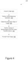
- Figure 4 illustrates a flow diagram of a method 400 for suppressing effects of ambient light in an imaging system.
- Method 400 is described in relation to the suppression of ambient light entering MLC housing and affecting an optical camera based imaging system used to track MLC leaf positions.
- method 400 may also be used to suppress ambient light in other imaging systems that are subject to ambient light effects and, in particular, where ambient light is constrained in a region and the region is not intended to be illuminated or it is desirable to force the affected region to be dark.
- the method 400 may be performed by processing logic that comprises hardware (e.g., circuitry, dedicated logic, programmable logic, microcode, etc.), software (e.g., instructions run on a processing device to perform hardware simulation), or a combination thereof.
- processing logic captures an image of the MLC banks surface and aperture using the feedback system camera 105.
- optional white balancing operations may be performed if the camera and the internal lighting system do not already result in mechanical surfaces (e.g., leaves of MLC banks) within the collimator housing appearing grayscale (approximately colorless) when viewed from the camera with only internal light present.
- mechanical surfaces e.g., leaves of MLC banks
- grayscale approximately colorless
- a white balancing operation may be performed to compensate for such radiation induced changes in the camera system.
- a white balance operation may be performed, for example, if the internal lighting system of the MLC housing 100 is not approximately gray or mapped to gray by some operations.
- a region of interest ROI is selected, where the ROI is a mechanical surface of the MLC banks 106, 111 illuminated only by the internal lighting system.
- an ROI may be designated as the visible surface area of the leaves of MLC bank 106 with a closed aperture (e.g., when the leaves are in a location that prevents ambient light from entering the housing).
- an average RGB pixel value, v is calculated over all pixels located within the ROI, resulting in an average red pixel value, average green pixel value and an average blue pixel value.
- pixel A has RGB values of [96; 256; 256] and pixel B has RGB values of [32; 0; 128].
- the resultant average RGB pixel value is [64; 128; 192]. It should be noted that the pixels' value provided herein are only examples solely intended to aid in explanation of the methods described herein. Although an embodiment using RGB space is discussed herein, in other embodiments, other ways may be used to achieve the effect of minimizing average color saturation for an ROI that may not involve the RGB color space.
- a scalar intensity factor, s is calculated.
- the scalar intensity factor includes the average of the three values of the average RGB pixel value.
- the scalar intensity factor would be the average of these three values, resulting in a scalar intensity factor of 128.
- the values of the average RGB pixel value, v, and the scalar intensity factor, s may be used to calculate a white balance parameter vector, g.
- the white balance parameter vector is calculated as the inverse of the average RGB pixel value multiplied by the scalar intensity factor, as shown in the equation below.
- g s / v
- the white balance parameter vector may be applied by pixel-wise multiplication to correct the pixels in subsequent images (as such, the white balance operation 420 may consist only of applying the computed white balance, which may be computed less frequently to account for changes in the system hardware). It should be noted that although there is a single correction g, it is applied to all pixels in subsequent images.
- the corrected pixel has a saturation of zero (i.e., the same values for red, green and blue) and the same average intensity over the three color channels.
- This gives the appearance of the leaves and other metal surfaces inside the MLC housing 100 as nearly being grayscale (i.e., having a small computed color saturation value).
- a different algorithm may be used for the white balancing operation.
- Examples may be, but are not limited to, normalizing pixel intensities by their L2-norm, perceptual intensity or a metric other than the average RGB value.
- the metric may be computed in a different color space, for example, if the camera 105 has a native color space other than RGB.
- a camera hardware-based white balance operation may be used when settings are obtained based on an ROI with no ambient light.
- processing logic determines a saturation map for the image captured at block 410.
- a saturation map is a representation of the color saturation of each pixel in an image.
- the white balancing step may be omitted and the saturation map may be a representation of a distance in color space between each pixel's color and a reference color (i.e. a well-characterized color pertaining to the appearance of the MLC leaf surfaces illuminated by the internal lighting system as captured by the camera in the absence of ambient light).
- a series of morphological and non-linear transformations are applied to the saturation map (or a map of distance in color space to a reference color), S, to produce an attenuation map, A, to suppress ambient light.
- the saturation is modulated by pixel brightness using equation 2, shown below, where V is an intensity (brightness) map.
- S S * 1 + V
- a sharp non-linear attenuation curve is created using equation 3, shown below.
- the desired sharp non-linear attenuation curve may initially have a high slope value with the slope value decreasing rapidly when a specified saturation value is reached.
- the cubic coefficients (a, b, c, d) may be determined empirically or computed for a certain type of ambient light (e.g., by fitting a curve to a desired response, where the x axis is saturation and the y axis is the inverse of desired attenuation) to obtain the desired attenuation curve or response for a certain type of ambient light. In this way, the sensitivity of the attenuation can be tuned to ambient light with a certain distribution of saturation value.
- any type of suitable transfer function may be used, such as an exponential or higher order polynomial or combination of transcendental functions.
- a morphological operation i.e., grayscale opening or erosion of the attenuation map, A
- the use of the morphological operation may be helpful if the source image has a large amount of noise or when the noise of color channels is independent.
- a final image is provided with ambient light being suppressed.
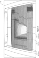
- Figure 5 illustrates the final image 500 created at block 450 for the image 300 shown in Figure 3 where the darker regions signify higher attenuation values relative to the lighter regions that signify lower attenuation values.
- the ambient light attenuation map highly attenuates pixels with high saturation values caused by ambient light, while minimally attenuating pixels that represent leaf locations (that were appropriately white balanced via block 420 or by other technique).
- the resulting image 500 shows the suppression of ambient light (along with a geometric correction), entering the MLC housing 100 through the aperture 202, for example as more prominently seen in lower area 502 as compared to lower area 302 of Figure 3 .
- the camera-based feedback system can more reliably verify and track the location of the individual leaves of the MLC bank 106.
- Figure 6 illustrates one embodiment of systems that may be used in performing radiation treatment. These systems may be used to perform, for example, the methods described above.
- a system 600 may include a diagnostic imaging system 605, a treatment planning system 610, a treatment delivery system 615 and a motion detecting system (not shown).
- the diagnostic imaging system 605 and the motion detecting system are combined into a single unit.
- Diagnostic imaging system 605 may be any system capable of producing medical diagnostic images of a patient that may be used for subsequent medical diagnosis, treatment planning, treatment simulation and/or treatment delivery.
- diagnostic imaging system 605 may be a computed tomography (CT) system, a magnetic resonance imaging (MRI) system, a positron emission tomography (PET) system, or the like.
- CT computed tomography
- MRI magnetic resonance imaging
- PET positron emission tomography
- diagnostic imaging system 605 may be discussed below at times in relation to an x-ray imaging modality. In other embodiments, other imaging modalities such as those discussed above may also be used.
- diagnostic imaging system 605 includes an imaging source 620 to generate an imaging beam (e.g., x-rays) and an imaging detector 630 to detect and receive the beam generated by imaging source 620, or a secondary beam or emission stimulated by the beam from the imaging source (e.g., in an MRI or PET scan).
- an imaging source 620 to generate an imaging beam (e.g., x-rays)
- an imaging detector 630 to detect and receive the beam generated by imaging source 620, or a secondary beam or emission stimulated by the beam from the imaging source (e.g., in an MRI or PET scan).
- imaging source 620 and imaging detector 630 may be coupled to a digital processing system 625 to control the imaging operation and process image data.
- diagnostic imaging system 605 may receive imaging commands from treatment delivery system 615.
- Diagnostic imaging system 605 includes a bus or other means 680 for transferring data and commands among digital processing system 625, imaging source 620 and imaging detector 630.
- Digital processing system 625 may include one or more general-purpose processors (e.g., a microprocessor), special purpose processor such as a digital signal processor (DSP) or other type of device such as a controller or field programmable gate array (FPGA).
- DSP digital signal processor
- FPGA field programmable gate array
- Digital processing system 625 may also include other components (not shown) such as memory, storage devices, network adapters and the like.
- Digital processing system 625 may be configured to generate digital diagnostic images in a standard format, such as the Digital Imaging and Communications in Medicine (DICOM) format, for example. In other embodiments, digital processing system 625 may generate other standard or non-standard digital image formats.
- DICOM Digital Imaging and Communications in Medicine
- Digital processing system 625 may transmit diagnostic image files (e.g., the aforementioned DICOM formatted files) to treatment delivery system 615 over a data link 683, which may be, for example, a direct link, a local area network (LAN) link or a wide area network (WAN) link such as the Internet.
- a data link 683 may be, for example, a direct link, a local area network (LAN) link or a wide area network (WAN) link such as the Internet.
- LAN local area network
- WAN wide area network
- the information transferred between systems may either be pulled or pushed across the communication medium connecting the systems, such as in a remote diagnosis or treatment planning configuration.
- a user may utilize embodiments of the present disclosure to diagnose or treat a patient despite the existence of a physical separation between the system user and the patient.
- treatment delivery system 615 includes a therapeutic and/or surgical radiation source 660 to administer a prescribed radiation dose to a target volume in conformance with a treatment plan.
- Treatment delivery system 615 may also include imaging system 665 to perform computed tomography (CT) such as cone beam CT, and images generated by imaging system 665 may be two-dimensional (2D) or three-dimensional (3D).
- CT computed tomography
- Treatment delivery system 615 may also include a digital processing system 670 to control radiation source 660, receive and process data from diagnostic imaging system 605 and/or treatment planning system 610, and control a patient support device such as a treatment couch 675.
- Digital processing system 670 may be connected to or a part of the camera feedback system described above and operate on the images captured by camera 105 of Figure 1 .
- Digital processing system 670 may be configured to register 2D radiographic images received from diagnostic imaging system 605, from two or more stereoscopic projections, with digitally reconstructed radiographs (DRRs) generated by digital processing system 625 in diagnostic imaging system 605 and/or DRRs generated by processing device 640 in treatment planning system 610.
- DRRs digitally reconstructed radiographs
- Digital processing system 670 may include a processing device that represents one or more general-purpose processors (e.g., a microprocessor), special purpose processor such as a digital signal processor (DSP) or other type of device such as a controller or field programmable gate array (FPGA).
- the processing device of digital processing system 670 may be configured to execute instructions to perform treatment delivery operations, for example, the method 400 described above in regards to Figure 4 .
- digital processing system 670 includes system memory that may include a random access memory (RAM), or other dynamic storage devices, coupled to a processing device, for storing information and instructions to be executed by the processing device.
- the system memory also may be used for storing temporary variables or other intermediate information during execution of instructions by the processing device.
- the system memory may also include a read only memory (ROM) and/or other static storage device for storing static information and instructions for the processing device.
- ROM read only memory
- Digital processing system 670 may also include a storage device, representing one or more storage devices (e.g., a magnetic disk drive or optical disk drive) for storing information and instructions.
- the storage device may be used for storing instructions for performing the treatment delivery steps discussed herein.
- Digital processing system 670 may be coupled to radiation source 660 and treatment couch 675 by a bus 692 or other type of control and communication interface.
- Digital processing system 670 may implement methods to manage timing of diagnostic x-ray imaging in order to maintain alignment of a target with a radiation treatment beam delivered by the radiation source 660.
- the treatment delivery system 615 includes an input device 678 and a display 677 connected with digital processing system 670 via bus 692.
- the display 677 can show trend data that identifies a rate of target movement (e.g., a rate of movement of a target volume that is under treatment).
- the display can also show a current radiation exposure of a patient and a projected radiation exposure for the patient.
- the input device 678 can enable a clinician to adjust parameters of a treatment delivery plan during treatment.
- Treatment planning system 610 includes a processing device 640 to generate and modify treatment plans and/or simulation plans.
- Processing device 640 may represent one or more general-purpose processors (e.g., a microprocessor), special purpose processor such as a digital signal processor (DSP) or other type of device such as a controller or field programmable gate array (FPGA).
- DSP digital signal processor
- FPGA field programmable gate array
- Processing device 640 may be configured to execute instructions for performing simulation generating operations and/or treatment planning operations discussed herein.
- Treatment planning system 610 may also include system memory 635 that may include a random access memory (RAM), or other dynamic storage devices, coupled to processing device 640 by bus 686, for storing information and instructions to be executed by processing device 640.
- System memory 635 also may be used for storing temporary variables or other intermediate information during execution of instructions by processing device 640.
- System memory 635 may also include a read only memory (ROM) and/or other static storage device coupled to bus 686 for storing static information and instructions for processing device 640.
- ROM read only memory
- Treatment planning system 610 may also include storage device 645, representing one or more storage devices (e.g., a magnetic disk drive or optical disk drive) coupled to bus 686 for storing information and instructions.
- Storage device 645 may be used for storing instructions for performing the treatment planning steps discussed herein.
- Processing device 640 may also be coupled to a display device 650, such as a cathode ray tube (CRT) or liquid crystal display (LCD), for displaying information (e.g., a 2D or 3D representation of the VOI) to the user.
- a display device 650 such as a cathode ray tube (CRT) or liquid crystal display (LCD)
- An input device 655 such as a keyboard, may be coupled to processing device 640 for communicating information and/or command selections to processing device 640.
- One or more other user input devices e.g., a mouse, a trackball or cursor direction keys
- Treatment planning system 610 may share its database (e.g., data stored in storage 645) with a treatment delivery system, such as treatment delivery system 615, so that it may not be necessary to export from the treatment planning system prior to treatment delivery.
- Treatment planning system 610 may be linked to treatment delivery system 615 via a data link 690, which in one embodiment may be a direct link, a LAN link or a WAN link.
- any of diagnostic imaging system 605, treatment planning system 610 and/or treatment delivery system 615 may be in decentralized locations such that the systems may be physically remote from each other.
- any of diagnostic imaging system 605, treatment planning system 610, and/or treatment delivery system 615 may be integrated with each other in one or more systems.
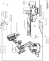
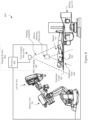
- FIGS 7 and 8 illustrate configurations of image-guided radiation treatment systems 700 and 800, in accordance with embodiments of the present disclosure.
- the radiation treatment systems 700 and 800 include a linear accelerator (LINAC) 701 that acts as a radiation treatment source, and an MLC housing 100.
- LINAC linear accelerator
- the LINAC 701 and MLC housing 100 are mounted on the end of a robotic arm 702 having multiple (e.g., 5 or more) degrees of freedom in order to position the LINAC 701 and MLC housing 100 to irradiate a pathological anatomy (e.g., target 720) with beams delivered from many angles, in many planes, in an operating volume around a patient.
- a pathological anatomy e.g., target 720
- Treatment may involve beam paths with a single isocenter, multiple isocenters, or with a non-isocentric approach.
- IGRT image guided radiation treatment
- the LINAC 701 and MLC housing 100 may be mounted on a gantry based system to provide isocentric beam paths.
- the IGRT system is the Vero SBRT System (referred to as TM200 in Japan), a joint product of Mitsubishi Heavy Industries Ltd., of Tokyo Japan and BrainLAB AG of Germany, that utilizes a rigid O-ring based gantry.
- the LINAC 701 and MLC housing 100 may be positioned at multiple different nodes (predefined positions at which the robot stops and radiation may be delivered) during treatment by moving the robotic arm 735.
- the LINAC 701 can deliver one or more radiation treatment beams to a target.
- the nodes may be arranged in an approximately spherical distribution about a patient.
- the particular number of nodes and the number of treatment beams applied at each node may vary as a function of the location and type of pathological anatomy to be treated. For example, the number of nodes may vary from 50 to 300, or more preferably 15 to 100 nodes and the number of beams may vary from 700 to 3200, or more preferably 50 to 300.
- radiation treatment system 700 includes an imaging system 665 having a processor 730 connected with x-ray sources 703A and 703B and fixed x-ray detectors 704A and 704B.
- the x-ray sources 703A, 703B and/or x-ray detectors 704A, 704B may be mobile, in which case they may be repositioned to maintain alignment with the target 720, or alternatively to image the target from different orientations or to acquire many x-ray images and reconstruct a three-dimensional (3D) cone-beam CT.
- the x-ray sources are not point sources, but rather x-ray source arrays, as would be appreciated by the skilled artisan.
- LINAC 701 serves as an imaging source (whether gantry or robot mounted), where the LINAC power level is reduced to acceptable levels for imaging.
- Imaging system 665 may perform computed tomography (CT) such as cone beam CT, and images generated by imaging system 665 may be two-dimensional (2D) or three-dimensional (3D).
- CT computed tomography
- the two x-ray sources 703A and 703B may be mounted in fixed positions on the ceiling of an operating room and may be aligned to project x-ray imaging beams from two different angular positions (e.g., separated by 90 degrees) to intersect at a machine isocenter (referred to herein as a treatment center, which provides a reference point for positioning the patient on a treatment couch 706 during treatment) and to illuminate imaging planes of respective detectors 704A and 704B after passing through the patient.
- a machine isocenter referred to herein as a treatment center, which provides a reference point for positioning the patient on a treatment couch 706 during treatment
- imaging system 665 provides stereoscopic imaging of the target 720 and the surrounding volume of interest (VOI).
- imaging system 665 may include more or less than two x-ray sources and more or less than two detectors, and any of the detectors may be movable rather than fixed.
- the positions of the x-ray sources and the detectors may be interchanged.
- Detectors 704A and 704B may be fabricated from a scintillating material that converts the x-rays to visible light (e.g., amorphous silicon), and an array of CMOS (complementary metal oxide silicon) or CCD (charge-coupled device) imaging cells that convert the light to a digital image that can be compared with a reference image during an image registration process that transforms a coordinate system of the digital image to a coordinate system of the reference image, as is well known to the skilled artisan.
- CMOS complementary metal oxide silicon
- CCD charge-coupled device
- the reference image may be, for example, a digitally reconstructed radiograph (DRR), which is a virtual x-ray image that is generated from a 3D CT image based on simulating the x-ray image formation process by casting rays through the CT image.
- DRR digitally reconstructed radiograph
- an imaging system 810 includes a motion detection device 812 to determine target motion, the motion detecting device 814 having a detection field 840.
- the motion detecting device 814 may detect external patient motion (such as chest movement during respiration) that occurs within an 850.
- the motion detecting device 814 can be any sensor or other device capable of identifying target movement.
- the motion detecting device 814 may be, for example an optical sensor such as a camera, a pressure sensor, an electromagnetic sensor, or some other sensor that can provide motion detection without delivering ionizing radiation to a user (e.g., a sensor other than an x-ray imaging system).
- the motion detecting device 814 acquires measurement data indicative of target motion in real-time.
- the measurement data may be acquired at a frequency that is higher (potentially substantially higher) than can be achieved or than is desirable with x-ray imaging (due to ionizing radiation delivered to the patient with each x-ray image).
- the motion detecting device 814 does not provide a high absolute position accuracy. Instead, the motion detecting device 814 may provide sufficient relative position accuracy to detect patient movement and/or target movement.
- the motion detecting device 814 is an optical system, such as a camera.
- the optical system may track the position of light-emitting diodes (LEDs) situated on patient 725.
- the optical system may directly track a surface region of patient 725, as distinguished from tracking LEDs on the patient.
- There may be a correlation between movement of the target and movement of the LEDs and/or surface region of the patient 725. Based on the correlation, when motion of the LEDs and/or surface region is detected, it can be determined that the target 720 has also moved sufficiently to require another diagnostic x-ray image to precisely determine the location of the target.
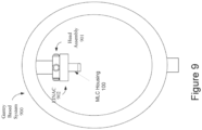
- FIG 9 illustrates one embodiment of a gantry based (isocentric) intensity modulated radiotherapy (IMRT) system 900.
- a radiation source e.g., a LINAC
- MLC multi-leaf collimator
- the gantry based system 900 may be a c-arm based system.
- aspects of the present disclosure may be embodied, at least in part, in software. That is, the techniques may be carried out in a computer system or other data processing system in response to its processor, such as digital processing system 670, for example, executing sequences of instructions contained in a memory.
- hardware circuitry may be used in combination with software instructions to implement the present disclosure.
- the techniques are not limited to any specific combination of hardware circuitry and software or to any particular source for the instructions executed by the data processing system.
- various functions and operations may be described as being performed by or caused by software code to simplify description. However, those skilled in the art will recognize what is meant by such expressions is that the functions result from execution of the code by a processor or controller, such as digital processing system 670.
- a machine-readable medium can be used to store software and data which when executed by a general purpose or special purpose data processing system causes the system to perform various methods of the present disclosure.
- This executable software and data may be stored in various places including, for example, system memory and storage or any other device that is capable of storing software programs and/or data.
- a machine-readable medium includes any mechanism that provides (i.e., stores) information in a form accessible by a machine (e.g., a computer, network device, personal digital assistant, manufacturing tool, any device with a set of one or more processors, etc.).
- a machine-readable medium includes recordable/non-recordable media such as read only memory (ROM), random access memory (RAM), magnetic disk storage media, optical storage media, flash memory devices, etc.
- processing may refer to the actions and processes of a computer system, or similar electronic computing device, that manipulates and transforms data represented as physical (e.g., electronic) quantities within the computer system's registers and memories into other data similarly represented as physical within the computer system memories or registers or other such information storage or display devices.
- Embodiments of the methods described herein may be implemented using computer software. If written in a programming language conforming to a recognized standard, sequences of instructions designed to implement the methods can be compiled for execution on a variety of hardware platforms and for interface to a variety of operating systems.
- embodiments of the present disclosure are not described with reference to any particular programming language. It will be appreciated that a variety of programming languages may be used to implement embodiments of the present disclosure.
- treatment may refer generally to the effectuation of an operation controlled by the treatment planning system, such as the application of a beam (e.g., radiation, acoustic, etc.) and "target” may refer to a non-anatomical object or area.
- a beam e.g., radiation, acoustic, etc.
- target may refer to a non-anatomical object or area.
Landscapes
- Engineering & Computer Science (AREA)
- Physics & Mathematics (AREA)
- General Physics & Mathematics (AREA)
- Theoretical Computer Science (AREA)
- Health & Medical Sciences (AREA)
- Computer Vision & Pattern Recognition (AREA)
- Life Sciences & Earth Sciences (AREA)
- Biomedical Technology (AREA)
- General Health & Medical Sciences (AREA)
- Public Health (AREA)
- Nuclear Medicine, Radiotherapy & Molecular Imaging (AREA)
- Radiology & Medical Imaging (AREA)
- Pathology (AREA)
- Animal Behavior & Ethology (AREA)
- Veterinary Medicine (AREA)
- High Energy & Nuclear Physics (AREA)
- Signal Processing (AREA)
- Medical Informatics (AREA)
- Multimedia (AREA)
- Biophysics (AREA)
- Dentistry (AREA)
- Oral & Maxillofacial Surgery (AREA)
- General Engineering & Computer Science (AREA)
- Spectroscopy & Molecular Physics (AREA)
- Optics & Photonics (AREA)
- Heart & Thoracic Surgery (AREA)
- Molecular Biology (AREA)
- Surgery (AREA)
- Image Processing (AREA)
- Radiation-Therapy Devices (AREA)
Description
- This application claims priority to
U.S. Provisional Patent App. No. 62/175,149 filed 06/12/2015 . - Embodiments of the present disclosure relate to an optical camera based tracking system for a multi-leaf collimator (MLC) used in radiation treatment systems and, in particular, to suppressing effects of ambient light entering the MLC housing on the camera based tracking system.
- Collimators are frequently used in radiation treatment for shaping a beam of highly energized particles, referred to as a treatment beam. Some radiation treatment systems use a variable aperture collimator called a multi-leaf collimator (MLC). A multi-leaf collimator is a collimator that is made up of a collection of individual leaves that can move independently in and out of the path of the treatment beam. For conformal radiation treatments, the MLC enables conformal shaping of the treatment beam. Accordingly, an image-based feedback can be used to ensure accurate placement of the individual leaves.
- Prior art document
US 4 882 741 A discloses a collimating arrangement for use in radiotherapy apparatus, which a set of mutually contiguous members for substantially attenuating radiation. The positions of the members are adjustable so that edges thereof form an adjustable aperture for defining the cross-sectional shape of the beam. A lamp illuminates an area including the beam-defining edges. Each of the members is provided with a respective retroreflector for reflecting illumination from the lamp into the camera substantially independently of the position of the beam-defining edges. A detecting arrangement, including a video camera, more responsive to the higher intensity of illumination reflected from the retroreflectors than from respectively adjacent regions in the illuminated area, is used to detect the positions of the retroreflectors which are respectively representative of the positions of the edges of the members. - Prior art document
US 4 672 212 A discloses a multi-leaf collimator for a radiation beam the particles of which is selected from the group consisting of high energy photons, electrons, protons and heavy ions which are emitted from a small effective radiation source. The collimator comprises low height, elongated, curved, in cross section wedge-shaped leaves arranged side by side in opposed pairs. The configuration is such that the parts of the surfaces intersecting the irradiation field will always be directed generally towards the radiation source. A protective casing surrounding a frame on which the collimator is mounted can be filled with helium gas to optimize the collimator for use with electron and photon beams in the energy range from 1 up to 50 MeV. The individual settings of the leaves are supervised by a TV-camera which also can be used to set the leaves in predetermined positions. - The present disclosure is illustrated by way of example, and not by way of limitation, in the figures of the accompanying drawings.
-
Figure 1A illustrates one embodiment of a components of a radiation treatment system having a robot based LINAC with a changeable variable aperture collimator, in accordance with embodiments of the present disclosure, -
Figure 1B illustrates a MLC housing utilizing a camera feedback system to verify leaf location, in accordance with embodiments of the present disclosure. -
Figure 1C illustrates another embodiment of components of a radiation treatment system having a robot based LINAC with a changeable variable aperture collimator, in accordance with embodiments of the present disclosure. -
Figures 2A-B illustrates views from inside the MLC housing, where ambient light is entering through the aperture of the MLC, in accordance with embodiments of the present disclosure. -
Figure 3 illustrates a feedback camera image of an MLC aperture, in accordance with embodiments of the present disclosure. -
Figure 4 illustrates a flow diagram of a method for suppressing ambient light in an imaging system, in accordance with embodiments of the present disclosure. -
Figure 5 illustrates the final image created for the feedback camera image shown inFigure 3 , in accordance with embodiments of the present disclosure. -
Figure 6 illustrates one embodiment of systems that may be used in performing radiation treatment, in accordance with embodiments of the present disclosure. -
Figure 7 illustrates an image-guided radiation treatment system, in accordance with embodiments of the present disclosure. -
Figure 8 illustrates a gantry based image-guided radiation treatment system, in accordance with embodiments of the present disclosure. -
Figure 9 illustrates a gantry based intensity modulated radiotherapy (IMRT) system in accordance with embodiments of the present disclosure. - The method according to the present invention is defined by claim 1. The radiation system according to the present invention is defined by claim 11. Further embodiments of the invention are defined by the dependent claims.
- Described herein is a method for suppressing effects of ambient light on a camera based tracking system. In one embodiment, to enable visual tracking and verification of MLC leaf positions in linear accelerator of a radiation treatment system, a camera-based leaf positon feedback system having a camera located inside the collimator housing, is implemented. The camera-based leaf tracking system operates by detecting leaf features (e.g., notch, edge, protrusion, etc.) visible on images of leaf surface. Because the camera is located inside the collimator housing where lighting is minimal, an LED lighting system located inside the housing is used to illuminate the surface of the leaves with light. External light may enter the collimator housing and reflect off the sides of the leaves on the inside of the aperture. This creates undesirable illumination in the aperture, including near the leading edges of the leaves that shape the aperture. Such illumination can make visual tracking and verification of leaf position difficult.
- Embodiments of the present disclosure describe ambient light suppressing techniques that may include white balancing operations, determining color saturation, producing an ambient light attenuation map and applying the ambient light attenuation map to the original image. Various embodiments allow for an accurate visual verification of the location of the leaves by reducing undesired illumination throughout the aperture and, in particular, near the leading edges of the leaves that shape the aperture. In addition, these embodiments may be applied to other types of imaging systems that are subject to ambient light effects. In one embodiment, the camera-based feedback system may be a primary feedback system. In another embodiment, the camera-based feedback system may be a secondary feedback system.
- It should be noted that while certain embodiments may be described herein in relation to white light, the method described herein may also be used with any characterized light source (knowing the primary color wavelength). The color may be selected based on the operating environment in order to maximize color separation between the internal system and ambient light. The color selection may be done at the time of installation of the LINAC 101 at a treatment facility or at the time of manufacturing. For example, if a lighting system is also installed in the treatment room, a desired internal color could be selected for the installation. Alternatively, at the time of installation of LINAC 101, a sensor could be held in the MLC aperture (e.g., illustrated by aperture 202) with
MLC lighting system 107 turned off to measure the color of the ambient light in the MLC. In this embodiment, which is not part of the claimed invention, any color deemed too close to the measured color (e.g., using a metric such as the Delta-E metric used by the International Commission on Illumination (CIE) to compute the most different color, or an L2 distance in RGB/chromaticity space) would be considered ambient. This may eliminate a need for a white balancing operation (e.g.,operation 420 ofFigure 4 ) discussed below that may be performed in accordance with one embodiment. In one particular embodiment, to maximize system performance, the ambient lighting conditions of a radiation treatment room, in which the MLC housing is used, may be analyzed to determine the most dissimilar MLC lighting color (wavelength) which may be performed in various ways. In one embodiment, if the ambient light is BLUE ([0,0,1]) in RGB space, for example, the optimal internal light may be YELLOW ([1,1,0]) which is a combination of RED and GREEN resulting in the largest separation along the three independent color axes. Another way to quantify the separation is in Hue, Saturation and Value (HSV) space where the first channel is hue/chrome.Figures 1A and1C illustrate different views of embodiments of components of a radiation treatment system having a robot based linear accelerator (LINAC) 101 with achangeable collimator 100. In one embodiment, theradiation treatment system 102 includes a radiation treatment robot having a LINAC 101 mounted on arobotic arm 103.Collimator housing 100 may contain any one of various types of collimators (e.g., an iris collimator, an MLC, etc.) of different apertures that may be detachably mounted to the LINAC 101. The different collimators may reside in collimator table 104, where the radiation treatment robotic may be moved to pick up and drop off collimators based on the collimator type. The particular aperture is matched to the specifics of a radiation treatment plan. In the embodiments described below,collimator housing 100 represents a collimator housing that includes a MLC. In alternative embodiments, the methods described herein may be used with other types of variable aperture collimators and other types of radiation treatment systems (e.g., gantry based LINAC treatment systems). -
Figure 1B illustrates a crosssectional side view 1B-1B' taken fromFigure 1A ofMLC housing 100.MLC housing 100 includes an internal (e.g., LED)lighting system 107, includingLED lights 108 and diffusers 110, that is used to illuminate the interior of theMLC housing 100. The camera feedback system utilizes acamera 105 to capture live images of the individual leaf locations of the MLC banks (e.g., 106). It should be noted thatcamera 105 may include optics and an image sensor including other electronics associated withcamera 105, located farther away from the beam path so as not to be effected by the radiation beam.Camera 105, and its associated electronics, andlighting system 107, may be part of the camera feedback system that is connected to thedigital processing system 670.Digital processing system 670 is further described in relation toFigure 6 with respect to the implementation of the operations described in relation toFigure 4 - According to the claimed invention, the radiation treatment system comprises the MLC disposed within the housing, the lighting system disposed within the housing and the imaging system having optics situated inside the housing.
- During operation of the
LINAC 101,ambient light 109 enters the MLC housing 100 (represented by vector 119) through an aperture between two banks of leaves in theMLC housing 100. It should be noted that sinceFigure 1B is a cross section side view of theMLC housing 100, only one of the banks of leaves is shown in the figure. The aperture is an opening between two banks of leaves that allows for the passage of radiation beams generated by theLINAC 101, as illustrated inFigures 2A-B . As the ambient light 109 passes through the aperture formed by theMLC bank 106 and opposingbank 111, it reflects off the sides of the leaves on the inside of the aperture. -
Figure 2A illustrates a view from inside theMLC housing 100 as captured by thecamera 105 ofFigure 1 . As theambient light 109 enters theMLC housing 100 it reflects off the sides of the leaves of theMLC bank 106 on the inside of the aperture in the general region indicated by the dashedellipse 202. It should be noted that the aperture may be the region formed by the central, leading edges of the leaves of theMLC banks Figure 2B illustrates theundesired illumination 204. near the central, leading edges of the leaves of theMLC banks ambient light 109. The undesired illumination 204 (whose shape is more illustrative of the aperture generally identified by reference numeral 202) can affect the ability of the camera feedback system to determine and verify the location of the individual leaves of theMLC banks -
Figure 3 illustrates animage 300 of the inside surface of theMLC housing 100 from the perspective of the optical imaging system. Ambient light enters through the aperture 202 (whose reference numeral arrow pointing to the central area formed by the leading edges of the leaves of MLC bank 106), illuminating the metallic surfaces located inside theMLC housing 100 ofFigure 1 . Here, ambient light is shown as more greatly illuminating thelower area 302 ofaperture 202. -
Figure 4 illustrates a flow diagram of amethod 400 for suppressing effects of ambient light in an imaging system.Method 400 is described in relation to the suppression of ambient light entering MLC housing and affecting an optical camera based imaging system used to track MLC leaf positions. However, it should be understood thatmethod 400 may also be used to suppress ambient light in other imaging systems that are subject to ambient light effects and, in particular, where ambient light is constrained in a region and the region is not intended to be illuminated or it is desirable to force the affected region to be dark. Themethod 400 may be performed by processing logic that comprises hardware (e.g., circuitry, dedicated logic, programmable logic, microcode, etc.), software (e.g., instructions run on a processing device to perform hardware simulation), or a combination thereof. - At
block 410, processing logic captures an image of the MLC banks surface and aperture using thefeedback system camera 105. Atblock 420, in one embodiment, optional white balancing operations may be performed if the camera and the internal lighting system do not already result in mechanical surfaces (e.g., leaves of MLC banks) within the collimator housing appearing grayscale (approximately colorless) when viewed from the camera with only internal light present. As the lens ofcamera 105 discolors and becomes more opaque and the performance of the image sensor ofcamera 105 changes due to the radiation environment in which the camera operates, a change in color can occur. A white balancing operation may be performed to compensate for such radiation induced changes in the camera system. - In one embodiment, a white balance operation may be performed, for example, if the internal lighting system of the
MLC housing 100 is not approximately gray or mapped to gray by some operations. To perform white balancing, a region of interest (ROI) is selected, where the ROI is a mechanical surface of theMLC banks MLC bank 106 with a closed aperture (e.g., when the leaves are in a location that prevents ambient light from entering the housing). Following the selection of the ROI, an average RGB pixel value, v, is calculated over all pixels located within the ROI, resulting in an average red pixel value, average green pixel value and an average blue pixel value. For example, in an ROI of two pixels, pixel A has RGB values of [96; 256; 256] and pixel B has RGB values of [32; 0; 128]. The resultant average RGB pixel value is [64; 128; 192]. It should be noted that the pixels' value provided herein are only examples solely intended to aid in explanation of the methods described herein. Although an embodiment using RGB space is discussed herein, in other embodiments, other ways may be used to achieve the effect of minimizing average color saturation for an ROI that may not involve the RGB color space. - Using the average RGB pixel value, a scalar intensity factor, s, is calculated. In one embodiment, the scalar intensity factor includes the average of the three values of the average RGB pixel value. Using the previous example with an average RGB pixel value of [64; 128; 192], the scalar intensity factor would be the average of these three values, resulting in a scalar intensity factor of 128. The values of the average RGB pixel value, v, and the scalar intensity factor, s, may be used to calculate a white balance parameter vector, g. The white balance parameter vector is calculated as the inverse of the average RGB pixel value multiplied by the scalar intensity factor, as shown in the equation below.

white balance operation 420 may consist only of applying the computed white balance, which may be computed less frequently to account for changes in the system hardware). It should be noted that although there is a single correction g, it is applied to all pixels in subsequent images. For example, given a pixel of RGB values [64; 128; 192], the corrected pixel RGB values would be [64*2.0; 128*1.0; 192*0.667] = [128; 128; 128]. The result is that the corrected pixel has a saturation of zero (i.e., the same values for red, green and blue) and the same average intensity over the three color channels. This gives the appearance of the leaves and other metal surfaces inside theMLC housing 100 as nearly being grayscale (i.e., having a small computed color saturation value). In some embodiments, a different algorithm may be used for the white balancing operation. Examples may be, but are not limited to, normalizing pixel intensities by their L2-norm, perceptual intensity or a metric other than the average RGB value. In one alternative embodiment, the metric may be computed in a different color space, for example, if thecamera 105 has a native color space other than RGB. In another embodiment, a camera hardware-based white balance operation may be used when settings are obtained based on an ROI with no ambient light. - At
block 430 ofmethod 400, processing logic determines a saturation map for the image captured atblock 410. In one embodiment, a saturation map is a representation of the color saturation of each pixel in an image. In another embodiment, the white balancing step may be omitted and the saturation map may be a representation of a distance in color space between each pixel's color and a reference color (i.e. a well-characterized color pertaining to the appearance of the MLC leaf surfaces illuminated by the internal lighting system as captured by the camera in the absence of ambient light). - At
block 440 of method 400 a series of morphological and non-linear transformations are applied to the saturation map (or a map of distance in color space to a reference color), S, to produce an attenuation map, A, to suppress ambient light. In one embodiment, the saturation is modulated by pixel brightness using equation 2, shown below, where V is an intensity (brightness) map.

- The cubic coefficients (a, b, c, d) may be determined empirically or computed for a certain type of ambient light (e.g., by fitting a curve to a desired response, where the x axis is saturation and the y axis is the inverse of desired attenuation) to obtain the desired attenuation curve or response for a certain type of ambient light. In this way, the sensitivity of the attenuation can be tuned to ambient light with a certain distribution of saturation value. In another embodiment, any type of suitable transfer function may be used, such as an exponential or higher order polynomial or combination of transcendental functions. A morphological operation (i.e., grayscale opening or erosion of the attenuation map, A) is performed to reduce noise and high frequency artifacts in the corrected image. The use of the morphological operation may be helpful if the source image has a large amount of noise or when the noise of color channels is independent. The ambient light attenuation map is then applied to the original image via pixel-wise multiplication (V = V * A). At
block 450, a final image is provided with ambient light being suppressed. - It should be noted that the above described operations are just one method of suppressing effects of ambient light and that, in alternative embodiments, certain ones of the operations of
Figure 4 may be optional or take a simpler form, for example, by use of a linear transformation instead of a non-linear transformation inblock 440. -
Figure 5 illustrates thefinal image 500 created atblock 450 for theimage 300 shown inFigure 3 where the darker regions signify higher attenuation values relative to the lighter regions that signify lower attenuation values. The ambient light attenuation map determined atblock 440 ofFigure 4 is applied to the entireoriginal image 300 through pixel-wise multiplication (V = V *A). The ambient light attenuation map highly attenuates pixels with high saturation values caused by ambient light, while minimally attenuating pixels that represent leaf locations (that were appropriately white balanced viablock 420 or by other technique). The resultingimage 500 shows the suppression of ambient light (along with a geometric correction), entering theMLC housing 100 through theaperture 202, for example as more prominently seen inlower area 502 as compared tolower area 302 ofFigure 3 . With the ambient light suppressed, the camera-based feedback system can more reliably verify and track the location of the individual leaves of theMLC bank 106. -
Figure 6 illustrates one embodiment of systems that may be used in performing radiation treatment. These systems may be used to perform, for example, the methods described above. As described below and illustrated inFigure 6 , asystem 600 may include adiagnostic imaging system 605, atreatment planning system 610, atreatment delivery system 615 and a motion detecting system (not shown). In one embodiment, thediagnostic imaging system 605 and the motion detecting system are combined into a single unit. -
Diagnostic imaging system 605 may be any system capable of producing medical diagnostic images of a patient that may be used for subsequent medical diagnosis, treatment planning, treatment simulation and/or treatment delivery. For example,diagnostic imaging system 605 may be a computed tomography (CT) system, a magnetic resonance imaging (MRI) system, a positron emission tomography (PET) system, or the like. For ease of discussion,diagnostic imaging system 605 may be discussed below at times in relation to an x-ray imaging modality. In other embodiments, other imaging modalities such as those discussed above may also be used. - In one embodiment,
diagnostic imaging system 605 includes animaging source 620 to generate an imaging beam (e.g., x-rays) and animaging detector 630 to detect and receive the beam generated byimaging source 620, or a secondary beam or emission stimulated by the beam from the imaging source (e.g., in an MRI or PET scan). - In one embodiment,
imaging source 620 andimaging detector 630 may be coupled to adigital processing system 625 to control the imaging operation and process image data. In one embodiment,diagnostic imaging system 605 may receive imaging commands fromtreatment delivery system 615. -
Diagnostic imaging system 605 includes a bus orother means 680 for transferring data and commands amongdigital processing system 625,imaging source 620 andimaging detector 630.Digital processing system 625 may include one or more general-purpose processors (e.g., a microprocessor), special purpose processor such as a digital signal processor (DSP) or other type of device such as a controller or field programmable gate array (FPGA).Digital processing system 625 may also include other components (not shown) such as memory, storage devices, network adapters and the like.Digital processing system 625 may be configured to generate digital diagnostic images in a standard format, such as the Digital Imaging and Communications in Medicine (DICOM) format, for example. In other embodiments,digital processing system 625 may generate other standard or non-standard digital image formats.Digital processing system 625 may transmit diagnostic image files (e.g., the aforementioned DICOM formatted files) totreatment delivery system 615 over adata link 683, which may be, for example, a direct link, a local area network (LAN) link or a wide area network (WAN) link such as the Internet. In addition, the information transferred between systems may either be pulled or pushed across the communication medium connecting the systems, such as in a remote diagnosis or treatment planning configuration. In remote diagnosis or treatment planning, a user may utilize embodiments of the present disclosure to diagnose or treat a patient despite the existence of a physical separation between the system user and the patient. - In one embodiment,
treatment delivery system 615 includes a therapeutic and/orsurgical radiation source 660 to administer a prescribed radiation dose to a target volume in conformance with a treatment plan.Treatment delivery system 615 may also includeimaging system 665 to perform computed tomography (CT) such as cone beam CT, and images generated byimaging system 665 may be two-dimensional (2D) or three-dimensional (3D). -
Treatment delivery system 615 may also include adigital processing system 670 to controlradiation source 660, receive and process data fromdiagnostic imaging system 605 and/ortreatment planning system 610, and control a patient support device such as atreatment couch 675.Digital processing system 670 may be connected to or a part of the camera feedback system described above and operate on the images captured bycamera 105 ofFigure 1 .Digital processing system 670 may be configured to register 2D radiographic images received fromdiagnostic imaging system 605, from two or more stereoscopic projections, with digitally reconstructed radiographs (DRRs) generated bydigital processing system 625 indiagnostic imaging system 605 and/or DRRs generated by processingdevice 640 intreatment planning system 610.Digital processing system 670 may include a processing device that represents one or more general-purpose processors (e.g., a microprocessor), special purpose processor such as a digital signal processor (DSP) or other type of device such as a controller or field programmable gate array (FPGA). The processing device ofdigital processing system 670 may be configured to execute instructions to perform treatment delivery operations, for example, themethod 400 described above in regards toFigure 4 . - In one embodiment,
digital processing system 670 includes system memory that may include a random access memory (RAM), or other dynamic storage devices, coupled to a processing device, for storing information and instructions to be executed by the processing device. The system memory also may be used for storing temporary variables or other intermediate information during execution of instructions by the processing device. The system memory may also include a read only memory (ROM) and/or other static storage device for storing static information and instructions for the processing device. -
Digital processing system 670 may also include a storage device, representing one or more storage devices (e.g., a magnetic disk drive or optical disk drive) for storing information and instructions. The storage device may be used for storing instructions for performing the treatment delivery steps discussed herein.Digital processing system 670 may be coupled toradiation source 660 andtreatment couch 675 by abus 692 or other type of control and communication interface. -
Digital processing system 670 may implement methods to manage timing of diagnostic x-ray imaging in order to maintain alignment of a target with a radiation treatment beam delivered by theradiation source 660. - In one embodiment, the
treatment delivery system 615 includes aninput device 678 and adisplay 677 connected withdigital processing system 670 viabus 692. Thedisplay 677 can show trend data that identifies a rate of target movement (e.g., a rate of movement of a target volume that is under treatment). The display can also show a current radiation exposure of a patient and a projected radiation exposure for the patient. Theinput device 678 can enable a clinician to adjust parameters of a treatment delivery plan during treatment. -
Treatment planning system 610 includes aprocessing device 640 to generate and modify treatment plans and/or simulation plans.Processing device 640 may represent one or more general-purpose processors (e.g., a microprocessor), special purpose processor such as a digital signal processor (DSP) or other type of device such as a controller or field programmable gate array (FPGA).Processing device 640 may be configured to execute instructions for performing simulation generating operations and/or treatment planning operations discussed herein. -
Treatment planning system 610 may also includesystem memory 635 that may include a random access memory (RAM), or other dynamic storage devices, coupled toprocessing device 640 bybus 686, for storing information and instructions to be executed by processingdevice 640.System memory 635 also may be used for storing temporary variables or other intermediate information during execution of instructions by processingdevice 640.System memory 635 may also include a read only memory (ROM) and/or other static storage device coupled tobus 686 for storing static information and instructions forprocessing device 640. -
Treatment planning system 610 may also includestorage device 645, representing one or more storage devices (e.g., a magnetic disk drive or optical disk drive) coupled tobus 686 for storing information and instructions.Storage device 645 may be used for storing instructions for performing the treatment planning steps discussed herein. -
Processing device 640 may also be coupled to adisplay device 650, such as a cathode ray tube (CRT) or liquid crystal display (LCD), for displaying information (e.g., a 2D or 3D representation of the VOI) to the user. Aninput device 655, such as a keyboard, may be coupled toprocessing device 640 for communicating information and/or command selections toprocessing device 640. One or more other user input devices (e.g., a mouse, a trackball or cursor direction keys) may also be used to communicate directional information, to select commands forprocessing device 640 and to control cursor movements ondisplay 650. -
Treatment planning system 610 may share its database (e.g., data stored in storage 645) with a treatment delivery system, such astreatment delivery system 615, so that it may not be necessary to export from the treatment planning system prior to treatment delivery.Treatment planning system 610 may be linked totreatment delivery system 615 via adata link 690, which in one embodiment may be a direct link, a LAN link or a WAN link. - It should be noted that when
data links diagnostic imaging system 605,treatment planning system 610 and/ortreatment delivery system 615 may be in decentralized locations such that the systems may be physically remote from each other. Alternatively, any ofdiagnostic imaging system 605,treatment planning system 610, and/ortreatment delivery system 615 may be integrated with each other in one or more systems. -
Figures 7 and8 illustrate configurations of image-guidedradiation treatment systems radiation treatment systems MLC housing 100. In one embodiment, the LINAC 701 andMLC housing 100 are mounted on the end of arobotic arm 702 having multiple (e.g., 5 or more) degrees of freedom in order to position the LINAC 701 andMLC housing 100 to irradiate a pathological anatomy (e.g., target 720) with beams delivered from many angles, in many planes, in an operating volume around a patient. Treatment may involve beam paths with a single isocenter, multiple isocenters, or with a non-isocentric approach. Alternatively, other types of image guided radiation treatment (IGRT) systems may be used. In one alternative embodiment, the LINAC 701 andMLC housing 100 may be mounted on a gantry based system to provide isocentric beam paths. In one particular embodiment, the IGRT system is the Vero SBRT System (referred to as TM200 in Japan), a joint product of Mitsubishi Heavy Industries Ltd., of Tokyo Japan and BrainLAB AG of Germany, that utilizes a rigid O-ring based gantry. - In one embodiment, the LINAC 701 and
MLC housing 100 may be positioned at multiple different nodes (predefined positions at which the robot stops and radiation may be delivered) during treatment by moving therobotic arm 735. At the nodes, the LINAC 701 can deliver one or more radiation treatment beams to a target. The nodes may be arranged in an approximately spherical distribution about a patient. The particular number of nodes and the number of treatment beams applied at each node may vary as a function of the location and type of pathological anatomy to be treated. For example, the number of nodes may vary from 50 to 300, or more preferably 15 to 100 nodes and the number of beams may vary from 700 to 3200, or more preferably 50 to 300. - Referring to
Figure 7 ,radiation treatment system 700, in accordance with one embodiment of the present disclosure, includes animaging system 665 having aprocessor 730 connected withx-ray sources 703A and 703B and fixedx-ray detectors x-ray sources 703A, 703B and/orx-ray detectors target 720, or alternatively to image the target from different orientations or to acquire many x-ray images and reconstruct a three-dimensional (3D) cone-beam CT. In one embodiment the x-ray sources are not point sources, but rather x-ray source arrays, as would be appreciated by the skilled artisan. In one embodiment, LINAC 701 serves as an imaging source (whether gantry or robot mounted), where the LINAC power level is reduced to acceptable levels for imaging. -
Imaging system 665 may perform computed tomography (CT) such as cone beam CT, and images generated byimaging system 665 may be two-dimensional (2D) or three-dimensional (3D). The twox-ray sources 703A and 703B may be mounted in fixed positions on the ceiling of an operating room and may be aligned to project x-ray imaging beams from two different angular positions (e.g., separated by 90 degrees) to intersect at a machine isocenter (referred to herein as a treatment center, which provides a reference point for positioning the patient on atreatment couch 706 during treatment) and to illuminate imaging planes ofrespective detectors imaging system 665 provides stereoscopic imaging of thetarget 720 and the surrounding volume of interest (VOI). In other embodiments,imaging system 665 may include more or less than two x-ray sources and more or less than two detectors, and any of the detectors may be movable rather than fixed. In yet other embodiments, the positions of the x-ray sources and the detectors may be interchanged.Detectors - Referring to
Figure 8 , in alternative embodiments animaging system 810 includes a motion detection device 812 to determine target motion, themotion detecting device 814 having adetection field 840. Themotion detecting device 814 may detect external patient motion (such as chest movement during respiration) that occurs within an 850. Themotion detecting device 814 can be any sensor or other device capable of identifying target movement. Themotion detecting device 814, may be, for example an optical sensor such as a camera, a pressure sensor, an electromagnetic sensor, or some other sensor that can provide motion detection without delivering ionizing radiation to a user (e.g., a sensor other than an x-ray imaging system). In one embodiment, themotion detecting device 814 acquires measurement data indicative of target motion in real-time. Alternatively, the measurement data may be acquired at a frequency that is higher (potentially substantially higher) than can be achieved or than is desirable with x-ray imaging (due to ionizing radiation delivered to the patient with each x-ray image). In one embodiment, themotion detecting device 814 does not provide a high absolute position accuracy. Instead, themotion detecting device 814 may provide sufficient relative position accuracy to detect patient movement and/or target movement. - In one embodiment, the
motion detecting device 814 is an optical system, such as a camera. The optical system may track the position of light-emitting diodes (LEDs) situated onpatient 725. Alternatively, the optical system may directly track a surface region ofpatient 725, as distinguished from tracking LEDs on the patient. There may be a correlation between movement of the target and movement of the LEDs and/or surface region of thepatient 725. Based on the correlation, when motion of the LEDs and/or surface region is detected, it can be determined that thetarget 720 has also moved sufficiently to require another diagnostic x-ray image to precisely determine the location of the target. -
Figure 9 illustrates one embodiment of a gantry based (isocentric) intensity modulated radiotherapy (IMRT) system 900. In a gantry based system 900, a radiation source (e.g., a LINAC) 902 having ahead assembly 901 andMLC housing 100 are mounted on the gantry in such a way that they rotate in a plane corresponding to an axial slice of the patient. Radiation is then delivered from several positions on the circular plane of rotation. In IMRT, the shape of the radiation beam is defined by a multi-leaf collimator (MLC) that allows portions of the beam to be blocked, so that the remaining beam incident on the patient has a pre-defined shape. The resulting system generates arbitrarily shaped radiation beams that intersect each other at the isocenter to deliver a dose distribution to the target. In one embodiment, the gantry based system 900 may be a c-arm based system. - It will be apparent from the foregoing description that aspects of the present disclosure may be embodied, at least in part, in software. That is, the techniques may be carried out in a computer system or other data processing system in response to its processor, such as
digital processing system 670, for example, executing sequences of instructions contained in a memory. In various embodiments, hardware circuitry may be used in combination with software instructions to implement the present disclosure. Thus, the techniques are not limited to any specific combination of hardware circuitry and software or to any particular source for the instructions executed by the data processing system. In addition, throughout this description, various functions and operations may be described as being performed by or caused by software code to simplify description. However, those skilled in the art will recognize what is meant by such expressions is that the functions result from execution of the code by a processor or controller, such asdigital processing system 670. - A machine-readable medium can be used to store software and data which when executed by a general purpose or special purpose data processing system causes the system to perform various methods of the present disclosure. This executable software and data may be stored in various places including, for example, system memory and storage or any other device that is capable of storing software programs and/or data. Thus, a machine-readable medium includes any mechanism that provides (i.e., stores) information in a form accessible by a machine (e.g., a computer, network device, personal digital assistant, manufacturing tool, any device with a set of one or more processors, etc.). For example, a machine-readable medium includes recordable/non-recordable media such as read only memory (ROM), random access memory (RAM), magnetic disk storage media, optical storage media, flash memory devices, etc.
- Unless stated otherwise as apparent from the foregoing discussion, it will be appreciated that terms such as "processing," "computing," "generating," "comparing" "determining," "calculating," "performing," "identifying," or the like may refer to the actions and processes of a computer system, or similar electronic computing device, that manipulates and transforms data represented as physical (e.g., electronic) quantities within the computer system's registers and memories into other data similarly represented as physical within the computer system memories or registers or other such information storage or display devices. Embodiments of the methods described herein may be implemented using computer software. If written in a programming language conforming to a recognized standard, sequences of instructions designed to implement the methods can be compiled for execution on a variety of hardware platforms and for interface to a variety of operating systems. In addition, embodiments of the present disclosure are not described with reference to any particular programming language. It will be appreciated that a variety of programming languages may be used to implement embodiments of the present disclosure.
- It should be noted that the methods and apparatus described herein are not limited to use only with medical diagnostic imaging and treatment. In alternative embodiments, the methods and apparatus herein may be used in applications outside of the medical technology field, such as industrial imaging and non-destructive testing of materials. In such applications, for example, "treatment" may refer generally to the effectuation of an operation controlled by the treatment planning system, such as the application of a beam (e.g., radiation, acoustic, etc.) and "target" may refer to a non-anatomical object or area.
Claims (14)
- A method comprising:illuminating, with a lighting system (107) disposed inside a housing (100) of a multi-leaf collimator MLC, leaves of the MLC with a first light;receiving ambient light inside the housing (100) of the MLC through an aperture (202) of the MLC;capturing, using an imaging system (105) having optics situated inside the housing (100) of the MLC, a first image of the leaves of the MLC illuminated with the first light and the ambient light;suppressing, by a processing device (640), the effect of ambient light in the first image using a reference image of the leaves of the MLC illuminated by the internal lighting system and captured using the imaging system in the absence of ambient light to generate a second image of the leaves of the MLC; anddetecting a feature of the leaves of the MLC in the second image.
- The method of claim 1, wherein suppressing ambient light in the first image comprises suppressing ambient light near leading edges of the leaves that shape the aperture (202) of the MCL.
- The method of claim 1, further comprising tracking a position of a leaf of the MLC using the detected feature in the second image.
- The method of claim 1, wherein suppressing the ambient light to generate the second image comprises:generating an attenuation map for the first image; andgenerating the second image using the attenuation map and, optionally,wherein suppressing the ambient light to generate the second image further comprises determining a saturation map for the first image prior to generating the attenuation map, and wherein generating the attenuation map comprises applying a series of morphological and non-linear transformations to the saturation map or wherein generating the second image comprises applying the attenuation map to the first image via pixel-wise multiplication.
- The method of claim 1, wherein suppressing the ambient light comprises:receiving a first image, wherein the first image comprises a first plurality of pixels having a corresponding first plurality of pixel values;generating a second plurality of pixel values by performing a multiplication operation on each pixel value of the first plurality of pixel values; andgenerating a third plurality of pixel values using a polynomial function having coefficients determined to achieve a certain response to saturation levels, wherein the third plurality of pixel values comprises the second image.
- The method of claim 4, wherein the saturation map comprises a distance in color space, in the first image, between a pixel's color and a reference color.
- The method of claim 4, wherein the saturation map is a representation of a color saturation of each pixel in the first image and wherein the method further comprises:
performing a white balancing operation on the first image and, optionally wherein performing the white balancing operation comprises:determining a region of interest associated with the first image;calculating an average Red Green Blue RGB pixel value for each of plurality of pixels associated with the region of interest in the first image;calculating an intensity factor based on the average RGB pixel values; andcalculating a white balance parameter vector based on the average RGB pixel values and the intensity factor;applying the white balance parameter vector to a subsequent plurality of pixels, in a subsequent image, corresponding to similar positions of the plurality of pixels in the first image and, optionally wherein the white balance parameter vector is applied by pixel-wise multiplication to correct the plurality of pixels in subsequent images. - The method of claim 4, wherein generating the attenuation map comprises:
creating an attenuation curve for pixels in the first image, wherein the attenuation curve attenuates pixels with a high saturation value due to ambient light and wherein the attenuation curve does not attenuate pixels that represent a collimator leaf location in the image or further comprising:
performing a morphological operation on the attenuation map to reduce noise and high frequency artifacts in the attenuation map. - The method of claim 1, wherein the lighting system is an LED lighting system.
- The method of claim 1, wherein the first light is white light or
wherein the first light has a first primary wavelength and the ambient light has a second primary wavelength, and wherein the first primary wavelength is selected to be dissimilar to the second primary wavelength. - A radiation treatment system (102) comprising:a multi-leaf collimator MLC disposed within a housing (100);a lighting system (107), disposed within the housing (100) of the MLC, to illuminate leaves of the MLC with a first light;an imaging system (105), having optics situated inside the housing (100) of the MLC to capture:a reference image of the leaves of the MLC illuminated with the first light and in the absence of ambient light; anda first image of the leaves of the MLC illuminated with the first light and an ambient light;a memory (635) to store a plurality of images of leaves of the MLC; anda processing device (640), operatively coupled to the memory (635), the processing device (640) adapted to:suppress, the effect of ambient light in the first image using the reference image to generate a second image of the leaves of the MLC; anddetect a feature of the leaves of the MLC in the second image.
- The radiation treatment system (102) of claim 11, wherein to suppress
the ambient light in the first image the processing device (640) is further to suppress ambient light near leading edges of the leaves that shape an aperture (202) of the MLC. - The radiation treatment system of claim 11, wherein the processing
device is further to track a position of a leaf of the MLC using the detected feature with the second image and, optionally, wherein the first image comprises a
first plurality of pixels having a corresponding first plurality of pixel values and wherein to suppress the ambient light the processing device is further to:generate a second plurality of pixel values by performing a multiplication operation on each pixel value of the first plurality of pixel values; andgenerate a third plurality of pixel values using a polynomial function having coefficients determined to obtain a response for a certain type of the ambient light, wherein the third plurality of pixels comprise the second image. - The radiation treatment system of claim 11, wherein to suppress the ambient light the processing device is further to:generate an attenuation map for the first image; andgenerate the second image using the attenuation map.
Applications Claiming Priority (3)
| Application Number | Priority Date | Filing Date | Title |
|---|---|---|---|
| US201562175149P | 2015-06-12 | 2015-06-12 | |
| US14/973,406 US9774838B2 (en) | 2015-06-12 | 2015-12-17 | Ambient light suppression using color space information to derive pixel-wise attenuation factors |
| PCT/US2016/023450 WO2016200462A1 (en) | 2015-06-12 | 2016-03-21 | Ambient light suppression using color space information to derive pixel-wise attenuation factors |
Publications (2)
| Publication Number | Publication Date |
|---|---|
| EP3308382A1 EP3308382A1 (en) | 2018-04-18 |
| EP3308382B1 true EP3308382B1 (en) | 2025-02-19 |
Family
ID=55646904
Family Applications (1)
| Application Number | Title | Priority Date | Filing Date |
|---|---|---|---|
| EP16713702.5A Active EP3308382B1 (en) | 2015-06-12 | 2016-03-21 | Ambient light suppression using color space information to derive pixel-wise attenuation factors |
Country Status (5)
| Country | Link |
|---|---|
| US (1) | US9774838B2 (en) |
| EP (1) | EP3308382B1 (en) |
| JP (2) | JP6896649B2 (en) |
| CN (1) | CN108136201B (en) |
| WO (1) | WO2016200462A1 (en) |
Families Citing this family (6)
| Publication number | Priority date | Publication date | Assignee | Title |
|---|---|---|---|---|
| CN107924730B (en) | 2015-06-10 | 2021-09-28 | 反射医疗公司 | High bandwidth binary multileaf collimator design |
| RU2734955C1 (en) * | 2017-06-05 | 2020-10-26 | Нойборон Медтех Лтд. | Beam forming unit for neutron capturing therapy |
| US10491808B1 (en) * | 2017-06-27 | 2019-11-26 | Amazon Technologies, Inc. | Detecting sunlight in images |
| US10518110B1 (en) * | 2018-08-01 | 2019-12-31 | Elekta Limited | Systems and methods for calibrating and controlling collimator leaves |
| CN114076934B (en) * | 2020-08-12 | 2025-10-03 | 三赢科技(深圳)有限公司 | Calibration device and depth camera calibration method |
| CN114112317B (en) * | 2020-08-31 | 2024-09-17 | 京东方科技集团股份有限公司 | Display screen detection method and detection device |
Family Cites Families (16)
| Publication number | Priority date | Publication date | Assignee | Title |
|---|---|---|---|---|
| JPS59197810A (en) * | 1983-04-26 | 1984-11-09 | Ishikawajima Harima Heavy Ind Co Ltd | How to separate the light detected by the optical sensor from the background light |
| US4672212A (en) * | 1985-02-28 | 1987-06-09 | Instrument Ab Scanditronax | Multi leaf collimator |
| GB2211709B (en) * | 1987-10-28 | 1991-03-20 | Philips Electronic Associated | Multileaf collimator and related apparatus |
| US7286166B2 (en) * | 1999-05-27 | 2007-10-23 | Intel Corporation | Calibrating digital cameras for varying ambient light conditions |
| US7583775B2 (en) * | 2002-08-14 | 2009-09-01 | Kabushiki Kaisha Toshiba | Concentrated irradiation type radiotherapy apparatus |
| US8186991B2 (en) * | 2004-02-27 | 2012-05-29 | Jmp Industries, Inc. | Extruder system and cutting assembly |
| US7283611B1 (en) * | 2004-03-22 | 2007-10-16 | The University Of Notre Dame | Segmentation algorithmic approach to step-and-shoot intensity modulated radiation therapy |
| JP4703421B2 (en) * | 2006-02-02 | 2011-06-15 | 株式会社東芝 | Multi-leaf collimator and radiotherapy apparatus provided with the same |
| JP4677391B2 (en) * | 2006-10-26 | 2011-04-27 | キヤノン株式会社 | Image processing apparatus, image processing apparatus control method, computer program, and storage medium |
| US8374428B2 (en) * | 2010-12-05 | 2013-02-12 | Microsoft Corporation | Color balancing for partially overlapping images |
| CN106323875B (en) * | 2011-01-21 | 2019-07-09 | 西拉诺斯知识产权有限责任公司 | Sample uses maximized system and method |
| JP5701671B2 (en) * | 2011-04-27 | 2015-04-15 | 住友重機械工業株式会社 | Charged particle beam irradiation equipment |
| WO2013030707A1 (en) * | 2011-08-30 | 2013-03-07 | Koninklijke Philips Electronics N.V. | Integration of user inputs and correction of deformation vector field in deformable image registration workflow |
| US10242440B2 (en) * | 2011-09-26 | 2019-03-26 | Siemens Medical Solutions Usa, Inc. | Doseless emission tomography attenuation correction |
| US9153034B2 (en) * | 2013-03-15 | 2015-10-06 | Varian Medical Systems, Inc. | Image processing of images that include marker images |
| CN104548374B (en) * | 2015-02-03 | 2017-03-08 | 李宝生 | CBCT image capturing system based on rotary collimator and its preprocess method |
-
2015
- 2015-12-17 US US14/973,406 patent/US9774838B2/en active Active
-
2016
- 2016-03-21 JP JP2017564430A patent/JP6896649B2/en active Active
- 2016-03-21 EP EP16713702.5A patent/EP3308382B1/en active Active
- 2016-03-21 CN CN201680034448.2A patent/CN108136201B/en active Active
- 2016-03-21 WO PCT/US2016/023450 patent/WO2016200462A1/en not_active Ceased
-
2021
- 2021-03-12 JP JP2021040028A patent/JP7219297B2/en active Active
Also Published As
| Publication number | Publication date |
|---|---|
| US20160366385A1 (en) | 2016-12-15 |
| CN108136201B (en) | 2020-05-29 |
| US9774838B2 (en) | 2017-09-26 |
| JP2018524066A (en) | 2018-08-30 |
| EP3308382A1 (en) | 2018-04-18 |
| JP2021094418A (en) | 2021-06-24 |
| CN108136201A (en) | 2018-06-08 |
| JP6896649B2 (en) | 2021-06-30 |
| JP7219297B2 (en) | 2023-02-07 |
| WO2016200462A1 (en) | 2016-12-15 |
Similar Documents
| Publication | Publication Date | Title |
|---|---|---|
| JP7219297B2 (en) | Ambient light suppression using color space information to derive per-pixel attenuation factors | |
| US11382583B2 (en) | Coordinated motion of a rotating 2D x-ray imager and a linear accelerator | |
| US11263764B2 (en) | Methods and devices for surface motion tracking | |
| JP7350421B2 (en) | Automatic gating by MR linac | |
| US20170252579A1 (en) | Linear accelerator with cerenkov emission detector | |
| US9830718B2 (en) | Image processor, image processing method, and treatment system | |
| US10265546B2 (en) | Time-resolved pre-treatment portal dosimetry systems, devices, and methods | |
| US20230302297A1 (en) | Patient imaging for dynamic online adaptive radiotherapy | |
| US9950193B2 (en) | Image-based aperture verification system for multi-leaf collimator | |
| JP6565080B2 (en) | Radiotherapy apparatus, operating method thereof, and program | |
| JP7705914B2 (en) | Limiting imaging radiation dose and improving image quality during treatment delivery. | |
| CN105641814A (en) | Device, method and program for processing medical images and radiation therapy device | |
| CN116056757A (en) | Multisensor guided radiation therapy | |
| Verellen et al. | Optimal control of set-up margins and internal margins for intra-and extracranial radiotherapy using stereoscopic kilovoltage imaging | |
| CN107297030A (en) | Information processor and radiation treatment systems | |
| Belotti | Development of technologies for in-room image guidance in hadron therapy | |
| CN113947585B (en) | Medical image-based QA evaluation method, system, and medical equipment |
Legal Events
| Date | Code | Title | Description |
|---|---|---|---|
| STAA | Information on the status of an ep patent application or granted ep patent |
Free format text: STATUS: THE INTERNATIONAL PUBLICATION HAS BEEN MADE |
|
| PUAI | Public reference made under article 153(3) epc to a published international application that has entered the european phase |
Free format text: ORIGINAL CODE: 0009012 |
|
| STAA | Information on the status of an ep patent application or granted ep patent |
Free format text: STATUS: REQUEST FOR EXAMINATION WAS MADE |
|
| 17P | Request for examination filed |
Effective date: 20171211 |
|
| AK | Designated contracting states |
Kind code of ref document: A1 Designated state(s): AL AT BE BG CH CY CZ DE DK EE ES FI FR GB GR HR HU IE IS IT LI LT LU LV MC MK MT NL NO PL PT RO RS SE SI SK SM TR |
|
| AX | Request for extension of the european patent |
Extension state: BA ME |
|
| DAV | Request for validation of the european patent (deleted) | ||
| DAX | Request for extension of the european patent (deleted) | ||
| STAA | Information on the status of an ep patent application or granted ep patent |
Free format text: STATUS: EXAMINATION IS IN PROGRESS |
|
| 17Q | First examination report despatched |
Effective date: 20210301 |
|
| GRAP | Despatch of communication of intention to grant a patent |
Free format text: ORIGINAL CODE: EPIDOSNIGR1 |
|
| STAA | Information on the status of an ep patent application or granted ep patent |
Free format text: STATUS: GRANT OF PATENT IS INTENDED |
|
| INTG | Intention to grant announced |
Effective date: 20241125 |
|
| GRAS | Grant fee paid |
Free format text: ORIGINAL CODE: EPIDOSNIGR3 |
|
| GRAA | (expected) grant |
Free format text: ORIGINAL CODE: 0009210 |
|
| STAA | Information on the status of an ep patent application or granted ep patent |
Free format text: STATUS: THE PATENT HAS BEEN GRANTED |
|
| AK | Designated contracting states |
Kind code of ref document: B1 Designated state(s): AL AT BE BG CH CY CZ DE DK EE ES FI FR GB GR HR HU IE IS IT LI LT LU LV MC MK MT NL NO PL PT RO RS SE SI SK SM TR |
|
| P01 | Opt-out of the competence of the unified patent court (upc) registered |
Free format text: CASE NUMBER: APP_2501/2025 Effective date: 20250115 |
|
| REG | Reference to a national code |
Ref country code: GB Ref legal event code: FG4D |
|
| REG | Reference to a national code |
Ref country code: CH Ref legal event code: EP |
|
| REG | Reference to a national code |
Ref country code: IE Ref legal event code: FG4D |
|
| REG | Reference to a national code |
Ref country code: DE Ref legal event code: R096 Ref document number: 602016091265 Country of ref document: DE |
|
| REG | Reference to a national code |
Ref country code: NL Ref legal event code: MP Effective date: 20250219 |
|
| PG25 | Lapsed in a contracting state [announced via postgrant information from national office to epo] |
Ref country code: RS Free format text: LAPSE BECAUSE OF FAILURE TO SUBMIT A TRANSLATION OF THE DESCRIPTION OR TO PAY THE FEE WITHIN THE PRESCRIBED TIME-LIMIT Effective date: 20250519 |
|
| PG25 | Lapsed in a contracting state [announced via postgrant information from national office to epo] |
Ref country code: FI Free format text: LAPSE BECAUSE OF FAILURE TO SUBMIT A TRANSLATION OF THE DESCRIPTION OR TO PAY THE FEE WITHIN THE PRESCRIBED TIME-LIMIT Effective date: 20250219 |
|
| PG25 | Lapsed in a contracting state [announced via postgrant information from national office to epo] |
Ref country code: PL Free format text: LAPSE BECAUSE OF FAILURE TO SUBMIT A TRANSLATION OF THE DESCRIPTION OR TO PAY THE FEE WITHIN THE PRESCRIBED TIME-LIMIT Effective date: 20250219 |
|
| PG25 | Lapsed in a contracting state [announced via postgrant information from national office to epo] |
Ref country code: ES Free format text: LAPSE BECAUSE OF FAILURE TO SUBMIT A TRANSLATION OF THE DESCRIPTION OR TO PAY THE FEE WITHIN THE PRESCRIBED TIME-LIMIT Effective date: 20250219 |
|
| REG | Reference to a national code |
Ref country code: LT Ref legal event code: MG9D |
|
| PG25 | Lapsed in a contracting state [announced via postgrant information from national office to epo] |
Ref country code: IS Free format text: LAPSE BECAUSE OF FAILURE TO SUBMIT A TRANSLATION OF THE DESCRIPTION OR TO PAY THE FEE WITHIN THE PRESCRIBED TIME-LIMIT Effective date: 20250619 Ref country code: NO Free format text: LAPSE BECAUSE OF FAILURE TO SUBMIT A TRANSLATION OF THE DESCRIPTION OR TO PAY THE FEE WITHIN THE PRESCRIBED TIME-LIMIT Effective date: 20250519 |
|
| PG25 | Lapsed in a contracting state [announced via postgrant information from national office to epo] |
Ref country code: NL Free format text: LAPSE BECAUSE OF FAILURE TO SUBMIT A TRANSLATION OF THE DESCRIPTION OR TO PAY THE FEE WITHIN THE PRESCRIBED TIME-LIMIT Effective date: 20250219 |
|
| PG25 | Lapsed in a contracting state [announced via postgrant information from national office to epo] |
Ref country code: HR Free format text: LAPSE BECAUSE OF FAILURE TO SUBMIT A TRANSLATION OF THE DESCRIPTION OR TO PAY THE FEE WITHIN THE PRESCRIBED TIME-LIMIT Effective date: 20250219 |
|
| PG25 | Lapsed in a contracting state [announced via postgrant information from national office to epo] |
Ref country code: PT Free format text: LAPSE BECAUSE OF FAILURE TO SUBMIT A TRANSLATION OF THE DESCRIPTION OR TO PAY THE FEE WITHIN THE PRESCRIBED TIME-LIMIT Effective date: 20250620 Ref country code: LV Free format text: LAPSE BECAUSE OF FAILURE TO SUBMIT A TRANSLATION OF THE DESCRIPTION OR TO PAY THE FEE WITHIN THE PRESCRIBED TIME-LIMIT Effective date: 20250219 |
|
| PG25 | Lapsed in a contracting state [announced via postgrant information from national office to epo] |
Ref country code: GR Free format text: LAPSE BECAUSE OF FAILURE TO SUBMIT A TRANSLATION OF THE DESCRIPTION OR TO PAY THE FEE WITHIN THE PRESCRIBED TIME-LIMIT Effective date: 20250520 Ref country code: BG Free format text: LAPSE BECAUSE OF FAILURE TO SUBMIT A TRANSLATION OF THE DESCRIPTION OR TO PAY THE FEE WITHIN THE PRESCRIBED TIME-LIMIT Effective date: 20250219 |
|
| REG | Reference to a national code |
Ref country code: AT Ref legal event code: MK05 Ref document number: 1769154 Country of ref document: AT Kind code of ref document: T Effective date: 20250219 |
|
| PG25 | Lapsed in a contracting state [announced via postgrant information from national office to epo] |
Ref country code: SE Free format text: LAPSE BECAUSE OF FAILURE TO SUBMIT A TRANSLATION OF THE DESCRIPTION OR TO PAY THE FEE WITHIN THE PRESCRIBED TIME-LIMIT Effective date: 20250219 |
|
| PG25 | Lapsed in a contracting state [announced via postgrant information from national office to epo] |
Ref country code: SM Free format text: LAPSE BECAUSE OF FAILURE TO SUBMIT A TRANSLATION OF THE DESCRIPTION OR TO PAY THE FEE WITHIN THE PRESCRIBED TIME-LIMIT Effective date: 20250219 |
|
| PG25 | Lapsed in a contracting state [announced via postgrant information from national office to epo] |
Ref country code: DK Free format text: LAPSE BECAUSE OF FAILURE TO SUBMIT A TRANSLATION OF THE DESCRIPTION OR TO PAY THE FEE WITHIN THE PRESCRIBED TIME-LIMIT Effective date: 20250219 |
|
| PG25 | Lapsed in a contracting state [announced via postgrant information from national office to epo] |
Ref country code: IT Free format text: LAPSE BECAUSE OF FAILURE TO SUBMIT A TRANSLATION OF THE DESCRIPTION OR TO PAY THE FEE WITHIN THE PRESCRIBED TIME-LIMIT Effective date: 20250219 |
|
| PG25 | Lapsed in a contracting state [announced via postgrant information from national office to epo] |
Ref country code: AT Free format text: LAPSE BECAUSE OF FAILURE TO SUBMIT A TRANSLATION OF THE DESCRIPTION OR TO PAY THE FEE WITHIN THE PRESCRIBED TIME-LIMIT Effective date: 20250219 |
|
| PG25 | Lapsed in a contracting state [announced via postgrant information from national office to epo] |
Ref country code: CZ Free format text: LAPSE BECAUSE OF FAILURE TO SUBMIT A TRANSLATION OF THE DESCRIPTION OR TO PAY THE FEE WITHIN THE PRESCRIBED TIME-LIMIT Effective date: 20250219 Ref country code: EE Free format text: LAPSE BECAUSE OF FAILURE TO SUBMIT A TRANSLATION OF THE DESCRIPTION OR TO PAY THE FEE WITHIN THE PRESCRIBED TIME-LIMIT Effective date: 20250219 |
|
| PG25 | Lapsed in a contracting state [announced via postgrant information from national office to epo] |
Ref country code: RO Free format text: LAPSE BECAUSE OF FAILURE TO SUBMIT A TRANSLATION OF THE DESCRIPTION OR TO PAY THE FEE WITHIN THE PRESCRIBED TIME-LIMIT Effective date: 20250219 |
|
| REG | Reference to a national code |
Ref country code: CH Ref legal event code: H13 Free format text: ST27 STATUS EVENT CODE: U-0-0-H10-H13 (AS PROVIDED BY THE NATIONAL OFFICE) Effective date: 20251024 |
|
| PG25 | Lapsed in a contracting state [announced via postgrant information from national office to epo] |
Ref country code: SK Free format text: LAPSE BECAUSE OF FAILURE TO SUBMIT A TRANSLATION OF THE DESCRIPTION OR TO PAY THE FEE WITHIN THE PRESCRIBED TIME-LIMIT Effective date: 20250219 |
|
| REG | Reference to a national code |
Ref country code: GB Ref legal event code: 732E Free format text: REGISTERED BETWEEN 20251002 AND 20251008 |
|
| PG25 | Lapsed in a contracting state [announced via postgrant information from national office to epo] |
Ref country code: LU Free format text: LAPSE BECAUSE OF NON-PAYMENT OF DUE FEES Effective date: 20250321 |
|
| REG | Reference to a national code |
Ref country code: DE Ref legal event code: R097 Ref document number: 602016091265 Country of ref document: DE |
|
| REG | Reference to a national code |
Ref country code: BE Ref legal event code: MM Effective date: 20250331 |
|
| PG25 | Lapsed in a contracting state [announced via postgrant information from national office to epo] |
Ref country code: MC Free format text: LAPSE BECAUSE OF FAILURE TO SUBMIT A TRANSLATION OF THE DESCRIPTION OR TO PAY THE FEE WITHIN THE PRESCRIBED TIME-LIMIT Effective date: 20250219 |
|
| PLBE | No opposition filed within time limit |
Free format text: ORIGINAL CODE: 0009261 |
|
| STAA | Information on the status of an ep patent application or granted ep patent |
Free format text: STATUS: NO OPPOSITION FILED WITHIN TIME LIMIT |
|
| PGFP | Annual fee paid to national office [announced via postgrant information from national office to epo] |
Ref country code: FR Payment date: 20251231 Year of fee payment: 11 |
|
| PG25 | Lapsed in a contracting state [announced via postgrant information from national office to epo] |
Ref country code: BE Free format text: LAPSE BECAUSE OF NON-PAYMENT OF DUE FEES Effective date: 20250331 |
|
| PG25 | Lapsed in a contracting state [announced via postgrant information from national office to epo] |
Ref country code: CH Free format text: LAPSE BECAUSE OF NON-PAYMENT OF DUE FEES Effective date: 20250331 |
|
| PG25 | Lapsed in a contracting state [announced via postgrant information from national office to epo] |
Ref country code: IE Free format text: LAPSE BECAUSE OF NON-PAYMENT OF DUE FEES Effective date: 20250321 |
|
| 26N | No opposition filed |
Effective date: 20251120 |
|
| REG | Reference to a national code |
Ref country code: DE Ref legal event code: R081 Ref document number: 602016091265 Country of ref document: DE Owner name: ACCURAY LLC, MADISON, US Free format text: FORMER OWNER: ACCURAY INC., SUNNYVALE, CA, US Ref country code: DE Ref legal event code: R082 Ref document number: 602016091265 Country of ref document: DE Representative=s name: WITTHOFF JAEKEL STEINECKE PATENTANWAELTE PARTG, DE |
|
| PGFP | Annual fee paid to national office [announced via postgrant information from national office to epo] |
Ref country code: GB Payment date: 20260106 Year of fee payment: 11 |
|
| PGFP | Annual fee paid to national office [announced via postgrant information from national office to epo] |
Ref country code: DE Payment date: 20260102 Year of fee payment: 11 |