EP3308212B1 - A beam director - Google Patents
A beam director Download PDFInfo
- Publication number
- EP3308212B1 EP3308212B1 EP16849132.2A EP16849132A EP3308212B1 EP 3308212 B1 EP3308212 B1 EP 3308212B1 EP 16849132 A EP16849132 A EP 16849132A EP 3308212 B1 EP3308212 B1 EP 3308212B1
- Authority
- EP
- European Patent Office
- Prior art keywords
- reflector
- work surface
- rotational axis
- mirror
- towards
- Prior art date
- Legal status (The legal status is an assumption and is not a legal conclusion. Google has not performed a legal analysis and makes no representation as to the accuracy of the status listed.)
- Active
Links
Images







Classifications
-
- G—PHYSICS
- G02—OPTICS
- G02B—OPTICAL ELEMENTS, SYSTEMS OR APPARATUS
- G02B26/00—Optical devices or arrangements for the control of light using movable or deformable optical elements
- G02B26/08—Optical devices or arrangements for the control of light using movable or deformable optical elements for controlling the direction of light
- G02B26/0816—Optical devices or arrangements for the control of light using movable or deformable optical elements for controlling the direction of light by means of one or more reflecting elements
-
- B—PERFORMING OPERATIONS; TRANSPORTING
- B41—PRINTING; LINING MACHINES; TYPEWRITERS; STAMPS
- B41J—TYPEWRITERS; SELECTIVE PRINTING MECHANISMS, i.e. MECHANISMS PRINTING OTHERWISE THAN FROM A FORME; CORRECTION OF TYPOGRAPHICAL ERRORS
- B41J2/00—Typewriters or selective printing mechanisms characterised by the printing or marking process for which they are designed
- B41J2/435—Typewriters or selective printing mechanisms characterised by the printing or marking process for which they are designed characterised by selective application of radiation to a printing material or impression-transfer material
- B41J2/44—Typewriters or selective printing mechanisms characterised by the printing or marking process for which they are designed characterised by selective application of radiation to a printing material or impression-transfer material using single radiation source per colour, e.g. lighting beams or shutter arrangements
-
- B—PERFORMING OPERATIONS; TRANSPORTING
- B41—PRINTING; LINING MACHINES; TYPEWRITERS; STAMPS
- B41J—TYPEWRITERS; SELECTIVE PRINTING MECHANISMS, i.e. MECHANISMS PRINTING OTHERWISE THAN FROM A FORME; CORRECTION OF TYPOGRAPHICAL ERRORS
- B41J2/00—Typewriters or selective printing mechanisms characterised by the printing or marking process for which they are designed
- B41J2/435—Typewriters or selective printing mechanisms characterised by the printing or marking process for which they are designed characterised by selective application of radiation to a printing material or impression-transfer material
- B41J2/44—Typewriters or selective printing mechanisms characterised by the printing or marking process for which they are designed characterised by selective application of radiation to a printing material or impression-transfer material using single radiation source per colour, e.g. lighting beams or shutter arrangements
- B41J2/442—Typewriters or selective printing mechanisms characterised by the printing or marking process for which they are designed characterised by selective application of radiation to a printing material or impression-transfer material using single radiation source per colour, e.g. lighting beams or shutter arrangements using lasers
-
- B—PERFORMING OPERATIONS; TRANSPORTING
- B41—PRINTING; LINING MACHINES; TYPEWRITERS; STAMPS
- B41J—TYPEWRITERS; SELECTIVE PRINTING MECHANISMS, i.e. MECHANISMS PRINTING OTHERWISE THAN FROM A FORME; CORRECTION OF TYPOGRAPHICAL ERRORS
- B41J3/00—Typewriters or selective printing or marking mechanisms characterised by the purpose for which they are constructed
- B41J3/407—Typewriters or selective printing or marking mechanisms characterised by the purpose for which they are constructed for marking on special material
- B41J3/4073—Printing on three-dimensional objects not being in sheet or web form, e.g. spherical or cubic objects
-
- G—PHYSICS
- G02—OPTICS
- G02B—OPTICAL ELEMENTS, SYSTEMS OR APPARATUS
- G02B26/00—Optical devices or arrangements for the control of light using movable or deformable optical elements
- G02B26/08—Optical devices or arrangements for the control of light using movable or deformable optical elements for controlling the direction of light
- G02B26/10—Scanning systems
- G02B26/105—Scanning systems with one or more pivoting mirrors or galvano-mirrors
-
- G—PHYSICS
- G02—OPTICS
- G02B—OPTICAL ELEMENTS, SYSTEMS OR APPARATUS
- G02B6/00—Light guides; Structural details of arrangements comprising light guides and other optical elements, e.g. couplings
- G02B6/0001—Light guides; Structural details of arrangements comprising light guides and other optical elements, e.g. couplings specially adapted for lighting devices or systems
-
- B—PERFORMING OPERATIONS; TRANSPORTING
- B33—ADDITIVE MANUFACTURING TECHNOLOGY
- B33Y—ADDITIVE MANUFACTURING, i.e. MANUFACTURING OF THREE-DIMENSIONAL [3D] OBJECTS BY ADDITIVE DEPOSITION, ADDITIVE AGGLOMERATION OR ADDITIVE LAYERING, e.g. BY 3D PRINTING, STEREOLITHOGRAPHY OR SELECTIVE LASER SINTERING
- B33Y10/00—Processes of additive manufacturing
-
- B—PERFORMING OPERATIONS; TRANSPORTING
- B33—ADDITIVE MANUFACTURING TECHNOLOGY
- B33Y—ADDITIVE MANUFACTURING, i.e. MANUFACTURING OF THREE-DIMENSIONAL [3D] OBJECTS BY ADDITIVE DEPOSITION, ADDITIVE AGGLOMERATION OR ADDITIVE LAYERING, e.g. BY 3D PRINTING, STEREOLITHOGRAPHY OR SELECTIVE LASER SINTERING
- B33Y30/00—Apparatus for additive manufacturing; Details thereof or accessories therefor
Definitions
- the present invention relates to apparatus and methods for directing a beam for printing, plotting, drawing, engraving, welding and sintering of objects. It further relates to the creation of three dimensional objects by laying subsequent layers of material on top of each other.
- Beam directors in three dimensional (3-D) printers and scanners contain galvanometer servo motors and linear actuators to drive and direct mirrors and crystals in order to deflect and direct beams.
- the printing and scanning speed is therefore limited mainly by galvanometer and actuator speed.
- a galvanometer servo motor is limited to max scan speed of about 2.5 KHz. Galvanometer servo motors also have about 5-10 micro radian positioning error. This error becomes more prominent as the target distance from the galvanometer servo motor driven mirror increases. In addition a galvanometer servo tends to shudder when it reaches its destiny and therefore presents settling down unwanted noise.
- Linear actuators can be used to eliminate galvanometer errors. However if linear actuators are used then their full forward and backward speed cycle is limited due to slow acceleration and deceleration caused by their inertia.
- Polygon mirrors can be used to direct the beam in one dimension, while the second dimension can be implemented by a linear actuator or a galvanometer.
- Polygon mirrors improves on the galvanometer speed limitation, they will contribute additional distortion due to the geometry of the mirrors while non-linear mapping of the beam from the input to the output field takes place.
- all polygon mirrors must be completely identical.
- Both the X-Y-axis galvanometer and polygon mirrors techniques suffer further distortions due to the f-theta lens imperfection. The use of f-theta contributes two additional errors:
- the object of this invention is to mitigate the problems discussed above.
- This invention relates to a three-dimensional printer and to a method of three-dimensional printing.
- a main embodiment is defined in claim 1.
- Another main embodiment is defined in claim 3. Additional embodiments are defined in the dependent claims.
- beam director 105 has hole 115 on top of housing 110 and focus lens 112 located in support 118.
- First mirror 106E which is located towards the center of rotatable rotor disk 109. Rotor disk 109 is rotated by motor 108.
- First mirror 106E is orientated towards second mirror 106F and so configured to reflect focusing (beam is set to focus on work surface) beam 107A towards second mirror 106F.
- Second mirror 106F is located towards the edge of rotor disk 109 and mounted at an angle on rotor disk 109 and configured to reflect a beam towards work surface 113 which in the case of FIG. 7 is the build surface of a 3-D printer.
- Focusing beam 107A When activated beam 107 enters beam director 105 through hole 115 and goes through lens 112 to be focused. Focusing beam 107A then strikes first mirror 106E. Motor 108 rotates rotor disk 109 and first mirror 106E and second mirror 106F mounted on rotor disk 109. Focusing beam 107A is then rotated and reflected towards second mirror 106F. From second mirror 106F beam 107A is then reflected vertically and then leaves beam director 105 through opening 111 as shown in FIG. 2 . The beam 107A then continues to the work surface 113 as shown in FIG. 7 the beam then following a curve path relative to the work surface and trace out an arc on the work surface.
- beam director 105 has stationary third mirror 106D mounted at an angle on support 118.
- Third mirror 106D is directed towards lens 112 and configured to reflect horizontal beam 107 through lens 112 towards first mirror 106E.
- Once third mirror 106D reflects horizontal beam 107 vertically towards second mirror 106E through lens 112 focusing beam 107A follows the same path as described above and also exits beam director 105 through opening 111.
- the beam 107A then continues to the work surface 113 as shown in FIG. 7 the beam then following a curve path relative to the work surface and trace out an arc on the work surface.
- FIG. 3A the embodiment is shown with the housing 110, third mirror 106D and support 118 with lens 112 removed to better illustrate a further feature of the invention.
- second mirror 106F is adjustable relative to first mirror 106E.
- radial slide 116 driven by radial actuator 120.
- focusing beam 107A exits through radial exit slit 117.
- the distance the beam 107A travels from the first to the second mirror is adjusted so that correspondingly due to the adjustment the focusing beam 107A follows a curve path of adjustable radii relative to the work surface and trace out arcs of adjustable radii on the work surface 113 shown in FIG. 7 .
- the beam 107A needs to be collimated or the cone angle should be 45 degrees.
- Figure 4 shows a another embodiment of the invention.
- the beam director 105 is orientated upside down if compared as in FIG. 2 with motor 108 and rotor disk 109 towards the top.
- Second mirror 106F is differently orientated as compared with second mirror 106F in FIG. 2 .
- second mirror 106F is toward the top and reflects beam 107 away from rotor disk 109 downwards towards work surface 113.
- third mirror 106D is removed.
- the beam source 114 is inside the beam director 105 and is directed vertically downwards towards first mirror 106E.
- the focusing beam 107A then follows the same path in the print-head 105 as discussed above.
- FIG. 6 is shown beam director 105 similar to beam director shown in FIG. 5 .
- third mirror 106D is removed and a vertical external beam source 114 directed upwards towards first mirror 106E and attached housing 110 of beam director 105.
- An object that is created by a 3-D printer is composed of small sections of material that is heated by a beam that strikes the material. The material then hardens as the material cools down.
- This invention due to the spinning action of the mirrors and the beam then following a curve path relative to the work surface and trace out arcs on the work surface small curved sections can be created.
- the small curved sections can be used to build up a printed object.
- the modulation of the beam is done by computer control.
- a digital image of the object to be printed is loaded into the computer.
- the software in the computer then calculates the different subsequent layer patterns that has to be generated and printed in order to build up the object layer by layer.
- the beam director 105 is used as a print-head for a three (3-D) printer 101 and is installed on a positioning system of a 3-D printer.
- the positioning system in this case is an actuator driven X-Y axis gantry system.
- First y-axis stage 104A and second y-axis stage 104B are both supported by two pillars 103 at their ends. Between the pillars 103 a work surface 113 (the build surface of the 3-D printer) is located.
- the x-axis stage 102 is perpendicular to first y-axis 104A and second y-axis stage 104B.
- the x-axis stage 102 moves back and forth along the y-axis stages.
- the beam director 105 located on the x-axis stage 102 and moves back and forth along the x-axis stage 102.
- Bottom mirror 106A is located at the foot of pillar 103 and is orientated at an angle towards top mirror 106B and so configured to reflect beam 107 towards top mirror 106B which is located towards the top of pillar 103.
- Top mirror 106B is configured to reflect beam 107 towards x-axis stage mirror 106C.
- X-axis stage mirror 106C is configured to reflect a beam towards beam director 105.
- the beam director 105 as illustrated in FIG. 2 is used as print-head. Therefore beam 107 will therefore be directed towards third mirror 106D as shown in FIG. 2 .
- the beam 107 strikes bottom mirror 106A and is reflected upwards towards top mirror 106B.
- the beam 107 is then reflected towards x-stage mirror 106C by top mirror 106B.
- X-stage mirror 106C then reflects beam 107 towards third mirror 106D of beam director 105 shown in FIG. 2
- Beam 107 then follows the path in beam director 105 of FIG. 2 until focusing beam 107A exits beam director 105 as shown in FIG 7 .
- Focusing beam 107A strikes the work surface 113 (build surface of the 3-D printer) at point 107B as shown in FIG. 7 . Since focused beam 107A is rotated by first mirror 106E the focused beam 107A thus follows a curved path relative to the work surface and traces out an arc on the work surface 113.
- the beam director 105 After each rotation of rotor disk 109, the beam director 105 is moved by a beam width in the X-axis direction by the positioning system. The beam will now print a new curve next to the previous one. This will continue until the end of the object to be printed is reached in the X-axis direction. The beam director 105 will then be moved one curve width by the positioning system in the Y-axis direction. The beam director will then work its way back in the X-axis direction towards the opposite end of the object to be printed in the X-axis direction. Another aspect of the invention is to move X and Y simultaneously while the print head 105 is printing.
- the beam director will again be moved one curve width in the Y-axis direction and once more move along the X-axis in the opposite direction. This to and fro print action is continued until a whole layer of the object is complete.
- the work surface or build surface of a 3-D printer
- the work surface will be lowered in the z-axis direction by a layer thickness, and a new layer of powder will dispense over the present layer and the print process will start again for the new layer.
- the object will therefore be constructed by the printing of subsequent layers on top of each other.
- FIG. 8 is shown another embodiment where instead of a rotor disk 109 is used it is replaced with an arm 125.
- Arm 125 holds second mirror 106F horizontally in position relative to first mirror 106E.
- FIG. 9 is shown that instead of rotor disk 109 rotor prism platform 121B on which rhomboid prism 121A is mounted on, is used.
- second mirror 106F has a slanted annular reflective surface 132 (shaped similar to a horizontal slice out of a cone) which is supported by annular reflective surface member 131.
- Slanted annular reflective surface 132 horizontally encircles the first mirror 106E is stationary and has the same vertical axis as the rotational axis of the first mirror 106E.
- First mirror 106E is rotated by motor 108 which is held in position by motor support 133.
- Annular reflective surface 132 has a large diameter and a small diameter. The large diameter is directed towards the work surface, is at an angle relative to the rotational axis of first mirror 106E and configured to reflect focusing beam 107A vertically towards the work surface.
- first mirror 106E rotates the beam 107A as it rotates, and reflects the beam to slanted annular reflective surface 132 which reflects the focusing beam 107A to the work surface; the beam then follows a curve path relative to the work surface and trace out an arc on the work surface.
- FIG. 11 is an embodiment where the second mirror 106F is cone shaped and cone reflector 129A is the inner cone reflective surface of cone member 129.
- Cone reflector 129A encircles first reflector 106E and has the same vertical axis as the rotational axis of the first mirror 106E.
- the cone reflector 129A is rotationally stationary.
- the larger diameter of cone reflector 129A is directed towards the work surface and configured to reflect a beam from the first reflector towards the work surface.
- Cone member 129 has support base 126 with first guide rod 127A, and second guide rod 127B. Thread rod 124 rests on support base 126.
- Motor support 133 holds motor 108 in place and has first guide hole 128A through which guide rod 127A goes, second guide hole 128B through which guide rod 127B goes and threaded hole 128C through which threaded shaft 124 goes. The thread of threaded hole 128C engages the thread of threaded shaft 124.
- Cone motor 123 is connected to threaded shaft 124 and rotates threaded shaft 124.
- Motor 108 is connected to and rotates first mirror 106E.
- cone motor 123 When cone motor 123 is activated threaded rod 124 rotates and engages the thread of thread hole 128C and vertically displaces cone reflector 129A relative to first mirror 106E, while guide rods 127A and 127B stabilises and guides motor support 133.
- guide rods 127A and 127B stabilises and guides motor support 133.
- the focusing beam 107A strikes the cone reflector 129A and the distance (radius) focusing beam 107A travels from first mirror 106E to cone reflector 129A changes.
- the distance from the rotational axis of first mirror 106E that beam 107A leaves cone member 129 changes.
- Focusing beam 107A traces out arcs of varying radii on the work surface with the rotational axis of first mirror 106E as the origin of the radii. To keep the beam focused on the bed 113 either the beam 107A needs to be collimated or the cone angle should be 45 degrees.
- first mirror 106E is rotatable upon itself by motor 108 and receives a vertical focusing beam 107A.
- First mirror 106E rotates the vertical beam as it rotates and reflects the beam horizontally to a second mirror 106F at the end of arm 125.
- Arm 125 has opposing, stabilizing member, dummy arm 125A as a counter balance and to provide greater stability during rotation. Arms 125A and 125 are mounted on arm mount 125B.
- Second mirror 106F then reflects the focusing beam 107A vertically towards the work surface 113 in FIG. 7 .
- the beam 107 can be of any wave length or type of ray for example laser, light, x-ray or an infra-red light beam. It could also be a particle beam for instance a molecule, atom, ion, proton, neutron, isotope, electron, or any other sub-atomic particle.
- the beam 107 could also be conveyed to the beam director 105 from a beam source outside the beam director via a beam fibre.
- the print speed is to a great extent only limited by the motor 108 rotational speed. There is no stop start action causing acceleration and deceleration during which print time is lost. Since the rotor disk 109, arm 125 on its own and arm 125 in combination with dummy arm 125A keeps rotating at a constant speed there is no need to slow down or reverse speed.
- the print quality of the invention is improved as the beam strikes the work surface 113 (target) perpendicularly and therefore mitigating f-theta, galvanometer or/and polygon mirrors related errors.
- Some of f-theta errors occurs when a beam strikes the target surface at an angle. In scanning and printing systems where the beam is directed by deflecting it form a mirror towards the target, the beam strikes the target at an angle. This causes f-theta distortion where the beam diameter changes a from circle to an elliptic shape.
- the distance that the beam must travel to strike the flat surface increases as the angle of the beam between the axis of the lens and the path of the beam increases. That is as the angle theta increases the distance that the beam must travel also increases. As the path of the beam is longer it exceeds the lens's focal length. This results in an out of focus beam and image. This can be corrected with an F-theta lens. F-theta lenses are however expensive and the f-theta solution is not errors free.
- the beam is directed orthogonally direct above the target.
- the path to the target remains constant and the beam is always in focus. There is therefore no need for an F-theta correcting lens and money is saved.
- This invention can be implemented in 3-D printers, material cutters, material marking and scanners of many different configurations.
- printers and scanners where movements and/or controls of the system are generally based on polar coordinates relative to a centre of a build surface.
- Components of these types of scanners and printers may generally include a rotatable build surface; a print/scan head positioned over the build surface; a positioning system coupled to the print/scan head and configured to move the print/scan head over the build surface based on polar coordinates relative to a centre.
- This invention has many further applications. For instance it can also be used to create cut-outs patterns in materials, marking of materials, sintering of materials, melting of materials, hardening of materials, engraving of materials, cladding of materials, lithographic plates and masks that can be used in the manufacture of electronics and electronic devices as for example integrated circuits.
- This invention could also be adapted to be used in ordinary 3-D printers with an X/Y positioning system and where the build-surface is a flat surface, displaced along the Z-axis towards and away from the print-head and the building material is deposited on the built surface and built up layer by layer.
- the housing of the beam director can be made of metal, plastic acrylic, glass or any strong suitable material.
- the beam director rotor can be made out of a light solid material or alloy such as aluminium, wood, glass, acrylic, abs, graphite, carbon-fiber or any suitable light material.
- a rhomboid prism can be incorporated into the structure as one piece and therefore, eliminating the need for mirrors.
- the reflectors are generally made of mirrors or polished material as aluminum, nickel and other suitable reflective material or prisms made of glass or plastic or similar material.
- the reflectors dimensions depends on the beam diameter. As an example a beam diameter of 3mm will require a mirror size of 4.5mm by 4.5mm, to accommodate the beam size.
- the cross section dimension is generally in the order of about 50% larger than the beam diameter.
- a rhomboid prism with a cross section of 5mm by 5mm is used.
- the length of the rhomboid prism will determine the radius of the arc that will be printed.
- the path length of the beam 107A will be 40mm.
- the radius of the arc that is printed is also 40mm.
- the motor that can be used is a brush-less direct current (bldc) motor with tachometer output or hall effect feedback in order to stabilize the rotational speed.
- the output of the motor is influenced on the inertia of the rotor.
- the focus lens is type plano-convex or any other suitable type focus lens with focal length about 100 mm .
- the dimensions of the print-head is scalable and for this particular case as shown in FIG. 1 and FIG.2 is:
- FIG. 15 shows how the index arm locator function is performed by using an integrated infrared emitter and detector in one package, the TCND5000 by VISHAY SEMICONDUCTOR.
- This is an infrared sensor detector combination that consists of a led emitter and a photo-diode.
- the Primary MPU (other than dedicated MPU based driver controller, discussed later) will monitor the output signals from the optics index locator.
- Vout I dark_current * R 1 (when there is no rotor or when it is over the notch --> then I dark_ current, otherwise I_ reflective when the infra-red beam of the emitter is detected by the infra - red detector)
- Vout I _ reflective * R 1 // Even if the surface reflects 20% of the intensity at worst
- Vout will be about 5+.
- the Primary MPU When the rotor (double arm in this case) is rotating, the Primary MPU will read the signals and detect the pattern for the head or for the tail. In addition, the distance in time between the pulses will provide the rotor RPM.
- the double arm configuration in FIG. 12 and FIG. 13 is more stable. It reduces the inertia and provides maximum speed, is symmetrical with respect to the rotational axis and therefore more balanced.
- the dummy arm 125A acts as a counter balance and provides stability during rotation. It lends itself to easy fabrication out of a variety of materials such as aluminium.
- reflectors 106E and 106F are polished to a mirror grade and may be coated with silver to sustain high laser energy and protect against scratches.
- FIG. 13 In FIG. 13 is shown the double arm embodiment from beneath.
- Motor shaft socket 125C receives the shaft of motor 108.
- Index holes (notches) 125D and 125E are located in arms 125A and 125 respectively. They are used in combination with an index locator to determine the rotational position of the double arm.
- a motor 108 BLY174S-24V-12000 from ANAHEIM AUTOMATION can be used for a double arm (125 and 125A together) with a length of 30 mm.
- the selected motor is a 3 phase bldc motor with hall effect sensors for better motor speed control.
- the motor is connected to the sensored bldc motor driver, such that it can detect the rotational speed of the motor and control the speed of the motor.
- the sensored bldc motor driver is also using micro processor unit (MPU), TMS320F28069M by TEXAS INSTRUMENT, INC. This allows for closed loop speed control of the motor.
- the TMS320F28069M MPU also drives the DRV8312 hardware driver, made by TEXAS INSTRUMENT, INC.
- the TMS320F28069M is a dedicated MPU, part of the motor driver, dedicated to maintain the close loop of the motor rotations per minutes.
- the motor index locator is an optical emitter and detector combination in one package the TCND5000 by VISHAY SEMICONDUCTOR. This is an infrared sensor detector combination that consists of a led emitter and a photo-diode delivering a response time of about 15 nanoseconds.
- the optical sensor will be positioned 6 mm from the rotating rotor. The sensor will detect the presence of an arm (125 or 125A) and the index holes (notches) 125D and 125E in the arm.
- the output signal of the motor index locator is connected to the primary MPU which will be read by the primary MPU.
- the primary MPU should be distinguished from the dedicated MPU part of the motor driver, dedicated to maintain the close loop of the motor rotations per minutes.
- the index locator provides the primary MPU with the rotational position of the double arm.
- Primary MPU is connected to the laser modulator that controls the firing of the laser.
- the primary MPU has a 3-D image of the object to be printed loaded in its memory.
- the primary MPU calculates or load a slice of the horizontal layers of the 3-D object that will be printed on top of each other to construct the 3-D object.
- the primary MPU sends a signal to the sensored bldc motor driver to set the speed of the motor. It detects the position of the arm with the motor index locator. Using the location of the arm ( and the X/Y location of the print head) and the specific layer that needs to be printed, of the object to be printed, it generates an output signal to the laser modulator that fires the laser.
- a cheaper option will be to instead of using brush-less direct current (bldc) motor with tachometer output or hall effect feedback, is to use a stepper motor. This will eliminate the use of as discussed a sensored bldc motor driver, that can detect the rotational speed of the motor and control the speed of the motor. The stepper motor will also eliminate the need for an index locator.
- bldc brush-less direct current
- annular reflective reflective surface member 131 has bearing 136 at its center. Inside bearing 136 hollow shaft 138 passes through and has first mirror 106E mounted at an angle at its end as shown in FIG. 17 . Bearing 136 facilitates rotation of hollow shaft 138.
- First mirror gear 138A meshes with motor gear 137 and is attached to hollow shaft 138A.
- Motor gear 137 is connected to the shaft of motor 108 as seen in FIG. 16 . In operation motor 108 rotates hollow shaft 138A via meshing gears 137 and 138A.
- First mirror 106E rotates with hollow shaft 138A.
- Focusing beam 107A enters hollow shaft 138 and strikes rotating first mirror 106E which rotates beam 107A and reflects it towards slanted annular reflective surface 132 which reflects focusing beam 107A downwards towards work surface 113 as shown in FIG. 7 .
- This embodiment makes printing of the full 360° is possible.
- annular reflective reflective surface member 131 has bearing 136 at its center. Inside bearing 136 hollow shaft 138 passes through and has first mirror 106E mounted at an angle at its end as shown in FIG. 19 . Bearing 136 facilitates rotation of hollow shaft 138.
- First mirror gear 138A meshes with motor gear 137 and is attached to hollow shaft 138A.
- Motor gear 137 is connected to the shaft of motor 108 as seen in FIG. 18 . In operation motor 108 rotates hollow shaft 138A via meshing gears 137 and 138A.
- First mirror 106E rotates with hollow shaft 138A.
- Focusing beam 107A enters hollow shaft 138 and strikes rotating first mirror 106E which rotates beam 107A and reflects it towards and through prism wall 134 to reflecting prism wall 135 which reflects focusing beam 107A downwards towards work surface 113 as shown in FIG. 7 .
- This embodiment makes printing of the full 360° is possible.
- FIG. 20 shows an embodiment similar to FIG 11 . where a 360° scanning is achieved and where the second reflector is a cone shape prism, where 107A is reflected off mirror 106E and reflected towards and through prism wall 134 then reflected off inside prism wall 135 towards and through bottom prism wall 139.
- Reflectors that can used include mirrors, prisms, crystals and other reflective elements.
- the reflectors can also be Incorporated in the housing of an aerodynamic member to facilitate the rotation and air flow over the reflectors.
- An example would be that of a disk shaped housing.
Landscapes
- Physics & Mathematics (AREA)
- Optics & Photonics (AREA)
- General Physics & Mathematics (AREA)
- Engineering & Computer Science (AREA)
- Manufacturing & Machinery (AREA)
- Materials Engineering (AREA)
- Chemical & Material Sciences (AREA)
- Mechanical Optical Scanning Systems (AREA)
- Aerials With Secondary Devices (AREA)
- Variable-Direction Aerials And Aerial Arrays (AREA)
- Catching Or Destruction (AREA)
- Mechanical Light Control Or Optical Switches (AREA)
- Optical Elements Other Than Lenses (AREA)
Description
- The present invention relates to apparatus and methods for directing a beam for printing, plotting, drawing, engraving, welding and sintering of objects. It further relates to the creation of three dimensional objects by laying subsequent layers of material on top of each other.
- Beam directors in three dimensional (3-D) printers and scanners contain galvanometer servo motors and linear actuators to drive and direct mirrors and crystals in order to deflect and direct beams. The printing and scanning speed is therefore limited mainly by galvanometer and actuator speed.
- A galvanometer servo motor is limited to max scan speed of about 2.5 KHz. Galvanometer servo motors also have about 5-10 micro radian positioning error. This error becomes more prominent as the target distance from the galvanometer servo motor driven mirror increases. In addition a galvanometer servo tends to shudder when it reaches its destiny and therefore presents settling down unwanted noise.
- Linear actuators can be used to eliminate galvanometer errors. However if linear actuators are used then their full forward and backward speed cycle is limited due to slow acceleration and deceleration caused by their inertia.
- Another common method of Laser scanning and printing is the use of polygon mirrors. Polygon mirrors can be used to direct the beam in one dimension, while the second dimension can be implemented by a linear actuator or a galvanometer. Although, Polygon mirrors improves on the galvanometer speed limitation, they will contribute additional distortion due to the geometry of the mirrors while non-linear mapping of the beam from the input to the output field takes place. In addition, all polygon mirrors must be completely identical. Both the X-Y-axis galvanometer and polygon mirrors techniques suffer further distortions due to the f-theta lens imperfection. The use of f-theta contributes two additional errors:
- 1. The beam angle to the normal of the surface will grow as it travels away from the center of the lens, causing an elliptic like beam formation instead of a circle. 2. The optic conversion errors of f-theta will grow as the beam travels away from the center of the lens; the optic conversion of tan(theta) will grow non linear as theta grows. The document
DE 86 01 209 U1 discloses a device for lighting an object, comprising a first rotatable mirror and a second rotatable mirror comprising a rotational-stationary, slanted, angular, reflective surface, the rotation axis of the first mirror and the second mirror being identical, a beam source aligned with the rotation axis of the first and second mirror. The documentJP H01 237123 A - The object of this invention is to mitigate the problems discussed above.
- This invention relates to a three-dimensional printer and to a method of three-dimensional printing. A main embodiment is defined in claim 1. Another main embodiment is defined in
claim 3. Additional embodiments are defined in the dependent claims. - The invention will now be further described with reference to the attached drawings:
-
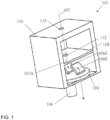
FIG. 1 : shows an unclaimed embodiment of the beam director receiving a vertical beam and the subsequent beam path. -
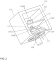
FIG. 2 : shows an unclaimed embodiment of the beam director receiving a horizontal beam and the path the beam follows. -
FIG. 3A : shows an unclaimed embodiment of the invention where the second reflector displaceable relative to the first reflector and the path the beam follows. -
FIG. 3B : shows a bottom view of the unclaimed embodiment inFIG.3A with a radial exit slit. -
FIG. 4 : shows another unclaimed embodiment of the invention receiving a horizontal beam and the path of the beam. -
FIG. 5 : shows another unclaimed embodiment of the invention with the beam source directed downwards inside the beam director. -
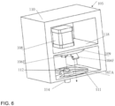
FIG. 6 : shows another unclaimed embodiment of the invention where the beam source is vertically directed upwards and attached to the beam director. -
FIG. 7 : shows the beam director installed in a 3-D printer. -
FIG. 8 : shows another unclaimed embodiment showing the mirrors connected by an arm. -
FIG. 9 : shows another unclaimed embodiment using a rhomboid prism. -
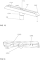
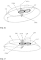
FIG. 10 : shows another embodiment with the second reflector being a slanted annular reflecting surface. -
FIG. 11 : shows another embodiment with cone reflector with variable radius actuator. -
FIG. 12 : shows another unclaimed embodiment with a double arm configuration. -
FIG. 13 : shows the double arm from underneath with index holes (notches). -
FIG. 14 : shows a block diagram of how the beam director can be controlled. -
FIG. 15 : shows a diagram of a simplified schematic for the index arm locator. -
FIG. 16 : shows another embodiment a slanted annular reflector enabling printing of full 360° -
FIG. 17 : shows another view ofFIG. 16 in an embodiment where printing of full 360° is possible. -
FIG. 18 : shows another embodiment of a slanted annular reflector enabling printing of full 360° utilizing prism as second reflector. -
FIG. 19 : shows another view ofFIG. 18 in an embodiment where printing of full 360° is possible. Utilizing prism as second reflector. -
FIG. 20 : shows another embodiment with cone reflector with variable radius actuator utilizing prism as second reflector and having 360° utilization. - The present invention will be described with reference to the drawings. Various refinements and substitutions are possible based on the principles and teachings herein.
- With reference to
FIG. 1 beam director 105 hashole 115 on top ofhousing 110 andfocus lens 112 located insupport 118.First mirror 106E which is located towards the center ofrotatable rotor disk 109.Rotor disk 109 is rotated bymotor 108.First mirror 106E is orientated towardssecond mirror 106F and so configured to reflect focusing (beam is set to focus on work surface)beam 107A towardssecond mirror 106F.Second mirror 106F is located towards the edge ofrotor disk 109 and mounted at an angle onrotor disk 109 and configured to reflect a beam towardswork surface 113 which in the case ofFIG. 7 is the build surface of a 3-D printer. - When activated
beam 107 entersbeam director 105 throughhole 115 and goes throughlens 112 to be focused. Focusingbeam 107A then strikesfirst mirror 106E.Motor 108 rotatesrotor disk 109 andfirst mirror 106E andsecond mirror 106F mounted onrotor disk 109. Focusingbeam 107A is then rotated and reflected towardssecond mirror 106F. Fromsecond 107A is then reflected vertically and then leavesmirror 106F beambeam director 105 through opening 111 as shown inFIG. 2 . Thebeam 107A then continues to thework surface 113 as shown inFIG. 7 the beam then following a curve path relative to the work surface and trace out an arc on the work surface. - In
FIG. 2 another embodiment ofbeam director 105 is shown. In thiscase beam director 105 has stationarythird mirror 106D mounted at an angle onsupport 118.Third mirror 106D is directed towardslens 112 and configured to reflecthorizontal beam 107 throughlens 112 towardsfirst mirror 106E. Oncethird mirror 106D reflectshorizontal beam 107 vertically towardssecond mirror 106E throughlens 112 focusingbeam 107A follows the same path as described above and also exitsbeam director 105 through opening 111. Thebeam 107A then continues to thework surface 113 as shown inFIG. 7 the beam then following a curve path relative to the work surface and trace out an arc on the work surface. - In
FIG. 3A the embodiment is shown with thehousing 110,third mirror 106D andsupport 118 withlens 112 removed to better illustrate a further feature of the invention. In this configurationsecond mirror 106F is adjustable relative tofirst mirror 106E. As is shown inFIG. 3A it is done withradial slide 116 driven byradial actuator 120. As can be seen inFIG. 3B focusing beam 107A exits through radial exit slit 117. By adjustment the distance thebeam 107A travels from the first to the second mirror is adjusted so that correspondingly due to the adjustment the focusingbeam 107A follows a curve path of adjustable radii relative to the work surface and trace out arcs of adjustable radii on thework surface 113 shown inFIG. 7 . To keep the beam focused on thebed 113 either thebeam 107A needs to be collimated or the cone angle should be 45 degrees. -
Figure 4 shows a another embodiment of the invention. In this case thebeam director 105 is orientated upside down if compared as inFIG. 2 withmotor 108 androtor disk 109 towards the top.Second mirror 106F is differently orientated as compared withsecond mirror 106F inFIG. 2 . InFIG. 4 second mirror 106F is toward the top and reflectsbeam 107 away fromrotor disk 109 downwards towardswork surface 113. - In
FIG. 5 third mirror 106D is removed. Thebeam source 114 is inside thebeam director 105 and is directed vertically downwards towardsfirst mirror 106E. The focusingbeam 107A then follows the same path in the print-head 105 as discussed above. - In
FIG. 6 is shownbeam director 105 similar to beam director shown inFIG. 5 . In this configurationthird mirror 106D is removed and a verticalexternal beam source 114 directed upwards towardsfirst mirror 106E and attachedhousing 110 ofbeam director 105. - An object that is created by a 3-D printer is composed of small sections of material that is heated by a beam that strikes the material. The material then hardens as the material cools down. This invention due to the spinning action of the mirrors and the beam then following a curve path relative to the work surface and trace out arcs on the work surface small curved sections can be created. By activating beam and deactivating beam (modulating the beam) the small curved sections can be used to build up a printed object.
- The modulation of the beam is done by computer control. A digital image of the object to be printed is loaded into the computer. The software in the computer then calculates the different subsequent layer patterns that has to be generated and printed in order to build up the object layer by layer.
- With reference to
FIG. 7 thebeam director 105 is used as a print-head for a three (3-D)printer 101 and is installed on a positioning system of a 3-D printer. The positioning system in this case is an actuator driven X-Y axis gantry system. First y-axis stage 104A and second y-axis stage 104B are both supported by twopillars 103 at their ends. Between the pillars 103 a work surface 113 (the build surface of the 3-D printer) is located. - The
x-axis stage 102 is perpendicular to first y-axis 104A and second y-axis stage 104B. Thex-axis stage 102 moves back and forth along the y-axis stages. Thebeam director 105 located on thex-axis stage 102 and moves back and forth along thex-axis stage 102. -
Bottom mirror 106A is located at the foot ofpillar 103 and is orientated at an angle towardstop mirror 106B and so configured to reflectbeam 107 towardstop mirror 106B which is located towards the top ofpillar 103.Top mirror 106B is configured to reflectbeam 107 towardsx-axis stage mirror 106C.X-axis stage mirror 106C is configured to reflect a beam towardsbeam director 105. - It should be appreciated that there are numerous other arrangements of mirrors by which
beam 107 can be directed towards the print head. - In this embodiment the
beam director 105 as illustrated inFIG. 2 is used as print-head. Thereforebeam 107 will therefore be directed towardsthird mirror 106D as shown inFIG. 2 . - With reference to
FIG. 7 when the beam source is activated thebeam 107 strikesbottom mirror 106A and is reflected upwards towardstop mirror 106B. Thebeam 107 is then reflected towardsx-stage mirror 106C bytop mirror 106B.X-stage mirror 106C then reflectsbeam 107 towardsthird mirror 106D ofbeam director 105 shown inFIG. 2 -
Beam 107 then follows the path inbeam director 105 ofFIG. 2 until focusingbeam 107A exitsbeam director 105 as shown inFIG 7 . - Focusing
beam 107A strikes the work surface 113 (build surface of the 3-D printer) atpoint 107B as shown inFIG. 7 . Sincefocused beam 107A is rotated byfirst mirror 106E thefocused beam 107A thus follows a curved path relative to the work surface and traces out an arc on thework surface 113. - After each rotation of
rotor disk 109, thebeam director 105 is moved by a beam width in the X-axis direction by the positioning system. The beam will now print a new curve next to the previous one. This will continue until the end of the object to be printed is reached in the X-axis direction. Thebeam director 105 will then be moved one curve width by the positioning system in the Y-axis direction. The beam director will then work its way back in the X-axis direction towards the opposite end of the object to be printed in the X-axis direction. Another aspect of the invention is to move X and Y simultaneously while theprint head 105 is printing. - Once again when this end is reached the beam director will again be moved one curve width in the Y-axis direction and once more move along the X-axis in the opposite direction. This to and fro print action is continued until a whole layer of the object is complete. When the first layer is completed the work surface (or build surface of a 3-D printer) will be lowered in the z-axis direction by a layer thickness, and a new layer of powder will dispense over the present layer and the print process will start again for the new layer. The object will therefore be constructed by the printing of subsequent layers on top of each other.
- In
FIG. 8 is shown another embodiment where instead of arotor disk 109 is used it is replaced with anarm 125.Arm 125 holdssecond mirror 106F horizontally in position relative tofirst mirror 106E. - In
FIG. 9 is shown that instead ofrotor disk 109rotor prism platform 121B on whichrhomboid prism 121A is mounted on, is used. The first angled prism side 106EP and second angled prism side 106FP in this case act as first andsecond mirrors - In
FIG. 10 is shownsecond mirror 106F has a slanted annular reflective surface 132 ( shaped similar to a horizontal slice out of a cone) which is supported by annularreflective surface member 131. Slanted annularreflective surface 132 horizontally encircles thefirst mirror 106E is stationary and has the same vertical axis as the rotational axis of thefirst mirror 106E.First mirror 106E is rotated bymotor 108 which is held in position bymotor support 133. Annularreflective surface 132 has a large diameter and a small diameter. The large diameter is directed towards the work surface, is at an angle relative to the rotational axis offirst mirror 106E and configured to reflect focusingbeam 107A vertically towards the work surface. When focusingbeam 107A strikesfirst mirror 106E andmotor 108 rotates thefirst mirror 106E,first mirror 106E rotates thebeam 107A as it rotates, and reflects the beam to slanted annularreflective surface 132 which reflects the focusingbeam 107A to the work surface; the beam then follows a curve path relative to the work surface and trace out an arc on the work surface. - In
FIG. 11 is an embodiment where thesecond mirror 106F is cone shaped andcone reflector 129A is the inner cone reflective surface of cone member 129.Cone reflector 129A encirclesfirst reflector 106E and has the same vertical axis as the rotational axis of thefirst mirror 106E. Thecone reflector 129A is rotationally stationary. The larger diameter ofcone reflector 129A is directed towards the work surface and configured to reflect a beam from the first reflector towards the work surface. - Cone member 129 has
support base 126 withfirst guide rod 127A, andsecond guide rod 127B.Thread rod 124 rests onsupport base 126.Motor support 133 holdsmotor 108 in place and hasfirst guide hole 128A through which guiderod 127A goes, second guide hole 128B through which guiderod 127B goes and threaded hole 128C through which threadedshaft 124 goes. The thread of threaded hole 128C engages the thread of threadedshaft 124. Cone motor 123 is connected to threadedshaft 124 and rotates threadedshaft 124.Motor 108 is connected to and rotatesfirst mirror 106E. - When cone motor 123 is activated threaded
rod 124 rotates and engages the thread of thread hole 128C and vertically displacescone reflector 129A relative tofirst mirror 106E, whileguide rods motor support 133. During displacement ofcone reflector 129A relativefirst mirror 106E the focusingbeam 107A strikes thecone reflector 129A and the distance (radius) focusingbeam 107A travels fromfirst mirror 106E tocone reflector 129A changes. Correspondingly the distance from the rotational axis offirst mirror 106E thatbeam 107A leaves cone member 129 changes. Focusingbeam 107A traces out arcs of varying radii on the work surface with the rotational axis offirst mirror 106E as the origin of the radii. To keep the beam focused on thebed 113 either thebeam 107A needs to be collimated or the cone angle should be 45 degrees. - In the preferred embodiment in
FIG. 12 vertical rotatablefirst mirror 106E is rotatable upon itself bymotor 108 and receives a vertical focusingbeam 107A.First mirror 106E rotates the vertical beam as it rotates and reflects the beam horizontally to asecond mirror 106F at the end ofarm 125.Arm 125 has opposing, stabilizing member, dummy arm 125A as a counter balance and to provide greater stability during rotation.Arms 125A and 125 are mounted on arm mount 125B.Second mirror 106F then reflects the focusingbeam 107A vertically towards thework surface 113 inFIG. 7 . - The
beam 107 can be of any wave length or type of ray for example laser, light, x-ray or an infra-red light beam. It could also be a particle beam for instance a molecule, atom, ion, proton, neutron, isotope, electron, or any other sub-atomic particle. - The
beam 107 could also be conveyed to thebeam director 105 from a beam source outside the beam director via a beam fibre. In this invention the print speed is to a great extent only limited by themotor 108 rotational speed. There is no stop start action causing acceleration and deceleration during which print time is lost. Since therotor disk 109,arm 125 on its own andarm 125 in combination with dummy arm 125A keeps rotating at a constant speed there is no need to slow down or reverse speed. - The print quality of the invention is improved as the beam strikes the work surface 113 (target) perpendicularly and therefore mitigating f-theta, galvanometer or/and polygon mirrors related errors.
- Some of f-theta errors occurs when a beam strikes the target surface at an angle. In scanning and printing systems where the beam is directed by deflecting it form a mirror towards the target, the beam strikes the target at an angle. This causes f-theta distortion where the beam diameter changes a from circle to an elliptic shape.
- Consider an ordinary lens with an imaginary lens axis in the same direction that the beam travels through the lens and the lens axis going through the centre of the lens. Define an angle between the lens axis and the path of a beam originating from the center of the lens as theta. In these ordinary lenses the focus length is in the form of a section of the surface of a sphere with the point where the axis goes through the lens as the origin of the sphere. If an image of the lens is projected on the inside surface of a sphere it will be in focus. This is because the path length that the beam follows at whatever the angle of theta will always be the same, as mentioned that being the radius of a sphere.
- However, if the image is projected on a flat surface it is a different matter. If an ordinary lens is directed towards a flat surface and the lens is focused in the region on the flat surface where the beam strikes the surface perpendicularly, the image will become more out of focus the further away you move from the point where the beam strikes the flat surface perpendicularly. That is as the angle theta increases the image will become more out of focus.
- The distance that the beam must travel to strike the flat surface increases as the angle of the beam between the axis of the lens and the path of the beam increases. That is as the angle theta increases the distance that the beam must travel also increases. As the path of the beam is longer it exceeds the lens's focal length. This results in an out of focus beam and image. This can be corrected with an F-theta lens. F-theta lenses are however expensive and the f-theta solution is not errors free.
- In this invention however the beam is directed orthogonally direct above the target. The path to the target remains constant and the beam is always in focus. There is therefore no need for an F-theta correcting lens and money is saved.
- Further, improvement of the print quality and speed is obtained by eliminating the galvanometer errors since the rotation of the
motor 108 is kept at a constant speed compared to a galvanometer reversal errors and positioning errors. - This invention can be implemented in 3-D printers, material cutters, material marking and scanners of many different configurations. For example it can be implemented in printers and scanners where movements and/or controls of the system are generally based on polar coordinates relative to a centre of a build surface. Components of these types of scanners and printers may generally include a rotatable build surface; a print/scan head positioned over the build surface; a positioning system coupled to the print/scan head and configured to move the print/scan head over the build surface based on polar coordinates relative to a centre.
- This invention has many further applications. For instance it can also be used to create cut-outs patterns in materials, marking of materials, sintering of materials, melting of materials, hardening of materials, engraving of materials, cladding of materials, lithographic plates and masks that can be used in the manufacture of electronics and electronic devices as for example integrated circuits. This invention could also be adapted to be used in ordinary 3-D printers with an X/Y positioning system and where the build-surface is a flat surface, displaced along the Z-axis towards and away from the print-head and the building material is deposited on the built surface and built up layer by layer.
- The housing of the beam director can be made of metal, plastic acrylic, glass or any strong suitable material. The beam director rotor can be made out of a light solid material or alloy such as aluminium, wood, glass, acrylic, abs, graphite, carbon-fiber or any suitable light material. When the beam director is made of glass, clear plastic or any suitable transparent material then a rhomboid prism can be incorporated into the structure as one piece and therefore, eliminating the need for mirrors.
- The reflectors are generally made of mirrors or polished material as aluminum, nickel and other suitable reflective material or prisms made of glass or plastic or similar material. The reflectors dimensions depends on the beam diameter. As an example a beam diameter of 3mm will require a mirror size of 4.5mm by 4.5mm, to accommodate the beam size.
- When a prism is made and cut as a rhomboid prism, the cross section dimension is generally in the order of about 50% larger than the beam diameter. Thus with a beam diameter of 3mm a rhomboid prism with a cross section of 5mm by 5mm is used. The length of the rhomboid prism will determine the radius of the arc that will be printed. As can be seen in
FIG. 9 , in the case of a rhomboid prism with a length of 40mm the path length of thebeam 107A will be 40mm. The radius of the arc that is printed is also 40mm. - The motor that can be used is a brush-less direct current (bldc) motor with tachometer output or hall effect feedback in order to stabilize the rotational speed. The output of the motor is influenced on the inertia of the rotor.
- The focus lens is type plano-convex or any other suitable type focus lens with focal length about 100 mm .
- The dimensions of the print-head is scalable and for this particular case as shown in
FIG. 1 andFIG.2 is: - 1. Height: 130 mm.
- 2. Width: 100 mm.
- 3. Depth: 100mm.
- 4. Diameter of disc: 80mm.
- 5. Thickness of disc: 3mm.
-
FIG. 15 shows how the index arm locator function is performed by using an integrated infrared emitter and detector in one package, the TCND5000 by VISHAY SEMICONDUCTOR. This is an infrared sensor detector combination that consists of a led emitter and a photo-diode. The Primary MPU (other than dedicated MPU based driver controller, discussed later) will monitor the output signals from the optics index locator. When no arm is present or when the detector faces the engraved notches 125D or 125E the output voltage will close to 0 volts and will be calculated by:
- When the detector faces the arm body then the reflective surface will increase the photo diode current using the same formula:

- //The photo diode current will exceed 10 micro ampere
In this case Vout will be about 5+. - When the rotor (double arm in this case) is rotating, the Primary MPU will read the signals and detect the pattern for the head or for the tail. In addition, the distance in time between the pulses will provide the rotor RPM.
- Calibration procedures for the Emitter and Receiver will enable a fine tuning of the monitoring of the arm by the Primary MPU overcoming data sheet specifications deviations. See reference
US patent application 14/538,924 . - R2 is setting the emitter current. Chosen to 870 ohm.
- C1 will reduce the noise. Chosen to 5PF; Please note: higher value for C1 may increase the respond time.
- AD8615 is a low offset current opamp (operational amplifier) by ANALOG DEVICES
- AGND is the circuit ground
- -Vs is the AD8615 negative power supply input
- +Vs is the AD8615 is the positive power supply input
- Although a full size rotor or one arm configuration may be employed, the double arm configuration in
FIG. 12 and FIG. 13 is more stable. It reduces the inertia and provides maximum speed, is symmetrical with respect to the rotational axis and therefore more balanced. The dummy arm 125A acts as a counter balance and provides stability during rotation. It lends itself to easy fabrication out of a variety of materials such as aluminium. InFIG. 12 reflectors - In
FIG. 13 is shown the double arm embodiment from beneath.Motor shaft socket 125C receives the shaft ofmotor 108. Index holes (notches) 125D and 125E are located inarms 125A and 125 respectively. They are used in combination with an index locator to determine the rotational position of the double arm. - A
motor 108 BLY174S-24V-12000 from ANAHEIM AUTOMATION can be used for a double arm (125 and 125A together) with a length of 30 mm. - As shown in
FIG. 14 the selected motor is a 3 phase bldc motor with hall effect sensors for better motor speed control. The motor is connected to the sensored bldc motor driver, such that it can detect the rotational speed of the motor and control the speed of the motor. The sensored bldc motor driver is also using micro processor unit (MPU), TMS320F28069M by TEXAS INSTRUMENT, INC. This allows for closed loop speed control of the motor. The TMS320F28069M MPU also drives the DRV8312 hardware driver, made by TEXAS INSTRUMENT, INC. The TMS320F28069M is a dedicated MPU, part of the motor driver, dedicated to maintain the close loop of the motor rotations per minutes. The motor index locator is an optical emitter and detector combination in one package the TCND5000 by VISHAY SEMICONDUCTOR. This is an infrared sensor detector combination that consists of a led emitter and a photo-diode delivering a response time of about 15 nanoseconds. The optical sensor will be positioned 6 mm from the rotating rotor. The sensor will detect the presence of an arm (125 or 125A) and the index holes (notches) 125D and 125E in the arm. - As shown further in
FIG. 14 the output signal of the motor index locator is connected to the primary MPU which will be read by the primary MPU. The primary MPU should be distinguished from the dedicated MPU part of the motor driver, dedicated to maintain the close loop of the motor rotations per minutes. The index locator provides the primary MPU with the rotational position of the double arm. Primary MPU is connected to the laser modulator that controls the firing of the laser. The primary MPU has a 3-D image of the object to be printed loaded in its memory. The primary MPU calculates or load a slice of the horizontal layers of the 3-D object that will be printed on top of each other to construct the 3-D object. - The primary MPU sends a signal to the sensored bldc motor driver to set the speed of the motor. It detects the position of the arm with the motor index locator. Using the location of the arm ( and the X/Y location of the print head) and the specific layer that needs to be printed, of the object to be printed, it generates an output signal to the laser modulator that fires the laser.
- A cheaper option will be to instead of using brush-less direct current (bldc) motor with tachometer output or hall effect feedback, is to use a stepper motor. This will eliminate the use of as discussed a sensored bldc motor driver, that can detect the rotational speed of the motor and control the speed of the motor. The stepper motor will also eliminate the need for an index locator.
- In
FIG. 16 annular reflectivereflective surface member 131 has bearing 136 at its center. Inside bearing 136hollow shaft 138 passes through and hasfirst mirror 106E mounted at an angle at its end as shown inFIG. 17 . Bearing 136 facilitates rotation ofhollow shaft 138.First mirror gear 138A meshes withmotor gear 137 and is attached to hollowshaft 138A.Motor gear 137 is connected to the shaft ofmotor 108 as seen inFIG. 16 . Inoperation motor 108 rotateshollow shaft 138A via meshing gears 137 and 138A.First mirror 106E rotates withhollow shaft 138A. Focusingbeam 107A entershollow shaft 138 and strikes rotatingfirst mirror 106E which rotatesbeam 107A and reflects it towards slanted annularreflective surface 132 which reflects focusingbeam 107A downwards towardswork surface 113 as shown inFIG. 7 . This embodiment makes printing of the full 360° is possible. - In
FIG. 18 annular reflectivereflective surface member 131 has bearing 136 at its center. Inside bearing 136hollow shaft 138 passes through and hasfirst mirror 106E mounted at an angle at its end as shown inFIG. 19 . Bearing 136 facilitates rotation ofhollow shaft 138.First mirror gear 138A meshes withmotor gear 137 and is attached to hollowshaft 138A.Motor gear 137 is connected to the shaft ofmotor 108 as seen inFIG. 18 . Inoperation motor 108 rotateshollow shaft 138A via meshing gears 137 and 138A.First mirror 106E rotates withhollow shaft 138A. Focusingbeam 107A entershollow shaft 138 and strikes rotatingfirst mirror 106E which rotatesbeam 107A and reflects it towards and throughprism wall 134 to reflectingprism wall 135 which reflects focusingbeam 107A downwards towardswork surface 113 as shown inFIG. 7 . This embodiment makes printing of the full 360° is possible. -
FIG. 20 shows an embodiment similar toFIG 11 . where a 360° scanning is achieved and where the second reflector is a cone shape prism, where 107A is reflected offmirror 106E and reflected towards and throughprism wall 134 then reflected off insideprism wall 135 towards and throughbottom prism wall 139. - Reflectors that can used include mirrors, prisms, crystals and other reflective elements. The reflectors can also be Incorporated in the housing of an aerodynamic member to facilitate the rotation and air flow over the reflectors. An example would be that of a disk shaped housing.
- Although the invention has been shown and described with respect of certain embodiments, it is obvious that equivalents and modifications will occur to others skilled in the art upon the reading and understanding of the specification. The present invention includes all such equivalents and modifications.
| Table with Reference Numerals and | ||
| 101 | 3-D printer. | |
| 102 | x-axis stage. | |
| 103 | pillar. | |
| 104A | first y-axis stage. | |
| 104B | second y-axis stage. | |
| 105 | | |
| | bottom mirror | |
| 106B | | |
| 106C | x-axis | |
| 106D | | |
| 106E | first mirror | |
| 106EP | first prism | |
| 106F | second mirror | |
| 106FP | second | |
| 107 | | |
| | focusing beam | |
| 107B | point where beam | |
| 108 | | |
| 109 | | |
| 110 | housing | |
| 111 | | |
| 112 | | |
| 113 | | |
| 114 | | |
| 115 | | |
| 116 | | |
| 117 | | |
| 118 | | |
| 120 | | |
| | rhomboid prism | |
| 121B | rotor prism platform | |
| 123 | | |
| 124 | threaded | |
| 125 | arm | |
| 125A | dummy arm | |
| | arm mount | |
| 125C | motor shaft socket | |
| 125D | index hole (notch) | |
| 125E | index hole (notch) | |
| 126 | | |
| 127A | | |
| 127B | | |
| 128A | first guide hole | |
| 128B | second guide hole | |
| 128C | threaded hole | |
| 129 | | |
| | cone reflector | |
| 131 | annular | |
| 132 | slanted annular | |
| 133 | | |
| 134 | inside | |
| 135 | | |
| 136 | bearing | |
| 137 | | |
| 138 | | |
| 138A | | |
| 139 | bottom prism wall | |
Claims (4)
- A three-dimensional printer (101), comprising:a work surface (113); a print head comprising a beam director (105);a positioning system (104A), (104B), (103) having positioned thereon the print head comprising the beam director, the positioning system being an actuator driven X-Y axis gantry system configured to move the print head over the work surface;wherein the beam director comprises:a beam source (114) for generating a beam (107A);a rotatable first reflector (106E) configured to receive the beam from the beam sourcewherein the print head is positioned such that the beam source is aligned with a rotational axis of the first relfector and the beam is received along the rotational axis of the first reflector;an actuator (108) for rotating the first reflector about the rotational axis, whereby the first reflector rotates the beam and reflects the beam at a constant angle to the rotational axis, wherein the actuator is positioned on and rotates about the rotational axis of the first reflector; anda second reflector (106F) constantly facing the first reflector at a constant angle; the second reflector configured to reflect the beam towards the work surface at a constant angle thereto, and an axis of the second reflector being aligned with the rotational axis of the first reflector,whereby when the beam is activated and the actuator rotates the first reflector, the beam strikes the rotating first reflector rotating and reflecting the beam to the second reflector, which reflects the beam to the work surface; the beam then following a curve path relative to the work surface and traces out an arc on the work surface;wherein the second reflector comprises a rotationally-stationary, slanted, annular reflecting surface (132), encircling the first reflector; the second reflector at an angle to the rotational axis of the first reflector; wherein the annular reflecting surface having a large diameter and a small diameter, the large diameter directed towards the work surface whereby when the beam is activated and the actuator rotates the first reflector; the vertical beam strikes the rotating first reflector rotating and reflecting the beam to the annular reflecting surface of the second reflector, which reflects the beam to the work surface.
- A printer as in claim 1 wherein the second reflector is configured to reflect the beam from the first reflector parallel to the rotational axis of first reflector and perpendicular to the work surface.
- A method of three-dimensional printing including directing a beam towards a work surface (113) with a beam director (105), the beam director forming part of a print head positioned on a positioning system (104A), (104B), (103) of a three-dimensional printer, the positioning system being an actuator driven X-Y axis gantry system configured to move the print head over the work surface, the method comprising:generating a beam (107A) with a beam source (114) of the beam director;rotating a first reflector (106E), of the beam director, about a rotational axis with an actuator (108), wherein the beam source and the beam are aligned with the rotational axis, and wherein the actuator is positioned on and rotates about the rotational axis of the first reflector;directing the beam towards the first reflector along the rotational axis of the first reflector;providing a second reflector (106F) constantly facing the first reflector at a constant angle as the first reflector rotates, wherein an axis of the second reflector is aligned with the rotational axis of the first reflector;reflecting the beam with the first reflector at a constant angle to the rotational axis towards the second reflector;reflecting the beam with the second reflector towards a work surface of the three-dimensional printer;so that when the beam is activated and the actuator rotates the first reflector; the beam strikes the rotating first reflector rotating the beam and reflecting the beam to the second reflector, which reflects the beam to the work surface at a constant angle thereto; the beam then following a curved path relative to the work surface and traces out an arc on the work surface;wherein the second reflector comprises a slanted annular reflecting surface (132) encircling the first reflector; being rotationally stationary and having a central axis the same as the rotational axis of the first reflector; wherein the annular reflecting surface includes a large diameter and a small diameter, the large diameter directed towards the work surface; so that when the beam is activated and the actuator rotates the first reflector; the vertical beam strikes the rotating first reflector rotating and reflecting the beam to the annular reflecting surface of the second reflector, which reflects the beam to the work surface; the beam then following a curve path relative to the work surface and tracing out an arc on the work surface.
- The method of claim 4, wherein the second reflector reflects the beam parallel to the rotational axis of first reflector and perpendicular to the work surface.
Priority Applications (1)
| Application Number | Priority Date | Filing Date | Title |
|---|---|---|---|
| HRP20231016TT HRP20231016T1 (en) | 2015-06-14 | 2016-06-13 | A beam director |
Applications Claiming Priority (3)
| Application Number | Priority Date | Filing Date | Title |
|---|---|---|---|
| US201562175402P | 2015-06-14 | 2015-06-14 | |
| US14/848,056 US9435998B1 (en) | 2015-06-14 | 2015-09-08 | Beam director |
| PCT/US2016/037131 WO2017052702A2 (en) | 2015-06-14 | 2016-06-13 | A beam director |
Publications (4)
| Publication Number | Publication Date |
|---|---|
| EP3308212A2 EP3308212A2 (en) | 2018-04-18 |
| EP3308212A4 EP3308212A4 (en) | 2019-03-06 |
| EP3308212B1 true EP3308212B1 (en) | 2023-06-07 |
| EP3308212C0 EP3308212C0 (en) | 2023-06-07 |
Family
ID=56878013
Family Applications (1)
| Application Number | Title | Priority Date | Filing Date |
|---|---|---|---|
| EP16849132.2A Active EP3308212B1 (en) | 2015-06-14 | 2016-06-13 | A beam director |
Country Status (17)
| Country | Link |
|---|---|
| US (1) | US9435998B1 (en) |
| EP (1) | EP3308212B1 (en) |
| JP (1) | JP6869900B2 (en) |
| KR (2) | KR20190067826A (en) |
| CN (1) | CN107850773B (en) |
| AU (1) | AU2016325992B2 (en) |
| BR (1) | BR112017026606B1 (en) |
| CA (1) | CA2983200C (en) |
| EA (1) | EA034729B1 (en) |
| ES (1) | ES2958307T3 (en) |
| HR (1) | HRP20231016T1 (en) |
| IL (1) | IL256310B (en) |
| MX (1) | MX2017016129A (en) |
| MY (1) | MY181975A (en) |
| PH (1) | PH12017502210B1 (en) |
| PL (1) | PL3308212T3 (en) |
| WO (1) | WO2017052702A2 (en) |
Families Citing this family (16)
| Publication number | Priority date | Publication date | Assignee | Title |
|---|---|---|---|---|
| CA3037375C (en) * | 2016-09-26 | 2021-07-20 | Charles BIBAS | Beam manipulation system |
| US10416444B2 (en) * | 2016-11-03 | 2019-09-17 | Charles Bibas | Beam director with improved optics |
| JP2021523293A (en) * | 2018-05-09 | 2021-09-02 | アプライド マテリアルズ インコーポレイテッドApplied Materials,Incorporated | Additional manufacturing using polygon scanner |
| CN109175364B (en) * | 2018-09-28 | 2020-02-21 | 江苏大学 | A laser additive device and method for additive manufacturing thereof |
| ES3056290T3 (en) * | 2020-02-25 | 2026-02-19 | Charles Bibas | Enhanced beam director with improved optics |
| TWI723836B (en) * | 2020-04-08 | 2021-04-01 | 宏碁股份有限公司 | Optical projection system |
| CN112178574B (en) * | 2020-10-10 | 2022-06-14 | 上海观池聚光数字科技有限公司 | Optical-mechanical module and arrangement method thereof |
| CN112799220B (en) * | 2021-01-25 | 2022-06-14 | 厦门大学 | Laser confocal emergent adapter |
| WO2022178575A1 (en) * | 2021-02-24 | 2022-09-01 | Baraja Pty Ltd | An optical beam director |
| CN117677877A (en) * | 2021-05-28 | 2024-03-08 | 恩耐公司 | Rotary beam switch |
| CN113117606B (en) * | 2021-05-28 | 2022-07-15 | 中国科学技术大学 | A beam source manipulator that precisely adjusts the direction and position of the beam source in a vacuum beam source cavity |
| CN113534427A (en) * | 2021-07-14 | 2021-10-22 | 西安粼粼光电科技有限公司 | Optical early warning tracking platform based on quick reflector array and working method |
| CN114147364A (en) * | 2021-11-15 | 2022-03-08 | 合肥泰沃达智能装备有限公司 | Rotary laser micro-carving equipment for light guide plate |
| CN115008026A (en) * | 2022-05-23 | 2022-09-06 | 合肥泰沃达智能装备有限公司 | A light guide plate processing device based on array rotation |
| CN115891176B (en) * | 2022-12-06 | 2025-09-19 | 杭州爱新凯科技有限公司 | Laser 3D printing mobile scanning method |
| CN116699794B (en) * | 2023-08-09 | 2023-10-24 | 南京佰福激光技术有限公司 | Device and method for assembling light guide arm lens |
Citations (2)
| Publication number | Priority date | Publication date | Assignee | Title |
|---|---|---|---|---|
| DE595822C (en) * | 1932-02-10 | 1934-10-31 | Curt Bamberger Dr | Device for recording and reproducing sound films |
| JPH01237123A (en) * | 1988-03-17 | 1989-09-21 | Mitsui Eng & Shipbuild Co Ltd | Light flux scanning method in optical shaping method |
Family Cites Families (23)
| Publication number | Priority date | Publication date | Assignee | Title |
|---|---|---|---|---|
| JPS5742637Y2 (en) * | 1977-05-21 | 1982-09-20 | ||
| JPS6023114Y2 (en) * | 1982-07-30 | 1985-07-09 | 工業技術院長 | Laser processing aiming device |
| US4688201A (en) * | 1985-01-16 | 1987-08-18 | Hewlett-Packard Company | Focusing and tracking apparatus for an optical data storage device |
| DE8601209U1 (en) * | 1986-01-20 | 1989-05-24 | Birkle, Gebhard, 7750 Konstanz | Device for optical scanning of objects |
| US4699447A (en) * | 1986-02-27 | 1987-10-13 | Spectra-Physics, Inc. | Optical beam scanner with rotating mirror |
| US5214528A (en) * | 1990-09-14 | 1993-05-25 | Konica Corporation | Optical beam scanning apparatus |
| JP2944000B2 (en) * | 1991-01-14 | 1999-08-30 | 日本電信電話株式会社 | 3D object forming equipment |
| JP2912721B2 (en) * | 1991-02-19 | 1999-06-28 | 日本電信電話株式会社 | 3D object formation method |
| GB9127241D0 (en) * | 1991-12-23 | 1992-02-19 | Crosfield Electronics Ltd | Light deflecting device |
| EP0551666B1 (en) * | 1992-01-14 | 1996-07-10 | Opticon Sensors Europe B.V. | Optical scanner |
| JPH06114950A (en) * | 1992-10-01 | 1994-04-26 | Shiimetsuto Kk | Light curing modeling equipment |
| US5434696A (en) * | 1993-09-27 | 1995-07-18 | Watson; Troy M. | Active energy diametric scanning |
| US5897798A (en) * | 1997-06-04 | 1999-04-27 | Hmt Technology Corporation | Laser texturing apparatus employing a rotating mirror |
| US6275626B1 (en) * | 1998-10-26 | 2001-08-14 | Herzel Laor | 1xN reflector switch |
| US6466352B1 (en) * | 1999-04-23 | 2002-10-15 | Arie Shahar | High-resolution reading and writing scan system for planar and cylindrical surfaces |
| JP2000330042A (en) * | 1999-05-18 | 2000-11-30 | Shuukou Denki Kk | Optical path switching device |
| DE102004058263A1 (en) * | 2004-12-03 | 2006-06-08 | Rehau Ag + Co | Device for guiding a beam, in particular a laser beam, device for optical processing, in particular for laser processing, and method for guiding a beam, in particular a laser beam |
| US20080116183A1 (en) * | 2006-11-21 | 2008-05-22 | Palo Alto Research Center Incorporated | Light Scanning Mechanism For Scan Displacement Invariant Laser Ablation Apparatus |
| JP5469674B2 (en) * | 2008-12-05 | 2014-04-16 | マイクロニック マイデータ アーベー | Method and system for writing on a workpiece |
| US20110216401A1 (en) * | 2010-03-03 | 2011-09-08 | Palo Alto Research Center Incorporated | Scanning System With Orbiting Objective |
| WO2014074954A2 (en) * | 2012-11-08 | 2014-05-15 | Suman Das | Systems and methods for fabricating three-dimensional objects |
| JP5602913B2 (en) * | 2013-07-04 | 2014-10-08 | パナソニック株式会社 | Manufacturing method of three-dimensional shaped object and three-dimensional shaped object obtained therefrom |
| CN203636210U (en) * | 2013-12-31 | 2014-06-11 | 南京斯托克机器人系统有限公司 | Laser cutting head |
-
2015
- 2015-09-08 US US14/848,056 patent/US9435998B1/en active Active
-
2016
- 2016-06-13 JP JP2017563347A patent/JP6869900B2/en not_active Expired - Fee Related
- 2016-06-13 EA EA201890040A patent/EA034729B1/en unknown
- 2016-06-13 MX MX2017016129A patent/MX2017016129A/en active IP Right Grant
- 2016-06-13 KR KR1020197012340A patent/KR20190067826A/en not_active Withdrawn
- 2016-06-13 KR KR1020187001119A patent/KR20180016596A/en not_active Ceased
- 2016-06-13 PL PL16849132.2T patent/PL3308212T3/en unknown
- 2016-06-13 WO PCT/US2016/037131 patent/WO2017052702A2/en not_active Ceased
- 2016-06-13 BR BR112017026606A patent/BR112017026606B1/en active IP Right Grant
- 2016-06-13 MY MYPI2017704601A patent/MY181975A/en unknown
- 2016-06-13 CA CA2983200A patent/CA2983200C/en active Active
- 2016-06-13 HR HRP20231016TT patent/HRP20231016T1/en unknown
- 2016-06-13 CN CN201680030655.0A patent/CN107850773B/en active Active
- 2016-06-13 AU AU2016325992A patent/AU2016325992B2/en not_active Ceased
- 2016-06-13 ES ES16849132T patent/ES2958307T3/en active Active
- 2016-06-13 EP EP16849132.2A patent/EP3308212B1/en active Active
-
2017
- 2017-12-04 PH PH12017502210A patent/PH12017502210B1/en unknown
- 2017-12-14 IL IL256310A patent/IL256310B/en active IP Right Grant
Patent Citations (2)
| Publication number | Priority date | Publication date | Assignee | Title |
|---|---|---|---|---|
| DE595822C (en) * | 1932-02-10 | 1934-10-31 | Curt Bamberger Dr | Device for recording and reproducing sound films |
| JPH01237123A (en) * | 1988-03-17 | 1989-09-21 | Mitsui Eng & Shipbuild Co Ltd | Light flux scanning method in optical shaping method |
Also Published As
| Publication number | Publication date |
|---|---|
| MX2017016129A (en) | 2018-04-18 |
| EP3308212A2 (en) | 2018-04-18 |
| EP3308212A4 (en) | 2019-03-06 |
| US9435998B1 (en) | 2016-09-06 |
| KR20180016596A (en) | 2018-02-14 |
| IL256310A (en) | 2018-02-28 |
| CA2983200A1 (en) | 2017-03-30 |
| WO2017052702A3 (en) | 2017-12-14 |
| AU2016325992B2 (en) | 2018-11-15 |
| KR20190067826A (en) | 2019-06-17 |
| JP2018520379A (en) | 2018-07-26 |
| CA2983200C (en) | 2020-07-28 |
| EA034729B1 (en) | 2020-03-13 |
| ES2958307T3 (en) | 2024-02-07 |
| WO2017052702A2 (en) | 2017-03-30 |
| BR112017026606B1 (en) | 2019-08-27 |
| CN107850773A (en) | 2018-03-27 |
| PH12017502210B1 (en) | 2021-09-22 |
| BR112017026606A2 (en) | 2018-08-14 |
| PL3308212T3 (en) | 2023-10-23 |
| MY181975A (en) | 2021-01-17 |
| PH12017502210A1 (en) | 2018-06-11 |
| WO2017052702A4 (en) | 2018-01-18 |
| HRP20231016T1 (en) | 2023-12-08 |
| JP6869900B2 (en) | 2021-05-12 |
| EA201890040A1 (en) | 2018-05-31 |
| CN107850773B (en) | 2019-04-09 |
| EP3308212C0 (en) | 2023-06-07 |
| IL256310B (en) | 2018-05-31 |
| AU2016325992A1 (en) | 2018-02-01 |
Similar Documents
| Publication | Publication Date | Title |
|---|---|---|
| CA2983200C (en) | A beam director | |
| CN104959730B (en) | Rotary table femtosecond laser direct-write methods and device | |
| US4838631A (en) | Laser beam directing system | |
| JP2008215829A (en) | Calibration tool, calibration method, and laser machining device using method | |
| KR20220146323A (en) | Adjustment method of laser machining apparatus, and laser machining apparatus | |
| CN1145540C (en) | Laser processing apparatus | |
| JP3365388B2 (en) | Laser processing optics | |
| KR20200140213A (en) | Apparatus for automatically correcting the position of laser scanning system | |
| CN115943056A (en) | Laser Array Position Detection | |
| US5307198A (en) | Scanner with combined predictive and diffractive feedback control of beam position | |
| JP2005262260A (en) | Laser beam machining apparatus and laser beam machining control program | |
| JPH0687097B2 (en) | Passive reflective surface tracking laser raster scanner | |
| CN103809288A (en) | Laser scanning method, device and imaging equipment | |
| JP2709949B2 (en) | Drawing surface adjustment mechanism of scanning type drawing device | |
| JPH0222928B2 (en) | ||
| CN220178393U (en) | Automatic mark head is beaten in focusing | |
| KR20210020451A (en) | Laser processign apparatus and laser processing method | |
| KR20190122515A (en) | Apparatus for automatically correcting the position of laser scanning system | |
| JP2009128499A (en) | Laser direct drawing method and laser direct drawing device | |
| JP2007229744A (en) | Laser beam machining method and apparatus | |
| JP4505854B2 (en) | Laser processing equipment | |
| CN116460423A (en) | A laser three-dimensional dynamic focusing system and working method based on diffractive optical elements | |
| CN116203527A (en) | Laser scanning equipment, security system and scanning control method | |
| CN115026313A (en) | Double-laser single-galvanometer printing system and printing method | |
| JPH10325929A (en) | Optical scanner |
Legal Events
| Date | Code | Title | Description |
|---|---|---|---|
| REG | Reference to a national code |
Ref country code: HR Ref legal event code: TUEP Ref document number: P20231016T Country of ref document: HR |
|
| STAA | Information on the status of an ep patent application or granted ep patent |
Free format text: STATUS: THE INTERNATIONAL PUBLICATION HAS BEEN MADE |
|
| PUAI | Public reference made under article 153(3) epc to a published international application that has entered the european phase |
Free format text: ORIGINAL CODE: 0009012 |
|
| STAA | Information on the status of an ep patent application or granted ep patent |
Free format text: STATUS: REQUEST FOR EXAMINATION WAS MADE |
|
| 17P | Request for examination filed |
Effective date: 20180109 |
|
| AK | Designated contracting states |
Kind code of ref document: A2 Designated state(s): AL AT BE BG CH CY CZ DE DK EE ES FI FR GB GR HR HU IE IS IT LI LT LU LV MC MK MT NL NO PL PT RO RS SE SI SK SM TR |
|
| AX | Request for extension of the european patent |
Extension state: BA ME |
|
| RIN1 | Information on inventor provided before grant (corrected) |
Inventor name: ZHOU, NIANQUING Inventor name: HUGO, DEON Inventor name: BIBAS, CHARLES |
|
| DAV | Request for validation of the european patent (deleted) | ||
| DAX | Request for extension of the european patent (deleted) | ||
| A4 | Supplementary search report drawn up and despatched |
Effective date: 20190131 |
|
| RIC1 | Information provided on ipc code assigned before grant |
Ipc: G02B 26/08 20060101AFI20190125BHEP Ipc: B41J 2/44 20060101ALI20190125BHEP Ipc: G02B 26/10 20060101ALI20190125BHEP Ipc: B41J 3/407 20060101ALI20190125BHEP |
|
| STAA | Information on the status of an ep patent application or granted ep patent |
Free format text: STATUS: EXAMINATION IS IN PROGRESS |
|
| 17Q | First examination report despatched |
Effective date: 20210617 |
|
| GRAP | Despatch of communication of intention to grant a patent |
Free format text: ORIGINAL CODE: EPIDOSNIGR1 |
|
| STAA | Information on the status of an ep patent application or granted ep patent |
Free format text: STATUS: GRANT OF PATENT IS INTENDED |
|
| INTG | Intention to grant announced |
Effective date: 20221019 |
|
| GRAS | Grant fee paid |
Free format text: ORIGINAL CODE: EPIDOSNIGR3 |
|
| RAP3 | Party data changed (applicant data changed or rights of an application transferred) |
Owner name: BIBAS, CHARLES |
|
| GRAA | (expected) grant |
Free format text: ORIGINAL CODE: 0009210 |
|
| STAA | Information on the status of an ep patent application or granted ep patent |
Free format text: STATUS: THE PATENT HAS BEEN GRANTED |
|
| AK | Designated contracting states |
Kind code of ref document: B1 Designated state(s): AL AT BE BG CH CY CZ DE DK EE ES FI FR GB GR HR HU IE IS IT LI LT LU LV MC MK MT NL NO PL PT RO RS SE SI SK SM TR |
|
| REG | Reference to a national code |
Ref country code: GB Ref legal event code: FG4D |
|
| REG | Reference to a national code |
Ref country code: CH Ref legal event code: EP Ref country code: AT Ref legal event code: REF Ref document number: 1576850 Country of ref document: AT Kind code of ref document: T Effective date: 20230615 |
|
| REG | Reference to a national code |
Ref country code: DE Ref legal event code: R096 Ref document number: 602016080138 Country of ref document: DE |
|
| U01 | Request for unitary effect filed |
Effective date: 20230707 |
|
| U07 | Unitary effect registered |
Designated state(s): AT BE BG DE DK EE FI FR IT LT LU LV MT NL PT SE SI Effective date: 20230720 |
|
| REG | Reference to a national code |
Ref country code: RO Ref legal event code: EPE |
|
| REG | Reference to a national code |
Ref country code: LT Ref legal event code: MG9D |
|
| PG25 | Lapsed in a contracting state [announced via postgrant information from national office to epo] |
Ref country code: NO Free format text: LAPSE BECAUSE OF FAILURE TO SUBMIT A TRANSLATION OF THE DESCRIPTION OR TO PAY THE FEE WITHIN THE PRESCRIBED TIME-LIMIT Effective date: 20230907 |
|
| PGFP | Annual fee paid to national office [announced via postgrant information from national office to epo] |
Ref country code: TR Payment date: 20230904 Year of fee payment: 8 Ref country code: RO Payment date: 20230912 Year of fee payment: 8 Ref country code: ES Payment date: 20230914 Year of fee payment: 8 Ref country code: CH Payment date: 20230831 Year of fee payment: 8 |
|
| U20 | Renewal fee for the european patent with unitary effect paid |
Year of fee payment: 8 Effective date: 20231017 |
|
| REG | Reference to a national code |
Ref country code: HR Ref legal event code: ODRP Ref document number: P20231016T Country of ref document: HR Payment date: 20231117 Year of fee payment: 8 |
|
| PG25 | Lapsed in a contracting state [announced via postgrant information from national office to epo] |
Ref country code: RS Free format text: LAPSE BECAUSE OF FAILURE TO SUBMIT A TRANSLATION OF THE DESCRIPTION OR TO PAY THE FEE WITHIN THE PRESCRIBED TIME-LIMIT Effective date: 20230607 Ref country code: GR Free format text: LAPSE BECAUSE OF FAILURE TO SUBMIT A TRANSLATION OF THE DESCRIPTION OR TO PAY THE FEE WITHIN THE PRESCRIBED TIME-LIMIT Effective date: 20230908 |
|
| REG | Reference to a national code |
Ref country code: HR Ref legal event code: T1PR Ref document number: P20231016 Country of ref document: HR |
|
| PG25 | Lapsed in a contracting state [announced via postgrant information from national office to epo] |
Ref country code: SK Free format text: LAPSE BECAUSE OF FAILURE TO SUBMIT A TRANSLATION OF THE DESCRIPTION OR TO PAY THE FEE WITHIN THE PRESCRIBED TIME-LIMIT Effective date: 20230607 |
|
| PG25 | Lapsed in a contracting state [announced via postgrant information from national office to epo] |
Ref country code: IS Free format text: LAPSE BECAUSE OF FAILURE TO SUBMIT A TRANSLATION OF THE DESCRIPTION OR TO PAY THE FEE WITHIN THE PRESCRIBED TIME-LIMIT Effective date: 20231007 |
|
| PG25 | Lapsed in a contracting state [announced via postgrant information from national office to epo] |
Ref country code: SM Free format text: LAPSE BECAUSE OF FAILURE TO SUBMIT A TRANSLATION OF THE DESCRIPTION OR TO PAY THE FEE WITHIN THE PRESCRIBED TIME-LIMIT Effective date: 20230607 Ref country code: SK Free format text: LAPSE BECAUSE OF FAILURE TO SUBMIT A TRANSLATION OF THE DESCRIPTION OR TO PAY THE FEE WITHIN THE PRESCRIBED TIME-LIMIT Effective date: 20230607 Ref country code: IS Free format text: LAPSE BECAUSE OF FAILURE TO SUBMIT A TRANSLATION OF THE DESCRIPTION OR TO PAY THE FEE WITHIN THE PRESCRIBED TIME-LIMIT Effective date: 20231007 Ref country code: CZ Free format text: LAPSE BECAUSE OF FAILURE TO SUBMIT A TRANSLATION OF THE DESCRIPTION OR TO PAY THE FEE WITHIN THE PRESCRIBED TIME-LIMIT Effective date: 20230607 |
|
| PGFP | Annual fee paid to national office [announced via postgrant information from national office to epo] |
Ref country code: HR Payment date: 20231117 Year of fee payment: 8 |
|
| REG | Reference to a national code |
Ref country code: ES Ref legal event code: FG2A Ref document number: 2958307 Country of ref document: ES Kind code of ref document: T3 Effective date: 20240207 |
|
| REG | Reference to a national code |
Ref country code: DE Ref legal event code: R097 Ref document number: 602016080138 Country of ref document: DE |
|
| PG25 | Lapsed in a contracting state [announced via postgrant information from national office to epo] |
Ref country code: MC Free format text: LAPSE BECAUSE OF FAILURE TO SUBMIT A TRANSLATION OF THE DESCRIPTION OR TO PAY THE FEE WITHIN THE PRESCRIBED TIME-LIMIT Effective date: 20230607 |
|
| PG25 | Lapsed in a contracting state [announced via postgrant information from national office to epo] |
Ref country code: MC Free format text: LAPSE BECAUSE OF FAILURE TO SUBMIT A TRANSLATION OF THE DESCRIPTION OR TO PAY THE FEE WITHIN THE PRESCRIBED TIME-LIMIT Effective date: 20230607 |
|
| PLBE | No opposition filed within time limit |
Free format text: ORIGINAL CODE: 0009261 |
|
| STAA | Information on the status of an ep patent application or granted ep patent |
Free format text: STATUS: NO OPPOSITION FILED WITHIN TIME LIMIT |
|
| 26N | No opposition filed |
Effective date: 20240308 |
|
| PGFP | Annual fee paid to national office [announced via postgrant information from national office to epo] |
Ref country code: IE Payment date: 20240613 Year of fee payment: 9 |
|
| U20 | Renewal fee for the european patent with unitary effect paid |
Year of fee payment: 9 Effective date: 20240613 |
|
| PGFP | Annual fee paid to national office [announced via postgrant information from national office to epo] |
Ref country code: PL Payment date: 20230906 Year of fee payment: 8 |
|
| U1N | Appointed representative for the unitary patent procedure changed after the registration of the unitary effect |
Representative=s name: VALET PATENT SERVICES LIMITED; DE |
|
| REG | Reference to a national code |
Ref country code: HR Ref legal event code: PBON Ref document number: P20231016 Country of ref document: HR Effective date: 20240613 |
|
| PG25 | Lapsed in a contracting state [announced via postgrant information from national office to epo] |
Ref country code: RO Free format text: LAPSE BECAUSE OF NON-PAYMENT OF DUE FEES Effective date: 20240613 |
|
| PG25 | Lapsed in a contracting state [announced via postgrant information from national office to epo] |
Ref country code: RO Free format text: LAPSE BECAUSE OF NON-PAYMENT OF DUE FEES Effective date: 20240613 |
|
| REG | Reference to a national code |
Ref country code: CH Ref legal event code: PL |
|
| PG25 | Lapsed in a contracting state [announced via postgrant information from national office to epo] |
Ref country code: HR Free format text: LAPSE BECAUSE OF NON-PAYMENT OF DUE FEES Effective date: 20240613 |
|
| PG25 | Lapsed in a contracting state [announced via postgrant information from national office to epo] |
Ref country code: CH Free format text: LAPSE BECAUSE OF NON-PAYMENT OF DUE FEES Effective date: 20240630 |
|
| U20 | Renewal fee for the european patent with unitary effect paid |
Year of fee payment: 10 Effective date: 20250605 |
|
| PGFP | Annual fee paid to national office [announced via postgrant information from national office to epo] |
Ref country code: GB Payment date: 20250403 Year of fee payment: 10 |
|
| PG25 | Lapsed in a contracting state [announced via postgrant information from national office to epo] |
Ref country code: CY Free format text: LAPSE BECAUSE OF FAILURE TO SUBMIT A TRANSLATION OF THE DESCRIPTION OR TO PAY THE FEE WITHIN THE PRESCRIBED TIME-LIMIT; INVALID AB INITIO Effective date: 20160613 |
|
| REG | Reference to a national code |
Ref country code: ES Ref legal event code: FD2A Effective date: 20250731 |
|
| PG25 | Lapsed in a contracting state [announced via postgrant information from national office to epo] |
Ref country code: HU Free format text: LAPSE BECAUSE OF FAILURE TO SUBMIT A TRANSLATION OF THE DESCRIPTION OR TO PAY THE FEE WITHIN THE PRESCRIBED TIME-LIMIT; INVALID AB INITIO Effective date: 20160613 |
|
| PG25 | Lapsed in a contracting state [announced via postgrant information from national office to epo] |
Ref country code: ES Free format text: LAPSE BECAUSE OF NON-PAYMENT OF DUE FEES Effective date: 20240614 |
|
| PG25 | Lapsed in a contracting state [announced via postgrant information from national office to epo] |
Ref country code: PL Free format text: LAPSE BECAUSE OF NON-PAYMENT OF DUE FEES Effective date: 20240613 |
|
| PG25 | Lapsed in a contracting state [announced via postgrant information from national office to epo] |
Ref country code: IE Free format text: LAPSE BECAUSE OF NON-PAYMENT OF DUE FEES Effective date: 20250613 |
|
| U20 | Renewal fee for the european patent with unitary effect paid |
Year of fee payment: 11 Effective date: 20260408 |