EP3308017B1 - Wind turbine having an identity marker arrangement - Google Patents
Wind turbine having an identity marker arrangement Download PDFInfo
- Publication number
- EP3308017B1 EP3308017B1 EP16727943.9A EP16727943A EP3308017B1 EP 3308017 B1 EP3308017 B1 EP 3308017B1 EP 16727943 A EP16727943 A EP 16727943A EP 3308017 B1 EP3308017 B1 EP 3308017B1
- Authority
- EP
- European Patent Office
- Prior art keywords
- wind turbine
- tiles
- display surface
- marker arrangement
- character
- Prior art date
- Legal status (The legal status is an assumption and is not a legal conclusion. Google has not performed a legal analysis and makes no representation as to the accuracy of the status listed.)
- Active
Links
Images

Classifications
-
- F—MECHANICAL ENGINEERING; LIGHTING; HEATING; WEAPONS; BLASTING
- F03—MACHINES OR ENGINES FOR LIQUIDS; WIND, SPRING, OR WEIGHT MOTORS; PRODUCING MECHANICAL POWER OR A REACTIVE PROPULSIVE THRUST, NOT OTHERWISE PROVIDED FOR
- F03D—WIND MOTORS
- F03D80/00—Details, components or accessories not provided for in groups F03D1/00 - F03D17/00
- F03D80/10—Arrangements for warning air traffic
-
- F—MECHANICAL ENGINEERING; LIGHTING; HEATING; WEAPONS; BLASTING
- F03—MACHINES OR ENGINES FOR LIQUIDS; WIND, SPRING, OR WEIGHT MOTORS; PRODUCING MECHANICAL POWER OR A REACTIVE PROPULSIVE THRUST, NOT OTHERWISE PROVIDED FOR
- F03D—WIND MOTORS
- F03D80/00—Details, components or accessories not provided for in groups F03D1/00 - F03D17/00
-
- G—PHYSICS
- G09—EDUCATION; CRYPTOGRAPHY; DISPLAY; ADVERTISING; SEALS
- G09F—DISPLAYING; ADVERTISING; SIGNS; LABELS OR NAME-PLATES; SEALS
- G09F9/00—Indicating arrangements for variable information in which the information is built-up on a support by selection or combination of individual elements
- G09F9/30—Indicating arrangements for variable information in which the information is built-up on a support by selection or combination of individual elements in which the desired character or characters are formed by combining individual elements
- G09F9/302—Indicating arrangements for variable information in which the information is built-up on a support by selection or combination of individual elements in which the desired character or characters are formed by combining individual elements characterised by the form or geometrical disposition of the individual elements
-
- F—MECHANICAL ENGINEERING; LIGHTING; HEATING; WEAPONS; BLASTING
- F05—INDEXING SCHEMES RELATING TO ENGINES OR PUMPS IN VARIOUS SUBCLASSES OF CLASSES F01-F04
- F05B—INDEXING SCHEME RELATING TO WIND, SPRING, WEIGHT, INERTIA OR LIKE MOTORS, TO MACHINES OR ENGINES FOR LIQUIDS COVERED BY SUBCLASSES F03B, F03D AND F03G
- F05B2220/00—Application
- F05B2220/25—Application as advertisement
-
- F—MECHANICAL ENGINEERING; LIGHTING; HEATING; WEAPONS; BLASTING
- F05—INDEXING SCHEMES RELATING TO ENGINES OR PUMPS IN VARIOUS SUBCLASSES OF CLASSES F01-F04
- F05B—INDEXING SCHEME RELATING TO WIND, SPRING, WEIGHT, INERTIA OR LIKE MOTORS, TO MACHINES OR ENGINES FOR LIQUIDS COVERED BY SUBCLASSES F03B, F03D AND F03G
- F05B2240/00—Components
- F05B2240/10—Stators
- F05B2240/14—Casings, housings, nacelles, gondels or the like, protecting or supporting assemblies there within
-
- F—MECHANICAL ENGINEERING; LIGHTING; HEATING; WEAPONS; BLASTING
- F05—INDEXING SCHEMES RELATING TO ENGINES OR PUMPS IN VARIOUS SUBCLASSES OF CLASSES F01-F04
- F05B—INDEXING SCHEME RELATING TO WIND, SPRING, WEIGHT, INERTIA OR LIKE MOTORS, TO MACHINES OR ENGINES FOR LIQUIDS COVERED BY SUBCLASSES F03B, F03D AND F03G
- F05B2240/00—Components
- F05B2240/99—Components characterised by colour or colour patterns
-
- Y—GENERAL TAGGING OF NEW TECHNOLOGICAL DEVELOPMENTS; GENERAL TAGGING OF CROSS-SECTIONAL TECHNOLOGIES SPANNING OVER SEVERAL SECTIONS OF THE IPC; TECHNICAL SUBJECTS COVERED BY FORMER USPC CROSS-REFERENCE ART COLLECTIONS [XRACs] AND DIGESTS
- Y02—TECHNOLOGIES OR APPLICATIONS FOR MITIGATION OR ADAPTATION AGAINST CLIMATE CHANGE
- Y02B—CLIMATE CHANGE MITIGATION TECHNOLOGIES RELATED TO BUILDINGS, e.g. HOUSING, HOUSE APPLIANCES OR RELATED END-USER APPLICATIONS
- Y02B10/00—Integration of renewable energy sources in buildings
- Y02B10/30—Wind power
-
- Y—GENERAL TAGGING OF NEW TECHNOLOGICAL DEVELOPMENTS; GENERAL TAGGING OF CROSS-SECTIONAL TECHNOLOGIES SPANNING OVER SEVERAL SECTIONS OF THE IPC; TECHNICAL SUBJECTS COVERED BY FORMER USPC CROSS-REFERENCE ART COLLECTIONS [XRACs] AND DIGESTS
- Y02—TECHNOLOGIES OR APPLICATIONS FOR MITIGATION OR ADAPTATION AGAINST CLIMATE CHANGE
- Y02E—REDUCTION OF GREENHOUSE GAS [GHG] EMISSIONS, RELATED TO ENERGY GENERATION, TRANSMISSION OR DISTRIBUTION
- Y02E10/00—Energy generation through renewable energy sources
- Y02E10/70—Wind energy
- Y02E10/72—Wind turbines with rotation axis in wind direction
Definitions
- the invention relates to an identity marker arrangement that is particularly, though not exclusively, suited to use on a nacelle of a wind turbine.
- wind turbine arrays which are also referred to as a wind farms or wind parks. This enables the wind park operator to take advantage of economies of scale for installation and maintenance purposes, for example.
- the nacelles of wind turbines are sometimes accessed by helicopter in order for maintenance to be carried out. This is particularly the case in offshore wind parks in which aerial access is much more cost-effective since maintenance personnel can be delivered to a specific wind turbine with suitable tools and components at a relatively low cost.
- a drawback of this approach to marking a nacelle is that the ID plates are typically large and unwieldy items that are difficult to fit in the gusty conditions common to wind turbine sites, so it is usually preferable to fit them prior to installation.
- the individual wind turbines of a wind park are allocated identification numbers only after the wind turbines have been installed, for example during a commissioning exercise. It will be appreciated therefore, that it may not be practical to install ID plates on nacelles at this point. So a solution is required to enable identification numbers to be applied to wind turbines after commissioning but in a way that is practical in the extreme weather conditions usually encountered at nacelle-height.
- embodiments of the invention provide a wind turbine ID marker arrangement to enable a wind turbine installation to be identified from the air, the ID marker arrangement comprising a display surface to which a pattern of tiles are removably attached.
- the tiles are small and portable, the tiles can be configured into a recognisable pattern, for example an alphanumeric character or, indeed, a plurality of such characters, easily by maintenance personnel after the wind turbine has been erected on site.
- the tiles are removably attached to the display surface in a way which is non- penetrative, as would be the case of fasteners such as bolts. This avoid the need for fixing holes in the display surface holes which, in the context of a wind turbine nacelle, for example, would not be desirable since they would potentially weaken its structure, would possibly also allow salt-laden air into the interior of the nacelle, and would also compromise the environmental control within the nacelle.
- the pattern of tiles will be configurable to display an ID character, e.g. an alphanumeric character
- Various fastening means may be provided to removably attach the tiles onto the display surface.
- the fastening means does not require penetration of the underlying display surface, which means that the structural integrity of the display surface is unaffected.
- One example of such a fastening means is an adhesive.
- the fastening means could be a non-removable adhesive which sticks securely once the tiles are applied to the display surface.
- a removable adhesive would be appropriate where the pattern of tiles is configured in a subtractive process in which selected tiles are removed from an array of tiles attached to the display surface so as to leave a character on the display surface.
- a mechanical fastening system such as a hook and loop fastening system, may be used instead of an adhesive.
- the tiles may be coloured so as to contrast with the display surface that acts as a backdrop for the tiles.
- a high degree of contrast may be preferable to maximise visibility in poor conditions.
- the display surface may be any outward facing surface of a wind turbine installation such as the tower or the nacelle, or any other ancillary structure of the wind turbine such as foundation, in the context of an offshore installation. Accordingly, the invention extends to a wind turbine component including an ID marker arrangement. Furthermore, the invention covers ID marker arrangement applied to other parts of the installation such as electrical substations and building that contain electrical equipment.
- the invention resides in a method of providing a visual ID marker arrangement on a wind turbine installation, comprising providing a display surface associated with the wind turbine installation, the display surface carrying a plurality of tiles arranged in an array; and removing selected ones of the plurality of tiles from the array in order to form a pattern of a recognisable character.
- the invention resides in a method of providing a visual ID marker arrangement on a wind turbine installation, comprising providing a display surface associated with the wind turbine installation; and attaching a plurality of tiles onto the display surface to form a pattern of tiles in the shape of a recognisable character.
- ID plates that are secured onto the nacelle of a particular wind turbine.
- Such an ID plate will typically display any suitable ID scheme that is required to identify the particular turbine to which it is attached, such ID schemes being proprietary to the manufacturer of the wind turbine.
- ID schemes being proprietary to the manufacturer of the wind turbine.
- the invention provides a solution to this issue, in the form of a configurable ID marker that can be configured after the wind turbine has been installed.
- the marking arrangement takes the form of elements or tiles that are arranged in an array on a display surface of the wind turbine the array being configurable so that the elements are formed into a pattern defining a recognisable character, insignia or indicia.
- the display surface is an upper surface of a nacelle of a wind turbine.
- a wind turbine installation 2 includes a wind turbine nacelle or 'module' 4 mounted on top of a tower 6 which is itself fixed into a foundation 8 in the usual manner.
- the wind turbine module 4 houses and supports the various power generating components of the wind turbine installation 2, one of which is a rotor 10 comprising a hub 12 and three blades 14 that define a rotor disc 16.
- the wind turbine installation shown in Figure 2 is a horizontal axis wind turbine (HAWT) which is a common type of system, although other types exist, to which the invention is also applicable.
- HAWT horizontal axis wind turbine
- the flow of wind acting on the blades 14 spins the rotor 10 which drives the power generation equipment housed in the wind turbine module 4.
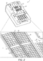
- the wind turbine module 4 is shown in more detail in Figure 2 , in which a region is shown enlarged in the inset panel. It should be appreciated that in this view, the wind turbine module 4 is shown without the rotor 10 attached to it, so as not to obscure necessary detail. From now on, the wind turbine module 4 will be referred to as the nacelle.
- the nacelle 4 is box-like in form and is generally rectangular in plan profile. This provides the nacelle 4 with a large upper surface or 'roof' 20 which acts as a display surface 22.
- the display surface 22 carries an ID marker arrangement 24 which is configurable to display one or more alphanumeric characters in a colour that contrasts with the surrounding region of the display surface 22 that provides a backdrop so that the ID marker arrangement 24 can be seen clearly from the air.
- the ID marker arrangement 24 includes five character arrays 26, although the invention is applicable to a single character array carried on the display surface 22. Only two of the five character arrays 26 are labelled on Figure 2 for clarity.
- Each of the character arrays 26 comprises an array of elements 28 that are arranged in rows and columns to form the array 26 which is rectangular in shape, in this embodiment. As will be explained, each of the elements 28 is flat and rectangular in form in the manner of a tile, and will be referred to as such from now on.
- each character array 26 is configurable into a pattern that defines a recognisable character, and such an array size is considered to be sufficient for the character to be discernible from the air.
- the dimensions of the character array satisfy the legal requirements that the height of characters should be greater than 1.5m, in the UK, and greater than 1.2m, elsewhere in Europe.
- the tiles 28 are formed from a suitable polymeric material such as vinylor polyurethane (PU).
- PU vinylor polyurethane
- Each tile 28 is provided with a coloured upper surface so as to contrast with the display surface 22 of the nacelle 4.
- the tiles 28 carry an adhesive layer, so that each tile 28 is like a sticker.
- adhesive it is envisaged that other means could be used, such as a hook and loop fastening system, either applied to the entirety of the reverse side of the tile 28, or in discrete patches.
- a heavy duty type system would be preferred due to the environmental conditions in which it would be expected to perform.
- the tiles 28 may be applied to the display surface 22 individually during the manufacture of the nacelle 4.
- the character array 26 could be applied as a single sticker-like unit in which the tiles 28 are provided as pre-cut forms which could then be removed as needed. This would simplify procedure of applying the character array 26 to the display surface 22.
- the individual tiles 28 could be delimited by suitable lines of weakness, for example lines of perforations, score lines and the like, which would enable selected tiles 28 to be separated out of the unit.
- the tile 28 is flexible so that it can be laid on the display surface and pressed into position so that the adhesive fixes the tile 28 in place.
- the display surface 22 is generally flat, but has a degree of curvature, particularly across the width of the surface. Therefore, the flexibility of the tiles 28 allow them to conform to the underlying profile of the display surface 22, thereby accommodating any ridges 31 or troughs 32 in the surface, as shown in Figure 2 by way of example.
- the tiles 28 could be substantially rigid, and therefore made out of a suitable rigid polymer such as polycarbonate (PC) or polypropylene (PP).
- PC polycarbonate
- PP polypropylene
- the tiles 28 will be secured to the display surface 22 by way of an adhesive
- the tiles 28 could be secured to the display surface 22 by way of releasably lockable mechanical fasteners such as quick-release latch pins, push pins or poppers, or even a hook and loop fastening arrangement.
- fasteners such as bolts.
- penetrative fasteners many holes would need to be formed into the display surface 22 to allow all of the tiles 28 to be fixed to it. Such holes would not be desirable since they would potentially weaken the structure of the display surface 22, but would also act as an ingress point to the outside environment, thus allowing salt-laden air into the interior of the nacelle.
- the tiles 28 are removable from the display surface 22, selected ones of the tiles 28 may be removed by maintenance personnel so that the remaining tiles form a recognisable distinguishing pattern, mark, insignia or indicia.
- the mark may be anything that enables the wind turbine to be distinguished from other wind turbines, although it is envisaged that alphanumeric characters are most suitable.
- each of the character arrays 26 has been configured to result in a string of recognisable alphanumeric characters so as to define a wind turbine ID number, which in this example is "ABC12".
- the process of configuring the character arrays 26 is essentially 'subtractive', in that selected tiles 28 are removed from the arrays in order to leave behind a pattern forming a recognisable character.
- a container could, for example, be located on the nacelle 4, in which the tiles 28 could be placed once they have been removed from the display surface 22. The tiles 28 could then be reused in the event that the character array 26 needed to be reconfigured.
- the maintenance personnel do not, therefore, need to carry away with them any of the tiles 28 and they could be left on the nacelle 4, suitably contained in appropriate weatherproof environment.
- the invention could also be embodied in an 'additive' process in which tiles are fixed to a predetermined grid, pattern or 'blank' array in order to build up the required character.
- One potential downside of this approach is that potentially a large number of tiles 28 would have to be carried onto the nacelle 4 in order to configure the character array with the required character.
- this issue could be resolved by providing a store of tiles 28 on or in the nacelle 4 in a suitable container ready to be applied by maintenance personnel.
- the means by which the tiles 28 are fastened to the display surface 22 may be permanent, for example an adhesive that provides a permanent bond, rather than a releasable one, or mechanical fasteners such as snap fixings or rivets which provide a non-releasable fixing.
- the term 'array' shall be considered to mean the plurality of tiles 28 arranged in rows and columns, e.g. as in Figure 2 , from which selected tiles may be removed to form a character, but also to the configuration of tiles that define the character, either by way of a subtractive process or an additive process, as has been described here.
- the tiles 28 have been described as generally flat rectangular elements that can be removed from or applied to the character array. It should be noted that this configuration of tile 28 is provided by way of example only, and that other forms are envisaged.
- the tiles 28 could be non-rectangular shapes, such as circular tiles.
- the tiles 28 need not be flat.
- the tiles could be shaped with a suitable form which would allow them to fit onto a complementary form defined on the display surface.
- One way of doing this would be to provide the underside of the tile with one or more protrusions, nodes, ridges or other form of locating feature that would mate with a suitable inverse mating feature provided on or defined by the display surface.
- Those locating features could interlock, either permanently or releasably, to hold the tiles 28 in place.
- the ID marker arrangement was defined on a display surface of the nacelle, it should be noted that this is not essential and the ID marker arrangement could in principle be provided in any position where it is visible to others, preferably from the air.
- it may be mounted on a platform or gantry associated with the nacelle, for instance a helipad or walkway.
- the display surface could be part of the tower itself, a suitable component associated with the tower, such as a maintenance platform, or the display surface could be part of a foundation of the wind turbine installation, for example a 'jacket' or 'tripod' foundation in an offshore wind turbine installation.
- the display surface could be part of a component unrelated to the wind turbine, for example it could be part of a housing for a transformer station or met station in a wind park.
- the display surface can be considered to be provided on a wind turbine component, whether or not it is part of the nacelle or tower explicitly.
Landscapes
- Engineering & Computer Science (AREA)
- Life Sciences & Earth Sciences (AREA)
- Sustainable Development (AREA)
- Sustainable Energy (AREA)
- Chemical & Material Sciences (AREA)
- Combustion & Propulsion (AREA)
- Mechanical Engineering (AREA)
- General Engineering & Computer Science (AREA)
- Physics & Mathematics (AREA)
- General Physics & Mathematics (AREA)
- Theoretical Computer Science (AREA)
- Wind Motors (AREA)
Description
- The invention relates to an identity marker arrangement that is particularly, though not exclusively, suited to use on a nacelle of a wind turbine.
- Commercial scale wind turbines are usually grouped together into wind turbine arrays, which are also referred to as a wind farms or wind parks. This enables the wind park operator to take advantage of economies of scale for installation and maintenance purposes, for example.
- The nacelles of wind turbines are sometimes accessed by helicopter in order for maintenance to be carried out. This is particularly the case in offshore wind parks in which aerial access is much more cost-effective since maintenance personnel can be delivered to a specific wind turbine with suitable tools and components at a relatively low cost.
- In order for maintenance personnel to be delivered to the correct wind turbine, it is of course necessary for wind turbines to be identifiable from the air. Therefore, it is known for the nacelles of wind turbines to be fitted with an ID plate which displays a suitable ID mark in large-enough characters so that it can be read at a distance by aircrew, see for instance: "Siemens signs long-term service extension for Rhyl Flats offshore wind farm in North Wales", Renewable energy focus.com, 27 March 2015.
- However, a drawback of this approach to marking a nacelle is that the ID plates are typically large and unwieldy items that are difficult to fit in the gusty conditions common to wind turbine sites, so it is usually preferable to fit them prior to installation. However, it may be the case that the individual wind turbines of a wind park are allocated identification numbers only after the wind turbines have been installed, for example during a commissioning exercise. It will be appreciated therefore, that it may not be practical to install ID plates on nacelles at this point. So a solution is required to enable identification numbers to be applied to wind turbines after commissioning but in a way that is practical in the extreme weather conditions usually encountered at nacelle-height.
- It is against this background that the invention has been devised.
- In a first aspect, embodiments of the invention provide a wind turbine ID marker arrangement to enable a wind turbine installation to be identified from the air, the ID marker arrangement comprising a display surface to which a pattern of tiles are removably attached.
- A benefit of the invention is that since the tiles are small and portable, the tiles can be configured into a recognisable pattern, for example an alphanumeric character or, indeed, a plurality of such characters, easily by maintenance personnel after the wind turbine has been erected on site. Advantageously, the tiles are removably attached to the display surface in a way which is non- penetrative, as would be the case of fasteners such as bolts. This avoid the need for fixing holes in the display surface holes which, in the context of a wind turbine nacelle, for example, would not be desirable since they would potentially weaken its structure, would possibly also allow salt-laden air into the interior of the nacelle, and would also compromise the environmental control within the nacelle.
- Although in principle the invention could be used to configure the pattern of tiles into any chosen shape, it is envisaged that the pattern of tiles will be configurable to display an ID character, e.g. an alphanumeric character
Various fastening means may be provided to removably attach the tiles onto the display surface. Preferably, the fastening means does not require penetration of the underlying display surface, which means that the structural integrity of the display surface is unaffected. One example of such a fastening means is an adhesive. - If the pattern of tiles is configured in an additive process in which selected tiles are attached to the display surface so as to define a character, the fastening means could be a non-removable adhesive which sticks securely once the tiles are applied to the display surface. Alternatively, a removable adhesive would be appropriate where the pattern of tiles is configured in a subtractive process in which selected tiles are removed from an array of tiles attached to the display surface so as to leave a character on the display surface.
- A mechanical fastening system, such as a hook and loop fastening system, may be used instead of an adhesive.
- In order to maximise the visibility of the pattern, the tiles may be coloured so as to contrast with the display surface that acts as a backdrop for the tiles. A high degree of contrast may be preferable to maximise visibility in poor conditions.
- In the above embodiments, the display surface may be any outward facing surface of a wind turbine installation such as the tower or the nacelle, or any other ancillary structure of the wind turbine such as foundation, in the context of an offshore installation. Accordingly, the invention extends to a wind turbine component including an ID marker arrangement. Furthermore, the invention covers ID marker arrangement applied to other parts of the installation such as electrical substations and building that contain electrical equipment.
- In another aspect, the invention resides in a method of providing a visual ID marker arrangement on a wind turbine installation, comprising providing a display surface associated with the wind turbine installation, the display surface carrying a plurality of tiles arranged in an array; and removing selected ones of the plurality of tiles from the array in order to form a pattern of a recognisable character.
- Conversely, in another aspect, the invention resides in a method of providing a visual ID marker arrangement on a wind turbine installation, comprising providing a display surface associated with the wind turbine installation; and attaching a plurality of tiles onto the display surface to form a pattern of tiles in the shape of a recognisable character.
- So that it may be more fully understood, the invention will now be described by way of example only to the following drawings, in which:
-
Figure 1 is a front view of a wind turbine installation; -
Figure 2 is a perspective view of the nacelle of the wind turbine installation ofFigure 1 , which shows an ID marker arrangement in accordance with an embodiment of the invention; -
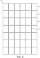
Figure 3 is a view of a single character array of the ID marker arrangement shown inFigure 2 ; -
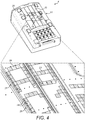
Figure 4 is a perspective view like that inFigure 2 , but which show the ID marker arrangement configured to display an identity number. - There is a need for wind turbine installations to be identifiable from the air. Primarily, this is so that aircrew on board helicopters are able to identify individual wind turbine installations out of the many that typically make up a wind park.
- Up to now, this requirement has been satisfied by the use of ID plates that are secured onto the nacelle of a particular wind turbine. Such an ID plate will typically display any suitable ID scheme that is required to identify the particular turbine to which it is attached, such ID schemes being proprietary to the manufacturer of the wind turbine. The blustery conditions prevalent at wind turbine sites, however, make these ID plates difficult to retrofit to a wind turbine after installation.
- The invention provides a solution to this issue, in the form of a configurable ID marker that can be configured after the wind turbine has been installed.
- The marking arrangement takes the form of elements or tiles that are arranged in an array on a display surface of the wind turbine the array being configurable so that the elements are formed into a pattern defining a recognisable character, insignia or indicia. Preferably the display surface is an upper surface of a nacelle of a wind turbine.
- With reference to
Figure 1 , a wind turbine installation 2 includes a wind turbine nacelle or 'module' 4 mounted on top of atower 6 which is itself fixed into afoundation 8 in the usual manner. Thewind turbine module 4 houses and supports the various power generating components of the wind turbine installation 2, one of which is arotor 10 comprising ahub 12 and threeblades 14 that define arotor disc 16. The wind turbine installation shown inFigure 2 is a horizontal axis wind turbine (HAWT) which is a common type of system, although other types exist, to which the invention is also applicable. As is known, the flow of wind acting on theblades 14 spins therotor 10 which drives the power generation equipment housed in thewind turbine module 4. - The
wind turbine module 4 is shown in more detail inFigure 2 , in which a region is shown enlarged in the inset panel. It should be appreciated that in this view, thewind turbine module 4 is shown without therotor 10 attached to it, so as not to obscure necessary detail. From now on, thewind turbine module 4 will be referred to as the nacelle. - The
nacelle 4 is box-like in form and is generally rectangular in plan profile. This provides thenacelle 4 with a large upper surface or 'roof' 20 which acts as adisplay surface 22. - The
display surface 22 carries anID marker arrangement 24 which is configurable to display one or more alphanumeric characters in a colour that contrasts with the surrounding region of thedisplay surface 22 that provides a backdrop so that theID marker arrangement 24 can be seen clearly from the air. - In this embodiment, the
ID marker arrangement 24 includes fivecharacter arrays 26, although the invention is applicable to a single character array carried on thedisplay surface 22. Only two of the fivecharacter arrays 26 are labelled onFigure 2 for clarity. Each of thecharacter arrays 26 comprises an array ofelements 28 that are arranged in rows and columns to form thearray 26 which is rectangular in shape, in this embodiment. As will be explained, each of theelements 28 is flat and rectangular in form in the manner of a tile, and will be referred to as such from now on. - The separation between each of the
tiles 28 can be seen inFigure 2 , but is shown more clearly inFigure 3 . Thecharacter array 26 in this Figure is given as an example, but it should be appreciated that other configurations would also be acceptable. - In the
rectangular array 26 ofFigure 3 , there are seven rows and five (7x5) columns oftiles 28, providing a total of thirty-fivetiles 28. Only three tiles are labelled for clarity. Eachtile 28 is approximately 18cm in width and approximately 21cm in height, and is separated from adjacent tiles by a5mm margin 30. This arrangement provides the character array with an overall dimension of approximately 1.5m in height and 90cm in width. As will be appreciated, eachcharacter array 26 is configurable into a pattern that defines a recognisable character, and such an array size is considered to be sufficient for the character to be discernible from the air. In this specific embodiment, the dimensions of the character array satisfy the legal requirements that the height of characters should be greater than 1.5m, in the UK, and greater than 1.2m, elsewhere in Europe. Notwithstanding this, it is envisaged that characters less than 1m in height (and approximately 600mm (0.6m) in width) would not be practical for this purpose, and so this represents an approximate minimum height limit for a character. Thus configuring an array in a rectilinear form having seven rows and five columns provides that all letters of the alphabet and numbers through 0-9 can be accurately defined. It is envisaged that a lower 'resolution' of the character array, for example six rows by four (6x4) columns, would be acceptable, and would possibly be easier to configure into a character, although it would might negatively affect readability of those characters. Conversely, it is also envisaged that an array having a higher resolution, for example nine rows by seven (9x7) columns, would also be acceptable, and would provide a cleaner looking character, albeit at the expense of the greater time required to configure the array into the desired shape. In summary, it is considered that a 7x5 array size strikes the right compromise between these factors. - Considering the envisaged minimum height limit for the characters of approximately 1mm, and the envisaged maximum practical resolution (9x7) for the character arrays, this would provide a minimum height for a tile of approximately 11cm (110mm) and a minimum width of approximately 0.85cm (85mm).
- In this embodiment, the
tiles 28 are formed from a suitable polymeric material such as vinylor polyurethane (PU). Eachtile 28 is provided with a coloured upper surface so as to contrast with thedisplay surface 22 of thenacelle 4. On their bottom surface, thetiles 28 carry an adhesive layer, so that eachtile 28 is like a sticker. As an alternative to adhesive, it is envisaged that other means could be used, such as a hook and loop fastening system, either applied to the entirety of the reverse side of thetile 28, or in discrete patches. A heavy duty type system would be preferred due to the environmental conditions in which it would be expected to perform. - The
tiles 28 may be applied to thedisplay surface 22 individually during the manufacture of thenacelle 4. Alternatively, it is envisaged that thecharacter array 26 could be applied as a single sticker-like unit in which thetiles 28 are provided as pre-cut forms which could then be removed as needed. This would simplify procedure of applying thecharacter array 26 to thedisplay surface 22. In such a unit, theindividual tiles 28 could be delimited by suitable lines of weakness, for example lines of perforations, score lines and the like, which would enable selectedtiles 28 to be separated out of the unit. - The
tile 28 is flexible so that it can be laid on the display surface and pressed into position so that the adhesive fixes thetile 28 in place. As can be seen inFigure 2 , thedisplay surface 22 is generally flat, but has a degree of curvature, particularly across the width of the surface. Therefore, the flexibility of thetiles 28 allow them to conform to the underlying profile of thedisplay surface 22, thereby accommodating anyridges 31 ortroughs 32 in the surface, as shown inFigure 2 by way of example. It will be appreciated that if thedisplay surface 22 was completely flat, then it would be acceptable for thetiles 28 to be substantially rigid, and therefore made out of a suitable rigid polymer such as polycarbonate (PC) or polypropylene (PP). In such a case, it is envisaged that thetiles 28 being rigid, could form part of a larger panel (not shown) defining thecharacter array 26, eachtile 28 being separable from the panel, without damaging itsadjacent tiles 28. - Although it is envisaged that the
tiles 28 will be secured to thedisplay surface 22 by way of an adhesive, embodiments are envisaged in which another form of temporary fixing will be used. For example, thetiles 28 could be secured to thedisplay surface 22 by way of releasably lockable mechanical fasteners such as quick-release latch pins, push pins or poppers, or even a hook and loop fastening arrangement. It should be noted that all of these means of fastening thetiles 28 to thedisplay surface 22 are non-penetrative, as would be the case of fasteners such as bolts. To use such penetrative fasteners, many holes would need to be formed into thedisplay surface 22 to allow all of thetiles 28 to be fixed to it. Such holes would not be desirable since they would potentially weaken the structure of thedisplay surface 22, but would also act as an ingress point to the outside environment, thus allowing salt-laden air into the interior of the nacelle. - Since the
tiles 28 are removable from thedisplay surface 22, selected ones of thetiles 28 may be removed by maintenance personnel so that the remaining tiles form a recognisable distinguishing pattern, mark, insignia or indicia. In theory, the mark may be anything that enables the wind turbine to be distinguished from other wind turbines, although it is envisaged that alphanumeric characters are most suitable. - With this in mind, reference is made to
Figure 4 , in which it can be seen that each of thecharacter arrays 26 has been configured to result in a string of recognisable alphanumeric characters so as to define a wind turbine ID number, which in this example is "ABC12". - In the embodiments described above, the process of configuring the
character arrays 26 is essentially 'subtractive', in that selectedtiles 28 are removed from the arrays in order to leave behind a pattern forming a recognisable character. This confers some advantages; for instance the maintenance personnel would simply have to remove the pre-selected tiles and discard them in some way. A container could, for example, be located on thenacelle 4, in which thetiles 28 could be placed once they have been removed from thedisplay surface 22. Thetiles 28 could then be reused in the event that thecharacter array 26 needed to be reconfigured. The maintenance personnel do not, therefore, need to carry away with them any of thetiles 28 and they could be left on thenacelle 4, suitably contained in appropriate weatherproof environment. - However, it is envisaged that the invention could also be embodied in an 'additive' process in which tiles are fixed to a predetermined grid, pattern or 'blank' array in order to build up the required character. One potential downside of this approach is that potentially a large number of
tiles 28 would have to be carried onto thenacelle 4 in order to configure the character array with the required character. However, this issue could be resolved by providing a store oftiles 28 on or in thenacelle 4 in a suitable container ready to be applied by maintenance personnel. In such an additive tile configuration, the means by which thetiles 28 are fastened to thedisplay surface 22 may be permanent, for example an adhesive that provides a permanent bond, rather than a releasable one, or mechanical fasteners such as snap fixings or rivets which provide a non-releasable fixing. In the above description, it will be appreciated therefore that the term 'array' shall be considered to mean the plurality oftiles 28 arranged in rows and columns, e.g. as inFigure 2 , from which selected tiles may be removed to form a character, but also to the configuration of tiles that define the character, either by way of a subtractive process or an additive process, as has been described here. - In the above embodiments, the
tiles 28 have been described as generally flat rectangular elements that can be removed from or applied to the character array. It should be noted that this configuration oftile 28 is provided by way of example only, and that other forms are envisaged. For example, thetiles 28 could be non-rectangular shapes, such as circular tiles. - Also, the
tiles 28 need not be flat. For instance, the tiles could be shaped with a suitable form which would allow them to fit onto a complementary form defined on the display surface. One way of doing this would be to provide the underside of the tile with one or more protrusions, nodes, ridges or other form of locating feature that would mate with a suitable inverse mating feature provided on or defined by the display surface. Those locating features could interlock, either permanently or releasably, to hold thetiles 28 in place. - Some alternative embodiments have been explained above. However, the skilled person would understand that further variations and modifications may be made to the embodiments without going beyond the scope of the invention as defined by the claims, some example of which will now be explained.
- Although in the embodiments described above, the ID marker arrangement was defined on a display surface of the nacelle, it should be noted that this is not essential and the ID marker arrangement could in principle be provided in any position where it is visible to others, preferably from the air. For example, it may be mounted on a platform or gantry associated with the nacelle, for instance a helipad or walkway. Still further, the display surface could be part of the tower itself, a suitable component associated with the tower, such as a maintenance platform, or the display surface could be part of a foundation of the wind turbine installation, for example a 'jacket' or 'tripod' foundation in an offshore wind turbine installation. Still further the display surface could be part of a component unrelated to the wind turbine, for example it could be part of a housing for a transformer station or met station in a wind park.
- In all of these variants, the display surface can be considered to be provided on a wind turbine component, whether or not it is part of the nacelle or tower explicitly.
Claims (16)
- A wind turbine ID marker arrangement to enable a wind turbine installation to be identified from the air, the ID marker arrangement being characterized by comprising a display surface to which a pattern of tiles are removably attached.
- The wind turbine ID marker arrangement of claim 1, wherein the pattern of tiles are removably attached to the display surface by a fastening means.
- The wind turbine ID marker arrangement of claim 2, wherein the fastening means is an adhesive, such as a releasable adhesive.
- The wind turbine ID marker arrangement of claim 2, wherein the fastening means is a mechanical fastening system, such as releasable mechanical fastening system.
- The wind turbine ID marker arrangement of claim 4, wherein the mechanical fastening system is a hook and loop fastening system.
- The wind turbine ID marker arrangement of claims 1 to 5, wherein the tiles are coloured so as to contrast with the display surface that acts as a backdrop for the tiles.
- The wind turbine ID marker arrangement of claims 1 to 6, wherein the pattern of tiles is configurable to display an ID character.
- The wind turbine ID marker arrangement of claim 7, wherein the pattern of tiles is configurable in a subtractive process in which selected tiles are removed from an array of tiles attached to the display surface so as to leave a character on the display surface.
- The wind turbine ID marker arrangement of claim 7, wherein the pattern of tiles is configurable in an additive process in which selected tiles are attached to the display surface so as to define a character.
- The wind turbine ID marker arrangement of claim 8 or 9, wherein the array is a rectilinear array having an array size between 6 rows by 4 columns and 9 rows by 7 columns, such as wherein the array has an array size of 7 rows by 5 columns.
- The wind turbine ID marker arrangement of claims 7 to 10, wherein the character defines a minimum character height of 1000mm, such as a minimum character height of 1200mm or 1500mm.
- The wind turbine ID marker arrangement of claims 7 to 10, wherein the tiles have a minimum tile height of 110mm, such as a minimum tile height of 200mm.
- The wind turbine ID marker arrangement of any preceding claim, including one or more further patterns of tiles removably attached to the display surface.
- A wind turbine component including an ID marker arrangement as claimed in any of claims 1 to 13.
- A method of providing a visual ID marker arrangement on a wind turbine installation, characterized by
providing a display surface associated with the wind turbine installation, the display surface carrying a plurality of tiles arranged in an array;
removing selected ones of the plurality of tiles from the array in order to form a pattern of a recognisable character. - A method of providing a visual ID marker arrangement on a wind turbine installation, characterized by
providing a display surface associated with the wind turbine installation;
attaching a plurality of tiles onto the display surface to form a pattern of tiles in the shape of a recognisable character.
Priority Applications (1)
| Application Number | Priority Date | Filing Date | Title |
|---|---|---|---|
| PL16727943T PL3308017T3 (en) | 2015-06-12 | 2016-05-31 | Wind turbine having an identity marker arrangement |
Applications Claiming Priority (2)
| Application Number | Priority Date | Filing Date | Title |
|---|---|---|---|
| DKPA201570365 | 2015-06-12 | ||
| PCT/DK2016/050158 WO2016198073A1 (en) | 2015-06-12 | 2016-05-31 | Wind turbine having an identity marker arrangement |
Publications (2)
| Publication Number | Publication Date |
|---|---|
| EP3308017A1 EP3308017A1 (en) | 2018-04-18 |
| EP3308017B1 true EP3308017B1 (en) | 2019-07-10 |
Family
ID=56116168
Family Applications (1)
| Application Number | Title | Priority Date | Filing Date |
|---|---|---|---|
| EP16727943.9A Active EP3308017B1 (en) | 2015-06-12 | 2016-05-31 | Wind turbine having an identity marker arrangement |
Country Status (8)
| Country | Link |
|---|---|
| US (1) | US10443578B2 (en) |
| EP (1) | EP3308017B1 (en) |
| JP (1) | JP6743060B2 (en) |
| KR (1) | KR102056623B1 (en) |
| CN (1) | CN107787407B (en) |
| DK (1) | DK3308017T3 (en) |
| PL (1) | PL3308017T3 (en) |
| WO (1) | WO2016198073A1 (en) |
Family Cites Families (13)
| Publication number | Priority date | Publication date | Assignee | Title |
|---|---|---|---|---|
| AR212098A1 (en) * | 1976-12-21 | 1978-05-15 | Joselevich E | ADVERTISING AND DECORATIVE UNIT FOR THE REPRESENTATION OF IMAGES IN SMALL SCALE |
| US4507888A (en) * | 1983-05-12 | 1985-04-02 | King Design, Inc. | Magnetic digital display sign |
| JPH11202821A (en) | 1998-01-12 | 1999-07-30 | Terunori Fukuoka | Display of special character on building and construction thereof |
| US6021593A (en) * | 1998-03-05 | 2000-02-08 | Hite; Toni L. | Outdoor advertising sign |
| US6212807B1 (en) * | 1999-02-17 | 2001-04-10 | Robert J. Wright | Variable character display system |
| DE20008533U1 (en) | 2000-05-11 | 2001-09-13 | PMS GmbH, 44628 Herne | Wind turbine |
| DE10225288A1 (en) * | 2002-06-07 | 2004-01-08 | Wobben, Aloys, Dipl.-Ing. | Wind turbine |
| DE102004045415C5 (en) * | 2004-09-18 | 2013-03-14 | Aloys Wobben | Device for identifying a wind energy plant |
| US7551130B2 (en) | 2007-11-21 | 2009-06-23 | General Electric Company | Wind turbine with data receiver |
| GB2465161A (en) * | 2008-11-05 | 2010-05-12 | First Major Assets Ltd | Matrix display tag |
| DE202011001338U1 (en) * | 2011-02-22 | 2011-05-05 | Wagner, Jürgen | Utilization gain for wind turbines through additional use of the towers / masts by means of optical or illuminated advertising |
| US20130101417A1 (en) * | 2011-10-25 | 2013-04-25 | General Electric Company | Wind turbine rotor blades with ultraviolet light-reflective substances |
| CN104981746A (en) * | 2013-02-15 | 2015-10-14 | 斯凯孚公司 | Condition monitoring system and method data exchange |
-
2016
- 2016-05-31 DK DK16727943.9T patent/DK3308017T3/en active
- 2016-05-31 US US15/576,318 patent/US10443578B2/en active Active
- 2016-05-31 PL PL16727943T patent/PL3308017T3/en unknown
- 2016-05-31 EP EP16727943.9A patent/EP3308017B1/en active Active
- 2016-05-31 KR KR1020187001218A patent/KR102056623B1/en active Active
- 2016-05-31 WO PCT/DK2016/050158 patent/WO2016198073A1/en not_active Ceased
- 2016-05-31 JP JP2017564595A patent/JP6743060B2/en active Active
- 2016-05-31 CN CN201680033871.0A patent/CN107787407B/en active Active
Non-Patent Citations (1)
| Title |
|---|
| None * |
Also Published As
| Publication number | Publication date |
|---|---|
| DK3308017T3 (en) | 2019-08-12 |
| JP6743060B2 (en) | 2020-08-19 |
| US10443578B2 (en) | 2019-10-15 |
| CN107787407A (en) | 2018-03-09 |
| CN107787407B (en) | 2019-12-31 |
| JP2018517094A (en) | 2018-06-28 |
| US20180156201A1 (en) | 2018-06-07 |
| PL3308017T3 (en) | 2019-12-31 |
| EP3308017A1 (en) | 2018-04-18 |
| WO2016198073A1 (en) | 2016-12-15 |
| KR20180018728A (en) | 2018-02-21 |
| KR102056623B1 (en) | 2019-12-17 |
Similar Documents
| Publication | Publication Date | Title |
|---|---|---|
| DE10013442C1 (en) | Wind turbine | |
| EP2226502A1 (en) | Method and arrangement to install a wind-turbine | |
| EP3129643B1 (en) | A method for installation of a power control module in a wind power unit tower and an aggregate component | |
| US20090250936A1 (en) | System and Method for Efficiently Harnessing and Converting Aircraft Exhaust to Electrical Power | |
| WO2015078476A1 (en) | An internal tower structure for a wind turbine generator | |
| EP3113154A1 (en) | Sectional sign assembly and installation kit and method of using same | |
| US10443578B2 (en) | Wind turbine having an identity marker arrangement | |
| JP5809401B2 (en) | Solar cell panel mount and solar cell device | |
| EP1794451B1 (en) | Device for marking a wind power plant | |
| US20100264270A1 (en) | Airfoil wing system for inflatable airfoils | |
| JP2015179261A (en) | Sign structure with sectioned sign assembly and installation kit and method of using the same | |
| US20160265507A1 (en) | Safety structure for performing servicing operations in a wind turbine and method for its installation | |
| CN207580191U (en) | A kind of assembly unmanned plane landing platform | |
| US8745918B2 (en) | Garden bedding system | |
| EP3239406B1 (en) | Offshore wind turbine support structure | |
| ES2831312T3 (en) | Tower device for a wind turbine | |
| EP2924282B1 (en) | Reinforcement of a wind turbine tower | |
| JP2010133117A (en) | Method and structure for indicating number of steel tower | |
| ITMI20090890A1 (en) | WIND ELECTRIC GENERATOR | |
| CN208533555U (en) | A kind of tool mold for tower frame for wind generating set anchor bolt basis | |
| CN206196777U (en) | A kind of detachable bird-proof device of transformer station's portal frame | |
| KR20150065324A (en) | Tower for wind power generator | |
| JP2013243938A (en) | Plant cultivation device with solar panel, and power-generating farm | |
| CN213062868U (en) | A operation platform for bridge standard is maintained | |
| CN210295743U (en) | Digital display device |
Legal Events
| Date | Code | Title | Description |
|---|---|---|---|
| STAA | Information on the status of an ep patent application or granted ep patent |
Free format text: STATUS: THE INTERNATIONAL PUBLICATION HAS BEEN MADE |
|
| PUAI | Public reference made under article 153(3) epc to a published international application that has entered the european phase |
Free format text: ORIGINAL CODE: 0009012 |
|
| STAA | Information on the status of an ep patent application or granted ep patent |
Free format text: STATUS: REQUEST FOR EXAMINATION WAS MADE |
|
| 17P | Request for examination filed |
Effective date: 20171205 |
|
| AK | Designated contracting states |
Kind code of ref document: A1 Designated state(s): AL AT BE BG CH CY CZ DE DK EE ES FI FR GB GR HR HU IE IS IT LI LT LU LV MC MK MT NL NO PL PT RO RS SE SI SK SM TR |
|
| AX | Request for extension of the european patent |
Extension state: BA ME |
|
| DAV | Request for validation of the european patent (deleted) | ||
| DAX | Request for extension of the european patent (deleted) | ||
| GRAP | Despatch of communication of intention to grant a patent |
Free format text: ORIGINAL CODE: EPIDOSNIGR1 |
|
| STAA | Information on the status of an ep patent application or granted ep patent |
Free format text: STATUS: GRANT OF PATENT IS INTENDED |
|
| INTG | Intention to grant announced |
Effective date: 20190129 |
|
| GRAS | Grant fee paid |
Free format text: ORIGINAL CODE: EPIDOSNIGR3 |
|
| GRAA | (expected) grant |
Free format text: ORIGINAL CODE: 0009210 |
|
| STAA | Information on the status of an ep patent application or granted ep patent |
Free format text: STATUS: THE PATENT HAS BEEN GRANTED |
|
| AK | Designated contracting states |
Kind code of ref document: B1 Designated state(s): AL AT BE BG CH CY CZ DE DK EE ES FI FR GB GR HR HU IE IS IT LI LT LU LV MC MK MT NL NO PL PT RO RS SE SI SK SM TR |
|
| REG | Reference to a national code |
Ref country code: GB Ref legal event code: FG4D |
|
| REG | Reference to a national code |
Ref country code: AT Ref legal event code: REF Ref document number: 1153839 Country of ref document: AT Kind code of ref document: T Effective date: 20190715 Ref country code: CH Ref legal event code: EP |
|
| REG | Reference to a national code |
Ref country code: DE Ref legal event code: R096 Ref document number: 602016016689 Country of ref document: DE |
|
| REG | Reference to a national code |
Ref country code: IE Ref legal event code: FG4D |
|
| REG | Reference to a national code |
Ref country code: DK Ref legal event code: T3 Effective date: 20190807 |
|
| REG | Reference to a national code |
Ref country code: NL Ref legal event code: FP |
|
| REG | Reference to a national code |
Ref country code: LT Ref legal event code: MG4D |
|
| REG | Reference to a national code |
Ref country code: AT Ref legal event code: MK05 Ref document number: 1153839 Country of ref document: AT Kind code of ref document: T Effective date: 20190710 |
|
| PG25 | Lapsed in a contracting state [announced via postgrant information from national office to epo] |
Ref country code: FI Free format text: LAPSE BECAUSE OF FAILURE TO SUBMIT A TRANSLATION OF THE DESCRIPTION OR TO PAY THE FEE WITHIN THE PRESCRIBED TIME-LIMIT Effective date: 20190710 Ref country code: LT Free format text: LAPSE BECAUSE OF FAILURE TO SUBMIT A TRANSLATION OF THE DESCRIPTION OR TO PAY THE FEE WITHIN THE PRESCRIBED TIME-LIMIT Effective date: 20190710 Ref country code: BG Free format text: LAPSE BECAUSE OF FAILURE TO SUBMIT A TRANSLATION OF THE DESCRIPTION OR TO PAY THE FEE WITHIN THE PRESCRIBED TIME-LIMIT Effective date: 20191010 Ref country code: SE Free format text: LAPSE BECAUSE OF FAILURE TO SUBMIT A TRANSLATION OF THE DESCRIPTION OR TO PAY THE FEE WITHIN THE PRESCRIBED TIME-LIMIT Effective date: 20190710 Ref country code: HR Free format text: LAPSE BECAUSE OF FAILURE TO SUBMIT A TRANSLATION OF THE DESCRIPTION OR TO PAY THE FEE WITHIN THE PRESCRIBED TIME-LIMIT Effective date: 20190710 Ref country code: PT Free format text: LAPSE BECAUSE OF FAILURE TO SUBMIT A TRANSLATION OF THE DESCRIPTION OR TO PAY THE FEE WITHIN THE PRESCRIBED TIME-LIMIT Effective date: 20191111 Ref country code: AT Free format text: LAPSE BECAUSE OF FAILURE TO SUBMIT A TRANSLATION OF THE DESCRIPTION OR TO PAY THE FEE WITHIN THE PRESCRIBED TIME-LIMIT Effective date: 20190710 Ref country code: NO Free format text: LAPSE BECAUSE OF FAILURE TO SUBMIT A TRANSLATION OF THE DESCRIPTION OR TO PAY THE FEE WITHIN THE PRESCRIBED TIME-LIMIT Effective date: 20191010 |
|
| PG25 | Lapsed in a contracting state [announced via postgrant information from national office to epo] |
Ref country code: ES Free format text: LAPSE BECAUSE OF FAILURE TO SUBMIT A TRANSLATION OF THE DESCRIPTION OR TO PAY THE FEE WITHIN THE PRESCRIBED TIME-LIMIT Effective date: 20190710 Ref country code: LV Free format text: LAPSE BECAUSE OF FAILURE TO SUBMIT A TRANSLATION OF THE DESCRIPTION OR TO PAY THE FEE WITHIN THE PRESCRIBED TIME-LIMIT Effective date: 20190710 Ref country code: IS Free format text: LAPSE BECAUSE OF FAILURE TO SUBMIT A TRANSLATION OF THE DESCRIPTION OR TO PAY THE FEE WITHIN THE PRESCRIBED TIME-LIMIT Effective date: 20191110 Ref country code: GR Free format text: LAPSE BECAUSE OF FAILURE TO SUBMIT A TRANSLATION OF THE DESCRIPTION OR TO PAY THE FEE WITHIN THE PRESCRIBED TIME-LIMIT Effective date: 20191011 Ref country code: RS Free format text: LAPSE BECAUSE OF FAILURE TO SUBMIT A TRANSLATION OF THE DESCRIPTION OR TO PAY THE FEE WITHIN THE PRESCRIBED TIME-LIMIT Effective date: 20190710 Ref country code: AL Free format text: LAPSE BECAUSE OF FAILURE TO SUBMIT A TRANSLATION OF THE DESCRIPTION OR TO PAY THE FEE WITHIN THE PRESCRIBED TIME-LIMIT Effective date: 20190710 |
|
| PG25 | Lapsed in a contracting state [announced via postgrant information from national office to epo] |
Ref country code: TR Free format text: LAPSE BECAUSE OF FAILURE TO SUBMIT A TRANSLATION OF THE DESCRIPTION OR TO PAY THE FEE WITHIN THE PRESCRIBED TIME-LIMIT Effective date: 20190710 |
|
| PG25 | Lapsed in a contracting state [announced via postgrant information from national office to epo] |
Ref country code: EE Free format text: LAPSE BECAUSE OF FAILURE TO SUBMIT A TRANSLATION OF THE DESCRIPTION OR TO PAY THE FEE WITHIN THE PRESCRIBED TIME-LIMIT Effective date: 20190710 Ref country code: IT Free format text: LAPSE BECAUSE OF FAILURE TO SUBMIT A TRANSLATION OF THE DESCRIPTION OR TO PAY THE FEE WITHIN THE PRESCRIBED TIME-LIMIT Effective date: 20190710 Ref country code: RO Free format text: LAPSE BECAUSE OF FAILURE TO SUBMIT A TRANSLATION OF THE DESCRIPTION OR TO PAY THE FEE WITHIN THE PRESCRIBED TIME-LIMIT Effective date: 20190710 |
|
| PG25 | Lapsed in a contracting state [announced via postgrant information from national office to epo] |
Ref country code: SM Free format text: LAPSE BECAUSE OF FAILURE TO SUBMIT A TRANSLATION OF THE DESCRIPTION OR TO PAY THE FEE WITHIN THE PRESCRIBED TIME-LIMIT Effective date: 20190710 Ref country code: IS Free format text: LAPSE BECAUSE OF FAILURE TO SUBMIT A TRANSLATION OF THE DESCRIPTION OR TO PAY THE FEE WITHIN THE PRESCRIBED TIME-LIMIT Effective date: 20200224 Ref country code: SK Free format text: LAPSE BECAUSE OF FAILURE TO SUBMIT A TRANSLATION OF THE DESCRIPTION OR TO PAY THE FEE WITHIN THE PRESCRIBED TIME-LIMIT Effective date: 20190710 Ref country code: CZ Free format text: LAPSE BECAUSE OF FAILURE TO SUBMIT A TRANSLATION OF THE DESCRIPTION OR TO PAY THE FEE WITHIN THE PRESCRIBED TIME-LIMIT Effective date: 20190710 |
|
| REG | Reference to a national code |
Ref country code: DE Ref legal event code: R097 Ref document number: 602016016689 Country of ref document: DE |
|
| PLBE | No opposition filed within time limit |
Free format text: ORIGINAL CODE: 0009261 |
|
| STAA | Information on the status of an ep patent application or granted ep patent |
Free format text: STATUS: NO OPPOSITION FILED WITHIN TIME LIMIT |
|
| PG2D | Information on lapse in contracting state deleted |
Ref country code: IS |
|
| 26N | No opposition filed |
Effective date: 20200603 |
|
| PG25 | Lapsed in a contracting state [announced via postgrant information from national office to epo] |
Ref country code: SI Free format text: LAPSE BECAUSE OF FAILURE TO SUBMIT A TRANSLATION OF THE DESCRIPTION OR TO PAY THE FEE WITHIN THE PRESCRIBED TIME-LIMIT Effective date: 20190710 |
|
| PGFP | Annual fee paid to national office [announced via postgrant information from national office to epo] |
Ref country code: PL Payment date: 20200529 Year of fee payment: 5 |
|
| PG25 | Lapsed in a contracting state [announced via postgrant information from national office to epo] |
Ref country code: CH Free format text: LAPSE BECAUSE OF NON-PAYMENT OF DUE FEES Effective date: 20200531 Ref country code: LI Free format text: LAPSE BECAUSE OF NON-PAYMENT OF DUE FEES Effective date: 20200531 Ref country code: MC Free format text: LAPSE BECAUSE OF FAILURE TO SUBMIT A TRANSLATION OF THE DESCRIPTION OR TO PAY THE FEE WITHIN THE PRESCRIBED TIME-LIMIT Effective date: 20190710 |
|
| PG25 | Lapsed in a contracting state [announced via postgrant information from national office to epo] |
Ref country code: LU Free format text: LAPSE BECAUSE OF NON-PAYMENT OF DUE FEES Effective date: 20200531 |
|
| PG25 | Lapsed in a contracting state [announced via postgrant information from national office to epo] |
Ref country code: IE Free format text: LAPSE BECAUSE OF NON-PAYMENT OF DUE FEES Effective date: 20200531 |
|
| REG | Reference to a national code |
Ref country code: DE Ref legal event code: R081 Ref document number: 602016016689 Country of ref document: DE Owner name: VESTAS WIND SYSTEMS A/S, DK Free format text: FORMER OWNER: MHI VESTAS OFFSHORE WIND A/S, AARHUS, DK Ref country code: DE Ref legal event code: R081 Ref document number: 602016016689 Country of ref document: DE Owner name: VESTAS OFFSHORE WIND A/S, DK Free format text: FORMER OWNER: MHI VESTAS OFFSHORE WIND A/S, AARHUS, DK |
|
| REG | Reference to a national code |
Ref country code: NL Ref legal event code: HC Owner name: VESTAS OFFSHORE WIND A/S; DK Free format text: DETAILS ASSIGNMENT: CHANGE OF OWNER(S), CHANGE OF OWNER(S) NAME; FORMER OWNER NAME: MHI VESTAS OFFSHORE WIND A/S Effective date: 20210618 |
|
| REG | Reference to a national code |
Ref country code: BE Ref legal event code: HC Owner name: VESTAS OFFSHORE WIND A/S; DK Free format text: DETAILS ASSIGNMENT: CHANGE OF OWNER(S), CHANGE OF OWNER(S) NAME; FORMER OWNER NAME: MHI VESTAS OFFSHORE WIND A/S Effective date: 20210714 |
|
| REG | Reference to a national code |
Ref country code: GB Ref legal event code: 732E Free format text: REGISTERED BETWEEN 20211125 AND 20211201 |
|
| REG | Reference to a national code |
Ref country code: BE Ref legal event code: PD Owner name: VESTAS WIND SYSTEMS A/S; DK Free format text: DETAILS ASSIGNMENT: CHANGE OF OWNER(S), ASSIGNMENT; FORMER OWNER NAME: VESTAS OFFSHORE WIND A/S Effective date: 20220311 |
|
| REG | Reference to a national code |
Ref country code: NL Ref legal event code: PD Owner name: VESTAS WIND SYSTEMS A/S; DK Free format text: DETAILS ASSIGNMENT: CHANGE OF OWNER(S), ASSIGNMENT; FORMER OWNER NAME: VESTAS OFFSHORE WIND A/S Effective date: 20220321 |
|
| REG | Reference to a national code |
Ref country code: DE Ref legal event code: R081 Ref document number: 602016016689 Country of ref document: DE Owner name: VESTAS WIND SYSTEMS A/S, DK Free format text: FORMER OWNER: VESTAS OFFSHORE WIND A/S, AARHUS, DK |
|
| PG25 | Lapsed in a contracting state [announced via postgrant information from national office to epo] |
Ref country code: MT Free format text: LAPSE BECAUSE OF FAILURE TO SUBMIT A TRANSLATION OF THE DESCRIPTION OR TO PAY THE FEE WITHIN THE PRESCRIBED TIME-LIMIT Effective date: 20190710 Ref country code: CY Free format text: LAPSE BECAUSE OF FAILURE TO SUBMIT A TRANSLATION OF THE DESCRIPTION OR TO PAY THE FEE WITHIN THE PRESCRIBED TIME-LIMIT Effective date: 20190710 |
|
| PG25 | Lapsed in a contracting state [announced via postgrant information from national office to epo] |
Ref country code: MK Free format text: LAPSE BECAUSE OF FAILURE TO SUBMIT A TRANSLATION OF THE DESCRIPTION OR TO PAY THE FEE WITHIN THE PRESCRIBED TIME-LIMIT Effective date: 20190710 |
|
| PG25 | Lapsed in a contracting state [announced via postgrant information from national office to epo] |
Ref country code: PL Free format text: LAPSE BECAUSE OF NON-PAYMENT OF DUE FEES Effective date: 20210531 |
|
| P01 | Opt-out of the competence of the unified patent court (upc) registered |
Effective date: 20230521 |
|
| PGFP | Annual fee paid to national office [announced via postgrant information from national office to epo] |
Ref country code: BE Payment date: 20240527 Year of fee payment: 9 |
|
| PGFP | Annual fee paid to national office [announced via postgrant information from national office to epo] |
Ref country code: NL Payment date: 20250526 Year of fee payment: 10 |
|
| PGFP | Annual fee paid to national office [announced via postgrant information from national office to epo] |
Ref country code: DE Payment date: 20250528 Year of fee payment: 10 |
|
| PGFP | Annual fee paid to national office [announced via postgrant information from national office to epo] |
Ref country code: DK Payment date: 20250526 Year of fee payment: 10 |
|
| PGFP | Annual fee paid to national office [announced via postgrant information from national office to epo] |
Ref country code: FR Payment date: 20250526 Year of fee payment: 10 |
|
| REG | Reference to a national code |
Ref country code: BE Ref legal event code: MM Effective date: 20250531 |
|
| PGFP | Annual fee paid to national office [announced via postgrant information from national office to epo] |
Ref country code: GB Payment date: 20260304 Year of fee payment: 11 |
|
| PG25 | Lapsed in a contracting state [announced via postgrant information from national office to epo] |
Ref country code: BE Free format text: LAPSE BECAUSE OF NON-PAYMENT OF DUE FEES Effective date: 20250531 |