EP3307379B1 - Snr adjusted envelope sampling for hearing implants - Google Patents
Snr adjusted envelope sampling for hearing implants Download PDFInfo
- Publication number
- EP3307379B1 EP3307379B1 EP16808330.1A EP16808330A EP3307379B1 EP 3307379 B1 EP3307379 B1 EP 3307379B1 EP 16808330 A EP16808330 A EP 16808330A EP 3307379 B1 EP3307379 B1 EP 3307379B1
- Authority
- EP
- European Patent Office
- Prior art keywords
- coding strategy
- coding
- stimulation
- signal
- key feature
- Prior art date
- Legal status (The legal status is an assumption and is not a legal conclusion. Google has not performed a legal analysis and makes no representation as to the accuracy of the status listed.)
- Active
Links
Images



Classifications
-
- A—HUMAN NECESSITIES
- A61—MEDICAL OR VETERINARY SCIENCE; HYGIENE
- A61N—ELECTROTHERAPY; MAGNETOTHERAPY; RADIATION THERAPY; ULTRASOUND THERAPY
- A61N1/00—Electrotherapy; Circuits therefor
- A61N1/18—Applying electric currents by contact electrodes
- A61N1/32—Applying electric currents by contact electrodes alternating or intermittent currents
- A61N1/36—Applying electric currents by contact electrodes alternating or intermittent currents for stimulation
- A61N1/36036—Applying electric currents by contact electrodes alternating or intermittent currents for stimulation of the outer, middle or inner ear
- A61N1/36038—Cochlear stimulation
-
- A—HUMAN NECESSITIES
- A61—MEDICAL OR VETERINARY SCIENCE; HYGIENE
- A61N—ELECTROTHERAPY; MAGNETOTHERAPY; RADIATION THERAPY; ULTRASOUND THERAPY
- A61N1/00—Electrotherapy; Circuits therefor
- A61N1/02—Details
- A61N1/04—Electrodes
- A61N1/05—Electrodes for implantation or insertion into the body, e.g. heart electrode
- A61N1/0526—Head electrodes
- A61N1/0541—Cochlear electrodes
-
- G—PHYSICS
- G10—MUSICAL INSTRUMENTS; ACOUSTICS
- G10L—SPEECH ANALYSIS TECHNIQUES OR SPEECH SYNTHESIS; SPEECH RECOGNITION; SPEECH OR VOICE PROCESSING TECHNIQUES; SPEECH OR AUDIO CODING OR DECODING
- G10L19/00—Speech or audio signals analysis-synthesis techniques for redundancy reduction, e.g. in vocoders; Coding or decoding of speech or audio signals, using source filter models or psychoacoustic analysis
- G10L19/04—Speech or audio signals analysis-synthesis techniques for redundancy reduction, e.g. in vocoders; Coding or decoding of speech or audio signals, using source filter models or psychoacoustic analysis using predictive techniques
- G10L19/16—Vocoder architecture
- G10L19/18—Vocoders using multiple modes
Definitions
- the present invention relates to signal processing arrangements for hearing implants, and more particularly, to automatically transitioning speech coding strategies for cochlear implants.
- the cochlea 104 is a long fluid-filled duct wound spirally about its axis for approximately two and a half turns. It includes an upper channel known as the scala vestibuli and a lower channel known as the scala tympani, which are connected by the cochlear duct.
- the cochlea 104 forms an upright spiraling cone with a center called the modiolus where the spiral ganglion cells of the acoustic nerve 113 reside.
- the cochlea 104 functions as a transducer to generate electric pulses which are transmitted to the cochlear nerve 113 , and ultimately to the brain which perceives the neural signals as sound.
- hearing impairment is impaired when there are problems in the ability to transduce external sounds into meaningful action potentials along the neural substrate of the cochlea 104 .
- auditory prostheses have been developed.
- hearing impairment can be addressed by a cochlear implant (CI), a brainstem-, midbrain- or cortical implant that electrically stimulates auditory nerve tissue with small currents delivered by multiple electrode contacts distributed along an implant electrode.
- CI cochlear implant
- the electrode array is inserted into the cochlea 104 .
- the electrode array is located in the auditory brainstem, midbrain or cortex, respectively.
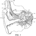
- Figure 1 shows some components of a typical cochlear implant system where an external microphone provides an audio signal input to an external signal processor 111 which implements one of various known signal processing schemes.
- signal processing approaches that are well-known in the field of cochlear implants include continuous interleaved sampling (CIS) digital signal processing, channel specific sampling sequences (CSSS) digital signal processing, spectral peak (SPEAK) digital signal processing, fine structure processing (FSP) and compressed analog (CA) signal processing.
- CIS continuous interleaved sampling
- CSSS channel specific sampling sequences
- SPEAK spectral peak
- FSP fine structure processing
- CA compressed analog
- the processed signal is converted by the external signal processor 111 into a digital data format, such as a sequence of data frames, for transmission by an external coil 107 into a receiving stimulator processor 108 .
- the receiver processor in the stimulator processor 108 may perform additional signal processing such as error correction, pulse formation, etc., and produces a stimulation pattern (based on the extracted audio information) that is sent through electrode lead 109 to an implanted electrode array 110 .
- the electrode array 110 includes multiple stimulation contacts 112 on its surface that provide selective electrical stimulation of the cochlea 104 .
- An audio signal such as speech or music
- One common speech coding strategy is the is the so called “continuous-interleaved-sampling strategy" (CIS), as described by Wilson B. S., Finley C. C., Lawson D. T., Wolford R. D., Eddington D. K., Rabinowitz W. M., "Better speech recognition with cochlear implants," Nature, vol. 352, 236 - 238 (July 1991 ).
- the CIS speech coding strategy samples the signal envelopes at predetermined time intervals, providing a remarkable level of speech understanding merely by coding the signal envelope of the speech signal.
- auditory neurons phase lock to amplitude modulated electrical pulse trains (see, for example, Middlebrooks, J. C., “Auditory Cortex Phase Locking to Amplitude-Modulated Cochlear Implant Pulse Trains," J Neurophysiol , 100(1), p. 76-912008, 2008 July ).
- Older speech coding strategies mainly encode the slowly varying signal envelope information and do not transmit the fine time structure of a signal. More recent coding strategies, for example, Fine Structure Processing (FSP), also transmit the fine time structure information.
- FSP Fine Structure Processing
- the fine time structure of low frequency channels is transmitted through Channel Specific Sampling Sequences (CSSS) that start at negative to positive zero crossings of the respective band pass filter output (see U.S. Patent 6.594.525 ).
- CSSS Channel Specific Sampling Sequences
- the basic idea of FSP is to apply a stimulation pattern, where a particular relationship to the center frequencies of the filter channels is preserved, i.e., the center frequencies are represented in the temporal waveforms of the stimulation patterns, and are not fully removed, as is done in CIS.
- Each stimulation channel is associated with a particular CSSS, which is a sequence of ultra-high-rate biphasic pulses (typically 5-10kpps).
- Each CSSS has a distinct length (number of pulses) and distinct amplitude distribution.
- the length of a CSSS may be derived, for example, from the center frequency of the associated band pass filter.
- a CSSS associated with a lower filter channel is longer than a CSSS associated with a higher filter channel. For example, it may be one half of the period of the center frequency.
- the amplitude distribution may be adjusted to patient specific requirements.
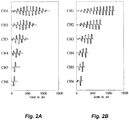
- FIG. 2A-2B show two examples of CSSS for a 6-channel system.
- the CSSS's are derived by sampling one half of a period of a sinusoid whose frequency is equal to the center frequency of the band pass filter (center frequencies at 440 Hz, 696 Hz, 1103 Hz, 1745 Hz, 2762 Hz, and 4372 Hz). Sampling is achieved by means of biphasic pulses at a rate of 10 kpps and a phase duration of 25 ⁇ s.
- the center frequencies i.e., the "sequences" consist of only one pulse, respectively.
- amplitude distributions may be utilized.
- the sequences are derived by sampling one quarter of a sinusoid with a frequency, which is half the center frequency of the band pass filters.
- These CSSS's have about the same durations as the CSSS's in Fig. 2A , respectively, but the amplitude distribution is monotonically increasing. Such monotonic distributions might be advantageous, because each pulse of the sequence can theoretically stimulate neurons at sites which cannot be reached by its predecessors.
- FIG. 3 illustrates a typical signal processing implementation of the FSP coding strategy.
- the audio signal is first split up into spectral bands by means of a filter bank of band pass filters 301 .
- Each of these spectral bands is then further processed by a zero crossing detector 303 that detects the negative to positive zeros crossings of each spectral band.
- the CSSS 305 are inserted at the start of the negative to positive zero crossings of their respective band pass filter output.
- An envelope detector 307 provides the envelopes of band pass time signals, which include unresolved harmonics and are modulated with the difference tones of the harmonics, mainly the fundamental frequency F0.
- the resulting pulses are undesirably amplitude modulated mainly with F0. This also applies to the frequency bands that are designed to transmit fine time structure, in addition to amplitude cues.
- WO 2014/108202 A1 discloses an auditory prosthesis device for neural stimulation of a patient hearing.
- the described prosthesis allows for generating stimulation parameters based on a noise reduced envelope signal in accordance with various stimulation strategies, employing a stimulation strategy module.
- Such stimulation strategy may involve generating stimulation parameters which direct the an intracochlear stimulator to generate and concurrently apply weighted stimulation current via a plurality of stimulation channels S1, ..., Sn in order to effectuate a current steering stimulation energy.
- the stimulation strategy module may be configured to generate stimulation parameters for applying electrical stimulation via only a subset N of the stimulation channels in order to effectuate an N-of-M stimulation strategy.
- the stimulation strategy module always receives signals that have undergone envelope detection.
- the described auditory prosthesis further allows for controlling a filter bank and/or a mapping module in such a manner that respective settings can be chosen depending on whether a "normal" audio signal having no bandwidth limitations or a bandwidth-limited audio signal (typically an audio signal from a telephone) is supplied. If it is determined that the audio signal has a limited bandwidth, one of two different mapping schemes can be applied. In the first mapping scheme, the mapping between various analysis channels F1, F2, ... and stimulation channels S1, S2, ... is not changed, but the center frequencies of the analysis channels F1, F2, ... are reduced. In a second variant, the filter bank setting remains unchanged with regard to the standard operation mode, but the mapping between the analysis channels F1, F2, ...
- the present invention is directed to a system as defined in claim 1 and a method as defined in claim 9 for signal processing in a hearing implant system that has an implanted electrode array with multiple stimulation contacts for delivering electrode stimulation signals to adjacent auditory neural tissue.
- Preferred embodiments are defined by the dependent claims. Aspects, embodiments or examples of the present disclosure which do not fall within the scope of the appended claims are not part of the present invention.
- a band pass filter bank is configured for processing an audio input signal to generate multiple band pass signals which represent associated bands of audio frequencies in the audio input signal.
- An implant signal processor is configured for processing the band pass signals to generate the electrode stimulation signals. This processing includes: i. monitoring a key feature characteristic of the audio input signal, ii. using an original coding strategy to generate the electrode stimulation signals when the key feature is less than or equal to an initial value, and iii. using a different new coding strategy to generate the electrode stimulation signals when the key feature is greater than or equal to a coding change value.
- the implant signal processor is configured for automatically transitioning from the original coding strategy to the new coding strategy over a transition period of time during which the implant signal processor adaptively changes the original coding strategy to become the new coding strategy.
- one of the coding strategies may use adaptive stimulation pulse rates while the other coding strategy uses constant stimulation rates.
- the implant signal processor may be configured to use an adaptive stimulation pulse rate based on channel specific sampling sequences (CSSS), and adaptively increases the CSSS pulse sequence length to transition to a constant stimulation rate coding strategy.
- the implant signal processor may be configured to use time intervals during which no pulse is applied to transition to a constant stimulation rate coding strategy.
- CSSS channel specific sampling sequences
- the implant signal processor may specifically be configured for automatically transitioning either while the key feature changes from the initial value to the coding change value, or after.
- the key feature may be a signal to noise ratio (SNR) of the audio input signal or a direct to reverberation ratio (DRR) of the audio input signal.
- SNR signal to noise ratio
- DRR direct to reverberation ratio
- Parameters of a given cochlear implant signal coding strategy might not be optimal for all listening conditions. For example, in noisy conditions some coding strategies might perform better than others since temporal fine structure typically is more affected by noise than is the band pass signal envelope. It would be beneficial to switch from one coding strategy to another, depending on listening conditions. The switching could be performed in small increments so that the transition happens in a smooth morphing from one coding strategy to the other.
- the audio input signal is monitored and analyzed to estimate one or more key features that are present. Based on the key feature(s), the signal coding strategy is automatically modified.
- the signal to noise ratio (SNR) of the audio input signal can be estimated. It is assumed that event-based coding strategies that transmit temporal fine structure of the input signal (such as FSP by MED-EL) are optimal in relatively quiet listening conditions, while envelope-based coding strategies (such as HD-CIS by MED-EL are better in noisier conditions. A smooth transition can then be made automatically from FSP to HD-CIS based on the SNR of the audio input signal by modifying the length and the shape of the channel-specific sampling sequences (CSSS) that are used for the output stimulation pulses.
- CSSS channel-specific sampling sequences
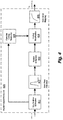
- FIG. 4 shows various functional blocks in a generic coding modification signal processing arrangement for a hearing implant system that has an implanted electrode array with multiple stimulation contacts for delivering electrode stimulation signals to adjacent auditory neural tissue.
- the implant signal processor 400 uses an FSP approach and includes a key feature estimation module 401 that monitors one or more key features in an audio input signal that reflects the current hearing environment.
- a conventional band pass filter bank 402 processes the audio input signal to generate multiple band pass signals which each represent associated bands of audio frequencies in the audio input signal.
- a feature extraction module 403 processes the band pass signals from the band pass filter bank 402 to extract the band pass envelopes and fine structure time information and generate an initial set of stimulation pulses for the stimulation contacts according to an original coding strategy.
- the original coding strategy may be an event-based coding strategy such as FSP that uses adaptive stimulation rates according to the fine structure information in the band pass signals.
- a coding parameter module 405 monitors the key feature from the key feature estimation module 401 and so long as value of the key feature is less than or equal to some given initial value, the coding modification block 404 passes along the stimulation pulses as produced by the feature extraction module 403 according to the original coding strategy. At some point when the key feature is greater than or equal to a coding change value, the coding parameter module 405 controls the coding modification block 404 to begin adjusting the stimulation pulses to adaptively change the original coding strategy over a transition period of time to automatically transition to the new coding strategy.
- the new coding strategy may be an envelope-based coding strategy such as CIS or HD-CIS that uses stimulation pulses at a constant stimulation rate.
- the implant signal processor 400 may specifically be configured for automatically transitioning either while the key feature changes from the initial value to the coding change value, or after.
- a non-linear mapping module 406 then adjusts the amplitude of the output stimulation pulses using anon-linear mapping that provides patient-specific scaling and data stream generation.
- FIG. 5 shows various functional blocks in an embodiment of the present invention where the implant signal processor 500 uses SNR as the key feature with CSSS pulse sequences.
- An SNR estimation module 501 that monitors one or more key features in the input signal, while a band pass filter bank 502 processes the audio input signal to generate the band pass signals.
- a zero crossing detector 506 detects the negative to positive zeros crossings of each band pass signal (the temporal fine structure information).
- a channel specific sequence module 507 creates CSSS output timing request pulses at the start of the negative to positive zero crossings of each band pass signal, while a feature extraction module 503 derives the band pass signal envelopes.
- the pulse weighting module 504 weights (amplitude modulates) the CSSS stimulation pulses with the band pass envelopes, which is then further adjusted by the non-linear mapping module 505 that provides patient-specific scaling and data stream generation.
- the channel specific sequence module 507 determines an event-specific length for the CSSS pulse sequence ("FL interval").
- the pulse weighting module 504 shapes the CSSS pulse sequence to follow the band pass envelope amplitude so that the band pass envelope is sampled with the CSSS sequence.
- the channel specific sequence module 507 adjusts the FL interval to be so short that a CSSS pulse sequence may consist of as little as a single pulse.
- the channel specific sequence module 507 increases the FL interval and adds more pulses to the CSSS sequence until at some point for a low SNR (high noise), the last pulse of the CSSS sequence is seamlessly followed by the first pulse of the next CSSS sequence, resulting in a continuous (constant rate) sampling of the band pass envelopes from the feature extraction module 503 . If the length of the FL interval becomes larger than the time between two consecutive trigger events (i.e., two zero crossings), the channel specific sequence module 507 may terminate the existing CSSS sequence when the next trigger event occurs and the FL interval of the following trigger event overrules the previous FL interval.
- the channel specific sequence module 507 may continue with the CSSS pulse sequence initiated by the first trigger event and ignore the subsequent trigger event so that the end of the existing FL interval, a new FL interval is determined. Once the SNR signal from the SNR estimation module 501 increases again, the channel specific sequence module 507 adaptively adjusts the FS interval to again become shorter than the times between the trigger events.
- the band pass signal is the higher frequency full sine wave signal in dark gray
- the Hilbert band pass envelope is the slower varying half sine wave trace shown in light gray
- the vertical black lines represent the applied CSSS sequences with a sequence length of one.
- Figure 7 shows the same signal as in Fig. 6 , when the SNR signal decreases down to 5 dB (more noise) and the FL interval is increased so that the CSSS sequences contain three pulses each.
- a subsequent time interval-FS-interval- may be determined within which a pulse has to be applied.
- the length of this FS-interval may be determined by the value of the SNR signal at the time when the pulse has been applied: If the SNR is high, the FS-interval may be chosen to be long, while if the SNR is low, the FS-interval may be chosen to be short.
- a shortest possible FS-interval can be defined that corresponds to the maximum stimulation rate.
- Figure 9 shows an example of a processed band pass signal and SNR-adapted pulse time intervals according to an embodiment of the present invention.
- E1-E5 vertical solid lines
- the SNR is decreasing over time t (i.e. from left to right)
- the refractory period is as shown by the corresponding horizontal arrows across the bottom the figure denoted as "refractory time”.
- the first CSSS pulse is, without limitation, applied at the zero crossing event E1. Since the SNR is high, the corresponding FS-interval I_1 is relatively long.
- next zero crossing event E2 occurs before the end of the I_1 FS-interval, so the next CSSS pulse is applied at E2, and the same situation with I_2 and E3 although the SNR has meantime decreased so that I_2 is shorter than I_1.
- a CSSS pulse is forced because no further zero crossing has occurred within this FS-interval starting after zero crossing event E3 (also the refractory time (after E3) is still shorter than 1_3).
- E3 also the refractory time (after E3) is still shorter than 1_3).
- the next zero crossing event occurs at E4, but that is still within the refractory period after the last applied pulse at E3' so there is no pulse applied at E4 nor is any corresponding FS-interval determined.
- the maximum stimulation rate can be set to be proportional to the inverse of the minimum possible interval (e.g. the refractory period) so that the instantaneous stimulation rate (which equals 1/FS-interval) cannot exceed a given defined value; e.g. a typical rate as presently used for CIS or HD-CIS coding strategies.
- an envelope-based coding strategy such as CIS or HD-CIS (constant sampling of each channel in a prescribed manner with the defined maximum stimulation rate).
- the MCL and THR values may vary when switching from one specific coding strategy to another, so the MCL and THR values of the patient-specific scaling function should also be adjusted (in addition to the CSSS sequence) to promote a loudness-balanced transition between the different coding strategies.
- the modification of the CSSS sequences can also be done channel-wise, i.e. based on channel-specific SNR values. And while the foregoing was described with SNR being the parameter for subsequent adaptive modifications, other specific signal parameters that characterize the quality of an existing hearing situation may be used as well; e.g. the direct to reverberation ratio (DRR).
- DRR direct to reverberation ratio
- Embodiments of the present invention adapt the sound coding strategy to changes in the sound environment with optimal settings for each environment. With SNR-adjusted sampling, temporal fine structure is provided in situations where it is not disturbed, while the sound coding is morphed seamlessly to a more noise-robust envelope coding for better sound perception in noisier environments.
- Embodiments of the invention may be implemented in part in any conventional computer programming language such as VHDL, SystemC, Verilog, ASM, etc.
- Alternative embodiments of the invention may be implemented as pre-programmed hardware elements, other related components, or as a combination of hardware and software components.
- Embodiments can be implemented in part as a computer program product for use with a computer system.
- Such implementation may include a series of computer instructions fixed either on a tangible medium, such as a computer readable medium (e.g., a diskette, CD-ROM, ROM, or fixed disk) or transmittable to a computer system, via a modem or other interface device, such as a communications adapter connected to a network over a medium.
- the medium may be either a tangible medium (e.g., optical or analog communications lines) or a medium implemented with wireless techniques (e.g., microwave, infrared or other transmission techniques).
- the series of computer instructions embodies all or part of the functionality previously described herein with respect to the system.
- Such computer instructions can be written in a number of programming languages for use with many computer architectures or operating systems. Furthermore, such instructions may be stored in any memory device, such as semiconductor, magnetic, optical or other memory devices, and may be transmitted using any communications technology, such as optical, infrared, microwave, or other transmission technologies. It is expected that such a computer program product may be distributed as a removable medium with accompanying printed or electronic documentation (e.g., shrink wrapped software), preloaded with a computer system (e.g., on system ROM or fixed disk), or distributed from a server or electronic bulletin board over the network (e.g., the Internet or World Wide Web).
- printed or electronic documentation e.g., shrink wrapped software
- preloaded with a computer system e.g., on system ROM or fixed disk
- server or electronic bulletin board e.g., the Internet or World Wide Web
Landscapes
- Health & Medical Sciences (AREA)
- Otolaryngology (AREA)
- Life Sciences & Earth Sciences (AREA)
- Biomedical Technology (AREA)
- Nuclear Medicine, Radiotherapy & Molecular Imaging (AREA)
- Radiology & Medical Imaging (AREA)
- Engineering & Computer Science (AREA)
- Animal Behavior & Ethology (AREA)
- General Health & Medical Sciences (AREA)
- Public Health (AREA)
- Veterinary Medicine (AREA)
- Electrotherapy Devices (AREA)
- Prostheses (AREA)
- Cardiology (AREA)
- Heart & Thoracic Surgery (AREA)
Description
- The present invention relates to signal processing arrangements for hearing implants, and more particularly, to automatically transitioning speech coding strategies for cochlear implants.
- As shown in
Figure 1 , sounds are transmitted by a human ear from theouter ear 101 to the tympanic membrane (eardrum) 102, which moves the bones of the middle ear 103 (malleus, incus, and stapes) that vibrate the oval window and round window openings of thecochlea 104. Thecochlea 104 is a long fluid-filled duct wound spirally about its axis for approximately two and a half turns. It includes an upper channel known as the scala vestibuli and a lower channel known as the scala tympani, which are connected by the cochlear duct. Thecochlea 104 forms an upright spiraling cone with a center called the modiolus where the spiral ganglion cells of theacoustic nerve 113 reside. In response to received sounds transmitted by themiddle ear 103, thecochlea 104 functions as a transducer to generate electric pulses which are transmitted to thecochlear nerve 113, and ultimately to the brain which perceives the neural signals as sound. - Hearing is impaired when there are problems in the ability to transduce external sounds into meaningful action potentials along the neural substrate of the
cochlea 104. To improve impaired hearing, auditory prostheses have been developed. In some cases, hearing impairment can be addressed by a cochlear implant (CI), a brainstem-, midbrain- or cortical implant that electrically stimulates auditory nerve tissue with small currents delivered by multiple electrode contacts distributed along an implant electrode. For cochlear implants, the electrode array is inserted into thecochlea 104. For brain-stem, midbrain and cortical implants, the electrode array is located in the auditory brainstem, midbrain or cortex, respectively. -
Figure 1 shows some components of a typical cochlear implant system where an external microphone provides an audio signal input to anexternal signal processor 111 which implements one of various known signal processing schemes. For example, signal processing approaches that are well-known in the field of cochlear implants include continuous interleaved sampling (CIS) digital signal processing, channel specific sampling sequences (CSSS) digital signal processing, spectral peak (SPEAK) digital signal processing, fine structure processing (FSP) and compressed analog (CA) signal processing. - The processed signal is converted by the
external signal processor 111 into a digital data format, such as a sequence of data frames, for transmission by anexternal coil 107 into areceiving stimulator processor 108. Besides extracting the audio information, the receiver processor in thestimulator processor 108 may perform additional signal processing such as error correction, pulse formation, etc., and produces a stimulation pattern (based on the extracted audio information) that is sent throughelectrode lead 109 to an implantedelectrode array 110. Typically, theelectrode array 110 includesmultiple stimulation contacts 112 on its surface that provide selective electrical stimulation of thecochlea 104. - An audio signal, such as speech or music, can be processed into multiple frequency band pass signals, each having a signal envelope and fine time structure within the envelope. One common speech coding strategy is the is the so called "continuous-interleaved-sampling strategy" (CIS), as described by Wilson B. S., Finley C. C., Lawson D. T., Wolford R. D., Eddington D. K., Rabinowitz W. M., "Better speech recognition with cochlear implants," Nature, vol. 352, 236 - 238 (July 1991). The CIS speech coding strategy samples the signal envelopes at predetermined time intervals, providing a remarkable level of speech understanding merely by coding the signal envelope of the speech signal. This can be explained, in part, by the fact that auditory neurons phase lock to amplitude modulated electrical pulse trains (see, for example, Middlebrooks, J. C., "Auditory Cortex Phase Locking to Amplitude-Modulated Cochlear Implant Pulse Trains," J Neurophysiol , 100(1), p. 76-912008, 2008 July).
- However, both signal cues, the envelope and the final time structure, are important for normal hearing subjects (see, for example, Zeng F., Nie K., Stickney G., Kong Y., "Auditory Perception with Slowly-Varying Amplitude and Frequency Modulations," In: D. Pressnitzer, A. de Cheveign'e, S. McAdams, and L. Collet, "Auditory Signal Processing: Physiology, Psychoacoustics, and Models, Springer Verlag, New York, pp. 237-243, 2004).
- Older speech coding strategies mainly encode the slowly varying signal envelope information and do not transmit the fine time structure of a signal. More recent coding strategies, for example, Fine Structure Processing (FSP), also transmit the fine time structure information. In FSP, the fine time structure of low frequency channels is transmitted through Channel Specific Sampling Sequences (CSSS) that start at negative to positive zero crossings of the respective band pass filter output (see
U.S. Patent 6.594.525 ). The basic idea of FSP is to apply a stimulation pattern, where a particular relationship to the center frequencies of the filter channels is preserved, i.e., the center frequencies are represented in the temporal waveforms of the stimulation patterns, and are not fully removed, as is done in CIS. Each stimulation channel is associated with a particular CSSS, which is a sequence of ultra-high-rate biphasic pulses (typically 5-10kpps). Each CSSS has a distinct length (number of pulses) and distinct amplitude distribution. The length of a CSSS may be derived, for example, from the center frequency of the associated band pass filter. A CSSS associated with a lower filter channel is longer than a CSSS associated with a higher filter channel. For example, it may be one half of the period of the center frequency. The amplitude distribution may be adjusted to patient specific requirements. - For illustration,
Figure 2A-2B show two examples of CSSS for a 6-channel system. InFig. 2A , the CSSS's are derived by sampling one half of a period of a sinusoid whose frequency is equal to the center frequency of the band pass filter (center frequencies at 440 Hz, 696 Hz, 1103 Hz, 1745 Hz, 2762 Hz, and 4372 Hz). Sampling is achieved by means of biphasic pulses at a rate of 10 kpps and a phase duration of 25 µs. For Channels 5 and 6, one half of a period of the center frequencies is too short to give space for more than one stimulation pulse, i.e., the "sequences" consist of only one pulse, respectively. Other amplitude distributions may be utilized. For example, inFig. 2B , the sequences are derived by sampling one quarter of a sinusoid with a frequency, which is half the center frequency of the band pass filters. These CSSS's have about the same durations as the CSSS's inFig. 2A , respectively, but the amplitude distribution is monotonically increasing. Such monotonic distributions might be advantageous, because each pulse of the sequence can theoretically stimulate neurons at sites which cannot be reached by its predecessors. -
Figure 3 illustrates a typical signal processing implementation of the FSP coding strategy. The audio signal is first split up into spectral bands by means of a filter bank ofband pass filters 301. Each of these spectral bands is then further processed by a zerocrossing detector 303 that detects the negative to positive zeros crossings of each spectral band. The CSSS 305 are inserted at the start of the negative to positive zero crossings of their respective band pass filter output. Anenvelope detector 307 provides the envelopes of band pass time signals, which include unresolved harmonics and are modulated with the difference tones of the harmonics, mainly the fundamental frequency F0. When the CSSS stimulation pulses are weighted 309 with these envelopes, the resulting pulses are undesirably amplitude modulated mainly with F0. This also applies to the frequency bands that are designed to transmit fine time structure, in addition to amplitude cues. -
WO 2014/108202 A1 discloses an auditory prosthesis device for neural stimulation of a patient hearing. The described prosthesis allows for generating stimulation parameters based on a noise reduced envelope signal in accordance with various stimulation strategies, employing a stimulation strategy module. Such stimulation strategy may involve generating stimulation parameters which direct the an intracochlear stimulator to generate and concurrently apply weighted stimulation current via a plurality of stimulation channels S1, ..., Sn in order to effectuate a current steering stimulation energy. Additionally or alternatively, the stimulation strategy module may be configured to generate stimulation parameters for applying electrical stimulation via only a subset N of the stimulation channels in order to effectuate an N-of-M stimulation strategy. Herein, the stimulation strategy module always receives signals that have undergone envelope detection. In addition, and unrelated to the stimulation strategy applied by the stimulation strategy module, the described auditory prosthesis further allows for controlling a filter bank and/or a mapping module in such a manner that respective settings can be chosen depending on whether a "normal" audio signal having no bandwidth limitations or a bandwidth-limited audio signal (typically an audio signal from a telephone) is supplied. If it is determined that the audio signal has a limited bandwidth, one of two different mapping schemes can be applied. In the first mapping scheme, the mapping between various analysis channels F1, F2, ... and stimulation channels S1, S2, ... is not changed, but the center frequencies of the analysis channels F1, F2, ... are reduced. In a second variant, the filter bank setting remains unchanged with regard to the standard operation mode, but the mapping between the analysis channels F1, F2, ... and the stimulation channels S1, S2, ... is changed in such a way that at least one of the analysis channels is mapped to a stimulation channel corresponding to higher frequency stimulation than the stimulation channel it is mapped to in the standard mapping configuration.
In WOUTERS JAN ET AL: "Sound Coding in Cochlear Implants: From electric pulses to hearing", IEEE SIGNAL PROCESSING MAGAZINE, IEEE SERVICE CENTER, PISCATAWAY, NJ, US,vol. 32, no. 2, 1 March 2015 (2015-03-01), pages 67-80, various cochlear implant stimulation strategies, which convert sound signals into patterns of nerve stimulation, are described, and the neurophysiological rationale behind some of the strategies is discussed. - The present invention is directed to a system as defined in claim 1 and a method as defined in claim 9 for signal processing in a hearing implant system that has an implanted electrode array with multiple stimulation contacts for delivering electrode stimulation signals to adjacent auditory neural tissue. Preferred embodiments are defined by the dependent claims. Aspects, embodiments or examples of the present disclosure which do not fall within the scope of the appended claims are not part of the present invention.
- A band pass filter bank is configured for processing an audio input signal to generate multiple band pass signals which represent associated bands of audio frequencies in the audio input signal. An implant signal processor is configured for processing the band pass signals to generate the electrode stimulation signals. This processing includes: i. monitoring a key feature characteristic of the audio input signal, ii. using an original coding strategy to generate the electrode stimulation signals when the key feature is less than or equal to an initial value, and iii. using a different new coding strategy to generate the electrode stimulation signals when the key feature is greater than or equal to a coding change value. The implant signal processor is configured for automatically transitioning from the original coding strategy to the new coding strategy over a transition period of time during which the implant signal processor adaptively changes the original coding strategy to become the new coding strategy.
- In addition or alternatively, one of the coding strategies may use adaptive stimulation pulse rates while the other coding strategy uses constant stimulation rates. For example, the implant signal processor may be configured to use an adaptive stimulation pulse rate based on channel specific sampling sequences (CSSS), and adaptively increases the CSSS pulse sequence length to transition to a constant stimulation rate coding strategy. Or, the implant signal processor may be configured to use time intervals during which no pulse is applied to transition to a constant stimulation rate coding strategy.
- The implant signal processor may specifically be configured for automatically transitioning either while the key feature changes from the initial value to the coding change value, or after. And the key feature may be a signal to noise ratio (SNR) of the audio input signal or a direct to reverberation ratio (DRR) of the audio input signal.
-
-
Figure 1 shows anatomical structures of a human ear and some components of a typical cochlear implant system. -
Figure 2 shows channel specific sampling sequences (CSSS) for two 6-channel systems utilizing biphasic pulses at 10 kpp/s and phase duration of 25 µs:- A. derived from a sinusoid within [0 - π]
- B. derived from a sinusoid within [0 - π /2], amplitudes monotonically increasing.
-
Figure 3 shows various functional blocks in a prior art fine structure processing (FSP) signal processing arrangement. -
Figure 4 shows various functional blocks in a coding modification signal processing arrangement according to an embodiment of the present invention. -
Figure 5 shows various functional blocks in a specific embodiment of the present invention using SNR as the key feature with CSSS. -
Figure 6 shows an example of a processed band pass signal and the resulting CSSS pulse sequence for a vowel with added Gaussian noise and a SNR = 10 dB. -
Figure 7 shows the same signal as inFig. 6 , with SNR = 5 dB. -
Figure 8 shows the same signal as inFig. 6 , with SNR = 0 dB. -
Figure 9 shows an example of a processed band pass signal and SNR-adapted pulse time intervals according to an embodiment of the present invention. - Parameters of a given cochlear implant signal coding strategy might not be optimal for all listening conditions. For example, in noisy conditions some coding strategies might perform better than others since temporal fine structure typically is more affected by noise than is the band pass signal envelope. It would be beneficial to switch from one coding strategy to another, depending on listening conditions. The switching could be performed in small increments so that the transition happens in a smooth morphing from one coding strategy to the other. The audio input signal is monitored and analyzed to estimate one or more key features that are present. Based on the key feature(s), the signal coding strategy is automatically modified.
- As an example of a key feature, the signal to noise ratio (SNR) of the audio input signal can be estimated. It is assumed that event-based coding strategies that transmit temporal fine structure of the input signal (such as FSP by MED-EL) are optimal in relatively quiet listening conditions, while envelope-based coding strategies (such as HD-CIS by MED-EL are better in noisier conditions. A smooth transition can then be made automatically from FSP to HD-CIS based on the SNR of the audio input signal by modifying the length and the shape of the channel-specific sampling sequences (CSSS) that are used for the output stimulation pulses.
-
Figure 4 shows various functional blocks in a generic coding modification signal processing arrangement for a hearing implant system that has an implanted electrode array with multiple stimulation contacts for delivering electrode stimulation signals to adjacent auditory neural tissue. The implant signal processor 400 uses an FSP approach and includes a key feature estimation module 401 that monitors one or more key features in an audio input signal that reflects the current hearing environment. A conventional band pass filter bank 402 processes the audio input signal to generate multiple band pass signals which each represent associated bands of audio frequencies in the audio input signal. - A feature extraction module 403 processes the band pass signals from the band pass filter bank 402 to extract the band pass envelopes and fine structure time information and generate an initial set of stimulation pulses for the stimulation contacts according to an original coding strategy. For example, the original coding strategy may be an event-based coding strategy such as FSP that uses adaptive stimulation rates according to the fine structure information in the band pass signals.
- A coding parameter module 405 monitors the key feature from the key feature estimation module 401 and so long as value of the key feature is less than or equal to some given initial value, the coding modification block 404 passes along the stimulation pulses as produced by the feature extraction module 403 according to the original coding strategy. At some point when the key feature is greater than or equal to a coding change value, the coding parameter module 405 controls the coding modification block 404 to begin adjusting the stimulation pulses to adaptively change the original coding strategy over a transition period of time to automatically transition to the new coding strategy. For example, the new coding strategy may be an envelope-based coding strategy such as CIS or HD-CIS that uses stimulation pulses at a constant stimulation rate. The implant signal processor 400 may specifically be configured for automatically transitioning either while the key feature changes from the initial value to the coding change value, or after. A non-linear mapping module 406 then adjusts the amplitude of the output stimulation pulses using anon-linear mapping that provides patient-specific scaling and data stream generation.
-
Figure 5 shows various functional blocks in an embodiment of the present invention where theimplant signal processor 500 uses SNR as the key feature with CSSS pulse sequences. AnSNR estimation module 501 that monitors one or more key features in the input signal, while a bandpass filter bank 502 processes the audio input signal to generate the band pass signals. A zerocrossing detector 506 detects the negative to positive zeros crossings of each band pass signal (the temporal fine structure information). A channelspecific sequence module 507 creates CSSS output timing request pulses at the start of the negative to positive zero crossings of each band pass signal, while afeature extraction module 503 derives the band pass signal envelopes. Thepulse weighting module 504 weights (amplitude modulates) the CSSS stimulation pulses with the band pass envelopes, which is then further adjusted by thenon-linear mapping module 505 that provides patient-specific scaling and data stream generation. - At each zero crossing trigger event from the zero
crossing detector 506, the channelspecific sequence module 507 determines an event-specific length for the CSSS pulse sequence ("FL interval"). Thepulse weighting module 504 shapes the CSSS pulse sequence to follow the band pass envelope amplitude so that the band pass envelope is sampled with the CSSS sequence. When the SNR signal from theSNR estimation module 501 is relatively high (quiet sound environment), the channelspecific sequence module 507 adjusts the FL interval to be so short that a CSSS pulse sequence may consist of as little as a single pulse. As the SNR signal from theSNR estimation module 501 decreases (the environment becomes noisier), the channelspecific sequence module 507 increases the FL interval and adds more pulses to the CSSS sequence until at some point for a low SNR (high noise), the last pulse of the CSSS sequence is seamlessly followed by the first pulse of the next CSSS sequence, resulting in a continuous (constant rate) sampling of the band pass envelopes from thefeature extraction module 503. If the length of the FL interval becomes larger than the time between two consecutive trigger events (i.e., two zero crossings), the channelspecific sequence module 507 may terminate the existing CSSS sequence when the next trigger event occurs and the FL interval of the following trigger event overrules the previous FL interval. Or the channelspecific sequence module 507 may continue with the CSSS pulse sequence initiated by the first trigger event and ignore the subsequent trigger event so that the end of the existing FL interval, a new FL interval is determined. Once the SNR signal from theSNR estimation module 501 increases again, the channelspecific sequence module 507 adaptively adjusts the FS interval to again become shorter than the times between the trigger events. -
Figure 6 shows an example of a processed band pass signal and the resulting CSSS pulse sequence for a vowel with added Gaussian noise and a SNR = 10 dB. The band pass signal is the higher frequency full sine wave signal in dark gray, the Hilbert band pass envelope is the slower varying half sine wave trace shown in light gray, and the vertical black lines represent the applied CSSS sequences with a sequence length of one.Figure 7 shows the same signal as inFig. 6 , when the SNR signal decreases down to 5 dB (more noise) and the FL interval is increased so that the CSSS sequences contain three pulses each.Figure 8 shows the same signal as inFig. 6 , with SNR = 0 dB (noisier still) where the FL interval is so long that the CSSS sequence performs a continuous sampling of the band pass envelope that is similar to the HD-CIS coding strategy. - In addition to or alternatively to adaptively varying the length of the CSSS interval, other specific embodiments may adaptively control other signal variables. For example, in combination with the application of a CSSS pulse at a specific event (e.g. a zero crossing event), a subsequent time interval-FS-interval-may be determined within which a pulse has to be applied. The length of this FS-interval may be determined by the value of the SNR signal at the time when the pulse has been applied: If the SNR is high, the FS-interval may be chosen to be long, while if the SNR is low, the FS-interval may be chosen to be short. To restrict the stimulation rate to a maximum value that reflects the refractory period of the auditory nerve fibers, a shortest possible FS-interval can be defined that corresponds to the maximum stimulation rate. There are several different specific possibilities:
- If another timing event occurs within the FS-interval determined from the previous timing event, and the time between the two timing events is greater than the refractory period, then a pulse can be applied at the second timing event and a new FS-interval is initiated that overrules the previous one.
- If another timing event occurs within the FS-interval determined from the previous timing event, but the time between the two timing events is shorter than the refractory period, then a pulse can be applied at the end of the refractory period and a new FS-interval is initiated that overrules the previous one.
- If no additional timing event appears before the end of the current FS-interval and the refractory period is shorter than the FS-interval, then another pulse can be applied (forced) at the end of the FS-interval .
- If no additional timing event appears before the end of the current FS-interval interval, but the refractory period is greater than the FS-interval, then another pulse can be applied (forced) at the end of the refractory period.
-
Figure 9 shows an example of a processed band pass signal and SNR-adapted pulse time intervals according to an embodiment of the present invention. InFigure 9 , it is assumed that five zero crossing timing events E1-E5 (vertical solid lines) are detected, the SNR is decreasing over time t (i.e. from left to right), and the refractory period is as shown by the corresponding horizontal arrows across the bottom the figure denoted as "refractory time". The first CSSS pulse is, without limitation, applied at the zero crossing event E1. Since the SNR is high, the corresponding FS-interval I_1 is relatively long. The next zero crossing event E2 occurs before the end of the I_1 FS-interval, so the next CSSS pulse is applied at E2, and the same situation with I_2 and E3 although the SNR has meantime decreased so that I_2 is shorter than I_1. However, at the event E3' that occurs at the end of the I_3 FS-interval, a CSSS pulse is forced because no further zero crossing has occurred within this FS-interval starting after zero crossing event E3 (also the refractory time (after E3) is still shorter than 1_3). The next zero crossing event occurs at E4, but that is still within the refractory period after the last applied pulse at E3' so there is no pulse applied at E4 nor is any corresponding FS-interval determined. Similarly, at E5 no pulse is applied, and in addition, at E4' the SNR is so low that the corresponding I_5 FS-interval is determined to be shorter than the refractory period so at E5', no pulse is applied but instead is delayed until E5" corresponding to the end of the refractory period after event E4'. - When the SNR later increases more and more (not shown in
Fig. 9 ) the FS-intervals will again become longer and longer until a zero crossing event will be detected after the end of the refractory time but before the end of an FS-interval. From that point on, the zero crossing events will again determine the pulse sequence and the coding strategy follows the known event-based coding strategies until the SNR decreases again. The maximum stimulation rate can be set to be proportional to the inverse of the minimum possible interval (e.g. the refractory period) so that the instantaneous stimulation rate (which equals 1/FS-interval) cannot exceed a given defined value; e.g. a typical rate as presently used for CIS or HD-CIS coding strategies. In general, the lower the SNR, the more the resulting sound coding sequence will be according to an envelope-based coding strategy such as CIS or HD-CIS (constant sampling of each channel in a prescribed manner with the defined maximum stimulation rate). The higher the SNR, the more the resulting sound coding sequence will be like according to a pure event-based coding strategy such as FSP. - The MCL and THR values may vary when switching from one specific coding strategy to another, so the MCL and THR values of the patient-specific scaling function should also be adjusted (in addition to the CSSS sequence) to promote a loudness-balanced transition between the different coding strategies.
- The modification of the CSSS sequences can also be done channel-wise, i.e. based on channel-specific SNR values. And while the foregoing was described with SNR being the parameter for subsequent adaptive modifications, other specific signal parameters that characterize the quality of an existing hearing situation may be used as well; e.g. the direct to reverberation ratio (DRR).
- Both approaches-variation of CSSS lengths and determination of time intervals within which no pulse is applied-yield similar overall results: a smooth transition between event-based (variable rate) and envelope-based (constant rate) coding strategies. Embodiments of the present invention adapt the sound coding strategy to changes in the sound environment with optimal settings for each environment. With SNR-adjusted sampling, temporal fine structure is provided in situations where it is not disturbed, while the sound coding is morphed seamlessly to a more noise-robust envelope coding for better sound perception in noisier environments.
- Embodiments of the invention may be implemented in part in any conventional computer programming language such as VHDL, SystemC, Verilog, ASM, etc. Alternative embodiments of the invention may be implemented as pre-programmed hardware elements, other related components, or as a combination of hardware and software components.
- Embodiments can be implemented in part as a computer program product for use with a computer system. Such implementation may include a series of computer instructions fixed either on a tangible medium, such as a computer readable medium (e.g., a diskette, CD-ROM, ROM, or fixed disk) or transmittable to a computer system, via a modem or other interface device, such as a communications adapter connected to a network over a medium. The medium may be either a tangible medium (e.g., optical or analog communications lines) or a medium implemented with wireless techniques (e.g., microwave, infrared or other transmission techniques). The series of computer instructions embodies all or part of the functionality previously described herein with respect to the system. Those skilled in the art should appreciate that such computer instructions can be written in a number of programming languages for use with many computer architectures or operating systems. Furthermore, such instructions may be stored in any memory device, such as semiconductor, magnetic, optical or other memory devices, and may be transmitted using any communications technology, such as optical, infrared, microwave, or other transmission technologies. It is expected that such a computer program product may be distributed as a removable medium with accompanying printed or electronic documentation (e.g., shrink wrapped software), preloaded with a computer system (e.g., on system ROM or fixed disk), or distributed from a server or electronic bulletin board over the network (e.g., the Internet or World Wide Web). Of course, some embodiments of the invention may be implemented as a combination of both software (e.g., a computer program product) and hardware. Still other embodiments of the invention are implemented as entirely hardware, or entirely software (e.g., a computer program product).
- Although various exemplary embodiments of the invention have been disclosed, it should be apparent to those skilled in the art that various changes and modifications can be made which will achieve some of the advantages of the invention without departing from the scope of the invention which is defined by the appended claims.
Claims (13)
- A signal processing system for a hearing implant system having an implanted electrode array (110) with a plurality of stimulation contacts for delivering electrode stimulation signals to adjacent auditory neural tissue, the system comprising:a band pass filter bank (402, 502) configured for processing an audio input signal to generate a plurality of band pass signals each representing an associated band of audio frequencies in the audio input signal; andan implant signal processor (400, 500) configured for processing the band pass signals to generate the electrode stimulation signals, wherein the processing includes:i. monitoring a key feature characteristic of the audio input signal,ii. using an original coding strategy to generate the electrode stimulation signals when the key feature is less than or equal to an initial value, andiii. using a different new coding strategy to generate the electrode stimulation signals when the key feature is greater than or equal to a coding change value;characterized in that the implant signal processor (400, 500) is configured for automatically transitioning from the original coding strategy to the new coding strategy over a transition period of time during which the implant signal processor adaptively changes the original coding strategy to become the new coding strategy,
wherein one of the coding strategies is an event-based coding strategy and the other coding strategy is an envelope-based coding strategy. - The signal processing system according to claim 1, wherein one of the coding strategies uses adaptive stimulation pulse rates and the other coding strategy uses constant stimulation rates.
- The signal processing system according to claim 2, wherein the implant signal processor (400, 500) is configured to use an adaptive stimulation pulse rate based on channel specific sampling sequences (CSSS) (305), and wherein the implant signal processor is configured to adaptively increase CSSS pulse sequence length to transition to a constant stimulation rate coding strategy.
- The signal processing system according to claim 2, wherein the implant signal processor (400, 500) is configured to transition to a constant stimulation rate coding strategy using time intervals during which no pulse is applied.
- The signal processing system according to claim 1, wherein the implant signal processor (400, 500) is configured for automatically transitioning after the key feature changes from the initial value to the coding change value.
- The signal processing system according to claim 1, wherein the implant signal processor (400, 500) is configured for automatically transitioning while the key feature changes from the initial value to the coding change value.
- The signal processing system according to claim 1, wherein the key feature is a signal to noise ratio (SNR) of the audio input signal.
- The signal processing system according to claim 1, wherein the key feature is a direct to reverberation ratio (DRR) of the audio input signal.
- A method of signal processing for a hearing implant system having an implanted electrode array (110) with a plurality of stimulation contacts for delivering electrode stimulation signals to adjacent auditory neural tissue, the method comprising:processing an audio input signal with a band pass filter bank (402, 502) to generate a plurality of band pass signals each representing an associated band of audio frequencies in the audio input signal; andprocessing the band pass signals to generate the electrode stimulation signals, wherein the processing includes:i. monitoring a key feature characteristic of the audio input signal,ii. using an original coding strategy to generate the electrode stimulation signals when the key feature is less than or equal to an initial value, andiii. using a different new coding strategy to generate the electrode stimulation signals when the key feature is greater than or equal to a coding change value;characterized in that the processing automatically transitions from the original coding strategy to the new coding strategy over a transition period of time during which the original coding strategy is adaptively changed to become the new coding strategy,
wherein one of the coding strategies is an event-based coding strategy and the other coding strategy is an envelope-based coding strategy. - The method according to claim 9, wherein one of the coding strategies uses adaptive stimulation pulse rates and the other coding strategy uses constant stimulation rates.
- The method according to claim 10, wherein the adaptive stimulation pulse rate coding strategy is based on channel specific sampling sequences (CSSS) (305), and wherein CSSS pulse sequence length is adaptively increased to transition to a constant stimulation rate coding strategy, or
wherein the processing transitions to a constant stimulation rate coding strategy using time intervals during which no pulse is applied. - The method according to claim 9, wherein the automatic transitioning occurs after the key feature changes from the initial value to the coding change value, or
wherein the automatic transitioning occurs while the key feature changes from the initial value to the coding change value. - The method according to claim 9, wherein the key feature is a signal to noise ratio (SNR) of the audio input signal, or
wherein the key feature is a direct to reverberation ratio (DRR) of the audio input signal.
Applications Claiming Priority (3)
| Application Number | Priority Date | Filing Date | Title |
|---|---|---|---|
| US201562174003P | 2015-06-11 | 2015-06-11 | |
| US201562215187P | 2015-09-08 | 2015-09-08 | |
| PCT/US2016/036799 WO2016201167A1 (en) | 2015-06-11 | 2016-06-10 | Snr adjusted envelope sampling for hearing implants |
Publications (3)
| Publication Number | Publication Date |
|---|---|
| EP3307379A1 EP3307379A1 (en) | 2018-04-18 |
| EP3307379A4 EP3307379A4 (en) | 2019-03-06 |
| EP3307379B1 true EP3307379B1 (en) | 2020-08-05 |
Family
ID=57503879
Family Applications (2)
| Application Number | Title | Priority Date | Filing Date |
|---|---|---|---|
| EP16808346.7A Active EP3307380B1 (en) | 2015-06-11 | 2016-06-10 | Switching hearing implant coding strategies |
| EP16808330.1A Active EP3307379B1 (en) | 2015-06-11 | 2016-06-10 | Snr adjusted envelope sampling for hearing implants |
Family Applications Before (1)
| Application Number | Title | Priority Date | Filing Date |
|---|---|---|---|
| EP16808346.7A Active EP3307380B1 (en) | 2015-06-11 | 2016-06-10 | Switching hearing implant coding strategies |
Country Status (5)
| Country | Link |
|---|---|
| US (2) | US9770590B2 (en) |
| EP (2) | EP3307380B1 (en) |
| CN (2) | CN107708798B (en) |
| AU (2) | AU2016276797B2 (en) |
| WO (2) | WO2016201167A1 (en) |
Families Citing this family (6)
| Publication number | Priority date | Publication date | Assignee | Title |
|---|---|---|---|---|
| WO2017180809A1 (en) * | 2016-04-14 | 2017-10-19 | Med-El Elektromedizinische Geraete Gmbh | Multichannel optogenetic stimulation and inhibition |
| EP3827428B1 (en) * | 2018-07-26 | 2024-10-30 | MED-EL Elektromedizinische Geräte GmbH | Neural network audio scene classifier for hearing implants |
| US11812227B2 (en) | 2018-11-16 | 2023-11-07 | Cochlear Limited | Focusing methods for a prosthesis |
| CN112905851B (en) * | 2021-03-01 | 2023-06-27 | 昆明理工大学 | Adaptive Hilbert coding and decoding method |
| US11837244B2 (en) * | 2021-03-29 | 2023-12-05 | Invictumtech Inc. | Analysis filter bank and computing procedure thereof, analysis filter bank based signal processing system and procedure suitable for real-time applications |
| EP4777192A1 (en) * | 2023-09-15 | 2026-07-22 | Advanced Bionics LLC | Methods and systems for performing cochlear implant stimulation based on an analytic signal |
Family Cites Families (21)
| Publication number | Priority date | Publication date | Assignee | Title |
|---|---|---|---|---|
| US6219580B1 (en) * | 1995-04-26 | 2001-04-17 | Advanced Bionics Corporation | Multichannel cochlear prosthesis with flexible control of stimulus waveforms |
| US6289247B1 (en) * | 1998-06-02 | 2001-09-11 | Advanced Bionics Corporation | Strategy selector for multichannel cochlear prosthesis |
| AU775268B2 (en) | 1999-08-26 | 2004-07-29 | Med-El Elektromedizinische Gerate Gmbh | Electrical nerve stimulation based on channel specific sampling sequences |
| US6728578B1 (en) | 2000-06-01 | 2004-04-27 | Advanced Bionics Corporation | Envelope-based amplitude mapping for cochlear implant stimulus |
| US8577473B2 (en) | 2004-03-08 | 2013-11-05 | Med-El Elektromedizinische Geraete Gmbh | Cochlear implant stimulation with low frequency channel privilege |
| GB0407803D0 (en) * | 2004-04-06 | 2004-05-12 | Univ Warwick | Coding and encoding |
| US8600516B2 (en) | 2007-07-17 | 2013-12-03 | Advanced Bionics Ag | Spectral contrast enhancement in a cochlear implant speech processor |
| CA2704623C (en) * | 2007-11-09 | 2015-03-17 | Med-El Elektromedizinische Geraete Gmbh | Pulsatile cochlear implant stimulation strategy |
| US8447409B2 (en) * | 2008-10-15 | 2013-05-21 | Cochlear Limited | Electroneural interface for a medical implant |
| CN101642399B (en) * | 2008-12-16 | 2011-04-06 | 中国科学院声学研究所 | Artificial cochlea speech processing method based on frequency modulation information and artificial cochlea speech processor |
| WO2010088722A1 (en) * | 2009-02-03 | 2010-08-12 | Hearworks Pty Limited | Enhianced envelope encoded tone, sound procrssor and system |
| US8688222B2 (en) * | 2009-02-05 | 2014-04-01 | Cochlear Limited | Stimulus timing for a stimulating medical device |
| EP2490757B1 (en) * | 2009-10-23 | 2014-03-19 | Advanced Bionics, LLC | Fully implantable cochlear implant systems including optional external components |
| AU2011280051B2 (en) * | 2010-06-30 | 2014-05-29 | Med-El Elektromedizinische Geraete Gmbh | Envelope specific stimulus timing |
| AU2012218042B2 (en) * | 2011-02-14 | 2015-05-07 | Med-El Elektromedizinische Geraete Gmbh | Enhancing fine time structure transmission for hearing implant system |
| US9474901B2 (en) * | 2013-01-11 | 2016-10-25 | Advanced Bionics Ag | System and method for neural hearing stimulation |
| WO2014135203A1 (en) * | 2013-03-06 | 2014-09-12 | Advanced Bionics Ag | Electrical cochlear stimulation system and method |
| US9545516B2 (en) * | 2013-07-19 | 2017-01-17 | Med-El Elektromedizinische Geraete Gmbh | Triphasic pulses to reduce undesirable side-effects in cochlear implants |
| WO2015065401A1 (en) * | 2013-10-30 | 2015-05-07 | Advanced Bionics Ag | Utilization of different loudness encoding schemes in cochlear implant systems |
| CN112188375B (en) * | 2014-09-26 | 2022-04-26 | Med-El电气医疗器械有限公司 | Auditory prosthesis device and audio signal processing method in the same |
| AU2015355104B2 (en) * | 2014-12-03 | 2017-12-07 | Med-El Elektromedizinische Geraete Gmbh | Hearing implant bilateral matching of ILD based on measured ITD |
-
2016
- 2016-06-10 EP EP16808346.7A patent/EP3307380B1/en active Active
- 2016-06-10 AU AU2016276797A patent/AU2016276797B2/en active Active
- 2016-06-10 WO PCT/US2016/036799 patent/WO2016201167A1/en not_active Ceased
- 2016-06-10 CN CN201680033870.6A patent/CN107708798B/en active Active
- 2016-06-10 US US15/178,768 patent/US9770590B2/en active Active
- 2016-06-10 CN CN201680033692.7A patent/CN107708797B/en active Active
- 2016-06-10 EP EP16808330.1A patent/EP3307379B1/en active Active
- 2016-06-10 AU AU2016274802A patent/AU2016274802B2/en active Active
- 2016-06-10 US US15/178,635 patent/US9895537B2/en active Active
- 2016-06-10 WO PCT/US2016/036826 patent/WO2016201187A1/en not_active Ceased
Non-Patent Citations (1)
| Title |
|---|
| None * |
Also Published As
| Publication number | Publication date |
|---|---|
| WO2016201167A1 (en) | 2016-12-15 |
| US9770590B2 (en) | 2017-09-26 |
| EP3307380A1 (en) | 2018-04-18 |
| US9895537B2 (en) | 2018-02-20 |
| WO2016201187A1 (en) | 2016-12-15 |
| CN107708797A (en) | 2018-02-16 |
| US20170001007A1 (en) | 2017-01-05 |
| US20170001006A1 (en) | 2017-01-05 |
| EP3307380B1 (en) | 2020-05-06 |
| AU2016276797A1 (en) | 2017-12-21 |
| CN107708798B (en) | 2021-03-09 |
| CN107708797B (en) | 2021-01-19 |
| AU2016274802B2 (en) | 2018-03-15 |
| EP3307379A1 (en) | 2018-04-18 |
| AU2016274802A1 (en) | 2017-11-02 |
| CN107708798A (en) | 2018-02-16 |
| EP3307380A4 (en) | 2019-01-23 |
| EP3307379A4 (en) | 2019-03-06 |
| AU2016276797B2 (en) | 2019-01-17 |
Similar Documents
| Publication | Publication Date | Title |
|---|---|---|
| EP2571567B1 (en) | Envelope specific stimulus timing | |
| US9126041B2 (en) | Reduction of transient sounds in hearing implants | |
| US9895537B2 (en) | SNR adjusted envelope sampling for hearing implants | |
| US9776001B2 (en) | Interaural coherence based cochlear stimulation using adapted envelope processing | |
| US10300274B2 (en) | Dynamic stimulation channel selection | |
| US20230271008A1 (en) | Medial Olivocochlear Reflex Sound Coding with Bandwidth Normalization | |
| AU2017372699B2 (en) | Interaural coherence based cochlear stimulation using adapted envelope processing | |
| AU2018365083B2 (en) | Monophasic stimulation pulses with alternating polarity and extraordinary polarity changes | |
| EP3204115B1 (en) | Neural coding with short inter pulse intervals |
Legal Events
| Date | Code | Title | Description |
|---|---|---|---|
| STAA | Information on the status of an ep patent application or granted ep patent |
Free format text: STATUS: THE INTERNATIONAL PUBLICATION HAS BEEN MADE |
|
| PUAI | Public reference made under article 153(3) epc to a published international application that has entered the european phase |
Free format text: ORIGINAL CODE: 0009012 |
|
| STAA | Information on the status of an ep patent application or granted ep patent |
Free format text: STATUS: REQUEST FOR EXAMINATION WAS MADE |
|
| 17P | Request for examination filed |
Effective date: 20171212 |
|
| AK | Designated contracting states |
Kind code of ref document: A1 Designated state(s): AL AT BE BG CH CY CZ DE DK EE ES FI FR GB GR HR HU IE IS IT LI LT LU LV MC MK MT NL NO PL PT RO RS SE SI SK SM TR |
|
| AX | Request for extension of the european patent |
Extension state: BA ME |
|
| DAV | Request for validation of the european patent (deleted) | ||
| DAX | Request for extension of the european patent (deleted) | ||
| A4 | Supplementary search report drawn up and despatched |
Effective date: 20190131 |
|
| RIC1 | Information provided on ipc code assigned before grant |
Ipc: H04R 25/00 20060101ALN20190125BHEP Ipc: G10L 19/18 20130101ALN20190125BHEP Ipc: A61N 1/05 20060101ALN20190125BHEP Ipc: A61N 1/36 20060101AFI20190125BHEP |
|
| GRAP | Despatch of communication of intention to grant a patent |
Free format text: ORIGINAL CODE: EPIDOSNIGR1 |
|
| STAA | Information on the status of an ep patent application or granted ep patent |
Free format text: STATUS: GRANT OF PATENT IS INTENDED |
|
| RIC1 | Information provided on ipc code assigned before grant |
Ipc: H04R 25/00 20060101ALN20200128BHEP Ipc: A61N 1/05 20060101ALN20200128BHEP Ipc: G10L 19/18 20130101ALN20200128BHEP Ipc: A61N 1/36 20060101AFI20200128BHEP |
|
| GRAS | Grant fee paid |
Free format text: ORIGINAL CODE: EPIDOSNIGR3 |
|
| INTG | Intention to grant announced |
Effective date: 20200224 |
|
| RIN1 | Information on inventor provided before grant (corrected) |
Inventor name: MEISTER, DIRK Inventor name: SCHWARZENBECK, THOMAS |
|
| GRAA | (expected) grant |
Free format text: ORIGINAL CODE: 0009210 |
|
| STAA | Information on the status of an ep patent application or granted ep patent |
Free format text: STATUS: THE PATENT HAS BEEN GRANTED |
|
| AK | Designated contracting states |
Kind code of ref document: B1 Designated state(s): AL AT BE BG CH CY CZ DE DK EE ES FI FR GB GR HR HU IE IS IT LI LT LU LV MC MK MT NL NO PL PT RO RS SE SI SK SM TR |
|
| REG | Reference to a national code |
Ref country code: GB Ref legal event code: FG4D |
|
| REG | Reference to a national code |
Ref country code: CH Ref legal event code: EP |
|
| REG | Reference to a national code |
Ref country code: AT Ref legal event code: REF Ref document number: 1297856 Country of ref document: AT Kind code of ref document: T Effective date: 20200815 |
|
| REG | Reference to a national code |
Ref country code: DE Ref legal event code: R096 Ref document number: 602016041515 Country of ref document: DE |
|
| REG | Reference to a national code |
Ref country code: IE Ref legal event code: FG4D |
|
| REG | Reference to a national code |
Ref country code: NL Ref legal event code: FP |
|
| REG | Reference to a national code |
Ref country code: LT Ref legal event code: MG4D |
|
| REG | Reference to a national code |
Ref country code: AT Ref legal event code: MK05 Ref document number: 1297856 Country of ref document: AT Kind code of ref document: T Effective date: 20200805 |
|
| PG25 | Lapsed in a contracting state [announced via postgrant information from national office to epo] |
Ref country code: HR Free format text: LAPSE BECAUSE OF FAILURE TO SUBMIT A TRANSLATION OF THE DESCRIPTION OR TO PAY THE FEE WITHIN THE PRESCRIBED TIME-LIMIT Effective date: 20200805 Ref country code: AT Free format text: LAPSE BECAUSE OF FAILURE TO SUBMIT A TRANSLATION OF THE DESCRIPTION OR TO PAY THE FEE WITHIN THE PRESCRIBED TIME-LIMIT Effective date: 20200805 Ref country code: LT Free format text: LAPSE BECAUSE OF FAILURE TO SUBMIT A TRANSLATION OF THE DESCRIPTION OR TO PAY THE FEE WITHIN THE PRESCRIBED TIME-LIMIT Effective date: 20200805 Ref country code: NO Free format text: LAPSE BECAUSE OF FAILURE TO SUBMIT A TRANSLATION OF THE DESCRIPTION OR TO PAY THE FEE WITHIN THE PRESCRIBED TIME-LIMIT Effective date: 20201105 Ref country code: GR Free format text: LAPSE BECAUSE OF FAILURE TO SUBMIT A TRANSLATION OF THE DESCRIPTION OR TO PAY THE FEE WITHIN THE PRESCRIBED TIME-LIMIT Effective date: 20201106 Ref country code: ES Free format text: LAPSE BECAUSE OF FAILURE TO SUBMIT A TRANSLATION OF THE DESCRIPTION OR TO PAY THE FEE WITHIN THE PRESCRIBED TIME-LIMIT Effective date: 20200805 Ref country code: BG Free format text: LAPSE BECAUSE OF FAILURE TO SUBMIT A TRANSLATION OF THE DESCRIPTION OR TO PAY THE FEE WITHIN THE PRESCRIBED TIME-LIMIT Effective date: 20201105 Ref country code: FI Free format text: LAPSE BECAUSE OF FAILURE TO SUBMIT A TRANSLATION OF THE DESCRIPTION OR TO PAY THE FEE WITHIN THE PRESCRIBED TIME-LIMIT Effective date: 20200805 Ref country code: PT Free format text: LAPSE BECAUSE OF FAILURE TO SUBMIT A TRANSLATION OF THE DESCRIPTION OR TO PAY THE FEE WITHIN THE PRESCRIBED TIME-LIMIT Effective date: 20201207 Ref country code: SE Free format text: LAPSE BECAUSE OF FAILURE TO SUBMIT A TRANSLATION OF THE DESCRIPTION OR TO PAY THE FEE WITHIN THE PRESCRIBED TIME-LIMIT Effective date: 20200805 |
|
| PG25 | Lapsed in a contracting state [announced via postgrant information from national office to epo] |
Ref country code: LV Free format text: LAPSE BECAUSE OF FAILURE TO SUBMIT A TRANSLATION OF THE DESCRIPTION OR TO PAY THE FEE WITHIN THE PRESCRIBED TIME-LIMIT Effective date: 20200805 Ref country code: RS Free format text: LAPSE BECAUSE OF FAILURE TO SUBMIT A TRANSLATION OF THE DESCRIPTION OR TO PAY THE FEE WITHIN THE PRESCRIBED TIME-LIMIT Effective date: 20200805 Ref country code: PL Free format text: LAPSE BECAUSE OF FAILURE TO SUBMIT A TRANSLATION OF THE DESCRIPTION OR TO PAY THE FEE WITHIN THE PRESCRIBED TIME-LIMIT Effective date: 20200805 Ref country code: IS Free format text: LAPSE BECAUSE OF FAILURE TO SUBMIT A TRANSLATION OF THE DESCRIPTION OR TO PAY THE FEE WITHIN THE PRESCRIBED TIME-LIMIT Effective date: 20201205 |
|
| PG25 | Lapsed in a contracting state [announced via postgrant information from national office to epo] |
Ref country code: DK Free format text: LAPSE BECAUSE OF FAILURE TO SUBMIT A TRANSLATION OF THE DESCRIPTION OR TO PAY THE FEE WITHIN THE PRESCRIBED TIME-LIMIT Effective date: 20200805 Ref country code: CZ Free format text: LAPSE BECAUSE OF FAILURE TO SUBMIT A TRANSLATION OF THE DESCRIPTION OR TO PAY THE FEE WITHIN THE PRESCRIBED TIME-LIMIT Effective date: 20200805 Ref country code: RO Free format text: LAPSE BECAUSE OF FAILURE TO SUBMIT A TRANSLATION OF THE DESCRIPTION OR TO PAY THE FEE WITHIN THE PRESCRIBED TIME-LIMIT Effective date: 20200805 Ref country code: SM Free format text: LAPSE BECAUSE OF FAILURE TO SUBMIT A TRANSLATION OF THE DESCRIPTION OR TO PAY THE FEE WITHIN THE PRESCRIBED TIME-LIMIT Effective date: 20200805 Ref country code: EE Free format text: LAPSE BECAUSE OF FAILURE TO SUBMIT A TRANSLATION OF THE DESCRIPTION OR TO PAY THE FEE WITHIN THE PRESCRIBED TIME-LIMIT Effective date: 20200805 |
|
| REG | Reference to a national code |
Ref country code: DE Ref legal event code: R097 Ref document number: 602016041515 Country of ref document: DE |
|
| PG25 | Lapsed in a contracting state [announced via postgrant information from national office to epo] |
Ref country code: AL Free format text: LAPSE BECAUSE OF FAILURE TO SUBMIT A TRANSLATION OF THE DESCRIPTION OR TO PAY THE FEE WITHIN THE PRESCRIBED TIME-LIMIT Effective date: 20200805 |
|
| PLBE | No opposition filed within time limit |
Free format text: ORIGINAL CODE: 0009261 |
|
| STAA | Information on the status of an ep patent application or granted ep patent |
Free format text: STATUS: NO OPPOSITION FILED WITHIN TIME LIMIT |
|
| PG25 | Lapsed in a contracting state [announced via postgrant information from national office to epo] |
Ref country code: SK Free format text: LAPSE BECAUSE OF FAILURE TO SUBMIT A TRANSLATION OF THE DESCRIPTION OR TO PAY THE FEE WITHIN THE PRESCRIBED TIME-LIMIT Effective date: 20200805 |
|
| 26N | No opposition filed |
Effective date: 20210507 |
|
| PG25 | Lapsed in a contracting state [announced via postgrant information from national office to epo] |
Ref country code: IT Free format text: LAPSE BECAUSE OF FAILURE TO SUBMIT A TRANSLATION OF THE DESCRIPTION OR TO PAY THE FEE WITHIN THE PRESCRIBED TIME-LIMIT Effective date: 20200805 |
|
| PG25 | Lapsed in a contracting state [announced via postgrant information from national office to epo] |
Ref country code: SI Free format text: LAPSE BECAUSE OF FAILURE TO SUBMIT A TRANSLATION OF THE DESCRIPTION OR TO PAY THE FEE WITHIN THE PRESCRIBED TIME-LIMIT Effective date: 20200805 |
|
| PG25 | Lapsed in a contracting state [announced via postgrant information from national office to epo] |
Ref country code: MC Free format text: LAPSE BECAUSE OF FAILURE TO SUBMIT A TRANSLATION OF THE DESCRIPTION OR TO PAY THE FEE WITHIN THE PRESCRIBED TIME-LIMIT Effective date: 20200805 |
|
| REG | Reference to a national code |
Ref country code: CH Ref legal event code: PL |
|
| REG | Reference to a national code |
Ref country code: BE Ref legal event code: MM Effective date: 20210630 |
|
| PG25 | Lapsed in a contracting state [announced via postgrant information from national office to epo] |
Ref country code: LU Free format text: LAPSE BECAUSE OF NON-PAYMENT OF DUE FEES Effective date: 20210610 |
|
| PG25 | Lapsed in a contracting state [announced via postgrant information from national office to epo] |
Ref country code: LI Free format text: LAPSE BECAUSE OF NON-PAYMENT OF DUE FEES Effective date: 20210630 Ref country code: IE Free format text: LAPSE BECAUSE OF NON-PAYMENT OF DUE FEES Effective date: 20210610 Ref country code: CH Free format text: LAPSE BECAUSE OF NON-PAYMENT OF DUE FEES Effective date: 20210630 |
|
| PG25 | Lapsed in a contracting state [announced via postgrant information from national office to epo] |
Ref country code: BE Free format text: LAPSE BECAUSE OF NON-PAYMENT OF DUE FEES Effective date: 20210630 |
|
| PG25 | Lapsed in a contracting state [announced via postgrant information from national office to epo] |
Ref country code: CY Free format text: LAPSE BECAUSE OF FAILURE TO SUBMIT A TRANSLATION OF THE DESCRIPTION OR TO PAY THE FEE WITHIN THE PRESCRIBED TIME-LIMIT Effective date: 20200805 |
|
| PG25 | Lapsed in a contracting state [announced via postgrant information from national office to epo] |
Ref country code: HU Free format text: LAPSE BECAUSE OF FAILURE TO SUBMIT A TRANSLATION OF THE DESCRIPTION OR TO PAY THE FEE WITHIN THE PRESCRIBED TIME-LIMIT; INVALID AB INITIO Effective date: 20160610 |
|
| PG25 | Lapsed in a contracting state [announced via postgrant information from national office to epo] |
Ref country code: MK Free format text: LAPSE BECAUSE OF FAILURE TO SUBMIT A TRANSLATION OF THE DESCRIPTION OR TO PAY THE FEE WITHIN THE PRESCRIBED TIME-LIMIT Effective date: 20200805 |
|
| PG25 | Lapsed in a contracting state [announced via postgrant information from national office to epo] |
Ref country code: MT Free format text: LAPSE BECAUSE OF FAILURE TO SUBMIT A TRANSLATION OF THE DESCRIPTION OR TO PAY THE FEE WITHIN THE PRESCRIBED TIME-LIMIT Effective date: 20200805 |
|
| PG25 | Lapsed in a contracting state [announced via postgrant information from national office to epo] |
Ref country code: TR Free format text: LAPSE BECAUSE OF FAILURE TO SUBMIT A TRANSLATION OF THE DESCRIPTION OR TO PAY THE FEE WITHIN THE PRESCRIBED TIME-LIMIT Effective date: 20200805 |
|
| PGFP | Annual fee paid to national office [announced via postgrant information from national office to epo] |
Ref country code: GB Payment date: 20260622 Year of fee payment: 11 |
|
| PGFP | Annual fee paid to national office [announced via postgrant information from national office to epo] |
Ref country code: DE Payment date: 20260623 Year of fee payment: 11 |
|
| PGFP | Annual fee paid to national office [announced via postgrant information from national office to epo] |
Ref country code: NL Payment date: 20260622 Year of fee payment: 11 |
|
| PGFP | Annual fee paid to national office [announced via postgrant information from national office to epo] |
Ref country code: FR Payment date: 20260622 Year of fee payment: 11 |