EP3307350B1 - Enteral feeding syringe assembly - Google Patents
Enteral feeding syringe assembly Download PDFInfo
- Publication number
- EP3307350B1 EP3307350B1 EP16730965.7A EP16730965A EP3307350B1 EP 3307350 B1 EP3307350 B1 EP 3307350B1 EP 16730965 A EP16730965 A EP 16730965A EP 3307350 B1 EP3307350 B1 EP 3307350B1
- Authority
- EP
- European Patent Office
- Prior art keywords
- connector portion
- syringe
- projecting
- male
- male connector
- Prior art date
- Legal status (The legal status is an assumption and is not a legal conclusion. Google has not performed a legal analysis and makes no representation as to the accuracy of the status listed.)
- Active
Links
Images





Classifications
-
- A—HUMAN NECESSITIES
- A61—MEDICAL OR VETERINARY SCIENCE; HYGIENE
- A61M—DEVICES FOR INTRODUCING MEDIA INTO, OR ONTO, THE BODY; DEVICES FOR TRANSDUCING BODY MEDIA OR FOR TAKING MEDIA FROM THE BODY; DEVICES FOR PRODUCING OR ENDING SLEEP OR STUPOR
- A61M5/00—Devices for bringing media into the body in a subcutaneous, intra-vascular or intramuscular way; Accessories therefor, e.g. filling or cleaning devices, arm-rests
- A61M5/178—Syringes
- A61M5/31—Details
-
- A—HUMAN NECESSITIES
- A61—MEDICAL OR VETERINARY SCIENCE; HYGIENE
- A61M—DEVICES FOR INTRODUCING MEDIA INTO, OR ONTO, THE BODY; DEVICES FOR TRANSDUCING BODY MEDIA OR FOR TAKING MEDIA FROM THE BODY; DEVICES FOR PRODUCING OR ENDING SLEEP OR STUPOR
- A61M39/00—Tubes, tube connectors, tube couplings, valves, access sites or the like, specially adapted for medical use
- A61M39/10—Tube connectors; Tube couplings
-
- A—HUMAN NECESSITIES
- A61—MEDICAL OR VETERINARY SCIENCE; HYGIENE
- A61M—DEVICES FOR INTRODUCING MEDIA INTO, OR ONTO, THE BODY; DEVICES FOR TRANSDUCING BODY MEDIA OR FOR TAKING MEDIA FROM THE BODY; DEVICES FOR PRODUCING OR ENDING SLEEP OR STUPOR
- A61M39/00—Tubes, tube connectors, tube couplings, valves, access sites or the like, specially adapted for medical use
- A61M39/10—Tube connectors; Tube couplings
- A61M39/1011—Locking means for securing connection; Additional tamper safeties
-
- A—HUMAN NECESSITIES
- A61—MEDICAL OR VETERINARY SCIENCE; HYGIENE
- A61M—DEVICES FOR INTRODUCING MEDIA INTO, OR ONTO, THE BODY; DEVICES FOR TRANSDUCING BODY MEDIA OR FOR TAKING MEDIA FROM THE BODY; DEVICES FOR PRODUCING OR ENDING SLEEP OR STUPOR
- A61M5/00—Devices for bringing media into the body in a subcutaneous, intra-vascular or intramuscular way; Accessories therefor, e.g. filling or cleaning devices, arm-rests
- A61M5/178—Syringes
-
- A—HUMAN NECESSITIES
- A61—MEDICAL OR VETERINARY SCIENCE; HYGIENE
- A61J—CONTAINERS SPECIALLY ADAPTED FOR MEDICAL OR PHARMACEUTICAL PURPOSES; DEVICES OR METHODS SPECIALLY ADAPTED FOR BRINGING PHARMACEUTICAL PRODUCTS INTO PARTICULAR PHYSICAL OR ADMINISTERING FORMS; DEVICES FOR ADMINISTERING FOOD OR MEDICINES ORALLY; BABY COMFORTERS; DEVICES FOR RECEIVING SPITTLE
- A61J15/00—Feeding-tubes for therapeutic purposes
- A61J15/0026—Parts, details or accessories for feeding-tubes
-
- A—HUMAN NECESSITIES
- A61—MEDICAL OR VETERINARY SCIENCE; HYGIENE
- A61M—DEVICES FOR INTRODUCING MEDIA INTO, OR ONTO, THE BODY; DEVICES FOR TRANSDUCING BODY MEDIA OR FOR TAKING MEDIA FROM THE BODY; DEVICES FOR PRODUCING OR ENDING SLEEP OR STUPOR
- A61M5/00—Devices for bringing media into the body in a subcutaneous, intra-vascular or intramuscular way; Accessories therefor, e.g. filling or cleaning devices, arm-rests
- A61M5/178—Syringes
- A61M5/31—Details
- A61M2005/3103—Leak prevention means for distal end of syringes, i.e. syringe end for mounting a needle
- A61M2005/3104—Caps for syringes without needle
-
- A—HUMAN NECESSITIES
- A61—MEDICAL OR VETERINARY SCIENCE; HYGIENE
- A61M—DEVICES FOR INTRODUCING MEDIA INTO, OR ONTO, THE BODY; DEVICES FOR TRANSDUCING BODY MEDIA OR FOR TAKING MEDIA FROM THE BODY; DEVICES FOR PRODUCING OR ENDING SLEEP OR STUPOR
- A61M5/00—Devices for bringing media into the body in a subcutaneous, intra-vascular or intramuscular way; Accessories therefor, e.g. filling or cleaning devices, arm-rests
- A61M5/178—Syringes
- A61M5/31—Details
- A61M2005/3103—Leak prevention means for distal end of syringes, i.e. syringe end for mounting a needle
- A61M2005/3106—Plugs for syringes without needle
-
- A—HUMAN NECESSITIES
- A61—MEDICAL OR VETERINARY SCIENCE; HYGIENE
- A61M—DEVICES FOR INTRODUCING MEDIA INTO, OR ONTO, THE BODY; DEVICES FOR TRANSDUCING BODY MEDIA OR FOR TAKING MEDIA FROM THE BODY; DEVICES FOR PRODUCING OR ENDING SLEEP OR STUPOR
- A61M5/00—Devices for bringing media into the body in a subcutaneous, intra-vascular or intramuscular way; Accessories therefor, e.g. filling or cleaning devices, arm-rests
- A61M5/178—Syringes
- A61M5/31—Details
- A61M2005/3125—Details specific display means, e.g. to indicate dose setting
-
- A—HUMAN NECESSITIES
- A61—MEDICAL OR VETERINARY SCIENCE; HYGIENE
- A61M—DEVICES FOR INTRODUCING MEDIA INTO, OR ONTO, THE BODY; DEVICES FOR TRANSDUCING BODY MEDIA OR FOR TAKING MEDIA FROM THE BODY; DEVICES FOR PRODUCING OR ENDING SLEEP OR STUPOR
- A61M39/00—Tubes, tube connectors, tube couplings, valves, access sites or the like, specially adapted for medical use
- A61M39/10—Tube connectors; Tube couplings
- A61M2039/1033—Swivel nut connectors, e.g. threaded connectors, bayonet-connectors
-
- A—HUMAN NECESSITIES
- A61—MEDICAL OR VETERINARY SCIENCE; HYGIENE
- A61M—DEVICES FOR INTRODUCING MEDIA INTO, OR ONTO, THE BODY; DEVICES FOR TRANSDUCING BODY MEDIA OR FOR TAKING MEDIA FROM THE BODY; DEVICES FOR PRODUCING OR ENDING SLEEP OR STUPOR
- A61M39/00—Tubes, tube connectors, tube couplings, valves, access sites or the like, specially adapted for medical use
- A61M39/10—Tube connectors; Tube couplings
- A61M2039/1066—Tube connectors; Tube couplings having protection means, e.g. sliding sleeve to protect connector itself, shrouds to protect a needle present in the connector, protective housing, isolating sheath
Definitions
- the present disclosure generally relates to an enteral feeding syringe assembly.
- tubing or other fluid conduits adapted for manual connection in order to provide a fluid connection between devices or between a device and a patient including enteral feeding pumps and enteral feeding lines.
- enteral feeding or delivery of medicines to the gastrointestinal tract may be accomplished by connecting an enteral feeding connector to an oral syringe.
- Some patients, including particularly neo-natal patients, are best served by a high degree of accuracy in the volume of fluid delivered to the patient.
- Each of these devices includes one or more connectors that a user or practitioner may connect together.
- Figure 1 shows a conventional enteral feeding connector assembly including a male enteral feeding connector 1 and a female enteral feeding connector 3 configured to be connected to one another for use in connecting enteral fluid lines in healthcare applications.
- the female enteral feeding connector 3 receives a male connector portion 1A of the male enteral feeding connector 1 within an interior space 5.
- An exterior surface of the male connector portion 1A engages and seals with an interior surface of the female enteral feeding connector 3 to achieve a fluid-tight connection.
- the enteral feeding connectors 1, 3 may then deliver fluid in the fluid lines through a fluid passage 7 extending through the connectors. Fluid is typically delivered from the female connector 3 to the male connector 1.
- a dead space 9 is located adjacent an inlet of the male enteral feeding connector 1.
- the dead space 9 defines an area of the interior space 5 in the female enteral feeding connector 3 that is not occupied by the portion of the male enteral feeding connector 1 received therein.
- a problem with having this dead space is that fluid intended for delivery can pool within the dead space causing an under dose of fluid to be delivered to the patient. Conversely, the pooled fluid may not be accounted for in the fluid measurement resulting in an overdose of fluid to the patient. Although errors may be small, they can be important for certain patients, such as neo-natal infants.
- D1 WO 91/05581 pertains to a coupling system usable to transfer materials from one flow conduit to another, more particularly, to two-part coupling members with a first part including a pre-slit septum and a second part including a blunt cannula.
- the pre-slit septum slidably receives the blunt cannula to effect the coupling.
- D2 WO 2007/131086 pertains to a medical device and more particularly to a syringe, either traditional or pre-filled, having a recessed nose section adapted to prevent contamination from human contact when connecting a frontal attachment such as a CLAVE(R) connector for introducing medication into a closed IV system or a luer lock needle attachment.
- a frontal attachment such as a CLAVE(R) connector for introducing medication into a closed IV system or a luer lock needle attachment.
- D3 EP 0 520 618 pertains to a dual chamber prefillable syringe in which predetermined quantities of first and second medicines are liquid-tightly partitioned in a syringe outer cylinder in a sterilized state for injecting both the medicines in mixture in one chamber as parenteral solution in the case of injecting.
- D4 US2012/0022457 A1 shows an Enteral feeding connector assembly, particularly to a syringe with male a connector having a tip surrounded by a shroud with internal threads and a female connector for connection to the syringe.
- the female connector has an female tip and a shroud with an external thread for mating with the syringe.
- D5 US2007/0129705 A1 shows a medical connectors, particularly adaptation of a typical male and female luer connectors.
- the adaptation suggests use of a threaded shroud surrounding a luer tip also for a female luer connector, resulting into a double threaded connection by the female luer and by the threaded shroud.
- an enteral feeding syringe assembly generally comprises a syringe including an engagement surface. A projecting connector portion extending from the engagement surface. An interior chamber is disposed within the syringe. The projecting connector portion includes an exterior circumferential wall and a fluid passage extending through the projecting connector portion. The fluid passage is in fluid communication with the interior chamber of the syringe.
- a connector is configured for attachment to the syringe to connect the syringe to a fluid conduit or reservoir.
- the connector comprises a male connector portion including a rim and a passage extending through the male connector portion.
- the projecting connector portion of the syringe is sized and shaped to be received in the male connector portion of the connector when the connector is attached to the syringe such that the exterior wall of the projecting connector portion sealingly engages the male connector portion within the passage of the male connector portion and the rim of the male connector portion engages the engagement surface of the syringe sealing the male connector portion around the projecting connector portion.
- an enteral feeding syringe generally comprises a barrel and a projecting connector portion extending from the barrel.
- a shroud extends around the projecting connector portion.
- An interior chamber is disposed within the barrel.
- the projecting connector portion includes an exterior circumferential wall and a fluid passage extending through the projecting connector portion.
- the fluid passage is in fluid communication with the interior chamber of the barrel.
- the shroud defines an opening that exposes the projecting connector portion.
- an enteral feeding syringe assembly is generally indicated at 10.
- the syringe assembly is configured to fluidly connect to a fluid conduit (e.g., a feeding tube) or a reservoir (e.g., medical tubing, bottle, nutrient bag, etc.) for retrieving fluid from the fluid reservoir or delivering fluid to a subject through the fluid conduit.
- the syringe assembly 10 comprises a syringe 12 including a female fitting 14 on a distal end of the syringe for connecting to a complementary male connector.
- the assembly 10 may further comprise a cap 16 including a male connector portion 18 ( Fig.
- an enteral feeding connector 20 may include a male connector portion 22 ( Fig. 6 ) for providing a sealed connection with the female fitting 14 on the syringe 12 when the enteral feeding connector is secured (e.g., threaded) onto the female fitting of the syringe.
- a tube connector portion 24 of the enteral feeding connector can be connected to a fluid conduit or reservoir to fluidly connect the syringe to the fluid conduit or reservoir.
- a plunger 13 can be received in a barrel of the syringe 12 and used to discharge fluid from the syringe and to draw fluid into the syringe.
- the female fitting 14 is formed integrally with a remainder of the syringe 12.
- the female fitting 14 could be formed separately from the syringe 12 and suitably attached to the syringe.
- the female fitting 14 of the syringe 12 may comprise a projecting connector portion 30 extending from a floor 32 (broadly, "engagement surface") surrounding the projecting connector portion.
- the floor 32 may extend circumferentially around the entirety of the projecting connector portion 30 and faces axially outward from the syringe.
- a fluid passage 34 may extend through the projecting connector portion 30 from an open distal end of the projecting connector portion to an interior chamber 36 of the syringe 12.
- a connector shroud 38 may extend around the projecting connector portion 30.
- the shroud 38 of the female fitting 14 may include openings 62 ( Fig. 7 ), which help to prevent intake of air into the interior chamber 36 of the syringe.
- Air inside the shroud 38 that is displaced by the female fitting 14 when it enters the shroud to make a fluid connection can exit the shroud through the openings 62, rather than being forced into the syringe 12. Keeping air out of the syringe 12 is desirable.
- the projecting connector portion 30 of the female fitting prior to connecting the cap 16 or enteral feeding connector 20 to the syringe 12 is visible through the opening.
- the connection of the projecting connector portion 30 to the male connector portion 22 of the enteral feeding connector 20, or to the male connector portion 18 of the cap 16 are visible from the side of the female fitting 14 through the openings 62.
- Each opening 62 may extend generally from a location adjacent the floor 32 of the female fitting 14 past a distal tip of the projecting connector portion 30 exposing an entire length of the projecting connector portion through the opening. In the illustrated embodiment, there are two openings 62. However, other numbers of openings 62 are within the scope of the present disclosure. Further, it is envisioned that the openings 62 could be omitted without departing from the scope of the present disclosure.
- a circumferential side wall 40 of the projecting connector portion 30 may be configured for sealing engagement with respective inner surfaces 42, 44 of the male connector portions 18, 22 of the cap 16 and enteral feeding connector 20, respectively ( Figs. 8-11 ).
- the circumferential side wall 40 of the projecting connector portion 30 may have a continuous profile such that the projecting connector portion is free of any channels or grooves in the outer surface of the projecting connector portion.
- the projecting connector portion 30 may taper from the floor 32 of the female fitting 14 to a distal end of the projecting connector portion.
- An outer surface 48 of the connector shroud 38 includes threads 50 for engaging threads 52 on an inner surface of the cap 16, or threads 54 on an inner surface of the enteral feeding connector 20 for securely engaging the female fitting 14 with either the cap or the enteral feeding connector.
- the circumferential side wall 40 of the projecting connector portion 30 engages and seals with an interior surface of inner surface 42 of the male connector 18 when the cap 16 is attached, or engages and seals with the inner surface 44 of the male connector portion 22 of the feeding connector 20 depending upon whether the cap or feeding connector is connected to the syringe 12.
- a rim 58 of the male connector portion 18 of the cap 16, and a rim 60 of the male connector portion 22 of the enteral feeding connector 20 may engage and seal with the floor 32 of the female fitting 14 of the syringe 12 when either the cap or the enteral feeding connector are attached to the syringe.
- Connection of the female fitting 14 to the male connector portion 22 of the enteral feeding connector 20 establishes fluid communication between the fluid passage 34 in the syringe 12 and a fluid passage 56 in the enteral feeding connector for placing the interior chamber 36 of the syringe 12 in fluid communication with a fluid conduit or reservoir connected to the tube connector portion 24 of the enteral feeding connector.
- the engagement between the female fitting 14 of the syringe 12 and the male connector portion 22 of enteral feeding connector 20 provides both a sealed connection along the circumferential side wall 40 of the projecting connector portion 30 with the inner surface 44 of the male connector portion 22 and a sealed connection extending around the projecting connector portion along the floor 32 of the female fitting.
- a sealed connection is established along two separate surfaces of the female fitting 14. Therefore, a fluid tight connection is ensured when the enteral feeding connector 20 is attached to the syringe 12.
- the sealing reception of the projecting connector portion 30 in the fluid passage 56 effectively reverses the male/female connection of the prior art ( Fig. 1 ).
- the present invention provides additional sealing by sealing engagement of the rim 58 with the floor 32.
- the cap 16 may comprise the male connector portion 18 including a passage 66 extending through the male connector portion, and an annular portion 68 surrounding the male connector portion.
- the cap 16 may include a grip portion 70 ( Figs. 3 and 11 ) for manipulating the cap.
- the cap 16 is configured to cover the female fitting 14 of the syringe 12 and block the fluid passage 34 of the projecting connector portion 30 when the enteral feeding syringe assembly 10 is not being used. When it is desired to use the enteral feeding syringe assembly 10, the cap 16 can be removed from the female fitting 14 of the syringe 12 and the enteral feeding connector 20 can be attached to the female fitting.
- the enteral feeding syringe assembly 10 places the syringe 12 in fluid communication with a fluid reservoir for retrieving fluid from the fluid reservoir.
- the enteral feeding syringe assembly 10 can place the syringe 12 in fluid commination with a fluid conduit to deliver fluid to the fluid conduit.
- the engagement between the female fitting 14 of the syringe 12 and the male connector portion 22 of enteral feeding connector 20 ensures that a fluid tight connection is produced when the enteral feeding connector is attached to the syringe. No portion of the syringe volume is occupied by a mating connector. Therefore the volume of fluid in the syringe is always constant, even after connection to the enteral feeding connector is made.
Landscapes
- Health & Medical Sciences (AREA)
- Heart & Thoracic Surgery (AREA)
- Hematology (AREA)
- Engineering & Computer Science (AREA)
- Anesthesiology (AREA)
- Biomedical Technology (AREA)
- Life Sciences & Earth Sciences (AREA)
- Animal Behavior & Ethology (AREA)
- General Health & Medical Sciences (AREA)
- Public Health (AREA)
- Veterinary Medicine (AREA)
- Pulmonology (AREA)
- Vascular Medicine (AREA)
- Infusion, Injection, And Reservoir Apparatuses (AREA)
Description
- The present disclosure generally relates to an enteral feeding syringe assembly.
- In a medical environment, many devices have tubing or other fluid conduits adapted for manual connection in order to provide a fluid connection between devices or between a device and a patient including enteral feeding pumps and enteral feeding lines. For example, enteral feeding or delivery of medicines to the gastrointestinal tract may be accomplished by connecting an enteral feeding connector to an oral syringe. Some patients, including particularly neo-natal patients, are best served by a high degree of accuracy in the volume of fluid delivered to the patient. Each of these devices includes one or more connectors that a user or practitioner may connect together.
-
Figure 1 shows a conventional enteral feeding connector assembly including a male enteral feeding connector 1 and a femaleenteral feeding connector 3 configured to be connected to one another for use in connecting enteral fluid lines in healthcare applications. The femaleenteral feeding connector 3 receives amale connector portion 1A of the male enteral feeding connector 1 within aninterior space 5. An exterior surface of themale connector portion 1A engages and seals with an interior surface of the femaleenteral feeding connector 3 to achieve a fluid-tight connection. Theenteral feeding connectors 1, 3 may then deliver fluid in the fluid lines through afluid passage 7 extending through the connectors. Fluid is typically delivered from thefemale connector 3 to the male connector 1. Adead space 9 is located adjacent an inlet of the male enteral feeding connector 1. Thedead space 9 defines an area of theinterior space 5 in the femaleenteral feeding connector 3 that is not occupied by the portion of the male enteral feeding connector 1 received therein. A problem with having this dead space is that fluid intended for delivery can pool within the dead space causing an under dose of fluid to be delivered to the patient. Conversely, the pooled fluid may not be accounted for in the fluid measurement resulting in an overdose of fluid to the patient. Although errors may be small, they can be important for certain patients, such as neo-natal infants. - D1
WO 91/05581 - D2
WO 2007/131086 pertains to a medical device and more particularly to a syringe, either traditional or pre-filled, having a recessed nose section adapted to prevent contamination from human contact when connecting a frontal attachment such as a CLAVE(R) connector for introducing medication into a closed IV system or a luer lock needle attachment. - D3
EP 0 520 618 pertains to a dual chamber prefillable syringe in which predetermined quantities of first and second medicines are liquid-tightly partitioned in a syringe outer cylinder in a sterilized state for injecting both the medicines in mixture in one chamber as parenteral solution in the case of injecting. - D4
US2012/0022457 A1 shows an Enteral feeding connector assembly, particularly to a syringe with male a connector having a tip surrounded by a shroud with internal threads and a female connector for connection to the syringe. The female connector has an female tip and a shroud with an external thread for mating with the syringe. - D5
US2007/0129705 A1 shows a medical connectors, particularly adaptation of a typical male and female luer connectors. The adaptation suggests use of a threaded shroud surrounding a luer tip also for a female luer connector, resulting into a double threaded connection by the female luer and by the threaded shroud. - In one aspect, an enteral feeding syringe assembly generally comprises a syringe including an engagement surface. A projecting connector portion extending from the engagement surface. An interior chamber is disposed within the syringe. The projecting connector portion includes an exterior circumferential wall and a fluid passage extending through the projecting connector portion. The fluid passage is in fluid communication with the interior chamber of the syringe. A connector is configured for attachment to the syringe to connect the syringe to a fluid conduit or reservoir. The connector comprises a male connector portion including a rim and a passage extending through the male connector portion. The projecting connector portion of the syringe is sized and shaped to be received in the male connector portion of the connector when the connector is attached to the syringe such that the exterior wall of the projecting connector portion sealingly engages the male connector portion within the passage of the male connector portion and the rim of the male connector portion engages the engagement surface of the syringe sealing the male connector portion around the projecting connector portion.
- In another aspect, an enteral feeding syringe generally comprises a barrel and a projecting connector portion extending from the barrel. A shroud extends around the projecting connector portion. An interior chamber is disposed within the barrel. The projecting connector portion includes an exterior circumferential wall and a fluid passage extending through the projecting connector portion. The fluid passage is in fluid communication with the interior chamber of the barrel. The shroud defines an opening that exposes the projecting connector portion.
-
-
FIG. 1 is a longitudinal section of a prior art enter feeding -
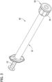
FIG. 2 is an exploded view of an enteral feeding syringe assembly; -
FIG. 3 is a perspective of the enteral feeding syringe assembly showing a cap attached to a syringe of the assembly; -
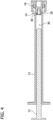
FIG. 4 is a longitudinal section of the assembly ofFig. 2 ; -
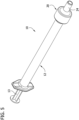
FIG. 5 is a perspective of the enteral feeding syringe assembly showing an enteral feeding connector attached to the syringe of the assembly; -
FIG. 6 is a longitudinal section of the assembly ofFig. 4 ; -
FIG. 7 is an enlarged fragmentary perspective of the syringe; -
FIG. 8 is an enlarged fragmentary elevation of a portion ofFig. 3 ; -
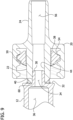
FIG. 9 is an enlarged fragmentary elevation of a portion ofFig. 5 ; -
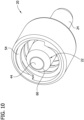
FIG. 10 is a perspective of the enteral feeding connector; and -
FIG. 11 is a perspective of the cap. - Corresponding reference characters indicate corresponding parts throughout the drawings.
- Referring to
Figs. 2-6 , an enteral feeding syringe assembly is generally indicated at 10. The syringe assembly is configured to fluidly connect to a fluid conduit (e.g., a feeding tube) or a reservoir (e.g., medical tubing, bottle, nutrient bag, etc.) for retrieving fluid from the fluid reservoir or delivering fluid to a subject through the fluid conduit. Thesyringe assembly 10 comprises asyringe 12 including afemale fitting 14 on a distal end of the syringe for connecting to a complementary male connector. Theassembly 10 may further comprise acap 16 including a male connector portion 18 (Fig. 4 ) for providing a sealed connection with thefemale fitting 14 of thesyringe 12 when the cap is secured (e.g., threaded) onto the syringe. Alternatively, anenteral feeding connector 20 may include a male connector portion 22 (Fig. 6 ) for providing a sealed connection with thefemale fitting 14 on thesyringe 12 when the enteral feeding connector is secured (e.g., threaded) onto the female fitting of the syringe. When theenteral feeding connector 20 is properly secured to thesyringe 12, atube connector portion 24 of the enteral feeding connector can be connected to a fluid conduit or reservoir to fluidly connect the syringe to the fluid conduit or reservoir. Aplunger 13 can be received in a barrel of thesyringe 12 and used to discharge fluid from the syringe and to draw fluid into the syringe. In the illustrated embodiment, thefemale fitting 14 is formed integrally with a remainder of thesyringe 12. However, thefemale fitting 14 could be formed separately from thesyringe 12 and suitably attached to the syringe. - Referring to
Fig. 8 , thefemale fitting 14 of thesyringe 12 may comprise a projectingconnector portion 30 extending from a floor 32 (broadly, "engagement surface") surrounding the projecting connector portion. Thefloor 32 may extend circumferentially around the entirety of theprojecting connector portion 30 and faces axially outward from the syringe. Afluid passage 34 may extend through the projectingconnector portion 30 from an open distal end of the projecting connector portion to aninterior chamber 36 of thesyringe 12. Aconnector shroud 38 may extend around the projectingconnector portion 30. Theshroud 38 of thefemale fitting 14 may include openings 62 (Fig. 7 ), which help to prevent intake of air into theinterior chamber 36 of the syringe. Air inside theshroud 38 that is displaced by thefemale fitting 14 when it enters the shroud to make a fluid connection can exit the shroud through theopenings 62, rather than being forced into thesyringe 12. Keeping air out of thesyringe 12 is desirable. The projectingconnector portion 30 of the female fitting prior to connecting thecap 16 orenteral feeding connector 20 to thesyringe 12 is visible through the opening. Similarly, the connection of the projectingconnector portion 30 to themale connector portion 22 of theenteral feeding connector 20, or to themale connector portion 18 of thecap 16 are visible from the side of thefemale fitting 14 through theopenings 62. Eachopening 62 may extend generally from a location adjacent thefloor 32 of thefemale fitting 14 past a distal tip of the projectingconnector portion 30 exposing an entire length of the projecting connector portion through the opening. In the illustrated embodiment, there are twoopenings 62. However, other numbers ofopenings 62 are within the scope of the present disclosure. Further, it is envisioned that theopenings 62 could be omitted without departing from the scope of the present disclosure. - A
circumferential side wall 40 of the projectingconnector portion 30 may be configured for sealing engagement with respectiveinner surfaces male connector portions cap 16 andenteral feeding connector 20, respectively (Figs. 8-11 ). For instance, thecircumferential side wall 40 of the projectingconnector portion 30 may have a continuous profile such that the projecting connector portion is free of any channels or grooves in the outer surface of the projecting connector portion. The projectingconnector portion 30 may taper from thefloor 32 of thefemale fitting 14 to a distal end of the projecting connector portion. Anouter surface 48 of theconnector shroud 38 includesthreads 50 for engagingthreads 52 on an inner surface of thecap 16, orthreads 54 on an inner surface of theenteral feeding connector 20 for securely engaging thefemale fitting 14 with either the cap or the enteral feeding connector. Thecircumferential side wall 40 of the projectingconnector portion 30 engages and seals with an interior surface ofinner surface 42 of themale connector 18 when thecap 16 is attached, or engages and seals with theinner surface 44 of themale connector portion 22 of the feedingconnector 20 depending upon whether the cap or feeding connector is connected to thesyringe 12. In addition, arim 58 of themale connector portion 18 of thecap 16, and arim 60 of themale connector portion 22 of theenteral feeding connector 20 may engage and seal with thefloor 32 of thefemale fitting 14 of thesyringe 12 when either the cap or the enteral feeding connector are attached to the syringe. Connection of thefemale fitting 14 to themale connector portion 22 of theenteral feeding connector 20 establishes fluid communication between thefluid passage 34 in thesyringe 12 and afluid passage 56 in the enteral feeding connector for placing theinterior chamber 36 of thesyringe 12 in fluid communication with a fluid conduit or reservoir connected to thetube connector portion 24 of the enteral feeding connector. Moreover, the engagement between thefemale fitting 14 of thesyringe 12 and themale connector portion 22 ofenteral feeding connector 20 provides both a sealed connection along thecircumferential side wall 40 of the projectingconnector portion 30 with theinner surface 44 of themale connector portion 22 and a sealed connection extending around the projecting connector portion along thefloor 32 of the female fitting. Thus, a sealed connection is established along two separate surfaces of thefemale fitting 14. Therefore, a fluid tight connection is ensured when theenteral feeding connector 20 is attached to thesyringe 12. It will be appreciated that the sealing reception of the projectingconnector portion 30 in thefluid passage 56 effectively reverses the male/female connection of the prior art (Fig. 1 ). However, the present invention provides additional sealing by sealing engagement of therim 58 with thefloor 32. - Referring to
Figs. 4 ,8 , and11 , thecap 16 may comprise themale connector portion 18 including apassage 66 extending through the male connector portion, and anannular portion 68 surrounding the male connector portion. Thecap 16 may include a grip portion 70 (Figs. 3 and11 ) for manipulating the cap. Thecap 16 is configured to cover thefemale fitting 14 of thesyringe 12 and block thefluid passage 34 of the projectingconnector portion 30 when the enteralfeeding syringe assembly 10 is not being used. When it is desired to use the enteralfeeding syringe assembly 10, thecap 16 can be removed from thefemale fitting 14 of thesyringe 12 and theenteral feeding connector 20 can be attached to the female fitting. - In use, the enteral
feeding syringe assembly 10 places thesyringe 12 in fluid communication with a fluid reservoir for retrieving fluid from the fluid reservoir. Alternatively, the enteralfeeding syringe assembly 10 can place thesyringe 12 in fluid commination with a fluid conduit to deliver fluid to the fluid conduit. The engagement between thefemale fitting 14 of thesyringe 12 and themale connector portion 22 ofenteral feeding connector 20 ensures that a fluid tight connection is produced when the enteral feeding connector is attached to the syringe. No portion of the syringe volume is occupied by a mating connector. Therefore the volume of fluid in the syringe is always constant, even after connection to the enteral feeding connector is made. - Having described embodiments of the invention in detail, it will be apparent that modifications and variations are possible without departing from the scope of the invention defined in the appended claims.
- When introducing elements of the present invention or the preferred embodiments thereof, the articles "a", "an", "the" and "said" are intended to mean that there are one or more of the elements. The terms "comprising", "including" and "having" are intended to be inclusive and mean that there may be additional elements other than the listed elements.
- The scope of the invention is solely defined by the appended claims.
Claims (9)
- An enteral feeding syringe (12), comprising an engagement surface (32), a projecting connector portion (30) extending from the engagement surface (32), a shroud (38) extending around the projecting connector portion (30), and an interior chamber (36) disposed within the syringe (12), the projecting connector portion (30) including an exterior circumferential wall (40) and a fluid passage (34) extending through the projecting connector portion (30), the fluid passage (34) being in fluid communication with the interior chamber (36) of the syringe (12),
characterized in that the shroud (38) comprises a threaded outer surface for mating with threads (54) on an inner surface of a connector (20) and a beveled inner surface for receiving a male connector portion (22) having a frustoconical outer surface. - The syringe (12) of claim 1, wherein the shroud (38) defines an opening (62) extending from a location adjacent the engagement surface (32) past a distal tip of the projecting connector portion (30) exposing the projecting connector portion (30).
- The syringe (12) of claim 2, wherein the opening (62) has a height and the projecting connector portion (30) has a length, the height of the opening (62) being greater than the length of the projecting connector portion (30) such that an entirety of the length of the projecting connector portion (30) is exposed through the opening (62).
- An enteral feeding syringe assembly (10) comprising:a syringe (12) according to claim 1; anda connector (20) configured for attachment to the syringe (12) to connect the syringe (12) to a fluid conduit or reservoir, the connector (20) comprising the male connector portion (22) including a rim (60) and a passage (56) extending through the male connector portion (22),the projecting connector portion (30) of the syringe (12) being sized and shaped to be received in the male connector portion (22) of the connector (20) when the connector (20) is attached to the syringe (12) such that the exterior wall (40) of the projecting connector portion (30) sealingly engages the male connector portion (22) within the passage (56) of the male connector portion (22) and the rim (60) of the male connector portion (22) engages the engagement surface (32) of the syringe (12) sealing the male connector portion (22) around the projecting connector portion (30) the threaded outer surface of the shroud (38) is for mating with threads (54) on the inner surface of the connector (20).
- The assembly (10) of claim 4, wherein the engagement surface (32) extends circumferentially around the projecting connector portion (30).
- The assembly (10) of claim 4, wherein the engagement surface (32) faces axially outward of the syringe (12).
- The assembly (10) of claim 4, further comprising an opening (62) in the shroud (38), a height of the opening (62) being greater than a length of the projecting connector portion (30) such that an entirety of the length of the projecting connector portion (30) is exposed through the opening (62).
- The assembly (10) of claim 4, wherein the connector (20) comprises a tube connector portion (24) integrally formed with the male connector portion (22) and configured for connecting to a medical tube.
- The assembly (10) of claim 4, further comprising a cap (16) for attachment to the syringe (12) to cover the fluid passage (34) in the projecting connector portion (30) of the syringe (12), the cap (16) comprising a male connector portion (18) including a rim (58), the male connector portion (18) of the cap receiving the projecting connector portion (30) of the syringe (12) when the cap (16) is attached to the syringe (12) such that the rim (58) of the male connector portion (18) of the cap engages the engagement surface (32) of the syringe (12) sealing the male connector portion (18) of the cap (16) around the projecting connector portion (30).
Applications Claiming Priority (2)
| Application Number | Priority Date | Filing Date | Title |
|---|---|---|---|
| US201562174414P | 2015-06-11 | 2015-06-11 | |
| PCT/US2016/036306 WO2016200857A1 (en) | 2015-06-11 | 2016-06-08 | Enteral feeding syringe assembly |
Publications (3)
| Publication Number | Publication Date |
|---|---|
| EP3307350A1 EP3307350A1 (en) | 2018-04-18 |
| EP3307350B1 true EP3307350B1 (en) | 2025-05-14 |
| EP3307350C0 EP3307350C0 (en) | 2025-05-14 |
Family
ID=56148708
Family Applications (1)
| Application Number | Title | Priority Date | Filing Date |
|---|---|---|---|
| EP16730965.7A Active EP3307350B1 (en) | 2015-06-11 | 2016-06-08 | Enteral feeding syringe assembly |
Country Status (4)
| Country | Link |
|---|---|
| US (1) | US10130770B2 (en) |
| EP (1) | EP3307350B1 (en) |
| CA (1) | CA2988747C (en) |
| WO (1) | WO2016200857A1 (en) |
Families Citing this family (7)
| Publication number | Priority date | Publication date | Assignee | Title |
|---|---|---|---|---|
| US10149940B2 (en) * | 2013-07-09 | 2018-12-11 | Nipro Corporation | Connector for fluid, and syringe |
| JP6694501B2 (en) * | 2015-07-14 | 2020-05-13 | ネオメッド, インクNeomed, Inc. | Dosage control joint for enteral fluid flow |
| US20180000694A1 (en) * | 2015-07-14 | 2018-01-04 | Neomed, Inc. | Enteral syringe having angled connector or body having a minimum dimension |
| US10682287B2 (en) | 2015-07-14 | 2020-06-16 | Neomed, Inc. | Dosing control coupling for enteral fluid transfer and enteral couplings and syringes |
| US20210315775A1 (en) * | 2018-09-07 | 2021-10-14 | Becton, Dickinsn And Company | Syringe assembly and adapter member |
| GB201907070D0 (en) | 2019-05-20 | 2019-07-03 | Metis Design Bv | Connector for a gastrostomy device |
| US20250235388A1 (en) * | 2024-01-19 | 2025-07-24 | Avent, Inc. | Combination Connector and System for Enteral Feeding |
Citations (2)
| Publication number | Priority date | Publication date | Assignee | Title |
|---|---|---|---|---|
| US20070129705A1 (en) * | 2005-12-01 | 2007-06-07 | Medrad, Inc. | Fluid delivery system, fluid path, and medical connector for use with the fluid delivery system and fluid path |
| US20120022457A1 (en) * | 2010-07-23 | 2012-01-26 | Medela Holding Ag | Enteral Feeding Connector and Assembly |
Family Cites Families (51)
| Publication number | Priority date | Publication date | Assignee | Title |
|---|---|---|---|---|
| US4240422A (en) * | 1978-10-23 | 1980-12-23 | American Hospital Supply Corporation | Syringe with needle and method of attaching same |
| US4390017A (en) | 1981-08-07 | 1983-06-28 | Harrison Eugene O | Enteral feeding system |
| US4668225A (en) | 1985-12-23 | 1987-05-26 | Superior Healthcare Group, Inc. | Gastrostomy tube and gastrostomy-jejunal feeding tube combination |
| US5100394A (en) | 1988-01-25 | 1992-03-31 | Baxter International Inc. | Pre-slit injection site |
| US5113571A (en) | 1990-01-29 | 1992-05-19 | Manska Wayne E | Method of manufacturing a connector for medical devices |
| USD340111S (en) | 1990-03-07 | 1993-10-05 | Terumo Kabushiki Kaisha | Catheter |
| US5184742A (en) | 1990-06-18 | 1993-02-09 | Boc Health Care, Inc. | Deadender cap for luer fitting |
| JPH0614756Y2 (en) | 1991-06-26 | 1994-04-20 | 株式会社アルテ | Assembled dual chamber syringe |
| US5312377A (en) * | 1993-03-29 | 1994-05-17 | Dalton Michael J | Tapered luer connector |
| USD381075S (en) | 1995-08-16 | 1997-07-15 | Abbott Laboratories | Tubing adapter |
| USD401324S (en) | 1997-03-07 | 1998-11-17 | Pharmacia & Upjohn Ab | Syringe |
| USD440304S1 (en) | 1999-10-27 | 2001-04-10 | Corvascular, Inc. | Direct fluid-delivery system |
| US6699233B2 (en) | 2000-04-10 | 2004-03-02 | Scimed Life Systems, Inc. | Locking catheter |
| AU2001274990A1 (en) * | 2000-05-25 | 2001-12-03 | Johnnie M. Johnson | Adapter and method of attachment for "luer lok" receptacles |
| US7316669B2 (en) * | 2002-08-22 | 2008-01-08 | Baxa Corporation | Protective cap for medical male luer fittings |
| US6736799B1 (en) | 2000-10-24 | 2004-05-18 | Vita Licensing, Inc. | Delivery device for biological composites and method of preparation thereof |
| US20060047251A1 (en) | 2002-10-22 | 2006-03-02 | Philip Bickford Smith | Medical small-bore tubing system and kit |
| WO2004037329A1 (en) | 2002-10-24 | 2004-05-06 | Terumo Kabushiki Kaisha | Method of producing syringe, cap, and prefilled syringe |
| USD492030S1 (en) | 2003-04-23 | 2004-06-22 | Novartis Nutrition Ag | Y-port |
| FR2863162B1 (en) | 2003-12-05 | 2006-12-08 | Vygon | MALE FITTINGS AND FEMALE FITTINGS FOR REALIZING LIQUID TRANSMISSION CONNECTIONS, IN PARTICULAR FOR ENTERALE NUTRITION LINES |
| SE0401569D0 (en) | 2004-06-17 | 2004-06-17 | Gambro Lundia Ab | applicator |
| DE202004012714U1 (en) | 2004-08-12 | 2004-11-04 | Smiths Medical Deutschland Gmbh | Luer lock connector for medical devices |
| JP4943690B2 (en) | 2005-10-27 | 2012-05-30 | 前田産業株式会社 | Syringe holder and syringe |
| USD543278S1 (en) | 2005-12-28 | 2007-05-22 | Terumo Kabushiki Kaisha | Syringe |
| JP5364898B2 (en) | 2006-03-08 | 2013-12-11 | ドティッド・インテレクチュアル・プロパティ・リミテッド・ライアビリティ・カンパニー | Antifouling cover for fluid connections |
| USD578210S1 (en) | 2006-03-14 | 2008-10-07 | Hisamitsu Pharmaceutical Co., Inc. | Injector |
| AP2008004667A0 (en) | 2006-05-05 | 2008-12-31 | Retractable Technologies Inc | Syringe with recessed nose for use with frontal attachments |
| US20080045929A1 (en) | 2006-08-18 | 2008-02-21 | Birnbach David J | Method and infusion tubing connection system for selective administration of medicaments in the body |
| US20080140055A1 (en) | 2006-12-08 | 2008-06-12 | Utah Medical Products, Inc. | Lockable enteral feeding adapter |
| US20080312640A1 (en) | 2007-06-14 | 2008-12-18 | Sabin Corporation | Modified luer fittings for feeding tube adapter |
| JP4999604B2 (en) | 2007-08-23 | 2012-08-15 | 日本コヴィディエン株式会社 | Connector connection structure |
| IL186290A0 (en) | 2007-09-25 | 2008-01-20 | Medimop Medical Projects Ltd | Liquid drug delivery devices for use with syringe having widened distal tip |
| US8628509B2 (en) | 2009-05-11 | 2014-01-14 | Abbott Laboratories | Enteral connectors and systems |
| US9814870B2 (en) | 2010-08-17 | 2017-11-14 | Becton, Dickinson And Company | Non-luer connectors |
| US9283148B2 (en) | 2011-03-07 | 2016-03-15 | Medela Holding Ag | Multi-purpose syringe |
| US9433768B2 (en) | 2011-03-25 | 2016-09-06 | Becton, Dickinson And Company | Drug delivery connectors |
| US9220833B2 (en) | 2011-06-27 | 2015-12-29 | Smiths Medical Asd, Inc. | Medicament infusion systems |
| JP5873281B2 (en) | 2011-09-29 | 2016-03-01 | 日本コヴィディエン株式会社 | Fistula catheter |
| USD700318S1 (en) | 2011-11-14 | 2014-02-25 | Asalus Medical Instruments Limited | Catheter |
| CA159606S (en) | 2012-10-30 | 2015-01-06 | Santen Pharmaceutical Co Ltd | Intraocular lens implantation device |
| CA151038S (en) | 2013-01-28 | 2014-06-18 | Sulzer Mixpac Ag | Applicator for applying preparations to skin |
| USD739524S1 (en) | 2013-04-22 | 2015-09-22 | Blue Rhino Global Sourcing, Inc. | Injector |
| USD728781S1 (en) | 2013-10-01 | 2015-05-05 | Dentsply International Inc. | Dental material dispenser tip |
| USD728780S1 (en) | 2013-10-01 | 2015-05-05 | Dentsply International Inc. | Dental material dispenser tip |
| USD743025S1 (en) | 2013-10-09 | 2015-11-10 | Barry B. Berler | Safety syringe |
| CA156081S (en) | 2013-10-17 | 2014-11-07 | Otsuka Pharma Co Ltd | Syringe |
| USD747797S1 (en) | 2013-11-14 | 2016-01-19 | Eli Lilly And Company | Injection device |
| USD747473S1 (en) | 2014-01-21 | 2016-01-12 | Fisher & Paykel Healthcare Limited | Dual-connector wye piece |
| USD733870S1 (en) | 2014-03-05 | 2015-07-07 | 3M Innovative Properties Company | Flowable syringe |
| USD748777S1 (en) | 2014-05-19 | 2016-02-02 | Nipro Corporation | Needle introducer catheter |
| USD741476S1 (en) | 2014-06-20 | 2015-10-20 | Otsuka Pharmaceutical Co., Ltd. | Medical syringe |
-
2016
- 2016-06-06 US US15/174,315 patent/US10130770B2/en active Active
- 2016-06-08 CA CA2988747A patent/CA2988747C/en active Active
- 2016-06-08 EP EP16730965.7A patent/EP3307350B1/en active Active
- 2016-06-08 WO PCT/US2016/036306 patent/WO2016200857A1/en not_active Ceased
Patent Citations (2)
| Publication number | Priority date | Publication date | Assignee | Title |
|---|---|---|---|---|
| US20070129705A1 (en) * | 2005-12-01 | 2007-06-07 | Medrad, Inc. | Fluid delivery system, fluid path, and medical connector for use with the fluid delivery system and fluid path |
| US20120022457A1 (en) * | 2010-07-23 | 2012-01-26 | Medela Holding Ag | Enteral Feeding Connector and Assembly |
Also Published As
| Publication number | Publication date |
|---|---|
| CA2988747C (en) | 2023-09-26 |
| US10130770B2 (en) | 2018-11-20 |
| US20160361497A1 (en) | 2016-12-15 |
| CA2988747A1 (en) | 2016-12-15 |
| WO2016200857A1 (en) | 2016-12-15 |
| EP3307350A1 (en) | 2018-04-18 |
| EP3307350C0 (en) | 2025-05-14 |
Similar Documents
| Publication | Publication Date | Title |
|---|---|---|
| US20250120884A1 (en) | Dosing control coupling for enteral fluid transfer | |
| CA2988747C (en) | Enteral feeding syringe assembly | |
| US11065181B2 (en) | Syringe-to-syringe coupler | |
| US20160361235A1 (en) | Adapter assembly for enteral feeding | |
| US10682287B2 (en) | Dosing control coupling for enteral fluid transfer and enteral couplings and syringes | |
| EP3522953B1 (en) | Syringe with enteral connection feature | |
| US10688295B2 (en) | Liquid transfer devices for use with infusion liquid containers | |
| US8777930B2 (en) | Discriminating oral-tip adaptor | |
| CN105797240B (en) | Blunt needle safe drugs delivery system | |
| US11690994B1 (en) | Modular medical connector | |
| CN111295171A (en) | Dual vial adapter assembly including dual exhaust female vial adapter | |
| CN103052415B (en) | For the system and method for injector for medical purpose | |
| US11554258B2 (en) | Syringe with snap-in enteral connection feature | |
| KR102574338B1 (en) | Male fluid connector, female fluid connector and fluid connection system including the same | |
| US20190083359A1 (en) | Pharmaceutical adaptor system and pharmaceutical kit system | |
| ES2657603T3 (en) | Combination of residual low volume syringe / tube and syringe for said syringe / tube combination | |
| WO2015075221A1 (en) | Container system for intravenous therapy | |
| CN104010681A (en) | Disposable syringe | |
| CA2964537A1 (en) | Enteral feeding adapter and method of use | |
| KR101350305B1 (en) | Medicine container with double chamber and disposable syringe including the container | |
| US20180000694A1 (en) | Enteral syringe having angled connector or body having a minimum dimension |
Legal Events
| Date | Code | Title | Description |
|---|---|---|---|
| STAA | Information on the status of an ep patent application or granted ep patent |
Free format text: STATUS: THE INTERNATIONAL PUBLICATION HAS BEEN MADE |
|
| PUAI | Public reference made under article 153(3) epc to a published international application that has entered the european phase |
Free format text: ORIGINAL CODE: 0009012 |
|
| STAA | Information on the status of an ep patent application or granted ep patent |
Free format text: STATUS: REQUEST FOR EXAMINATION WAS MADE |
|
| 17P | Request for examination filed |
Effective date: 20171211 |
|
| AK | Designated contracting states |
Kind code of ref document: A1 Designated state(s): AL AT BE BG CH CY CZ DE DK EE ES FI FR GB GR HR HU IE IS IT LI LT LU LV MC MK MT NL NO PL PT RO RS SE SI SK SM TR |
|
| AX | Request for extension of the european patent |
Extension state: BA ME |
|
| DAV | Request for validation of the european patent (deleted) | ||
| DAX | Request for extension of the european patent (deleted) | ||
| STAA | Information on the status of an ep patent application or granted ep patent |
Free format text: STATUS: EXAMINATION IS IN PROGRESS |
|
| 17Q | First examination report despatched |
Effective date: 20200219 |
|
| GRAP | Despatch of communication of intention to grant a patent |
Free format text: ORIGINAL CODE: EPIDOSNIGR1 |
|
| STAA | Information on the status of an ep patent application or granted ep patent |
Free format text: STATUS: GRANT OF PATENT IS INTENDED |
|
| INTG | Intention to grant announced |
Effective date: 20241204 |
|
| RIN1 | Information on inventor provided before grant (corrected) |
Inventor name: ECKENROTH, TIMOTHY Inventor name: WALKER, SANDRA Inventor name: SWISHER, DAVID RORK |
|
| GRAS | Grant fee paid |
Free format text: ORIGINAL CODE: EPIDOSNIGR3 |
|
| GRAA | (expected) grant |
Free format text: ORIGINAL CODE: 0009210 |
|
| STAA | Information on the status of an ep patent application or granted ep patent |
Free format text: STATUS: THE PATENT HAS BEEN GRANTED |
|
| AK | Designated contracting states |
Kind code of ref document: B1 Designated state(s): AL AT BE BG CH CY CZ DE DK EE ES FI FR GB GR HR HU IE IS IT LI LT LU LV MC MK MT NL NO PL PT RO RS SE SI SK SM TR |
|
| REG | Reference to a national code |
Ref country code: GB Ref legal event code: FG4D |
|
| REG | Reference to a national code |
Ref country code: CH Ref legal event code: EP |
|
| REG | Reference to a national code |
Ref country code: IE Ref legal event code: FG4D |
|
| REG | Reference to a national code |
Ref country code: DE Ref legal event code: R096 Ref document number: 602016092231 Country of ref document: DE |
|
| PGFP | Annual fee paid to national office [announced via postgrant information from national office to epo] |
Ref country code: GB Payment date: 20250627 Year of fee payment: 10 |
|
| U01 | Request for unitary effect filed |
Effective date: 20250606 |
|
| U07 | Unitary effect registered |
Designated state(s): AT BE BG DE DK EE FI FR IT LT LU LV MT NL PT RO SE SI Effective date: 20250616 |
|
| U20 | Renewal fee for the european patent with unitary effect paid |
Year of fee payment: 10 Effective date: 20250628 |
|
| PG25 | Lapsed in a contracting state [announced via postgrant information from national office to epo] |
Ref country code: ES Free format text: LAPSE BECAUSE OF FAILURE TO SUBMIT A TRANSLATION OF THE DESCRIPTION OR TO PAY THE FEE WITHIN THE PRESCRIBED TIME-LIMIT Effective date: 20250514 |
|
| PG25 | Lapsed in a contracting state [announced via postgrant information from national office to epo] |
Ref country code: NO Free format text: LAPSE BECAUSE OF FAILURE TO SUBMIT A TRANSLATION OF THE DESCRIPTION OR TO PAY THE FEE WITHIN THE PRESCRIBED TIME-LIMIT Effective date: 20250814 Ref country code: GR Free format text: LAPSE BECAUSE OF FAILURE TO SUBMIT A TRANSLATION OF THE DESCRIPTION OR TO PAY THE FEE WITHIN THE PRESCRIBED TIME-LIMIT Effective date: 20250815 |
|
| PG25 | Lapsed in a contracting state [announced via postgrant information from national office to epo] |
Ref country code: PL Free format text: LAPSE BECAUSE OF FAILURE TO SUBMIT A TRANSLATION OF THE DESCRIPTION OR TO PAY THE FEE WITHIN THE PRESCRIBED TIME-LIMIT Effective date: 20250514 |
|
| PG25 | Lapsed in a contracting state [announced via postgrant information from national office to epo] |
Ref country code: HR Free format text: LAPSE BECAUSE OF FAILURE TO SUBMIT A TRANSLATION OF THE DESCRIPTION OR TO PAY THE FEE WITHIN THE PRESCRIBED TIME-LIMIT Effective date: 20250514 |
|
| PGFP | Annual fee paid to national office [announced via postgrant information from national office to epo] |
Ref country code: CH Payment date: 20250701 Year of fee payment: 10 |
|
| PG25 | Lapsed in a contracting state [announced via postgrant information from national office to epo] |
Ref country code: RS Free format text: LAPSE BECAUSE OF FAILURE TO SUBMIT A TRANSLATION OF THE DESCRIPTION OR TO PAY THE FEE WITHIN THE PRESCRIBED TIME-LIMIT Effective date: 20250814 |
|
| PG25 | Lapsed in a contracting state [announced via postgrant information from national office to epo] |
Ref country code: IS Free format text: LAPSE BECAUSE OF FAILURE TO SUBMIT A TRANSLATION OF THE DESCRIPTION OR TO PAY THE FEE WITHIN THE PRESCRIBED TIME-LIMIT Effective date: 20250914 |
|
| PG25 | Lapsed in a contracting state [announced via postgrant information from national office to epo] |
Ref country code: SM Free format text: LAPSE BECAUSE OF FAILURE TO SUBMIT A TRANSLATION OF THE DESCRIPTION OR TO PAY THE FEE WITHIN THE PRESCRIBED TIME-LIMIT Effective date: 20250514 |
|
| PG25 | Lapsed in a contracting state [announced via postgrant information from national office to epo] |
Ref country code: CZ Free format text: LAPSE BECAUSE OF FAILURE TO SUBMIT A TRANSLATION OF THE DESCRIPTION OR TO PAY THE FEE WITHIN THE PRESCRIBED TIME-LIMIT Effective date: 20250514 |
|
| PG25 | Lapsed in a contracting state [announced via postgrant information from national office to epo] |
Ref country code: SK Free format text: LAPSE BECAUSE OF FAILURE TO SUBMIT A TRANSLATION OF THE DESCRIPTION OR TO PAY THE FEE WITHIN THE PRESCRIBED TIME-LIMIT Effective date: 20250514 |
|
| PG25 | Lapsed in a contracting state [announced via postgrant information from national office to epo] |
Ref country code: MC Free format text: LAPSE BECAUSE OF FAILURE TO SUBMIT A TRANSLATION OF THE DESCRIPTION OR TO PAY THE FEE WITHIN THE PRESCRIBED TIME-LIMIT Effective date: 20250514 |
|
| PLBE | No opposition filed within time limit |
Free format text: ORIGINAL CODE: 0009261 |
|
| STAA | Information on the status of an ep patent application or granted ep patent |
Free format text: STATUS: NO OPPOSITION FILED WITHIN TIME LIMIT |
|
| REG | Reference to a national code |
Ref country code: CH Ref legal event code: L10 Free format text: ST27 STATUS EVENT CODE: U-0-0-L10-L00 (AS PROVIDED BY THE NATIONAL OFFICE) Effective date: 20260325 |
|
| PG25 | Lapsed in a contracting state [announced via postgrant information from national office to epo] |
Ref country code: IE Free format text: LAPSE BECAUSE OF NON-PAYMENT OF DUE FEES Effective date: 20250608 |
|
| 26N | No opposition filed |
Effective date: 20260217 |
|
| U1N | Appointed representative for the unitary patent procedure changed after the registration of the unitary effect |
Representative=s name: MARKS & CLERK LLP; GB |