EP3307073B2 - Removing the spinal column from a half-carcass of a slaughtered animal - Google Patents
Removing the spinal column from a half-carcass of a slaughtered animal Download PDFInfo
- Publication number
- EP3307073B2 EP3307073B2 EP16728322.5A EP16728322A EP3307073B2 EP 3307073 B2 EP3307073 B2 EP 3307073B2 EP 16728322 A EP16728322 A EP 16728322A EP 3307073 B2 EP3307073 B2 EP 3307073B2
- Authority
- EP
- European Patent Office
- Prior art keywords
- carcass
- spinal column
- concavity
- offset
- geometrical feature
- Prior art date
- Legal status (The legal status is an assumption and is not a legal conclusion. Google has not performed a legal analysis and makes no representation as to the accuracy of the status listed.)
- Active
Links
Images

Classifications
-
- A—HUMAN NECESSITIES
- A22—BUTCHERING; MEAT TREATMENT; PROCESSING POULTRY OR FISH
- A22B—SLAUGHTERING
- A22B5/00—Accessories for use during or after slaughtering
- A22B5/0017—Apparatus for cutting, dividing or deboning carcasses
- A22B5/0035—Deboning or obtaining boneless pieces of meat from a carcass
-
- A—HUMAN NECESSITIES
- A22—BUTCHERING; MEAT TREATMENT; PROCESSING POULTRY OR FISH
- A22B—SLAUGHTERING
- A22B5/00—Accessories for use during or after slaughtering
- A22B5/0017—Apparatus for cutting, dividing or deboning carcasses
- A22B5/0041—Electronic, robotic or computer assisted cutting, dividing or deboning carcasses
-
- A—HUMAN NECESSITIES
- A22—BUTCHERING; MEAT TREATMENT; PROCESSING POULTRY OR FISH
- A22B—SLAUGHTERING
- A22B5/00—Accessories for use during or after slaughtering
- A22B5/20—Splitting instruments
- A22B5/201—Removing the spinal cord or other nervous tissues
-
- A—HUMAN NECESSITIES
- A22—BUTCHERING; MEAT TREATMENT; PROCESSING POULTRY OR FISH
- A22C—PROCESSING MEAT, POULTRY, OR FISH
- A22C17/00—Other devices for processing meat or bones
- A22C17/004—Devices for deboning meat
-
- A—HUMAN NECESSITIES
- A22—BUTCHERING; MEAT TREATMENT; PROCESSING POULTRY OR FISH
- A22C—PROCESSING MEAT, POULTRY, OR FISH
- A22C17/00—Other devices for processing meat or bones
- A22C17/0073—Other devices for processing meat or bones using visual recognition, X-rays, ultrasounds, or other contactless means to determine quality or size of portioned meat
- A22C17/0086—Calculating cutting patterns based on visual recognition
Definitions
- the present invention relates to the slaughtering industry where slaughtered animals are cut along the median plane to provide a pair of half-carcasses, and the spinal column, also referred to as the vertebral column, is removed from the half-carcasses.
- US 8,915,773 discloses a method for separation of the spinal column from a carcass middle part.
- the method disclosed therein comprises the steps of determining a cutting path for a cutting device for the separation of the spinal column from the carcass middle part; separating the spinal column from the carcass middle part by causing a relative movement between the middle part and the cutting device and simultaneously causing the cutting device to engage the carcass middle.
- the method includes: optically scanning the middle part to provide a scan of an outer surface of the carcass middle part and identifying and locating the spinal canal in the spinal column on the basis of digital processing.
- the cutting path is subsequently to the scanning determined on the basis of the position of the spinal canal and the cutting is carried subsequent to the scanning and determination of the cutting path.
- the method disclosed in US 8,915,773 requires that the spinal cord is optically detectable and the accuracy of the method therefore depends on the accuracy with which the carcass has been split along the median plane and reveals the spinal canal.
- the method disclosed in US 8,915,773 fails to provide a cutting path and removal of the spinal column is to be performed by other means such as manually resulting in increased labour cost.
- the split may typically be offset typically up till 10 mm from a perfect split and/or it may further be angled relatively the median plane.
- the spinal column is detectable, the use of the position of the spinal column may lead to a relative high offset of the cutting plane which may be offset too much or too little resulting in that either too much meat or too little bone is removed.
- an improved method for removing the spinal column would be advantageous, and in particular a more efficient and/or reliable method for removing the spinal column would be advantageous.
- the invention provides a method of removing, at least partly, the spinal column from a half-carcass of a slaughtered animal that has been cut substantially along the median plane of the slaughtered animal thereby providing a median cut surface of the half-carcass according to claim 1.
- the present invention resides inter alia in the concept of locating an anatomical structure and determining a characteristic feature, and the anatomical structure and the characteristic feature may be seen as fixtures or waypoints relatively to which the cutting path is defined. While the anatomical structure is located in the sense that it represents an image of a well-defined anatomical element of the bones in half-carcass, the characteristic feature is determined as it relates to geometry of a point or part of the bones in the half-carcass.
- the method of the invention thus bases the location of the cutting path on an anatomical structure on the ventral side of the half-carcass, e.g. the concavity defined in relation to joints between rib heads and a characteristic geometrical feature.
- the cutting path passes through a position being offset a predetermined first offset to the located anatomical feature and a position in the half-carcass being offset a predetermined second offset from the characteristic geometrical feature.
- the offset may be determined by an operator by adjusting the offset(s) until a desired cut is produced; once the offsets are determined, they are typically used for subsequent cuts as predetermined offsets.
- the offsets may take typical values ranging up to e.g. 30mm, although the invention is not considered limited to offsets being within this range. Further, some embodiments of the uses an angle as offset.
- the characteristic geometrical feature is a position and the second offset may be a predetermined orientated distance from the characteristic geometrical feature.
- orientated distance it typically meant to denote a vector having a direction relative to a fix orientation (e.g. horizontal) and having a length.
- the anatomical structure is a concavity defined in relation to the joint between rib heads and thoracic vertebrae, top of rib heads, or a concavity below the rib head.
- the characteristic geometrical feature is a spinous process, the spatial orientation of the median cut surface, the spinal canal, the upper most position of the spinal column, or the tangent to the surface between the upper most position of the spinal column and the anatomical structure.
- locating the anatomical structure is done using an optical locator providing data on a zone of the half-carcass, preferably including at least the concavity.
- the characteristic geometrical feature is determined using an optical locator.
- the anatomical feature is located using an optical locator.
- Locating the anatomical feature is performed optically, by suitable means to provide data on a zone of the half-carcass, preferably including at least the concavity.
- Optical locators preferably, by use of suitable means, include, for example cameras and/or equipment, which generate, are configured for, or are capable of taking video images, stereo vision, scanning, time-of-flight measurements, X-rays, and/or structured light as well.
- the characteristic geometrical feature and the anatomical feature are determined using devices adapted to carry out optical determinations, typically by use of means adapted to this.
- the method of the invention can be performed on half-carcasses when arranged suspended in an orientation or when supported by a conveyor.
- the method comprises moving the half-carcass, while supported by a conveyor, along a longitudinal direction of the spinal column, illuminating the ventral side of the moving half-carcass, and obtaining image data on the zone of the half-carcass, preferably including at least the concavity.
- illuminating the ventral side of the half-carcass includes projecting a beam of light defining a plane of light transverse to the direction of movement, and receiving projected light reflected from the half-carcass with a camera situated outside the plane of light to obtain profile information on the zone of the half-carcass, preferably including at least the concavity.
- the half-carcass may be arranged on a conveyor and means may be provided for stabilising the position of the half-carcass on the conveyor. Accordingly, in preferred embodiments of a method according to the present invention may the half-carcass may be arranged on a conveyor and the position of the half-carcass on the conveyor may be stabilized.
- the half-carcass may preferably be arranged suspended in an orientation, and a method according to preferred embodiment of the invention may further comprise:
- the conveyor may preferably comprise an encoder providing data on movements of the conveyer and thereby the half-carcass.
- the spatial orientation of the median cut surface is determined optically, e.g. by using optical means, including e.g. taking video images, stereo vision, scanning, time-of-flight measurements, X-rays, structured light, configured to determine spatial orientation of the median cut.
- optical means including e.g. taking video images, stereo vision, scanning, time-of-flight measurements, X-rays, structured light, configured to determine spatial orientation of the median cut.
- the method of the invention is carried out so that preferably immediately after a first portion of the concavity has been located and the spatial orientation of a portion of the median cut surface at the portion of the concavity has been determined, the located first portion will be cut concurrently with a second portion of the concavity will be located. This sequence is repeated until the spinal column is at least partly removed and ensures a fast and efficient removal of the spinal column.
- the present invention is capable of handling both left and right sides of half-carcasses.
- Cutting to remove the spinal column can be performed using e.g. a circular cutting blade, a reciprocating cutting blade, an endless cutting blade or water-jet cutting.
- a carcass having been cut substantially along the median plane is used to mean that the carcass has been cut along the median plane so that each of the thereby to half-carcass comprises a section of the spinal column.
- Half-carcass is used to mean an piece of meat including a part of the spinal column.
- Longitudinal orientation or direction of the spinal column is used to mean the orientation from head to tail of the animal or vice versa.
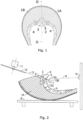
- Figure 1 shows a cross section of the carcass of a slaughtered animal.
- a dotted line II-II indicates the medial plane 2 along which the carcass is to be cut to provide two half-carcasses 1A and 1B.
- the spinal column 3 with the spinal canal 5 and ribs 4 connected to the spinal column are seen.
- Figure 2 shows the half-carcass 1A supported by a conveyor 8.
- a scanner 10 projects light towards a zone of the ventral side of the half-carcass 1A, the zone including at least the concavity 7 defined in relation to joints between rib heads and the spinal column 3 of the half-carcass 1A.
- Light is reflected from the carcass and is received by a light receiver such as a camera in the scanner 10, and image data from the camera is processed to identify and locate the concavity 7.
- the half-carcass 1A, 1B may be provided in such a manner that it only has ribs along a part of the longitudinal direction thereof and/or the half-carcass 1A, 1B is a section without rib(s).
- a method (or a part of a method) according to the invention is applied for the section comprising ribs and in the region not comprising ribs, e.g. the concavity between spinal column and a transverse process may be used for determining a cutting path; this procedure is disclosed inter alia in connection with fig. 8 .
- the method of removing, at least partly, the spinal column from a half-carcass 1A, 1B of a slaughtered animal that has been cut substantially along the median plane 2 of the slaughtered animal thereby providing a median cut surface 6 of the half-carcass (1A, 1B) may comprise the steps of locating, on the ventral side of the half-carcass 1A, 1B, an anatomical structure 7 defined in relation to joints between rib heads and the spinal column 3 of the half-carcass 1A, 1B, and determining a characteristic geometrical feature 15 of e.g. the median cut surface 6 and/or of the ventral side of the half-carcass 1A, 1B.
- locating and determining both refers to a situation where an image is obtained of the half-carcass 1A, 1B and that locating is used to indicate that the position of well-defined anatomical structure is located in the image, and the determining is used to indicate that the feature relates to the geometry of a point or part of the bones in the half-carcass.
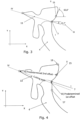
- the characteristic geometrical feature 15 may as indicated in figures 3 and 4 comprise a position ( fig. 4 ) on and/or a spatial orientation ( fig. 3 ) of at least a part of the spinal column.
- the cutting along a cutting path 13 is defined in relation to those two features said anatomical structure (7) so as to, at least partly, remove the spinal column from the half-carcass 1A, 1B.
- the cutting path 13 passes through a position being offset a predetermined first offset to the located anatomical feature 7 and a position in the half-carcass 1A, 1B being offset a predetermined second offset from the characteristic geometrical feature 15.
- the offset may typically be predetermined by an operator operating the cutting equipment input a value for the first and the second offset to cutting device (controlled by a computer). The operator evaluates the cut provided and if the initial input offset values provides a cut which is not the operator's satisfaction due to e.g. too much removal of meat or to little removal of spinal column the operator adjust the first and/or second offset. This procedure is continued until the operator is satisfied with the cutting. After that, the offsets typically remains unchanged until an operator finds reason to change one or more of the offsets.
- the offsets typically are predetermined by an operator, the offsets may alternatively be predetermined in an automated manner, where vision equipment evaluates the cutting and changes the offsets until a desired result is obtained.
- the characteristic geometrical feature may be a spatial orientation.
- the characteristic geometrical feature 15 is the angle of the tangent in a point on the spinal column which in the example of fig. 3 is shown to be 65.5° and the predetermined offset angle is 15.7° (as indicated in fig. 3 , reference III).
- the cutting is made so that the cutting path is angled 65.5°+15.7° to the tangent in the point considered.
- the characteristic geometrical feature 15 is the spatial orientation of the median cut surface 6, and the second offset is a predetermined angle V with the characteristic geometrical feature.
- the characteristic geometrical feature 15 is a position and the first and second offset is a predetermined orientated distance from the characteristic geometrical feature 15.
- the characteristic geometrical feature 15 is typically selected as a position on the spinal column which is easy recognisable in an image and may e.g. be selected as the point positioned a certain distance from e.g. the upper most position of the spinal column 16.
- the location of the anatomical structure may be carried out in a similar manner.
- the anatomical structure 7 is selected as a concavity defined in relation to the joint between rib heads and thoracic vertebrae, top of rib heads, or a concavity below the rib head 17.
- the characteristic geometrical feature 15 is selected as spinous process, the spatial orientation of the median cut surface 6, spinal canal, the upper most position of the spinal column 16, or the tangent to the surface between the upper most position of the spinal column 16 and the anatomical structure 7.
- FIG 5A shows a half vertebra of the spinal column 3 and a rib 4 in the half-carcass. It is desired to cut along a plane cutting path defined by the line L 2 intersecting the concavity 7 such as its "deepest" point and the point (X B , Y B ) near the tip of the spinous process of the vertebra.
- the point (X A , Y A ) is identified and located optically by devices/means corresponding to the optical scanner 10 used to locate the concavity 7 whereby the cutting path is determined, or the cutting path 13 is determined based on the spatial orientation of the median cut surface 6, which is determined optically.
- the cutting path 13 is then determined as the plane intersecting the concavity 7 and forming a predetermined angle V with the median cut surface 6.
- the cutting path 13 herein is disclosed as a straight line, the cutting path may be curved. For instance, in cases where curved saw is used, the cutting path may reflect the shape of the knife.
- the predetermined angle V of the cutting path 13 relative to the median cut surface 6 depends on e.g. the species of the animal and/or the size of the animal and/or the position along the spinal column.
- the location and angle of the cutting path 13 may be further adjusted manually or adaptively.
- Figure 2 shows the cutting path 13A as determined automatically, and alternative cutting paths 13B and 13C are examples of further adjusted cutting paths.
- Figure 5B illustrates steps in the process of determining the cutting path 13.
- the coordinates (X A , Y A ) of the concavity 7 are determined as mentioned above, preferably by optical locator/means.
- the predetermined angle (V) of the cutting path typically depends on the species of the animal and/or the size of the animal and/or the position along the spinal column 3.
- an offset may be added to one or both of the coordinates (XA, YA), for instance to alter the orientation of the line L2 if so desired.
- the notations "f(V, ⁇ 1 )" and “g(X A , Y A )” are used to reference two functional relations, typically being mathematical relations, "f” and "g".
- Cutting can be performed by using cutting device known in the art, such as a circular cutting blade 12 driven by a motor 11, a reciprocating cutting blade 12 driven by a motor 11, an endless cutting blade 12 driven by a motor 11 or a water-jet cutting device.
- the motor 11 with the cutting blade 12 is moved by a robotic arm (not shown) controlled by the controller so that the cutting blade follows the determined cutting path 13 to eventually remove the spinal column at least partly.
- the interaction of the cutting blade with the half-carcass may cause the half-carcass to move on the conveyor which may cause the cutting blade to follow a wrong cutting path.
- the present invention also includes embodiments in which the half-carcass is not moved during cutting, in which case the cutting blade is moved along the longitudinal direction of the half-carcass. Further, the cutting may be performed from ventral side, towards the ventral side or combinations thereof.
- the straight line 13 indicates a cut provided with e.g. a cutting blade formed as flat disc thereby providing a straight cut.
- the curved line 13 illustrates a cut provided with a curved cutting blade e.g. with a band saw.
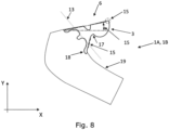
- FIG. 8 schematically illustration of a cutting path in section of a half-carcass 1A, 1B not comprising rib(s) - the section not comprising rib(s) may be a separate section or a section of a half-carcass 1A, 1B not comprising rib(s). Such a section is in general located near the pelvis/hip.
- fig. 8 three different options for a characteristic geometrical feature 15 are illustrated, which may be combined or used alone.
- the method preferably includes locating, on the ventral side of the half-carcass 1A, 1B, the anatomical structure 17 defined in relation in relation to the concavity (17 in fig. 8 ) between the spinal column 3 and the transverse process 18.
- the method comprising determining a characteristic geometrical feature 15 of the median cut surface 6 and/or of the ventral side of the half-carcass 1A, 1B.
- the characteristic geometrical feature 15 comprising a position on and/or a spatial orientation of at least a part of the spinal column
- a position could be the edge indicated by a circle in fig. 8 and spatial orientation could be the orientation of the median cut surface 6 to e.g. horizontal (in figure 8 angle indicated relatively to horizontal) and/or the orientation of the edge, the position and/or orientation (e.g. typically relatively to horizontal or in relation to the coordinate system X-Y which may be the same) of a flat part of the transverse process 18.
- the position of the flat part of the transverse process typically a midpoint (as seen in the cross sectional view of fig. 8 ) of the flat part is taken as the position.
- the method comprising cutting along a cutting path 13, the cutting path being defined in relation to said anatomical structure 17 and said characteristic geometrical feature 15 of the median cut surface 6 and/or of the ventral side of the half-carcass, so as to remove, at least partly, the spinal column from the half-carcass 1A, 1B, as otherwise presented herein.
- the invention can be implemented by use of/means of hardware, software, firmware or any combination of these.
- the invention or some of the features thereof can also be implemented as software running on one or more data processors and/or digital signal processors.
- the imaging is based on electromagnetic radiation which may be characterised as making use of reflection of electromagnetic radiation or transmission of electromagnetic radiation.
- x-ray radiation is applied.
- An x-ray source transmit x-ray and a detector is arranged to detect x-rays transmitted through the half-carcass.
- the amount of x-rays detected is used to provide a 3D image of the half-carcass; in order to obtain the 3D image, a number of x-ray sources are used, the half-carcass is moved during radiation and/or the x-ray source(s) are moved.
- the use of x-ray can further provide information as to the thickness of bones and position thereof.
- the individual elements of an embodiment of the invention may be physically, functionally and logically implemented in any suitable way such as in a single unit, in a plurality of units or as part of separate functional units.
- the invention may be implemented in a single unit, or be both physically and functionally distributed between different units and processors.
Landscapes
- Engineering & Computer Science (AREA)
- Life Sciences & Earth Sciences (AREA)
- Food Science & Technology (AREA)
- Zoology (AREA)
- Wood Science & Technology (AREA)
- Neurology (AREA)
- Neurosurgery (AREA)
- General Health & Medical Sciences (AREA)
- Biomedical Technology (AREA)
- Health & Medical Sciences (AREA)
- Automation & Control Theory (AREA)
- General Engineering & Computer Science (AREA)
- Robotics (AREA)
- Processing Of Meat And Fish (AREA)
Description
- The present invention relates to the slaughtering industry where slaughtered animals are cut along the median plane to provide a pair of half-carcasses, and the spinal column, also referred to as the vertebral column, is removed from the half-carcasses.
-
US 8,915,773 discloses a method for separation of the spinal column from a carcass middle part. The method disclosed therein comprises the steps of determining a cutting path for a cutting device for the separation of the spinal column from the carcass middle part; separating the spinal column from the carcass middle part by causing a relative movement between the middle part and the cutting device and simultaneously causing the cutting device to engage the carcass middle. The method includes: optically scanning the middle part to provide a scan of an outer surface of the carcass middle part and identifying and locating the spinal canal in the spinal column on the basis of digital processing. The cutting path is subsequently to the scanning determined on the basis of the position of the spinal canal and the cutting is carried subsequent to the scanning and determination of the cutting path. - The method disclosed in
US 8,915,773 requires that the spinal cord is optically detectable and the accuracy of the method therefore depends on the accuracy with which the carcass has been split along the median plane and reveals the spinal canal. Thus, if the carcass is not split perfectly along the median plane, e.g. if the cut is laterally offset, the spinal canal may not be detectable in an optical scan of the half-carcass. When this occurs, the method disclosed inUS 8,915,773 fails to provide a cutting path and removal of the spinal column is to be performed by other means such as manually resulting in increased labour cost. In addition, the split may typically be offset typically up till 10 mm from a perfect split and/or it may further be angled relatively the median plane. Thus, even if the spinal column is detectable, the use of the position of the spinal column may lead to a relative high offset of the cutting plane which may be offset too much or too little resulting in that either too much meat or too little bone is removed. - Hence, an improved method for removing the spinal column would be advantageous, and in particular a more efficient and/or reliable method for removing the spinal column would be advantageous.
- It is an object of the invention to provide a cutting method substantially independent of the cutting path used to split a carcass into two half-carcasses.
- It is a further object of the present invention to provide an alternative to the prior art.
- In particular, it may be seen as an object of the present invention to provide a method and device that solves the above mentioned problems of the prior art.
- The invention provides a method of removing, at least partly, the spinal column from a half-carcass of a slaughtered animal that has been cut substantially along the median plane of the slaughtered animal thereby providing a median cut surface of the half-carcass according to claim 1.
- Thus, the present invention resides inter alia in the concept of locating an anatomical structure and determining a characteristic feature, and the anatomical structure and the characteristic feature may be seen as fixtures or waypoints relatively to which the cutting path is defined. While the anatomical structure is located in the sense that it represents an image of a well-defined anatomical element of the bones in half-carcass, the characteristic feature is determined as it relates to geometry of a point or part of the bones in the half-carcass.
- The method of the invention thus bases the location of the cutting path on an anatomical structure on the ventral side of the half-carcass, e.g. the concavity defined in relation to joints between rib heads and a characteristic geometrical feature.
- The cutting path passes through a position being offset a predetermined first offset to the located anatomical feature and a position in the half-carcass being offset a predetermined second offset from the characteristic geometrical feature. Typically, the offset may be determined by an operator by adjusting the offset(s) until a desired cut is produced; once the offsets are determined, they are typically used for subsequent cuts as predetermined offsets. The offsets may take typical values ranging up to e.g. 30mm, although the invention is not considered limited to offsets being within this range. Further, some embodiments of the uses an angle as offset.
- The characteristic geometrical feature is a position and the second offset may be a predetermined orientated distance from the characteristic geometrical feature. By orientated distance it typically meant to denote a vector having a direction relative to a fix orientation (e.g. horizontal) and having a length.
- According to the invention, the anatomical structure is a concavity defined in relation to the joint between rib heads and thoracic vertebrae, top of rib heads, or a concavity below the rib head. Further, the characteristic geometrical feature is a spinous process, the spatial orientation of the median cut surface, the spinal canal, the upper most position of the spinal column, or the tangent to the surface between the upper most position of the spinal column and the anatomical structure.
- According to the invention, locating the anatomical structure is done using an optical locator providing data on a zone of the half-carcass, preferably including at least the concavity. The characteristic geometrical feature is determined using an optical locator. The anatomical feature is located using an optical locator.
- Locating the anatomical feature is performed optically, by suitable means to provide data on a zone of the half-carcass, preferably including at least the concavity. Optical locators preferably, by use of suitable means, include, for example cameras and/or equipment, which generate, are configured for, or are capable of taking video images, stereo vision, scanning, time-of-flight measurements, X-rays, and/or structured light as well. Preferably, the characteristic geometrical feature and the anatomical feature are determined using devices adapted to carry out optical determinations, typically by use of means adapted to this.
- The method of the invention can be performed on half-carcasses when arranged suspended in an orientation or when supported by a conveyor.
- In an embodiment of the invention the method comprises moving the half-carcass, while supported by a conveyor, along a longitudinal direction of the spinal column, illuminating the ventral side of the moving half-carcass, and obtaining image data on the zone of the half-carcass, preferably including at least the concavity.
- More specifically, in an embodiment of the invention illuminating the ventral side of the half-carcass includes projecting a beam of light defining a plane of light transverse to the direction of movement, and receiving projected light reflected from the half-carcass with a camera situated outside the plane of light to obtain profile information on the zone of the half-carcass, preferably including at least the concavity.
- Preferably, the half-carcass may be arranged on a conveyor and means may be provided for stabilising the position of the half-carcass on the conveyor. Accordingly, in preferred embodiments of a method according to the present invention may the half-carcass may be arranged on a conveyor and the position of the half-carcass on the conveyor may be stabilized.
- The half-carcass may preferably be arranged suspended in an orientation, and a method according to preferred embodiment of the invention may further comprise:
- illuminating the ventral side of the half-carcass by projecting a beam of light defining a plane of light transverse to the longitudinal direction of the spinal column, and
- receiving projected light reflected from the half-carcass with a camera situated outside the plane of light to obtain profile information on the zone of the half-carcass including at least the concavity.
- In embodiments wherein the half-carcass is arranged on a conveyor, the conveyor may preferably comprise an encoder providing data on movements of the conveyer and thereby the half-carcass.
- The spatial orientation of the median cut surface is determined optically, e.g. by using optical means, including e.g. taking video images, stereo vision, scanning, time-of-flight measurements, X-rays, structured light, configured to determine spatial orientation of the median cut.
- Advantageously, the method of the invention is carried out so that preferably immediately after a first portion of the concavity has been located and the spatial orientation of a portion of the median cut surface at the portion of the concavity has been determined, the located first portion will be cut concurrently with a second portion of the concavity will be located. This sequence is repeated until the spinal column is at least partly removed and ensures a fast and efficient removal of the spinal column.
- As there is no need for identifying by the method according to the invention whether the half-carcass is a right side or left side, the present invention is capable of handling both left and right sides of half-carcasses. Cutting to remove the spinal column can be performed using e.g. a circular cutting blade, a reciprocating cutting blade, an endless cutting blade or water-jet cutting.
- In the present context a number of terms are used in manner being ordinary to a skilled person. Some of these terms are detailed below.
- A carcass having been cut substantially along the median plane is used to mean that the carcass has been cut along the median plane so that each of the thereby to half-carcass comprises a section of the spinal column.
- Half-carcass is used to mean an piece of meat including a part of the spinal column.
- Longitudinal orientation or direction of the spinal column is used to mean the orientation from head to tail of the animal or vice versa.
- The present invention and in particular a preferred embodiment thereof will now be described in more detail with regard to the accompanying figures.
-
Figure 1 is a schematically cross sectional view of a carcass -
Figure 2 is a schematically illustration of a half-carcass located on a conveyer prior to removal of spinal column, -
Figure 3 is a schematically illustration of a method not forming part of the invention; infigure 3 the following legends are used to indicates preferred steps according to the invention:- I: locating an anatomical structure (XA,YA),
- II: determining a characteristic geometrical feature as a spatial orientation
- III: using a predetermined offset (angle)
- IV: providing a cutting path passing through the located anatomical feature and a position being offset a predetermined amount from the characteristic geometrical feature
- X-Y coordinate system indicates that positions etc are preferably given with reference to a fixed coordinate system,
-
Figure 4 is a schematically illustration of a method according to a further preferred embodiment of the invention; infigure 4 the following legends are used to indicates preferred steps according to the invention:- I: locating an anatomical structure (XA,YA),
- II: determining a characteristic geometrical feature as a position
- III: using a predetermined 1st offset to offset the located anatomical feature, and using a predetermined 2nd offset, to
- IV: provide a cutting path passing through the offset located anatomical feature and a position being offset a predetermined amount from the characteristic geometrical feature,
- X-Y coordinate system indicates that positions etc are preferably given with reference to a fixed coordinate system,
-
Figure 5 is a schematically illustration of a method not forming part of the invention;figure 5A not forming part of the invention illustrates the spinal column andfigure 5B is a flow chart illustration steps involved in determining a cutting path, -
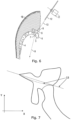
Figure 6 is a schematically illustration of an embodiment of removal of the spinal column according to a further embodiment of the invention where the half-carcass is suspended in a vertical orientation, -
Figure 7 is a schematically illustration of two different cutting paths, and -
Figure 8 is a schematically illustration of a cutting path in section of a haf-carcass not comprising ribs not belonging to the invention. -
Figure 1 shows a cross section of the carcass of a slaughtered animal. A dotted line II-II indicates themedial plane 2 along which the carcass is to be cut to provide two half-carcasses spinal column 3 with thespinal canal 5 andribs 4 connected to the spinal column are seen. -
Figure 2 shows the half-carcass 1A supported by aconveyor 8. Ascanner 10 projects light towards a zone of the ventral side of the half-carcass 1A, the zone including at least theconcavity 7 defined in relation to joints between rib heads and thespinal column 3 of the half-carcass 1A. Light is reflected from the carcass and is received by a light receiver such as a camera in thescanner 10, and image data from the camera is processed to identify and locate theconcavity 7. - It is noted that the half-
carcass carcass fig. 8 . - Reference is made to
figure 3, 4 and5A and 5B. As shown in these figures, the method of removing, at least partly, the spinal column from a half-carcass median plane 2 of the slaughtered animal thereby providing amedian cut surface 6 of the half-carcass (1A, 1B), may comprise the steps of locating, on the ventral side of the half-carcass anatomical structure 7 defined in relation to joints between rib heads and thespinal column 3 of the half-carcass geometrical feature 15 of e.g. themedian cut surface 6 and/or of the ventral side of the half-carcass - It is noted that "locating" and "determining" both refers to a situation where an image is obtained of the half-
carcass - The characteristic
geometrical feature 15 may as indicated infigures 3 and 4 comprise a position (fig. 4 ) on and/or a spatial orientation (fig. 3 ) of at least a part of the spinal column. - Based on the characteristic
geometrical feature 15 is located and theanatomical structure 7 is located, the cutting along a cuttingpath 13 is defined in relation to those two features said anatomical structure (7) so as to, at least partly, remove the spinal column from the half-carcass - As shown in
fig. 3 and 4 , the cuttingpath 13 passes through a position being offset a predetermined first offset to the locatedanatomical feature 7 and a position in the half-carcass geometrical feature 15. - The offset may typically be predetermined by an operator operating the cutting equipment input a value for the first and the second offset to cutting device (controlled by a computer). The operator evaluates the cut provided and if the initial input offset values provides a cut which is not the operator's satisfaction due to e.g. too much removal of meat or to little removal of spinal column the operator adjust the first and/or second offset. This procedure is continued until the operator is satisfied with the cutting. After that, the offsets typically remains unchanged until an operator finds reason to change one or more of the offsets.
- While the offsets typically are predetermined by an operator, the offsets may alternatively be predetermined in an automated manner, where vision equipment evaluates the cutting and changes the offsets until a desired result is obtained.
- As shown in
fig.s 35A , the characteristic geometrical feature may be a spatial orientation. Infigure 3 , the characteristicgeometrical feature 15 is the angle of the tangent in a point on the spinal column which in the example offig. 3 is shown to be 65.5° and the predetermined offset angle is 15.7° (as indicated infig. 3 , reference III). Thus, the cutting is made so that the cutting path is angled 65.5°+15.7° to the tangent in the point considered. - As shown in
fig. 5A and 5B , the characteristicgeometrical feature 15 is the spatial orientation of themedian cut surface 6, and the second offset is a predetermined angle V with the characteristic geometrical feature. - Reference is made to
fig. 4 . In this embodiment, the characteristicgeometrical feature 15 is a position and the first and second offset is a predetermined orientated distance from the characteristicgeometrical feature 15. The characteristicgeometrical feature 15 is typically selected as a position on the spinal column which is easy recognisable in an image and may e.g. be selected as the point positioned a certain distance from e.g. the upper most position of thespinal column 16. Similarly, the location of the anatomical structure may be carried out in a similar manner. - The
anatomical structure 7 is selected as a concavity defined in relation to the joint between rib heads and thoracic vertebrae, top of rib heads, or a concavity below therib head 17. - The characteristic
geometrical feature 15 is selected as spinous process, the spatial orientation of themedian cut surface 6, spinal canal, the upper most position of thespinal column 16, or the tangent to the surface between the upper most position of thespinal column 16 and theanatomical structure 7. - Reference is made to
figure 5A and 5b . As disclosed herein, a cutting path is determined to optimally remove the spinal column, i.e. without removing too much meat and not leaving too much bone.Figure 5A shows a half vertebra of thespinal column 3 and arib 4 in the half-carcass. It is desired to cut along a plane cutting path defined by the line L2 intersecting theconcavity 7 such as its "deepest" point and the point (XB, YB) near the tip of the spinous process of the vertebra. The point (XA, YA) is identified and located optically by devices/means corresponding to theoptical scanner 10 used to locate theconcavity 7 whereby the cutting path is determined, or the cuttingpath 13 is determined based on the spatial orientation of themedian cut surface 6, which is determined optically. The cuttingpath 13 is then determined as the plane intersecting theconcavity 7 and forming a predetermined angle V with themedian cut surface 6. Although the cuttingpath 13 herein is disclosed as a straight line, the cutting path may be curved. For instance, in cases where curved saw is used, the cutting path may reflect the shape of the knife. - The predetermined angle V of the cutting
path 13 relative to themedian cut surface 6 depends on e.g. the species of the animal and/or the size of the animal and/or the position along the spinal column. The location and angle of the cuttingpath 13 may be further adjusted manually or adaptively.Figure 2 shows the cuttingpath 13A as determined automatically, andalternative cutting paths -
Figure 5B illustrates steps in the process of determining the cuttingpath 13. Themedian cut surface 6 as represented by the line L1 is defined by Y = α1x + β1 which is preferably determined using optical locator/means. The coordinates (XA, YA) of theconcavity 7 are determined as mentioned above, preferably by optical locator/means. The predetermined angle V is retrieved from a storage, and the cuttingpath 13 as represented by the line L2 defined by Y = α2x + β2 is determined by a controller (not shown) based on the values of XA, YA, α1 and V. The predetermined angle (V) of the cutting path typically depends on the species of the animal and/or the size of the animal and/or the position along thespinal column 3. In a further embodiment, an offset may be added to one or both of the coordinates (XA, YA), for instance to alter the orientation of the line L2 if so desired. Infig. 5A the notations "f(V,α1)" and "g(XA, YA)" are used to reference two functional relations, typically being mathematical relations, "f" and "g". - Cutting can be performed by using cutting device known in the art, such as a
circular cutting blade 12 driven by amotor 11, areciprocating cutting blade 12 driven by amotor 11, anendless cutting blade 12 driven by amotor 11 or a water-jet cutting device.. Themotor 11 with the cutting blade 12 (or water-jet cutting device) is moved by a robotic arm (not shown) controlled by the controller so that the cutting blade follows the determined cuttingpath 13 to eventually remove the spinal column at least partly. - The interaction of the cutting blade with the half-carcass may cause the half-carcass to move on the conveyor which may cause the cutting blade to follow a wrong cutting path. In order to ensure that the cutting blade follows the desired cutting path it is advantageous to have mechanical stabilisers/means for stabilising the position of the half-carcass on the conveyor against undesired movements on the conveyer.
- It is noted that the present invention also includes embodiments in which the half-carcass is not moved during cutting, in which case the cutting blade is moved along the longitudinal direction of the half-carcass. Further, the cutting may be performed from ventral side, towards the ventral side or combinations thereof.
- As shown in
fig. 7 the actual provided cuttingpath 13 may depend on the cutting device used. Thestraight line 13 indicates a cut provided with e.g. a cutting blade formed as flat disc thereby providing a straight cut. Thecurved line 13 illustrates a cut provided with a curved cutting blade e.g. with a band saw. - Reference is made to
fig. 8 schematically illustration of a cutting path in section of a half-carcass carcass fig. 8 , three different options for a characteristicgeometrical feature 15 are illustrated, which may be combined or used alone. - In such embodiments, the method preferably includes locating, on the ventral side of the half-
carcass anatomical structure 17 defined in relation in relation to the concavity (17 infig. 8 ) between thespinal column 3 and thetransverse process 18. - Further, the method comprising determining a characteristic
geometrical feature 15 of themedian cut surface 6 and/or of the ventral side of the half-carcass geometrical feature 15 comprising a position on and/or a spatial orientation of at least a part of the spinal column - As an example, a position could be the edge indicated by a circle in
fig. 8 and spatial orientation could be the orientation of themedian cut surface 6 to e.g. horizontal (infigure 8 angle indicated relatively to horizontal) and/or the orientation of the edge, the position and/or orientation (e.g. typically relatively to horizontal or in relation to the coordinate system X-Y which may be the same) of a flat part of thetransverse process 18. When the position of the flat part of the transverse process is used, typically a midpoint (as seen in the cross sectional view offig. 8 ) of the flat part is taken as the position. - Still further, the method comprising cutting along a cutting
path 13, the cutting path being defined in relation to saidanatomical structure 17 and said characteristicgeometrical feature 15 of themedian cut surface 6 and/or of the ventral side of the half-carcass, so as to remove, at least partly, the spinal column from the half-carcass - The invention can be implemented by use of/means of hardware, software, firmware or any combination of these. The invention or some of the features thereof can also be implemented as software running on one or more data processors and/or digital signal processors.
- As presented herein, many of the embodiments of the invention resides in locating an anatomical structure and determining a characteristic geometrical feature by use of imaging. Preferably, the imaging is based on electromagnetic radiation which may be characterised as making use of reflection of electromagnetic radiation or transmission of electromagnetic radiation.
-
- 1. In one embodiment laser light (or other light source) is directed towards the half-carcass. One or more cameras are used in a triangulation to obtain an image. The half-carcass can be moved and/or the camera as well as the light source can be moved in order to obtain an image.
- 2. In a further embodiment, stereo-vision is applied. In such embodiments, two cameras are used, in which a calibration of the mutual positioning of the cameras is carried out prior to use. An image is obtained by each camera of the same object and by combining the images information about the depth (distance from camera) can be provided.
- 3. In yet a further embodiment, the so-called time-of-flight method is applied. The time-of-flight method may be implemented in different manner and comprises on an overall level measuring the time spend for the light to travel from the light source, to the half-carcass and to a light receiver, typically placed at the light source. Thereby, the distance from the light source to the position where the light "hits" the half-carcass can be determined. In order to increase the precision, phase shift technologies (or similar) may be implemented. The time-of-flight method may be implemented both with and without measurements of the light intensity.
- 4. In yet a further embodiment, so-called structural light is applied. The structural light is characterised by a light source emitting a light pattern (often infra-red). A camera makes an image of the reflected light pattern. By use of image processing the light pattern can be identified in the image. The size of individual elements in the pattern provides the distance to the object reflecting the elements in the pattern. A calibration is performed between the light source and the camera. Advantageously, this approach may be supplemented by providing an image without a light pattern so this image may be combined with the image obtained by the light pattern in order to get both depth and light intensity measurements.
- 1. In one embodiment, x-ray radiation is applied. An x-ray source transmit x-ray and a detector is arranged to detect x-rays transmitted through the half-carcass. The amount of x-rays detected is used to provide a 3D image of the half-carcass; in order to obtain the 3D image, a number of x-ray sources are used, the half-carcass is moved during radiation and/or the x-ray source(s) are moved. The use of x-ray can further provide information as to the thickness of bones and position thereof.
- The individual elements of an embodiment of the invention may be physically, functionally and logically implemented in any suitable way such as in a single unit, in a plurality of units or as part of separate functional units. The invention may be implemented in a single unit, or be both physically and functionally distributed between different units and processors.
- Although the present invention has been described in connection with the specified embodiments, it should not be construed as being in any way limited to the presented examples. The scope of the present invention is to be interpreted in the light of the accompanying claim set. In the context of the claims, the terms "comprising" or "comprises" do not exclude other possible elements or steps. Also, the mentioning of references such as "a" or "an" etc. should not be construed as excluding a plurality. The use of reference signs in the claims with respect to elements indicated in the figures shall also not be construed as limiting the scope of the invention.
-
- 1
- carcass
- 2
- median plane
- 3
- spinal column
- 4
- rib
- 5
- spinal canal
- 6
- median cut surface
- 7
- anatomical structure such as a concavity defined in relation to joint between rib heads and thoracic vertebrae
- 8
- conveyor
- 9
- line of sight
- 10
- optical scanner
- 11
- motor of cutting device
- 12
- knife of cutting device
- 13
- cutting path
- 15
- characteristic geometrical feature
- 16
- the upper most position of the spinal column,
- 17
- anatomical structure such as a concavity below the rib head
- 18
- transverse process
- 19
- meat tissue
Claims (6)
- A method of removing, at least partly, the spinal column from a half-carcass (1A, 1B) of a slaughtered animal that has been cut substantially along the median plane (2) of the slaughtered animal thereby providing a median cut surface (6) of the half-carcass (1A, 1B), the method comprising- locating, on the ventral side of the half-carcass (1A, 1B), an anatomical structure (7, 17) defined in relation to joints between rib heads and the spinal column (3) of the half-carcass (1A, 1B) and/or in relation to the concavity between the spinal column and the transverse process (18), wherein the step of locating the anatomical structure is done using optical locator providing data on a zone of the half-carcass, preferably including at least the concavity (7, 17);- determining a characteristic geometrical feature (15) of the median cut surface (6) and/or of the ventral side of the half-carcass (1A, 1B), wherein the characteristic geometrical feature (15) is determined using optical locator; the characteristic geometrical feature (15) comprising:o a position on and/or a spatial orientation of at least a part of the exposed rib (4) or spinal column (3) or transverse process (18), and- cutting along a cutting path (13), the cutting path being defined in relation to said anatomical structure (7, 17) and said characteristic geometrical feature (15) of the median cut surface (6) and/or of the ventral side of the half-carcass, so as to remove, at least partly, the spinal column from the half-carcass (1A, 1B), wherein the cutting path (13) passes through a position being offset a predetermined first offset to the located anatomical feature (7, 17) and a position in the half-carcass (1A, 1B) being offset a predetermined second offset from the characteristic geometrical feature (15),wherein the characteristic geometrical feature is a position and wherein the second offset is a predetermined orientated distance from the characteristic geometrical feature (15), andwherein the anatomical structure (7, 17) is- a concavity defined in relation to the joint between rib heads and thoracic vertebrae,- top of rib heads, or- a concavity below the rib head (17); andwherein the characteristic geometrical feature (15) is:- spinous process,- the spatial orientation of the median cut surface (6),- spinal canal (5),- the upper most position of the spinal column (16), or- the tangent to the surface between the upper most position of the spinal column (16) and the anatomical structure (7, 17).
- The method according to any of the preceding claims, comprising- moving the half-carcass, while supported by a conveyor, along a longitudinal direction of the spinal column (3),- illuminating the ventral side of the moving half-carcass, and- obtaining image data on the zone of the half-carcass, preferably including at least the concavity (7).
- A method according to claim 2, wherein- illuminating the ventral side of the half-carcass (1A, 1B) includes projecting a beam of light defining a plane of light transverse to the direction of movement, and- receiving projected light reflected from the half-carcass (1A, 1B) with a camera situated outside the plane of light to obtain profile information on the zone of the half-carcass, preferably including at least the concavity.
- The method according to any of the preceding claims, wherein the half-carcass is arranged on a conveyor and wherein the position of the half-carcass on the conveyor is stabilized.
- The method according to any one of claims 2-4, wherein the half-carcass is arranged suspended in an orientation, the method further comprising- illuminating the ventral side of the half-carcass (1A, 1B) by projecting a beam of light defining a plane of light transverse to the longitudinal direction of the spinal column, and- receiving projected light reflected from the half-carcass (1A, 1B) with a camera situated outside the plane of light to obtain profile information on the zone of the half-carcass including at least the concavity.
- The method according to any of the preceding claims, wherein the half-carcass is arranged on a conveyer, said conveyer comprising an encoder providing data on movements of the conveyer and thereby the half-carcass.
Applications Claiming Priority (3)
| Application Number | Priority Date | Filing Date | Title |
|---|---|---|---|
| DK201570356A DK178447B1 (en) | 2015-06-10 | 2015-06-10 | Removing the spinal column from a half-carcass of a slaughtered animal |
| US14/737,312 US9198441B1 (en) | 2015-06-10 | 2015-06-11 | Removing the spinal column from a half-carcass of a slaughtered animal |
| PCT/EP2016/063363 WO2016198646A1 (en) | 2015-06-10 | 2016-06-10 | Removing the spinal column from a half-carcass of a slaughtered animal |
Publications (3)
| Publication Number | Publication Date |
|---|---|
| EP3307073A1 EP3307073A1 (en) | 2018-04-18 |
| EP3307073B1 EP3307073B1 (en) | 2019-04-03 |
| EP3307073B2 true EP3307073B2 (en) | 2024-09-04 |
Family
ID=54609049
Family Applications (1)
| Application Number | Title | Priority Date | Filing Date |
|---|---|---|---|
| EP16728322.5A Active EP3307073B2 (en) | 2015-06-10 | 2016-06-10 | Removing the spinal column from a half-carcass of a slaughtered animal |
Country Status (6)
| Country | Link |
|---|---|
| US (1) | US9198441B1 (en) |
| EP (1) | EP3307073B2 (en) |
| AU (1) | AU2016275699B2 (en) |
| DK (1) | DK178447B1 (en) |
| ES (1) | ES2729072T5 (en) |
| WO (1) | WO2016198646A1 (en) |
Families Citing this family (2)
| Publication number | Priority date | Publication date | Assignee | Title |
|---|---|---|---|---|
| WO2023217953A1 (en) | 2022-05-12 | 2023-11-16 | Marel Red Meat B.V. | Spine processing device |
| EP4541197A1 (en) * | 2023-10-20 | 2025-04-23 | Ihfood A/S | A system and a computer implemented method of removing, at least partly, a spinal column |
Citations (2)
| Publication number | Priority date | Publication date | Assignee | Title |
|---|---|---|---|---|
| WO2003032739A1 (en) † | 2001-10-16 | 2003-04-24 | Slagteriernes Forskningsinstitut | Apparatus and method for cutting middles |
| US7404759B2 (en) † | 2004-04-16 | 2008-07-29 | Meat Technology R & D Partnership | Spinal column removing method and spinal column removing apparatus |
Family Cites Families (14)
| Publication number | Priority date | Publication date | Assignee | Title |
|---|---|---|---|---|
| US5295896A (en) * | 1992-11-10 | 1994-03-22 | Petersen Ronald A | Bone-cutting meat-recovering unit |
| GB9608376D0 (en) * | 1996-04-23 | 1996-06-26 | Commission Meat & Livestock | Spinal column separation |
| DE19837806C1 (en) | 1998-08-20 | 2000-01-20 | Csb Syst Software Entwicklung | Carcass meat quality control by photogrammetric evaluation of defined standard dimensions |
| DE19936032C1 (en) | 1999-07-30 | 2000-07-13 | Csb Syst Software Entwicklung | Image processing determines the quality of meat within a pig cadaver by calculation of lean meat content between fixed points |
| AU774953B2 (en) | 1999-08-27 | 2004-07-15 | K.J. Maskinfabriken A/S | Arrangement for laying-down half carcasses, and based automatic cutting-up system in connection therewith |
| US8485871B2 (en) * | 2005-09-30 | 2013-07-16 | Cargill, Incorporated | Meat fabrication system and method |
| EP2022334A1 (en) * | 2006-03-13 | 2009-02-11 | Mayekawa Mfg. Co., Ltd. | Method and equipment for removing backbone of carcass |
| US7892076B2 (en) * | 2006-05-22 | 2011-02-22 | Swift & Company | Multibar apparatus and method for electrically stimulating a carcass |
| US7635294B2 (en) * | 2006-07-28 | 2009-12-22 | Tyson Foods, Inc. | Method and apparatus to load and remove bones from primals |
| US7476166B2 (en) * | 2006-10-19 | 2009-01-13 | David Yearick | Kango game |
| US8444461B2 (en) | 2008-10-29 | 2013-05-21 | Georgia Tech Research Corporation | Systems and methods for the detection of anatomical structures and positions thereof |
| AU2010232016B2 (en) | 2009-04-03 | 2015-05-07 | Robotic Technologies Limited | Carcass cutting methods and apparatus |
| DK2566339T3 (en) * | 2010-05-07 | 2017-04-24 | Humboldt Bv | Separation of the spine from the middle part of a carcass |
| DK2532246T3 (en) | 2010-10-27 | 2015-10-05 | Maekawa Seisakusho Kk | Deboning and deboning the meat with bone using X-rays |
-
2015
- 2015-06-10 DK DK201570356A patent/DK178447B1/en active
- 2015-06-11 US US14/737,312 patent/US9198441B1/en active Active
-
2016
- 2016-06-10 EP EP16728322.5A patent/EP3307073B2/en active Active
- 2016-06-10 ES ES16728322T patent/ES2729072T5/en active Active
- 2016-06-10 AU AU2016275699A patent/AU2016275699B2/en active Active
- 2016-06-10 WO PCT/EP2016/063363 patent/WO2016198646A1/en not_active Ceased
Patent Citations (2)
| Publication number | Priority date | Publication date | Assignee | Title |
|---|---|---|---|---|
| WO2003032739A1 (en) † | 2001-10-16 | 2003-04-24 | Slagteriernes Forskningsinstitut | Apparatus and method for cutting middles |
| US7404759B2 (en) † | 2004-04-16 | 2008-07-29 | Meat Technology R & D Partnership | Spinal column removing method and spinal column removing apparatus |
Also Published As
| Publication number | Publication date |
|---|---|
| AU2016275699B2 (en) | 2021-06-24 |
| ES2729072T5 (en) | 2025-02-05 |
| ES2729072T3 (en) | 2019-10-30 |
| EP3307073B1 (en) | 2019-04-03 |
| US9198441B1 (en) | 2015-12-01 |
| AU2016275699A1 (en) | 2018-01-18 |
| EP3307073A1 (en) | 2018-04-18 |
| DK178447B1 (en) | 2016-02-29 |
| WO2016198646A1 (en) | 2016-12-15 |
Similar Documents
| Publication | Publication Date | Title |
|---|---|---|
| DK2531038T3 (en) | A food processing apparatus for recording and cutting tough tissues from the food items | |
| CN109788766B (en) | Cutting/segmentation using a combination of X-ray and optical scanning | |
| CN113906469B (en) | Determine the thickness profile of the work product | |
| JP2007522948A (en) | Method and apparatus for cutting food or similar articles into sections | |
| DK2566339T3 (en) | Separation of the spine from the middle part of a carcass | |
| EP3307073B2 (en) | Removing the spinal column from a half-carcass of a slaughtered animal | |
| EP2946667B1 (en) | X-ray imaging apparatus for determining a cutting path of a carcass and corresponding method | |
| US9285666B2 (en) | Object guide system | |
| CN109068666B (en) | System and method for measuring shoulder joint position of carcass parts of slaughtered poultry | |
| US10845615B2 (en) | Method of generating a three dimensional surface profile of a food object | |
| NL1021928C2 (en) | Slaughterhouse device, determines desired carcass processing position by generating linear image of carcass and processing image to detect carcass anatomy irregularity for use as reference | |
| WO2024227858A1 (en) | Apparatus and method for cutting middle pieces of a half carcass | |
| AU2022490923A1 (en) | A method for selecting targets for lidar in automated mode. | |
| CA3130916A1 (en) | Image processing device, image processing program, and image processing method | |
| WO2012011809A1 (en) | Camera and method for forming a recording of an image of at least a part of an object |
Legal Events
| Date | Code | Title | Description |
|---|---|---|---|
| STAA | Information on the status of an ep patent application or granted ep patent |
Free format text: STATUS: THE INTERNATIONAL PUBLICATION HAS BEEN MADE |
|
| PUAI | Public reference made under article 153(3) epc to a published international application that has entered the european phase |
Free format text: ORIGINAL CODE: 0009012 |
|
| STAA | Information on the status of an ep patent application or granted ep patent |
Free format text: STATUS: REQUEST FOR EXAMINATION WAS MADE |
|
| 17P | Request for examination filed |
Effective date: 20180105 |
|
| AK | Designated contracting states |
Kind code of ref document: A1 Designated state(s): AL AT BE BG CH CY CZ DE DK EE ES FI FR GB GR HR HU IE IS IT LI LT LU LV MC MK MT NL NO PL PT RO RS SE SI SK SM TR |
|
| AX | Request for extension of the european patent |
Extension state: BA ME |
|
| DAV | Request for validation of the european patent (deleted) | ||
| DAX | Request for extension of the european patent (deleted) | ||
| GRAP | Despatch of communication of intention to grant a patent |
Free format text: ORIGINAL CODE: EPIDOSNIGR1 |
|
| STAA | Information on the status of an ep patent application or granted ep patent |
Free format text: STATUS: GRANT OF PATENT IS INTENDED |
|
| INTG | Intention to grant announced |
Effective date: 20181010 |
|
| GRAS | Grant fee paid |
Free format text: ORIGINAL CODE: EPIDOSNIGR3 |
|
| GRAA | (expected) grant |
Free format text: ORIGINAL CODE: 0009210 |
|
| STAA | Information on the status of an ep patent application or granted ep patent |
Free format text: STATUS: THE PATENT HAS BEEN GRANTED |
|
| RAP1 | Party data changed (applicant data changed or rights of an application transferred) |
Owner name: IHFOOD A/S Owner name: SFK LEBLANC A/S |
|
| AK | Designated contracting states |
Kind code of ref document: B1 Designated state(s): AL AT BE BG CH CY CZ DE DK EE ES FI FR GB GR HR HU IE IS IT LI LT LU LV MC MK MT NL NO PL PT RO RS SE SI SK SM TR |
|
| REG | Reference to a national code |
Ref country code: GB Ref legal event code: FG4D |
|
| REG | Reference to a national code |
Ref country code: CH Ref legal event code: EP Ref country code: AT Ref legal event code: REF Ref document number: 1114618 Country of ref document: AT Kind code of ref document: T Effective date: 20190415 |
|
| REG | Reference to a national code |
Ref country code: DE Ref legal event code: R096 Ref document number: 602016011939 Country of ref document: DE |
|
| REG | Reference to a national code |
Ref country code: IE Ref legal event code: FG4D |
|
| REG | Reference to a national code |
Ref country code: NL Ref legal event code: MP Effective date: 20190403 |
|
| REG | Reference to a national code |
Ref country code: LT Ref legal event code: MG4D |
|
| REG | Reference to a national code |
Ref country code: AT Ref legal event code: MK05 Ref document number: 1114618 Country of ref document: AT Kind code of ref document: T Effective date: 20190403 |
|
| PG25 | Lapsed in a contracting state [announced via postgrant information from national office to epo] |
Ref country code: NL Free format text: LAPSE BECAUSE OF FAILURE TO SUBMIT A TRANSLATION OF THE DESCRIPTION OR TO PAY THE FEE WITHIN THE PRESCRIBED TIME-LIMIT Effective date: 20190403 |
|
| REG | Reference to a national code |
Ref country code: ES Ref legal event code: FG2A Ref document number: 2729072 Country of ref document: ES Kind code of ref document: T3 Effective date: 20191030 |
|
| PG25 | Lapsed in a contracting state [announced via postgrant information from national office to epo] |
Ref country code: FI Free format text: LAPSE BECAUSE OF FAILURE TO SUBMIT A TRANSLATION OF THE DESCRIPTION OR TO PAY THE FEE WITHIN THE PRESCRIBED TIME-LIMIT Effective date: 20190403 Ref country code: NO Free format text: LAPSE BECAUSE OF FAILURE TO SUBMIT A TRANSLATION OF THE DESCRIPTION OR TO PAY THE FEE WITHIN THE PRESCRIBED TIME-LIMIT Effective date: 20190703 Ref country code: HR Free format text: LAPSE BECAUSE OF FAILURE TO SUBMIT A TRANSLATION OF THE DESCRIPTION OR TO PAY THE FEE WITHIN THE PRESCRIBED TIME-LIMIT Effective date: 20190403 Ref country code: LT Free format text: LAPSE BECAUSE OF FAILURE TO SUBMIT A TRANSLATION OF THE DESCRIPTION OR TO PAY THE FEE WITHIN THE PRESCRIBED TIME-LIMIT Effective date: 20190403 Ref country code: CZ Free format text: LAPSE BECAUSE OF FAILURE TO SUBMIT A TRANSLATION OF THE DESCRIPTION OR TO PAY THE FEE WITHIN THE PRESCRIBED TIME-LIMIT Effective date: 20190403 Ref country code: AL Free format text: LAPSE BECAUSE OF FAILURE TO SUBMIT A TRANSLATION OF THE DESCRIPTION OR TO PAY THE FEE WITHIN THE PRESCRIBED TIME-LIMIT Effective date: 20190403 Ref country code: PT Free format text: LAPSE BECAUSE OF FAILURE TO SUBMIT A TRANSLATION OF THE DESCRIPTION OR TO PAY THE FEE WITHIN THE PRESCRIBED TIME-LIMIT Effective date: 20190803 Ref country code: SE Free format text: LAPSE BECAUSE OF FAILURE TO SUBMIT A TRANSLATION OF THE DESCRIPTION OR TO PAY THE FEE WITHIN THE PRESCRIBED TIME-LIMIT Effective date: 20190403 |
|
| PG25 | Lapsed in a contracting state [announced via postgrant information from national office to epo] |
Ref country code: GR Free format text: LAPSE BECAUSE OF FAILURE TO SUBMIT A TRANSLATION OF THE DESCRIPTION OR TO PAY THE FEE WITHIN THE PRESCRIBED TIME-LIMIT Effective date: 20190704 Ref country code: PL Free format text: LAPSE BECAUSE OF FAILURE TO SUBMIT A TRANSLATION OF THE DESCRIPTION OR TO PAY THE FEE WITHIN THE PRESCRIBED TIME-LIMIT Effective date: 20190403 Ref country code: RS Free format text: LAPSE BECAUSE OF FAILURE TO SUBMIT A TRANSLATION OF THE DESCRIPTION OR TO PAY THE FEE WITHIN THE PRESCRIBED TIME-LIMIT Effective date: 20190403 Ref country code: LV Free format text: LAPSE BECAUSE OF FAILURE TO SUBMIT A TRANSLATION OF THE DESCRIPTION OR TO PAY THE FEE WITHIN THE PRESCRIBED TIME-LIMIT Effective date: 20190403 Ref country code: BG Free format text: LAPSE BECAUSE OF FAILURE TO SUBMIT A TRANSLATION OF THE DESCRIPTION OR TO PAY THE FEE WITHIN THE PRESCRIBED TIME-LIMIT Effective date: 20190703 |
|
| PG25 | Lapsed in a contracting state [announced via postgrant information from national office to epo] |
Ref country code: AT Free format text: LAPSE BECAUSE OF FAILURE TO SUBMIT A TRANSLATION OF THE DESCRIPTION OR TO PAY THE FEE WITHIN THE PRESCRIBED TIME-LIMIT Effective date: 20190403 Ref country code: IS Free format text: LAPSE BECAUSE OF FAILURE TO SUBMIT A TRANSLATION OF THE DESCRIPTION OR TO PAY THE FEE WITHIN THE PRESCRIBED TIME-LIMIT Effective date: 20190803 |
|
| REG | Reference to a national code |
Ref country code: DE Ref legal event code: R026 Ref document number: 602016011939 Country of ref document: DE |
|
| PLBI | Opposition filed |
Free format text: ORIGINAL CODE: 0009260 |
|
| PLAX | Notice of opposition and request to file observation + time limit sent |
Free format text: ORIGINAL CODE: EPIDOSNOBS2 |
|
| PG25 | Lapsed in a contracting state [announced via postgrant information from national office to epo] |
Ref country code: RO Free format text: LAPSE BECAUSE OF FAILURE TO SUBMIT A TRANSLATION OF THE DESCRIPTION OR TO PAY THE FEE WITHIN THE PRESCRIBED TIME-LIMIT Effective date: 20190403 Ref country code: SK Free format text: LAPSE BECAUSE OF FAILURE TO SUBMIT A TRANSLATION OF THE DESCRIPTION OR TO PAY THE FEE WITHIN THE PRESCRIBED TIME-LIMIT Effective date: 20190403 Ref country code: MC Free format text: LAPSE BECAUSE OF FAILURE TO SUBMIT A TRANSLATION OF THE DESCRIPTION OR TO PAY THE FEE WITHIN THE PRESCRIBED TIME-LIMIT Effective date: 20190403 Ref country code: EE Free format text: LAPSE BECAUSE OF FAILURE TO SUBMIT A TRANSLATION OF THE DESCRIPTION OR TO PAY THE FEE WITHIN THE PRESCRIBED TIME-LIMIT Effective date: 20190403 Ref country code: DK Free format text: LAPSE BECAUSE OF FAILURE TO SUBMIT A TRANSLATION OF THE DESCRIPTION OR TO PAY THE FEE WITHIN THE PRESCRIBED TIME-LIMIT Effective date: 20190403 |
|
| REG | Reference to a national code |
Ref country code: CH Ref legal event code: PL |
|
| PLAN | Information deleted related to communication of a notice of opposition and request to file observations + time limit |
Free format text: ORIGINAL CODE: EPIDOSDOBS2 |
|
| 26 | Opposition filed |
Opponent name: MAREL RED MEAT SLAUGHTERING B.V. Effective date: 20200103 |
|
| PLAX | Notice of opposition and request to file observation + time limit sent |
Free format text: ORIGINAL CODE: EPIDOSNOBS2 |
|
| PG25 | Lapsed in a contracting state [announced via postgrant information from national office to epo] |
Ref country code: IT Free format text: LAPSE BECAUSE OF FAILURE TO SUBMIT A TRANSLATION OF THE DESCRIPTION OR TO PAY THE FEE WITHIN THE PRESCRIBED TIME-LIMIT Effective date: 20190403 Ref country code: SM Free format text: LAPSE BECAUSE OF FAILURE TO SUBMIT A TRANSLATION OF THE DESCRIPTION OR TO PAY THE FEE WITHIN THE PRESCRIBED TIME-LIMIT Effective date: 20190403 |
|
| REG | Reference to a national code |
Ref country code: BE Ref legal event code: MM Effective date: 20190630 |
|
| PG25 | Lapsed in a contracting state [announced via postgrant information from national office to epo] |
Ref country code: TR Free format text: LAPSE BECAUSE OF FAILURE TO SUBMIT A TRANSLATION OF THE DESCRIPTION OR TO PAY THE FEE WITHIN THE PRESCRIBED TIME-LIMIT Effective date: 20190403 |
|
| PG25 | Lapsed in a contracting state [announced via postgrant information from national office to epo] |
Ref country code: IE Free format text: LAPSE BECAUSE OF NON-PAYMENT OF DUE FEES Effective date: 20190610 |
|
| PG25 | Lapsed in a contracting state [announced via postgrant information from national office to epo] |
Ref country code: LU Free format text: LAPSE BECAUSE OF NON-PAYMENT OF DUE FEES Effective date: 20190610 Ref country code: BE Free format text: LAPSE BECAUSE OF NON-PAYMENT OF DUE FEES Effective date: 20190630 Ref country code: SI Free format text: LAPSE BECAUSE OF FAILURE TO SUBMIT A TRANSLATION OF THE DESCRIPTION OR TO PAY THE FEE WITHIN THE PRESCRIBED TIME-LIMIT Effective date: 20190403 Ref country code: LI Free format text: LAPSE BECAUSE OF NON-PAYMENT OF DUE FEES Effective date: 20190630 Ref country code: CH Free format text: LAPSE BECAUSE OF NON-PAYMENT OF DUE FEES Effective date: 20190630 |
|
| PLBB | Reply of patent proprietor to notice(s) of opposition received |
Free format text: ORIGINAL CODE: EPIDOSNOBS3 |
|
| PG25 | Lapsed in a contracting state [announced via postgrant information from national office to epo] |
Ref country code: CY Free format text: LAPSE BECAUSE OF FAILURE TO SUBMIT A TRANSLATION OF THE DESCRIPTION OR TO PAY THE FEE WITHIN THE PRESCRIBED TIME-LIMIT Effective date: 20190403 |
|
| PG25 | Lapsed in a contracting state [announced via postgrant information from national office to epo] |
Ref country code: HU Free format text: LAPSE BECAUSE OF FAILURE TO SUBMIT A TRANSLATION OF THE DESCRIPTION OR TO PAY THE FEE WITHIN THE PRESCRIBED TIME-LIMIT; INVALID AB INITIO Effective date: 20160610 Ref country code: MT Free format text: LAPSE BECAUSE OF FAILURE TO SUBMIT A TRANSLATION OF THE DESCRIPTION OR TO PAY THE FEE WITHIN THE PRESCRIBED TIME-LIMIT Effective date: 20190403 |
|
| PLAB | Opposition data, opponent's data or that of the opponent's representative modified |
Free format text: ORIGINAL CODE: 0009299OPPO |
|
| R26 | Opposition filed (corrected) |
Opponent name: MAREL RED MEAT B.V. Effective date: 20200103 |
|
| PG25 | Lapsed in a contracting state [announced via postgrant information from national office to epo] |
Ref country code: MK Free format text: LAPSE BECAUSE OF FAILURE TO SUBMIT A TRANSLATION OF THE DESCRIPTION OR TO PAY THE FEE WITHIN THE PRESCRIBED TIME-LIMIT Effective date: 20190403 |
|
| APBM | Appeal reference recorded |
Free format text: ORIGINAL CODE: EPIDOSNREFNO |
|
| APBP | Date of receipt of notice of appeal recorded |
Free format text: ORIGINAL CODE: EPIDOSNNOA2O |
|
| APAH | Appeal reference modified |
Free format text: ORIGINAL CODE: EPIDOSCREFNO |
|
| APBQ | Date of receipt of statement of grounds of appeal recorded |
Free format text: ORIGINAL CODE: EPIDOSNNOA3O |
|
| P01 | Opt-out of the competence of the unified patent court (upc) registered |
Effective date: 20230512 |
|
| APBU | Appeal procedure closed |
Free format text: ORIGINAL CODE: EPIDOSNNOA9O |
|
| PUAH | Patent maintained in amended form |
Free format text: ORIGINAL CODE: 0009272 |
|
| STAA | Information on the status of an ep patent application or granted ep patent |
Free format text: STATUS: PATENT MAINTAINED AS AMENDED |
|
| 27A | Patent maintained in amended form |
Effective date: 20240904 |
|
| AK | Designated contracting states |
Kind code of ref document: B2 Designated state(s): AL AT BE BG CH CY CZ DE DK EE ES FI FR GB GR HR HU IE IS IT LI LT LU LV MC MK MT NL NO PL PT RO RS SE SI SK SM TR |
|
| REG | Reference to a national code |
Ref country code: DE Ref legal event code: R102 Ref document number: 602016011939 Country of ref document: DE |
|
| REG | Reference to a national code |
Ref country code: ES Ref legal event code: DC2A Ref document number: 2729072 Country of ref document: ES Kind code of ref document: T5 Effective date: 20250205 |
|
| PGFP | Annual fee paid to national office [announced via postgrant information from national office to epo] |
Ref country code: DE Payment date: 20250618 Year of fee payment: 10 |
|
| PGFP | Annual fee paid to national office [announced via postgrant information from national office to epo] |
Ref country code: GB Payment date: 20250618 Year of fee payment: 10 |
|
| PGFP | Annual fee paid to national office [announced via postgrant information from national office to epo] |
Ref country code: FR Payment date: 20250625 Year of fee payment: 10 |
|
| PGFP | Annual fee paid to national office [announced via postgrant information from national office to epo] |
Ref country code: ES Payment date: 20250728 Year of fee payment: 10 |