EP3306915B1 - Method and apparatus for controlling image data - Google Patents
Method and apparatus for controlling image data Download PDFInfo
- Publication number
- EP3306915B1 EP3306915B1 EP16803781.0A EP16803781A EP3306915B1 EP 3306915 B1 EP3306915 B1 EP 3306915B1 EP 16803781 A EP16803781 A EP 16803781A EP 3306915 B1 EP3306915 B1 EP 3306915B1
- Authority
- EP
- European Patent Office
- Prior art keywords
- light source
- luminance
- area
- image
- surrounding
- Prior art date
- Legal status (The legal status is an assumption and is not a legal conclusion. Google has not performed a legal analysis and makes no representation as to the accuracy of the status listed.)
- Active
Links
Images


Classifications
-
- G—PHYSICS
- G06—COMPUTING OR CALCULATING; COUNTING
- G06T—IMAGE DATA PROCESSING OR GENERATION, IN GENERAL
- G06T5/00—Image enhancement or restoration
- G06T5/90—Dynamic range modification of images or parts thereof
- G06T5/92—Dynamic range modification of images or parts thereof based on global image properties
-
- H—ELECTRICITY
- H04—ELECTRIC COMMUNICATION TECHNIQUE
- H04N—PICTORIAL COMMUNICATION, e.g. TELEVISION
- H04N5/00—Details of television systems
- H04N5/44—Receiver circuitry for the reception of television signals according to analogue transmission standards
- H04N5/57—Control of contrast or brightness
-
- G—PHYSICS
- G06—COMPUTING OR CALCULATING; COUNTING
- G06T—IMAGE DATA PROCESSING OR GENERATION, IN GENERAL
- G06T5/00—Image enhancement or restoration
- G06T5/40—Image enhancement or restoration using histogram techniques
-
- G—PHYSICS
- G06—COMPUTING OR CALCULATING; COUNTING
- G06T—IMAGE DATA PROCESSING OR GENERATION, IN GENERAL
- G06T5/00—Image enhancement or restoration
- G06T5/90—Dynamic range modification of images or parts thereof
- G06T5/94—Dynamic range modification of images or parts thereof based on local image properties, e.g. for local contrast enhancement
-
- G—PHYSICS
- G06—COMPUTING OR CALCULATING; COUNTING
- G06T—IMAGE DATA PROCESSING OR GENERATION, IN GENERAL
- G06T7/00—Image analysis
- G06T7/80—Analysis of captured images to determine intrinsic or extrinsic camera parameters, i.e. camera calibration
-
- H—ELECTRICITY
- H04—ELECTRIC COMMUNICATION TECHNIQUE
- H04N—PICTORIAL COMMUNICATION, e.g. TELEVISION
- H04N25/00—Circuitry of solid-state image sensors [SSIS]; Control thereof
- H04N25/50—Control of the SSIS exposure
- H04N25/57—Control of the dynamic range
-
- H—ELECTRICITY
- H04—ELECTRIC COMMUNICATION TECHNIQUE
- H04N—PICTORIAL COMMUNICATION, e.g. TELEVISION
- H04N9/00—Details of colour television systems
- H04N9/64—Circuits for processing colour signals
-
- G—PHYSICS
- G06—COMPUTING OR CALCULATING; COUNTING
- G06T—IMAGE DATA PROCESSING OR GENERATION, IN GENERAL
- G06T2207/00—Indexing scheme for image analysis or image enhancement
- G06T2207/20—Special algorithmic details
- G06T2207/20172—Image enhancement details
- G06T2207/20208—High dynamic range [HDR] image processing
Definitions
- the present disclosure relates to a method and an apparatus for controlling the luminance of image data.
- the original image data when the peak luminance of original image data is higher than the peak luminance of a display device, the original image data may be converted in accordance with the peak luminance of the display device so that the original image data can be displayed on various display devices having different levels of peak luminance.
- An operation of converting the peak luminance of original image data in accordance with the peak luminance of a display device is called tone mapping.
- a High-Dynamic-Range (HDR) technique is a scheme for generating optimal image data by generating a plurality of image data having different levels of luminance in one scene and by composing the plurality of image data. For example, in one scene including subjects having a wide range of luminance, such as a scene in which the sun in the bright sky coexists with a dark hill in the shadows, images with moderate luminance in each of the respective subjects are selected and composed using the HDR technique, thereby expressing both the bright sky and the dark hill with appropriate luminance in a single image.
- US 2015/070376 A1 discloses a video display device which detects areas of a video signal that represent light emission.
- US 2013/021498 A1 discloses a blurring process that is performed on an addition area including a point light source area detected in an image to be processed so that the nearer to the circumference of the addition area, the higher the luminance value while an addition coefficient is being increased according to a distance from the center.
- one image is displayed differently depending on the peak luminance of a display device.
- the contrast ratio of an image may be reduced to thus cause a significant change in chroma, thus limiting the range in which luminance can be expressed. This may limit the performance of the display device to which the High-Dynamic-Range (HDR) technique is applied.
- HDR High-Dynamic-Range
- the present disclosure provides a method for controlling the luminance of an image, as defined in claim 1.
- the present disclosure provides an apparatus for controlling the luminance of an image, as defined in claim 9.
- first, second, etc. can be used for describing various elements, the structural elements are not restricted by the terms. The terms are used merely for the purpose to distinguish an element from the other elements. For example, a first element could be termed a second element, and similarly, a second element could be also termed a first element without departing from the scope of the present disclosure.
- the term "and/or" includes any and all combinations of one or more associated items.
- the present disclosure aims to control the luminance of an image in view of at least one of the characteristics of an image, the characteristics of a display device for displaying an image, and the characteristics of the environment surrounding a reproduction device.
- the present disclosure determines a light source area and a surrounding area in one image and adjusts the luminance characteristics of the light source area and the surrounding area so as to provide the user with the maximized effect of the light source. For example, by expanding a light source area of an original image and reducing the luminance of a surrounding area of the original image, a light source may be effectively represented in the image.
- the present disclosure illustrates a method for determining a light source area, a method for determining a surrounding area, and a method for determining a factor related to the luminance characteristics of the light source area and the surrounding area and the value of the factor in order to control the luminance characteristics.
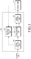
- FIG. 1 is a view illustrating the configuration of an image reproduction apparatus according to an embodiment of the present disclosure.
- content 101 including image data is input to the image reproduction apparatus 100, and the image reproduction apparatus 100 may decode the image data, may determine a light source area and a surrounding area of a light source in each scene of the image data, and may control the luminance of the image data in view of the luminance characteristics of the light source area and the surrounding area, the characteristics of the content and/or the surrounding environment.
- the image data is output to a display unit 111 and is displayed.
- the display unit 111 may be a part of the image reproduction apparatus 100 or may be a separate apparatus connected outside the image reproduction apparatus 111.
- the content 101 includes image data, such as a movie and Video On Demand (VOD), and includes metadata indicating the characteristics of the content.
- image data such as a movie and Video On Demand (VOD)
- VOD Video On Demand
- the solid line indicates the flow of the image data
- the dotted line indicates the flow of the metadata
- a signal analysis unit 103 analyzes the input content 101, distinguishes the image data from the metadata, transmits the image data to a tone-mapping unit 107, and transmits the metadata to a metadata analysis unit 105.
- the metadata analysis unit 105 receives content-related metadata and/or display-related metadata from the signal analysis unit 103.
- the metadata analysis unit 105 may receive display-related metadata from the display unit 111.
- the peak luminance of the display unit 111 is information necessary for tone mapping.
- the metadata analysis unit 105 may request the display unit 111 to receive the display-related metadata including the information on the peak luminance of the display unit and/or other pieces of information.
- the metadata analysis unit 105 receives the received content-related metadata and/or display-related metadata, checks metadata necessary to adjust the luminance of the image data from the received metadata, and transmits the at least one piece of checked metadata to the tone-mapping unit 107.
- the metadata necessary to adjust the luminance of the image data and a description thereof are as follows.
- the metadata (1) to (6) may be identified from the content-related metadata
- the metadata (7) may be identified from the display-related metadata.
- the tone-mapping unit 107 adjusts the luminance value of the image data based on the metadata transmitted from the metadata analysis unit 105 so that the peak luminance value of the content corresponds to a display peak luminance value. In addition, the tone-mapping unit 107 transmits the metadata necessary to adjust the luminance of the image data to an image control unit 109.
- the image control unit 109 detects a light source area and a surrounding area in each scene of the tone-mapped image data and adjusts the luminance of the detected light source area and the detected surrounding area based on the received metadata (that is, the content-related metadata and/or the display-related metadata) or surrounding environment information.
- the surrounding environment information may be received from an ambient sensor (not shown in FIG. 1 for convenience).
- the ambient sensor may detect the surrounding environment information including the ambient luminance of the display unit 111 and may transmit the surrounding environment information to the image control unit 109.
- the metadata have been described as being transmitted from the tone-mapping unit 107, the image control unit 109 may receive the metadata directly from the metadata analysis unit 105.
- the light source area refers to an area recognized as a light source on the screen when a user views the image, which is a set of neighboring pixels having similar luminance values among pixels having a luminance value equal to or greater than a predetermined threshold.
- the internal area connecting the neighboring pixels included in the set may be determined as the light source area.
- the surrounding area refers to an area around the light source that can influence or can be influenced by the luminance of the light source area.
- the operation of the image control unit 109 may be broadly divided into five steps.
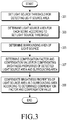
- FIG. 3 is a view illustrating the operation of the image control unit 109 according to an embodiment of the present disclosure.
- step 301 the image control unit 109 sets a light source threshold for detecting a light source area.
- step 303 the image control unit 109 detects a light source area in each scene (that is, frame) according to the set light source threshold.
- step 305 the image control unit 109 determines a surrounding area that can influence or can be influenced by the luminance of the light source area.
- step 307 the image control unit 109 determines a calibration factor and a calibration value for calibrating the luminance characteristics of the detected light source area and the surrounding area.
- step 309 the image control unit 109 corrects the luminance characteristics of the light source area and the surrounding area according to the determined calibration factor and calibration value.
- the light source threshold may be set by various methods, examples of which are illustrated below in (a) to (d).
- step 303 of FIG. 3 the light source area is determined by the following method.
- the image control unit 109 detects pixels on the screen that have luminance values greater than the light source threshold set by the above methods.
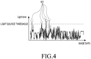
- FIG. 4 is a view illustrating an example of distinguishing a light source pixel in an image when a light source threshold is set according to an embodiment of the present disclosure.
- the light source threshold is set by one of the above methods for setting the light source threshold, light source pixels in which the strength of a light signal is equal to or greater than the light source threshold are identified from among the pixels in the image data for each scene.
- the light source pixels are indicated by reference numeral 401.
- adjacent pixels having similar luminance values within a predetermined range among the detected light source pixels are grouped.
- An internal area connecting the grouped pixels is determined to be one light source area.
- a plurality of light source pixels may be detected, from which at least one or more light source areas may be detected.
- the center point of a light source is set with respect to each detected light source.
- step 303 The details of step 303 may be summarized as follows.
- step 305 of FIG. 3 the surrounding area is determined by the following method.
- the method for determining the surrounding area may be determined as a scale-up type or a window type.
- an area having a size k times that of the light source area based on the center point of the light source may be determined to be the surrounding area.
- the coordinates of a top left point and a bottom right point may be determined, based on the center point of the light source area, to form a rectangular shape.
- the surrounding area may be determined in greater detail using the scale-up type than using the window type. Therefore, the scale-up type may be used to express a detailed image.
- the window type is simpler than the scale-up type in determining the surrounding area, and thus may be used when quick image processing is needed.
- FIG. 5 Examples of designation of a surrounding area using the above methods are illustrated in FIG. 5 .
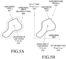
- FIG. 5 is a view illustrating an example of designation of a surrounding area according to an embodiment of the present disclosure.
- step 307 of FIG. 3 the calibration factor and the calibration value for correcting the luminance characteristics of the light source area and the surrounding area are determined by the following method.
- the image control unit 109 may determine a calibration value for at least one of factors that influence the luminance effect of the light source area and the surrounding area based on at least one of the content-related metadata, the display-related metadata, and the surrounding environment information.
- the factors that influence the luminance effect may include (1) the luminance of the light source, (2) the hue of the light source, (3) the saturation of the light source, (4) the size of the light source, (5) the sharpness of the light source, (6) the luminance of the surrounding area, (7) the hue of the surrounding area, and (8) the saturation of the surrounding area, and the image control unit 109 may determine a calibration value for at least one of the factors.
- the method for determining the calibration factor and the calibration value for the image data in the present disclosure may be one of the following examples (1) to (5).
- the luminance effect may be exhibited even when the luminance of an image is calibrated at low calibration intensity.
- the luminance of an image needs to be calibrated at high intensity in order to obtain the effect of luminance calibration. Therefore, if it is possible to detect surrounding environment information, such as information on the ambient luminance of the reproduction apparatus, through an ambient sensor, the image control unit 109 may determine a calibration factor and a calibration value in view of ambient luminance information in addition to the metadata of the content and the metadata of the display unit.
- the calibration factor and the calibration value may be determined by the aforementioned methods. However, when determining the calibration factor and the calibration value in the present disclosure, the calibration factor and the calibration value may be determined such that the size of the light source area is larger than that of the light source area in the original image and such that the luminance of the surrounding area is lower than the original luminance thereof.
- the luminance effect of the light source visually experienced by the user is relative to the luminance of the surrounding area. Therefore, the luminance effect of the light source area may be maximized by adjusting not only the light source area on the screen but also characteristics related to the luminance of the surrounding area. For example, when the luminance of the surrounding area is adjusted to be lower than the actual luminance in the original image, the difference in luminance between the light source area and the surrounding area is increased and the contrast ratio is increased, whereby the user may perceive the light source area to be brighter than it actually is.
- FIG. 6 is a view illustrating an example of a method of adjusting the luminance effects of a light source area and a surrounding area according to an embodiment of the present disclosure.
- the luminance effects are adjusted by calibrating the aforementioned factors that influence the luminance effect, (4) the size of the light source, (6) the luminance of the surrounding area, and (5) the sharpness of the light source.
- the size of a calibrated light source area 602 is increased so as to be greater 605 than the size of the light source area 601 in the original image and the luminance 608 of calibrated surrounding areas is reduced to be lower than the luminance 607 of the surrounding areas in the original image. That is, (4) the size of the light source and (6) the luminance of the surrounding area are adjusted.
- the sharpness of the light source is determined depending on the slope of a line connecting the luminance of a light source area and the luminance of a surrounding area. That is, the greater the difference between the luminance of the light source area and the luminance of the surrounding area grows, the steeper the slope of the line connecting the luminance of the light source area and the luminance of the surrounding area.
- the sharpness slopes 612 and 614 of lines connecting the luminance of the calibrated light source area 602 and the luminance of the calibrated surrounding areas 603 and 604 are steeper than sharpness slopes 611 and 613 before calibration, which means that the sharpness of the calibrated light source area 602 is increased.
- the luminance effect of an image may be adjusted by calibrating the luminance of a light source area and a surrounding area in the image based on at least one of the characteristics of content, the characteristics of a display device, and the surrounding environment, thereby providing a user with a high-quality image focusing on a light source area and preventing a decrease in HDR performance related to the peak luminance of a display device.
- the computer-readable recording medium is any data storage device which can store data readable by a computer system.
- the computer-readable recording medium may include a Read-Only Memory (ROM), a Random-Access Memory (RAM), CD-ROMs, magnetic tapes, floppy disks, optimal data storage devices, and carrier waves (such as data transmission through the Internet).
- ROM Read-Only Memory
- RAM Random-Access Memory
- CD-ROMs Compact Disc-ROMs
- magnetic tapes such as magnetic tapes
- floppy disks such as data transmission through the Internet
- carrier waves such as data transmission through the Internet.
- carrier waves such as data transmission through the Internet.
- the computer-readable recording medium may be distributed through computer systems connected to the network, and accordingly the computer-readable code is stored and executed in a distributed manner. Further, functional programs, codes and code segments for achieving the present disclosure may be easily interpreted by programmers skilled in the art which the present disclosure pertains to.
- a method and apparatus may be implemented in the form of hardware, software, or a combination of hardware and software. Any such software may be stored, for example, in a volatile or non-volatile storage device such as a ROM, a memory such as a RAM, a memory chip, a memory device, or a memory IC, or a recordable optical or magnetic medium such as a CD, a DVD, a magnetic disk, or a magnetic tape, regardless of its ability to be erased or its ability to be re-recorded.
- a volatile or non-volatile storage device such as a ROM, a memory such as a RAM, a memory chip, a memory device, or a memory IC, or a recordable optical or magnetic medium such as a CD, a DVD, a magnetic disk, or a magnetic tape, regardless of its ability to be erased or its ability to be re-recorded.
- the memory included in the mobile terminal is one example of machine-readable devices suitable for storing a program including instructions
Landscapes
- Engineering & Computer Science (AREA)
- Multimedia (AREA)
- Signal Processing (AREA)
- Physics & Mathematics (AREA)
- General Physics & Mathematics (AREA)
- Theoretical Computer Science (AREA)
- Computer Vision & Pattern Recognition (AREA)
- Controls And Circuits For Display Device (AREA)
- Transforming Electric Information Into Light Information (AREA)
- Liquid Crystal Display Device Control (AREA)
Description
- The present disclosure relates to a method and an apparatus for controlling the luminance of image data.
- Generally, when the peak luminance of original image data is higher than the peak luminance of a display device, the original image data may be converted in accordance with the peak luminance of the display device so that the original image data can be displayed on various display devices having different levels of peak luminance. An operation of converting the peak luminance of original image data in accordance with the peak luminance of a display device is called tone mapping.
- A High-Dynamic-Range (HDR) technique is a scheme for generating optimal image data by generating a plurality of image data having different levels of luminance in one scene and by composing the plurality of image data. For example, in one scene including subjects having a wide range of luminance, such as a scene in which the sun in the bright sky coexists with a dark hill in the shadows, images with moderate luminance in each of the respective subjects are selected and composed using the HDR technique, thereby expressing both the bright sky and the dark hill with appropriate luminance in a single image.
US 2015/070376 A1 discloses a video display device which detects areas of a video signal that represent light emission. The luminance levels at which said light emission areas are displayed are enhanced, emphasizing said areas, and said luminance stretching is controlled in accordance with the brightness of the surrounding environment.
US 2013/021498 A1 discloses a blurring process that is performed on an addition area including a point light source area detected in an image to be processed so that the nearer to the circumference of the addition area, the higher the luminance value while an addition coefficient is being increased according to a distance from the center. - When a conventional tone-mapping method is used, one image is displayed differently depending on the peak luminance of a display device.
- Further, the lower the peak luminance of the display device is, the more the overall luminance of a displayed image is reduced. In addition, the contrast ratio of an image may be reduced to thus cause a significant change in chroma, thus limiting the range in which luminance can be expressed. This may limit the performance of the display device to which the High-Dynamic-Range (HDR) technique is applied.
- The present disclosure provides a method for controlling the luminance of an image, as defined in
claim 1. - The present disclosure provides an apparatus for controlling the luminance of an image, as defined in claim 9.
-
-
FIG. 1 is a view illustrating the configuration of an image reproduction apparatus according to an embodiment of the present disclosure; -
FIG. 2 is a view illustrating a surrounding type; -
FIG. 3 is a view illustrating an operation of an image control unit according to an embodiment of the present disclosure; -
FIG. 4 is a view illustrating an example of distinguishing a light source pixel in an image when a light source threshold is set according to an embodiment of the present disclosure; -
FIG. 5 is a view illustrating an example of designation of a surrounding area according to an embodiment of the present disclosure; and -
FIG. 6 is a view illustrating an example of a method of adjusting the luminance effect of a light source area and a surrounding area according to an embodiment of the present disclosure. - In the following description of the present disclosure, a detailed description of known configurations or functions incorporated herein will be omitted when it is determined that the detailed description may make the subject matter of the present disclosure unnecessarily unclear. Hereinafter, embodiments of the present disclosure will be described in detail with reference to the accompanying drawings.
- Although embodiments of the present disclosure described below will be divided for the convenience of description, two or more embodiments may be combined within the range where the embodiments do not collide each other.
- The terms as described below are defined in consideration of the functions of the present disclosure, but the meaning of the terms may be changed according to a user, intention of an operator, or convention. Therefore, the terms should be defined on the basis of the contents throughout the specification.
- Although the terms including an ordinal number such as first, second, etc. can be used for describing various elements, the structural elements are not restricted by the terms. The terms are used merely for the purpose to distinguish an element from the other elements. For example, a first element could be termed a second element, and similarly, a second element could be also termed a first element without departing from the scope of the present disclosure. As used herein, the term "and/or" includes any and all combinations of one or more associated items.
- The terms used herein are used only to describe particular embodiments, and are not intended to limit the present disclosure. As used herein, the singular forms are intended to include the plural forms as well, unless the context clearly indicates otherwise. In the description, it should be understood that the terms "include" or "have" indicate existence of a feature, a number, a step, an operation, a structural element, parts, or a combination thereof, and do not previously exclude the existences or probability of addition of one or more another features, numeral, steps, operations, structural elements, parts, or combinations thereof.
- Prior to the detailed description of the present disclosure, the basic concepts of the present disclosure will be briefly described.
- The present disclosure aims to control the luminance of an image in view of at least one of the characteristics of an image, the characteristics of a display device for displaying an image, and the characteristics of the environment surrounding a reproduction device. In particular, the present disclosure determines a light source area and a surrounding area in one image and adjusts the luminance characteristics of the light source area and the surrounding area so as to provide the user with the maximized effect of the light source. For example, by expanding a light source area of an original image and reducing the luminance of a surrounding area of the original image, a light source may be effectively represented in the image.
- Based on the aforementioned basic concepts, the present disclosure illustrates a method for determining a light source area, a method for determining a surrounding area, and a method for determining a factor related to the luminance characteristics of the light source area and the surrounding area and the value of the factor in order to control the luminance characteristics.
- Hereinafter, the present disclosure will be described in detail with reference to drawings.
-
FIG. 1 is a view illustrating the configuration of an image reproduction apparatus according to an embodiment of the present disclosure. - Referring to
FIG. 1 , in the present disclosure,content 101 including image data is input to theimage reproduction apparatus 100, and theimage reproduction apparatus 100 may decode the image data, may determine a light source area and a surrounding area of a light source in each scene of the image data, and may control the luminance of the image data in view of the luminance characteristics of the light source area and the surrounding area, the characteristics of the content and/or the surrounding environment. Next, the image data is output to adisplay unit 111 and is displayed. Thedisplay unit 111 may be a part of theimage reproduction apparatus 100 or may be a separate apparatus connected outside theimage reproduction apparatus 111. - Hereinafter, components of the
image reproduction apparatus 100 and operations thereof will be described in detail. - In
FIG. 1 , thecontent 101 includes image data, such as a movie and Video On Demand (VOD), and includes metadata indicating the characteristics of the content. - For reference, in
FIG. 1 , the solid line indicates the flow of the image data, and the dotted line indicates the flow of the metadata. - A
signal analysis unit 103 analyzes theinput content 101, distinguishes the image data from the metadata, transmits the image data to a tone-mapping unit 107, and transmits the metadata to ametadata analysis unit 105. - The
metadata analysis unit 105 receives content-related metadata and/or display-related metadata from thesignal analysis unit 103. In addition, themetadata analysis unit 105 may receive display-related metadata from thedisplay unit 111. For example, the peak luminance of thedisplay unit 111 is information necessary for tone mapping. When information on the peak luminance of thedisplay unit 111 is not known in advance, themetadata analysis unit 105 may request thedisplay unit 111 to receive the display-related metadata including the information on the peak luminance of the display unit and/or other pieces of information. - The
metadata analysis unit 105 receives the received content-related metadata and/or display-related metadata, checks metadata necessary to adjust the luminance of the image data from the received metadata, and transmits the at least one piece of checked metadata to the tone-mapping unit 107. - The metadata necessary to adjust the luminance of the image data and a description thereof are as follows.
- (1) Content Peak Luminance: The peak luminance (or brightness) of the image containing the content.
- (2) Light Source Identifying Threshold: A threshold for identifying a light source in the image.
- (3) Center of Light Source: The position of the center of the light source in the image.
- (4)Surrounding Type: The type of a surrounding area that can influence or can be influenced by the luminance of the light source. The surrounding type includes a scale-up type and a window type. Examples of the scale-up type and the window type are shown in
FIG. 2 . That is, (a) is an example of the scale-up type and (b) is an example of the window type. The surrounding type will be mentioned in more detail in the following description. - (5) Scale factor: Information necessary to set the position and size of the surrounding area in the image when the surrounding type is a scale-up type.
- (6)Window: Information necessary to set the position and size of the surrounding area in the image when the surround type is a window type.
- (7) Display Peak Luminance: The peak luminance of the
display unit 111. - For reference, the metadata (1) to (6) may be identified from the content-related metadata, and the metadata (7) may be identified from the display-related metadata.
- Referring back to
FIG. 1 , the tone-mapping unit 107 adjusts the luminance value of the image data based on the metadata transmitted from themetadata analysis unit 105 so that the peak luminance value of the content corresponds to a display peak luminance value. In addition, the tone-mapping unit 107 transmits the metadata necessary to adjust the luminance of the image data to animage control unit 109. - The
image control unit 109 detects a light source area and a surrounding area in each scene of the tone-mapped image data and adjusts the luminance of the detected light source area and the detected surrounding area based on the received metadata (that is, the content-related metadata and/or the display-related metadata) or surrounding environment information. For reference, the surrounding environment information may be received from an ambient sensor (not shown inFIG. 1 for convenience). The ambient sensor may detect the surrounding environment information including the ambient luminance of thedisplay unit 111 and may transmit the surrounding environment information to theimage control unit 109. Although the metadata have been described as being transmitted from the tone-mapping unit 107, theimage control unit 109 may receive the metadata directly from themetadata analysis unit 105. - The light source area refers to an area recognized as a light source on the screen when a user views the image, which is a set of neighboring pixels having similar luminance values among pixels having a luminance value equal to or greater than a predetermined threshold. The internal area connecting the neighboring pixels included in the set may be determined as the light source area. The surrounding area refers to an area around the light source that can influence or can be influenced by the luminance of the light source area.
- In the present disclosure, the operation of the
image control unit 109 may be broadly divided into five steps. -
FIG. 3 is a view illustrating the operation of theimage control unit 109 according to an embodiment of the present disclosure. - In
step 301, theimage control unit 109 sets a light source threshold for detecting a light source area. - In
step 303, theimage control unit 109 detects a light source area in each scene (that is, frame) according to the set light source threshold. - In
step 305, theimage control unit 109 determines a surrounding area that can influence or can be influenced by the luminance of the light source area. - In
step 307, theimage control unit 109 determines a calibration factor and a calibration value for calibrating the luminance characteristics of the detected light source area and the surrounding area. - In
step 309, theimage control unit 109 corrects the luminance characteristics of the light source area and the surrounding area according to the determined calibration factor and calibration value. - In
step 301 ofFIG. 3 , the light source threshold may be set by various methods, examples of which are illustrated below in (a) to (d). - (a) When the light source threshold is included in the content-related metadata or the display-related metadata, the light source threshold is used. That is, the light source threshold may be included in the content or may be included in the display-related metadata received from the
display unit 111. - (b) A value obtained by applying a predetermined ratio to the display peak luminance value included in the display-related metadata is used as the light source threshold.
- (c) The
image control unit 109 obtains a value by applying a predetermined ratio to a representative luminance value representing the entirety, a predetermined section, or each scene of the image data based on a histogram showing the luminance distribution of the entirety, the predetermined section, or each of the scenes of the image data and uses the value as the light source threshold. The representative luminance value may be, for example, an average luminance value. - (d) When the user directly sets a light source threshold and inputs the light source threshold to the
image control unit 109, the light source threshold set by the user is used. - In
step 303 ofFIG. 3 , the light source area is determined by the following method. - The
image control unit 109 detects pixels on the screen that have luminance values greater than the light source threshold set by the above methods.FIG. 4 is a view illustrating an example of distinguishing a light source pixel in an image when a light source threshold is set according to an embodiment of the present disclosure. When the light source threshold is set by one of the above methods for setting the light source threshold, light source pixels in which the strength of a light signal is equal to or greater than the light source threshold are identified from among the pixels in the image data for each scene. InFIG. 4 , the light source pixels are indicated byreference numeral 401. - Next, adjacent pixels having similar luminance values within a predetermined range among the detected light source pixels are grouped. An internal area connecting the grouped pixels is determined to be one light source area. As such, a plurality of light source pixels may be detected, from which at least one or more light source areas may be detected. Then, the center point of a light source is set with respect to each detected light source.
- The details of
step 303 may be summarized as follows. - (1) Light source area L: An area connecting a group of neighboring pixels having a similar range of luminance among light source pixels having a luminance value that is equal to or greater than the light source threshold in a screen
- (2) Center of the light source (C(x, y): The center point of the light source area
- In
step 305 ofFIG. 3 , the surrounding area is determined by the following method. - The method for determining the surrounding area may be determined as a scale-up type or a window type.
- According to the scale-up type, an area having a size k times that of the light source area based on the center point of the light source may be determined to be the surrounding area. According to the window type, the coordinates of a top left point and a bottom right point may be determined, based on the center point of the light source area, to form a rectangular shape. For reference, the surrounding area may be determined in greater detail using the scale-up type than using the window type. Therefore, the scale-up type may be used to express a detailed image. On the other hand, the window type is simpler than the scale-up type in determining the surrounding area, and thus may be used when quick image processing is needed.
- The above method for determining the surrounding area may be summarized as follows.
- (1)Surrounding Type: Scale-up type or window type
- (2)Surrounding area (Surrounding: S): The surrounding area that can influence or can be influenced by the luminance effect of the light source
- (3)Scale factor (k): A value for setting an area having a size k times the size of the light source based on the center point of the light source as the surrounding area in the scale-up type
- (4)Window (w): A rectangular surrounding area, defined by a top left point (Xmin, Ymin) and a bottom right point (Xmax, Ymax), in the window type
- Examples of designation of a surrounding area using the above methods are illustrated in
FIG. 5 . -
FIG. 5 is a view illustrating an example of designation of a surrounding area according to an embodiment of the present disclosure. - (a) illustrates an example of designation of a surrounding area using the scale-up type, in which an area enlarged K times from a
light source area 501 based on the center point 503 of a light source of the light source area 501is designated as a surrounding area 505(?). (b) illustrates an example of designation of a surrounding area using the window type, in which a surrounding area 515 is designated by a topleft point 517 and a bottomright point 519 based on thecenter point 513 of a light source of thelight source area 511. - In
step 307 ofFIG. 3 , the calibration factor and the calibration value for correcting the luminance characteristics of the light source area and the surrounding area are determined by the following method. - The
image control unit 109 may determine a calibration value for at least one of factors that influence the luminance effect of the light source area and the surrounding area based on at least one of the content-related metadata, the display-related metadata, and the surrounding environment information. - The factors that influence the luminance effect may include (1) the luminance of the light source, (2) the hue of the light source, (3) the saturation of the light source, (4) the size of the light source, (5) the sharpness of the light source, (6) the luminance of the surrounding area, (7) the hue of the surrounding area, and (8) the saturation of the surrounding area, and the
image control unit 109 may determine a calibration value for at least one of the factors. - The method for determining the calibration factor and the calibration value for the image data in the present disclosure may be one of the following examples (1) to (5).
- (1) A method of using a calibration factor and a calibration value for the metadata of the content when the metadata includes the calibration factor and the calibration value
- (2) A method in which the
image control unit 109 determines a calibration value in view of the difference between the peak luminance of the content (Content Peak Luminance) and the peak luminance of the display (Display Peak Luminance) - (3) A method in which the
image control unit 109 determines a calibration factor and a calibration value based on a histogram showing the luminance distribution of the entirety of the image data, a predetermined section thereof, or each scene thereof - (4) A method of using a calibration factor and a calibration value that are set and input directly by a user
- (5) A method in which, when the image reproduction apparatus includes an ambient sensor, the ambient sensor detects surrounding environment information including the ambient luminance of the
display unit 111 and theimage control unit 109 receives the surrounding environment information from the ambient sensor and determines a calibration factor and a calibration value based on at least one of the metadata of the content, the metadata of the display unit, and the surrounding environment information. - An example of the method for determining the calibration factor and the calibration value based on the surrounding environment information in (5) is illustrated as follows.
- When the reproduction apparatus is in a dark environment, the luminance effect may be exhibited even when the luminance of an image is calibrated at low calibration intensity. On the other hand, when the reproduction apparatus is in a bright environment, the luminance of an image needs to be calibrated at high intensity in order to obtain the effect of luminance calibration. Therefore, if it is possible to detect surrounding environment information, such as information on the ambient luminance of the reproduction apparatus, through an ambient sensor, the
image control unit 109 may determine a calibration factor and a calibration value in view of ambient luminance information in addition to the metadata of the content and the metadata of the display unit. - In the present disclosure, the calibration factor and the calibration value may be determined by the aforementioned methods. However, when determining the calibration factor and the calibration value in the present disclosure, the calibration factor and the calibration value may be determined such that the size of the light source area is larger than that of the light source area in the original image and such that the luminance of the surrounding area is lower than the original luminance thereof.
- The reasons for increasing the size of the light source area and reducing the luminance of the surrounding area are as follows.
- The luminance effect of the light source visually experienced by the user is relative to the luminance of the surrounding area. Therefore, the luminance effect of the light source area may be maximized by adjusting not only the light source area on the screen but also characteristics related to the luminance of the surrounding area. For example, when the luminance of the surrounding area is adjusted to be lower than the actual luminance in the original image, the difference in luminance between the light source area and the surrounding area is increased and the contrast ratio is increased, whereby the user may perceive the light source area to be brighter than it actually is.
-
FIG. 6 is a view illustrating an example of a method of adjusting the luminance effects of a light source area and a surrounding area according to an embodiment of the present disclosure. - In
FIG. 6 , the luminance effects are adjusted by calibrating the aforementioned factors that influence the luminance effect, (4) the size of the light source, (6) the luminance of the surrounding area, and (5) the sharpness of the light source. - Referring to
FIG. 6 , after alight source area 601 and surroundingareas original screen 610, the size of a calibratedlight source area 602 is increased so as to be greater 605 than the size of thelight source area 601 in the original image and theluminance 608 of calibrated surrounding areas is reduced to be lower than theluminance 607 of the surrounding areas in the original image. That is, (4) the size of the light source and (6) the luminance of the surrounding area are adjusted. - Meanwhile, (5) the sharpness of the light source is determined depending on the slope of a line connecting the luminance of a light source area and the luminance of a surrounding area. That is, the greater the difference between the luminance of the light source area and the luminance of the surrounding area grows, the steeper the slope of the line connecting the luminance of the light source area and the luminance of the surrounding area. Referring to
FIG. 6 , the sharpness slopes 612 and 614 of lines connecting the luminance of the calibratedlight source area 602 and the luminance of the calibrated surroundingareas light source area 602 is increased. - Accordingly, it is possible to provide to the user an effect in which the light source area appears to be brighter than it actually is.
- According to the image control method proposed in the present disclosure, the luminance effect of an image may be adjusted by calibrating the luminance of a light source area and a surrounding area in the image based on at least one of the characteristics of content, the characteristics of a display device, and the surrounding environment, thereby providing a user with a high-quality image focusing on a light source area and preventing a decrease in HDR performance related to the peak luminance of a display device.
- Particular aspects of the present disclosure may be implemented as a computer-readable code in a computer-readable recording medium. The computer-readable recording medium is any data storage device which can store data readable by a computer system. The computer-readable recording medium may include a Read-Only Memory (ROM), a Random-Access Memory (RAM), CD-ROMs, magnetic tapes, floppy disks, optimal data storage devices, and carrier waves (such as data transmission through the Internet). The computer-readable recording medium may be distributed through computer systems connected to the network, and accordingly the computer-readable code is stored and executed in a distributed manner. Further, functional programs, codes and code segments for achieving the present disclosure may be easily interpreted by programmers skilled in the art which the present disclosure pertains to.
- It will be understood that a method and apparatus according to an embodiment of the present disclosure may be implemented in the form of hardware, software, or a combination of hardware and software. Any such software may be stored, for example, in a volatile or non-volatile storage device such as a ROM, a memory such as a RAM, a memory chip, a memory device, or a memory IC, or a recordable optical or magnetic medium such as a CD, a DVD, a magnetic disk, or a magnetic tape, regardless of its ability to be erased or its ability to be re-recorded. It can be also appreciated that the memory included in the mobile terminal is one example of machine-readable devices suitable for storing a program including instructions that are executed by a processor device to thereby implement embodiments of the present disclosure.
Claims (10)
- A method for controlling a luminance of an image, the method comprising:determining (303) a light source area based on a light signal strength of pixels comprised in the image;determining (305) a surrounding area of the light source area in a predetermined manner; andadjusting (309) a luminance characteristic of the light source area and the surrounding area based on at least one of a characteristic of the image indicated in image-related metadata, a characteristic of a display device (111) indicated in display-related metadata, and a characteristic of a surrounding environment;
wherein the luminance characteristic of the light source area and the surrounding area is adjusted by a calibration value for at least one factor related to the luminance characteristic of the light source area and the surrounding area, and the at least one factor and the calibration value are determined (307) to increase a size of the light source area and reduce a luminance of the surrounding area. - The method as claimed in claim 1, wherein the determining of the light source area comprises:setting (301) a light source threshold;detecting light source pixels having a light signal strength equal to or greater than the light source threshold among pixels in the image;grouping adjacent light source pixels having similar luminance values within a predetermined range among the detected light source pixels; anddetermining an area connecting the grouped light source pixels to be the light source area.
- The method as claimed in claim 2, wherein the setting of the light source threshold is comprised in the image-related metadata or the display-related metadata, is determined as a predetermined ratio based on a peak luminance of the display device (111), is determined based on a histogram of the image data, or is determined by an input from a user.
- The method as claimed in claim 2, wherein the image-related metadata comprises at least one of peak luminance information on the image, information on the light source threshold, center value information on the light source area, and information necessary to set a shape of the surrounding area, and
the display-related metadata comprises peak luminance information on the display device (111) and is received from the display device (111). - The method as claimed in claim 2, wherein the determining of the surrounding area comprises:setting a center point of the determined light source area; anddetermining the surrounding area using a scale-up type or a window type based on the set center point.
- The method as claimed in claim 1, wherein the adjusting of the luminance characteristic comprises:determining the at least one factor related to the luminance characteristic based on at least one of the image-related metadata, the display-related metadata, and surrounding environment information on an image reproduction apparatus; anddetermining the calibration value for the at least one factor.
- The method as claimed in claim 6, wherein the at least one factor is at least one of a luminance of the light source area, a hue of the light source area, a saturation of the light source area, a size of the light source area, a sharpness of the light source area, a luminance of the surrounding area, a hue of the surrounding area, and a saturation of the surrounding area.
- The method as claimed in claim 6, wherein the at least one factor and the calibration value are comprised in the image-related metadata or the display-related metadata, are determined in view of a difference between a peak luminance of the image and a peak luminance of the display device (111), are determined based on a histogram of the image data, or are determined by an input from a user.
- An apparatus (100) for controlling a luminance of an image, the apparatus (100) comprising:a signal analysis unit (103) that receives content comprising the image; andan image control unit (109) that determines a light source area based on a light signal strength of pixels in the image, determines a surrounding area around the light source area in a predetermined manner, and adjusts a luminance characteristic of the light source area and the surrounding area based on at least one of a characteristic of the image indicated in the image-related metadata, a characteristic of a display device (111) indicated in the display-related metadata, and a characteristic of a surrounding environment;wherein the luminance characteristic of the light source area and the surrounding area is adjusted by a calibration value for at least one factor related to the luminance characteristic of the light source area and the surrounding area, and the at least one factor and the calibration value are determined to increase a size of the light source area and reduce a luminance of the surrounding area.
- The apparatus as claimed in claim 9, wherein the apparatus operates according to the method as claimed in any of claims 2 to 8.
Applications Claiming Priority (2)
| Application Number | Priority Date | Filing Date | Title |
|---|---|---|---|
| KR1020150080128A KR102379601B1 (en) | 2015-06-05 | 2015-06-05 | Method and apparatus for controling video data |
| PCT/KR2016/005930 WO2016195428A1 (en) | 2015-06-05 | 2016-06-03 | Method and apparatus for controlling image data |
Publications (3)
| Publication Number | Publication Date |
|---|---|
| EP3306915A1 EP3306915A1 (en) | 2018-04-11 |
| EP3306915A4 EP3306915A4 (en) | 2018-06-27 |
| EP3306915B1 true EP3306915B1 (en) | 2021-10-20 |
Family
ID=57442139
Family Applications (1)
| Application Number | Title | Priority Date | Filing Date |
|---|---|---|---|
| EP16803781.0A Active EP3306915B1 (en) | 2015-06-05 | 2016-06-03 | Method and apparatus for controlling image data |
Country Status (4)
| Country | Link |
|---|---|
| US (1) | US10713764B2 (en) |
| EP (1) | EP3306915B1 (en) |
| KR (1) | KR102379601B1 (en) |
| WO (1) | WO2016195428A1 (en) |
Families Citing this family (28)
| Publication number | Priority date | Publication date | Assignee | Title |
|---|---|---|---|---|
| US8977255B2 (en) | 2007-04-03 | 2015-03-10 | Apple Inc. | Method and system for operating a multi-function portable electronic device using voice-activation |
| US8676904B2 (en) | 2008-10-02 | 2014-03-18 | Apple Inc. | Electronic devices with voice command and contextual data processing capabilities |
| EP4560630A3 (en) | 2013-02-07 | 2025-08-06 | Apple Inc. | Voice trigger for a digital assistant |
| US9715875B2 (en) | 2014-05-30 | 2017-07-25 | Apple Inc. | Reducing the need for manual start/end-pointing and trigger phrases |
| US10170123B2 (en) | 2014-05-30 | 2019-01-01 | Apple Inc. | Intelligent assistant for home automation |
| US9338493B2 (en) | 2014-06-30 | 2016-05-10 | Apple Inc. | Intelligent automated assistant for TV user interactions |
| US9886953B2 (en) | 2015-03-08 | 2018-02-06 | Apple Inc. | Virtual assistant activation |
| US10460227B2 (en) | 2015-05-15 | 2019-10-29 | Apple Inc. | Virtual assistant in a communication session |
| US10747498B2 (en) | 2015-09-08 | 2020-08-18 | Apple Inc. | Zero latency digital assistant |
| US10331312B2 (en) | 2015-09-08 | 2019-06-25 | Apple Inc. | Intelligent automated assistant in a media environment |
| US10691473B2 (en) | 2015-11-06 | 2020-06-23 | Apple Inc. | Intelligent automated assistant in a messaging environment |
| US10586535B2 (en) | 2016-06-10 | 2020-03-10 | Apple Inc. | Intelligent digital assistant in a multi-tasking environment |
| DK201670540A1 (en) | 2016-06-11 | 2018-01-08 | Apple Inc | Application integration with a digital assistant |
| US12197817B2 (en) | 2016-06-11 | 2025-01-14 | Apple Inc. | Intelligent device arbitration and control |
| AU2017100670C4 (en) | 2016-06-12 | 2019-11-21 | Apple Inc. | User interfaces for retrieving contextually relevant media content |
| US10303715B2 (en) | 2017-05-16 | 2019-05-28 | Apple Inc. | Intelligent automated assistant for media exploration |
| US10818288B2 (en) | 2018-03-26 | 2020-10-27 | Apple Inc. | Natural assistant interaction |
| US11145294B2 (en) | 2018-05-07 | 2021-10-12 | Apple Inc. | Intelligent automated assistant for delivering content from user experiences |
| DK180639B1 (en) | 2018-06-01 | 2021-11-04 | Apple Inc | DISABILITY OF ATTENTION-ATTENTIVE VIRTUAL ASSISTANT |
| WO2020008511A1 (en) * | 2018-07-02 | 2020-01-09 | 株式会社ソニー・インタラクティブエンタテインメント | Electronic device, content processing device, content processing system, image data output method, and image processing method |
| US11462215B2 (en) | 2018-09-28 | 2022-10-04 | Apple Inc. | Multi-modal inputs for voice commands |
| US11348573B2 (en) | 2019-03-18 | 2022-05-31 | Apple Inc. | Multimodality in digital assistant systems |
| DK201970509A1 (en) | 2019-05-06 | 2021-01-15 | Apple Inc | Spoken notifications |
| JP7475187B2 (en) * | 2020-04-15 | 2024-04-26 | キヤノン株式会社 | Display control device and method, program, and storage medium |
| US12301635B2 (en) | 2020-05-11 | 2025-05-13 | Apple Inc. | Digital assistant hardware abstraction |
| CN112153303B (en) * | 2020-09-28 | 2021-09-21 | 广州虎牙科技有限公司 | Visual data processing method and device, image processing equipment and storage medium |
| US11438683B2 (en) | 2020-07-21 | 2022-09-06 | Apple Inc. | User identification using headphones |
| KR102825820B1 (en) * | 2020-12-31 | 2025-06-30 | 삼성전자주식회사 | Performance evaluating method of under display camera |
Family Cites Families (26)
| Publication number | Priority date | Publication date | Assignee | Title |
|---|---|---|---|---|
| JP3514257B2 (en) * | 2002-05-20 | 2004-03-31 | セイコーエプソン株式会社 | Image processing system, projector, image processing method, program, and information storage medium |
| US8218625B2 (en) | 2004-04-23 | 2012-07-10 | Dolby Laboratories Licensing Corporation | Encoding, decoding and representing high dynamic range images |
| US7929056B2 (en) * | 2004-09-13 | 2011-04-19 | Hewlett-Packard Development Company, L.P. | User interface with tiling of video sources, widescreen modes or calibration settings |
| KR20080081511A (en) * | 2007-03-05 | 2008-09-10 | 삼성전자주식회사 | Power control method and device and display device of display device based on histogram of input image |
| JP5175534B2 (en) * | 2007-12-10 | 2013-04-03 | 株式会社東芝 | Liquid crystal display |
| JP2009253579A (en) * | 2008-04-04 | 2009-10-29 | Panasonic Corp | Image capturing apparatus, image processing apparatus, image processing method, and image processing program |
| KR100970883B1 (en) | 2008-10-08 | 2010-07-20 | 한국과학기술원 | Image Correction Device and Method Considering Region Characteristics |
| US8890902B2 (en) * | 2008-10-14 | 2014-11-18 | Dolby Laboratories Licensing Corporation | Backlight simulation at reduced resolutions to determine spatial modulation of light for high dynamic range images |
| US8483479B2 (en) * | 2009-05-11 | 2013-07-09 | Dolby Laboratories Licensing Corporation | Light detection, color appearance models, and modifying dynamic range for image display |
| US8314847B2 (en) * | 2010-05-25 | 2012-11-20 | Apple Inc. | Automatic tone mapping curve generation based on dynamically stretched image histogram distribution |
| US8736674B2 (en) * | 2010-09-23 | 2014-05-27 | Dolby Laboratories Licensing Corporation | Method and system for 3D display calibration with feedback determined by a camera device |
| JP5818552B2 (en) | 2011-07-23 | 2015-11-18 | キヤノン株式会社 | Image processing apparatus, image processing method, and program |
| JP5085792B1 (en) * | 2012-02-08 | 2012-11-28 | シャープ株式会社 | Video display device and television receiver |
| JP6185249B2 (en) | 2012-04-27 | 2017-08-23 | エルジー イノテック カンパニー リミテッド | Image processing apparatus and image processing method |
| KR101946946B1 (en) * | 2012-08-08 | 2019-04-25 | 엘지이노텍 주식회사 | Apparatus and method for processing image |
| KR102021006B1 (en) * | 2012-11-08 | 2019-09-11 | 엘지디스플레이 주식회사 | Apparatus and method for converting data, and display device |
| US9046421B2 (en) * | 2012-12-17 | 2015-06-02 | Apple Inc. | Light sensors for electronic devices |
| US20150124067A1 (en) * | 2013-11-04 | 2015-05-07 | Xerox Corporation | Physiological measurement obtained from video images captured by a camera of a handheld device |
| KR101867828B1 (en) | 2013-11-21 | 2018-06-18 | 엘지전자 주식회사 | Video processing method and video processing apparatus |
| JP5840246B2 (en) * | 2014-03-13 | 2016-01-06 | シャープ株式会社 | Display device, display device control method, television receiver, control program, and recording medium |
| US10075234B2 (en) | 2014-03-25 | 2018-09-11 | Osram Sylvania Inc. | Techniques for emitting position information from luminaires |
| TWI563848B (en) * | 2014-06-04 | 2016-12-21 | Sensortek Tech Corp | Light sensing device and method of handling light sensing element thereof |
| US20150365689A1 (en) * | 2014-06-11 | 2015-12-17 | Samsung Electronics Co., Ltd. | Image processing apparatus and method |
| US9979894B1 (en) * | 2014-06-27 | 2018-05-22 | Google Llc | Modifying images with simulated light sources |
| JP6442209B2 (en) * | 2014-09-26 | 2018-12-19 | キヤノン株式会社 | Image processing apparatus and control method thereof |
| WO2016176218A1 (en) * | 2015-04-27 | 2016-11-03 | Apple Inc. | Dynamically reconfigurable apertures for optimization of ppg signal and ambient light mitigation |
-
2015
- 2015-06-05 KR KR1020150080128A patent/KR102379601B1/en active Active
-
2016
- 2016-06-03 US US15/579,805 patent/US10713764B2/en active Active
- 2016-06-03 WO PCT/KR2016/005930 patent/WO2016195428A1/en not_active Ceased
- 2016-06-03 EP EP16803781.0A patent/EP3306915B1/en active Active
Non-Patent Citations (1)
| Title |
|---|
| None * |
Also Published As
| Publication number | Publication date |
|---|---|
| EP3306915A4 (en) | 2018-06-27 |
| US20180165801A1 (en) | 2018-06-14 |
| KR102379601B1 (en) | 2022-03-29 |
| WO2016195428A1 (en) | 2016-12-08 |
| EP3306915A1 (en) | 2018-04-11 |
| KR20160143419A (en) | 2016-12-14 |
| US10713764B2 (en) | 2020-07-14 |
Similar Documents
| Publication | Publication Date | Title |
|---|---|---|
| US10713764B2 (en) | Method and apparatus for controlling image data | |
| EP3295450B1 (en) | Backlight control and display mapping for high dynamic range images | |
| US8363131B2 (en) | Apparatus and method for local contrast enhanced tone mapping | |
| US9852499B2 (en) | Automatic selection of optimum algorithms for high dynamic range image processing based on scene classification | |
| CN110022469B (en) | Image processing method, device, storage medium and electronic device | |
| US20160093034A1 (en) | Contrast Based Image Fusion | |
| US20070047803A1 (en) | Image processing device with automatic white balance | |
| US9177396B2 (en) | Image processing apparatus and image processing method | |
| US20160253792A1 (en) | Guided color grading for extended dynamic range | |
| US8643743B2 (en) | Image processing apparatus and method | |
| JP4123724B2 (en) | Image processing program, computer-readable recording medium storing image processing program, image processing apparatus, and image processing method | |
| US10091422B2 (en) | Image processing device and recording medium | |
| JP5996970B2 (en) | In-vehicle imaging device | |
| EP3343913A1 (en) | Display device and method for controlling same | |
| US20180025700A1 (en) | Image processing apparatus and display apparatus | |
| US11115637B2 (en) | Image processing apparatus, image capturing apparatus, image processing method, and storage medium | |
| US20200068183A1 (en) | Method for processing a digital image, device, terminal equipment and associated computer program | |
| US9674427B2 (en) | Image processing method and apparatus | |
| US8165421B2 (en) | Method and apparatus for image processing by using stored image | |
| US20150271416A1 (en) | Information Processing Method and Electronic Device | |
| KR101854432B1 (en) | Method and apparatus for detecting and compensating back light frame | |
| US20060034512A1 (en) | Adaptive image improvement | |
| JP3950551B2 (en) | Image processing method, apparatus, and recording medium | |
| JP2008305122A (en) | Image processing apparatus, image processing method, and program | |
| US20190058843A1 (en) | Image processing device, image processing method, control program, and recording medium |
Legal Events
| Date | Code | Title | Description |
|---|---|---|---|
| STAA | Information on the status of an ep patent application or granted ep patent |
Free format text: STATUS: THE INTERNATIONAL PUBLICATION HAS BEEN MADE |
|
| PUAI | Public reference made under article 153(3) epc to a published international application that has entered the european phase |
Free format text: ORIGINAL CODE: 0009012 |
|
| STAA | Information on the status of an ep patent application or granted ep patent |
Free format text: STATUS: REQUEST FOR EXAMINATION WAS MADE |
|
| 17P | Request for examination filed |
Effective date: 20180105 |
|
| AK | Designated contracting states |
Kind code of ref document: A1 Designated state(s): AL AT BE BG CH CY CZ DE DK EE ES FI FR GB GR HR HU IE IS IT LI LT LU LV MC MK MT NL NO PL PT RO RS SE SI SK SM TR |
|
| AX | Request for extension of the european patent |
Extension state: BA ME |
|
| A4 | Supplementary search report drawn up and despatched |
Effective date: 20180529 |
|
| RIC1 | Information provided on ipc code assigned before grant |
Ipc: H04N 5/58 20060101AFI20180523BHEP Ipc: G06T 5/00 20060101ALI20180523BHEP Ipc: H04N 5/57 20060101ALI20180523BHEP Ipc: H04N 5/355 20110101ALI20180523BHEP Ipc: H04N 5/20 20060101ALI20180523BHEP Ipc: H04N 9/64 20060101ALI20180523BHEP Ipc: H04N 5/21 20060101ALI20180523BHEP |
|
| DAV | Request for validation of the european patent (deleted) | ||
| DAX | Request for extension of the european patent (deleted) | ||
| STAA | Information on the status of an ep patent application or granted ep patent |
Free format text: STATUS: EXAMINATION IS IN PROGRESS |
|
| 17Q | First examination report despatched |
Effective date: 20200902 |
|
| GRAP | Despatch of communication of intention to grant a patent |
Free format text: ORIGINAL CODE: EPIDOSNIGR1 |
|
| STAA | Information on the status of an ep patent application or granted ep patent |
Free format text: STATUS: GRANT OF PATENT IS INTENDED |
|
| INTG | Intention to grant announced |
Effective date: 20210531 |
|
| RIN1 | Information on inventor provided before grant (corrected) |
Inventor name: YIP, ERIC Inventor name: RHYU, SUNG-RYEUL Inventor name: KIM, DONG-YEON |
|
| GRAS | Grant fee paid |
Free format text: ORIGINAL CODE: EPIDOSNIGR3 |
|
| GRAA | (expected) grant |
Free format text: ORIGINAL CODE: 0009210 |
|
| STAA | Information on the status of an ep patent application or granted ep patent |
Free format text: STATUS: THE PATENT HAS BEEN GRANTED |
|
| AK | Designated contracting states |
Kind code of ref document: B1 Designated state(s): AL AT BE BG CH CY CZ DE DK EE ES FI FR GB GR HR HU IE IS IT LI LT LU LV MC MK MT NL NO PL PT RO RS SE SI SK SM TR |
|
| REG | Reference to a national code |
Ref country code: GB Ref legal event code: FG4D |
|
| REG | Reference to a national code |
Ref country code: CH Ref legal event code: EP |
|
| REG | Reference to a national code |
Ref country code: IE Ref legal event code: FG4D |
|
| REG | Reference to a national code |
Ref country code: DE Ref legal event code: R096 Ref document number: 602016065193 Country of ref document: DE |
|
| REG | Reference to a national code |
Ref country code: AT Ref legal event code: REF Ref document number: 1440892 Country of ref document: AT Kind code of ref document: T Effective date: 20211115 |
|
| REG | Reference to a national code |
Ref country code: LT Ref legal event code: MG9D |
|
| REG | Reference to a national code |
Ref country code: NL Ref legal event code: MP Effective date: 20211020 |
|
| REG | Reference to a national code |
Ref country code: AT Ref legal event code: MK05 Ref document number: 1440892 Country of ref document: AT Kind code of ref document: T Effective date: 20211020 |
|
| PG25 | Lapsed in a contracting state [announced via postgrant information from national office to epo] |
Ref country code: RS Free format text: LAPSE BECAUSE OF FAILURE TO SUBMIT A TRANSLATION OF THE DESCRIPTION OR TO PAY THE FEE WITHIN THE PRESCRIBED TIME-LIMIT Effective date: 20211020 Ref country code: LT Free format text: LAPSE BECAUSE OF FAILURE TO SUBMIT A TRANSLATION OF THE DESCRIPTION OR TO PAY THE FEE WITHIN THE PRESCRIBED TIME-LIMIT Effective date: 20211020 Ref country code: FI Free format text: LAPSE BECAUSE OF FAILURE TO SUBMIT A TRANSLATION OF THE DESCRIPTION OR TO PAY THE FEE WITHIN THE PRESCRIBED TIME-LIMIT Effective date: 20211020 Ref country code: BG Free format text: LAPSE BECAUSE OF FAILURE TO SUBMIT A TRANSLATION OF THE DESCRIPTION OR TO PAY THE FEE WITHIN THE PRESCRIBED TIME-LIMIT Effective date: 20220120 Ref country code: AT Free format text: LAPSE BECAUSE OF FAILURE TO SUBMIT A TRANSLATION OF THE DESCRIPTION OR TO PAY THE FEE WITHIN THE PRESCRIBED TIME-LIMIT Effective date: 20211020 |
|
| PG25 | Lapsed in a contracting state [announced via postgrant information from national office to epo] |
Ref country code: IS Free format text: LAPSE BECAUSE OF FAILURE TO SUBMIT A TRANSLATION OF THE DESCRIPTION OR TO PAY THE FEE WITHIN THE PRESCRIBED TIME-LIMIT Effective date: 20220220 Ref country code: SE Free format text: LAPSE BECAUSE OF FAILURE TO SUBMIT A TRANSLATION OF THE DESCRIPTION OR TO PAY THE FEE WITHIN THE PRESCRIBED TIME-LIMIT Effective date: 20211020 Ref country code: PT Free format text: LAPSE BECAUSE OF FAILURE TO SUBMIT A TRANSLATION OF THE DESCRIPTION OR TO PAY THE FEE WITHIN THE PRESCRIBED TIME-LIMIT Effective date: 20220221 Ref country code: PL Free format text: LAPSE BECAUSE OF FAILURE TO SUBMIT A TRANSLATION OF THE DESCRIPTION OR TO PAY THE FEE WITHIN THE PRESCRIBED TIME-LIMIT Effective date: 20211020 Ref country code: NO Free format text: LAPSE BECAUSE OF FAILURE TO SUBMIT A TRANSLATION OF THE DESCRIPTION OR TO PAY THE FEE WITHIN THE PRESCRIBED TIME-LIMIT Effective date: 20220120 Ref country code: NL Free format text: LAPSE BECAUSE OF FAILURE TO SUBMIT A TRANSLATION OF THE DESCRIPTION OR TO PAY THE FEE WITHIN THE PRESCRIBED TIME-LIMIT Effective date: 20211020 Ref country code: LV Free format text: LAPSE BECAUSE OF FAILURE TO SUBMIT A TRANSLATION OF THE DESCRIPTION OR TO PAY THE FEE WITHIN THE PRESCRIBED TIME-LIMIT Effective date: 20211020 Ref country code: HR Free format text: LAPSE BECAUSE OF FAILURE TO SUBMIT A TRANSLATION OF THE DESCRIPTION OR TO PAY THE FEE WITHIN THE PRESCRIBED TIME-LIMIT Effective date: 20211020 Ref country code: GR Free format text: LAPSE BECAUSE OF FAILURE TO SUBMIT A TRANSLATION OF THE DESCRIPTION OR TO PAY THE FEE WITHIN THE PRESCRIBED TIME-LIMIT Effective date: 20220121 Ref country code: ES Free format text: LAPSE BECAUSE OF FAILURE TO SUBMIT A TRANSLATION OF THE DESCRIPTION OR TO PAY THE FEE WITHIN THE PRESCRIBED TIME-LIMIT Effective date: 20211020 |
|
| REG | Reference to a national code |
Ref country code: DE Ref legal event code: R097 Ref document number: 602016065193 Country of ref document: DE |
|
| PG25 | Lapsed in a contracting state [announced via postgrant information from national office to epo] |
Ref country code: SM Free format text: LAPSE BECAUSE OF FAILURE TO SUBMIT A TRANSLATION OF THE DESCRIPTION OR TO PAY THE FEE WITHIN THE PRESCRIBED TIME-LIMIT Effective date: 20211020 Ref country code: SK Free format text: LAPSE BECAUSE OF FAILURE TO SUBMIT A TRANSLATION OF THE DESCRIPTION OR TO PAY THE FEE WITHIN THE PRESCRIBED TIME-LIMIT Effective date: 20211020 Ref country code: RO Free format text: LAPSE BECAUSE OF FAILURE TO SUBMIT A TRANSLATION OF THE DESCRIPTION OR TO PAY THE FEE WITHIN THE PRESCRIBED TIME-LIMIT Effective date: 20211020 Ref country code: EE Free format text: LAPSE BECAUSE OF FAILURE TO SUBMIT A TRANSLATION OF THE DESCRIPTION OR TO PAY THE FEE WITHIN THE PRESCRIBED TIME-LIMIT Effective date: 20211020 Ref country code: DK Free format text: LAPSE BECAUSE OF FAILURE TO SUBMIT A TRANSLATION OF THE DESCRIPTION OR TO PAY THE FEE WITHIN THE PRESCRIBED TIME-LIMIT Effective date: 20211020 Ref country code: CZ Free format text: LAPSE BECAUSE OF FAILURE TO SUBMIT A TRANSLATION OF THE DESCRIPTION OR TO PAY THE FEE WITHIN THE PRESCRIBED TIME-LIMIT Effective date: 20211020 |
|
| PLBE | No opposition filed within time limit |
Free format text: ORIGINAL CODE: 0009261 |
|
| STAA | Information on the status of an ep patent application or granted ep patent |
Free format text: STATUS: NO OPPOSITION FILED WITHIN TIME LIMIT |
|
| 26N | No opposition filed |
Effective date: 20220721 |
|
| PG25 | Lapsed in a contracting state [announced via postgrant information from national office to epo] |
Ref country code: AL Free format text: LAPSE BECAUSE OF FAILURE TO SUBMIT A TRANSLATION OF THE DESCRIPTION OR TO PAY THE FEE WITHIN THE PRESCRIBED TIME-LIMIT Effective date: 20211020 |
|
| PG25 | Lapsed in a contracting state [announced via postgrant information from national office to epo] |
Ref country code: SI Free format text: LAPSE BECAUSE OF FAILURE TO SUBMIT A TRANSLATION OF THE DESCRIPTION OR TO PAY THE FEE WITHIN THE PRESCRIBED TIME-LIMIT Effective date: 20211020 |
|
| REG | Reference to a national code |
Ref country code: DE Ref legal event code: R119 Ref document number: 602016065193 Country of ref document: DE |
|
| PG25 | Lapsed in a contracting state [announced via postgrant information from national office to epo] |
Ref country code: MC Free format text: LAPSE BECAUSE OF FAILURE TO SUBMIT A TRANSLATION OF THE DESCRIPTION OR TO PAY THE FEE WITHIN THE PRESCRIBED TIME-LIMIT Effective date: 20211020 |
|
| REG | Reference to a national code |
Ref country code: CH Ref legal event code: PL |
|
| REG | Reference to a national code |
Ref country code: BE Ref legal event code: MM Effective date: 20220630 |
|
| PG25 | Lapsed in a contracting state [announced via postgrant information from national office to epo] |
Ref country code: LU Free format text: LAPSE BECAUSE OF NON-PAYMENT OF DUE FEES Effective date: 20220603 Ref country code: LI Free format text: LAPSE BECAUSE OF NON-PAYMENT OF DUE FEES Effective date: 20220630 Ref country code: IE Free format text: LAPSE BECAUSE OF NON-PAYMENT OF DUE FEES Effective date: 20220603 Ref country code: FR Free format text: LAPSE BECAUSE OF NON-PAYMENT OF DUE FEES Effective date: 20220630 Ref country code: CH Free format text: LAPSE BECAUSE OF NON-PAYMENT OF DUE FEES Effective date: 20220630 |
|
| PG25 | Lapsed in a contracting state [announced via postgrant information from national office to epo] |
Ref country code: IT Free format text: LAPSE BECAUSE OF FAILURE TO SUBMIT A TRANSLATION OF THE DESCRIPTION OR TO PAY THE FEE WITHIN THE PRESCRIBED TIME-LIMIT Effective date: 20211020 Ref country code: DE Free format text: LAPSE BECAUSE OF NON-PAYMENT OF DUE FEES Effective date: 20230103 Ref country code: BE Free format text: LAPSE BECAUSE OF NON-PAYMENT OF DUE FEES Effective date: 20220630 |
|
| PG25 | Lapsed in a contracting state [announced via postgrant information from national office to epo] |
Ref country code: HU Free format text: LAPSE BECAUSE OF FAILURE TO SUBMIT A TRANSLATION OF THE DESCRIPTION OR TO PAY THE FEE WITHIN THE PRESCRIBED TIME-LIMIT; INVALID AB INITIO Effective date: 20160603 |
|
| PG25 | Lapsed in a contracting state [announced via postgrant information from national office to epo] |
Ref country code: MK Free format text: LAPSE BECAUSE OF FAILURE TO SUBMIT A TRANSLATION OF THE DESCRIPTION OR TO PAY THE FEE WITHIN THE PRESCRIBED TIME-LIMIT Effective date: 20211020 Ref country code: CY Free format text: LAPSE BECAUSE OF FAILURE TO SUBMIT A TRANSLATION OF THE DESCRIPTION OR TO PAY THE FEE WITHIN THE PRESCRIBED TIME-LIMIT Effective date: 20211020 |
|
| PG25 | Lapsed in a contracting state [announced via postgrant information from national office to epo] |
Ref country code: MT Free format text: LAPSE BECAUSE OF FAILURE TO SUBMIT A TRANSLATION OF THE DESCRIPTION OR TO PAY THE FEE WITHIN THE PRESCRIBED TIME-LIMIT Effective date: 20211020 |
|
| PGFP | Annual fee paid to national office [announced via postgrant information from national office to epo] |
Ref country code: GB Payment date: 20250520 Year of fee payment: 10 |
|
| PG25 | Lapsed in a contracting state [announced via postgrant information from national office to epo] |
Ref country code: TR Free format text: LAPSE BECAUSE OF FAILURE TO SUBMIT A TRANSLATION OF THE DESCRIPTION OR TO PAY THE FEE WITHIN THE PRESCRIBED TIME-LIMIT Effective date: 20211020 |