EP3306596A1 - Foldable display device - Google Patents
Foldable display device Download PDFInfo
- Publication number
- EP3306596A1 EP3306596A1 EP17190634.0A EP17190634A EP3306596A1 EP 3306596 A1 EP3306596 A1 EP 3306596A1 EP 17190634 A EP17190634 A EP 17190634A EP 3306596 A1 EP3306596 A1 EP 3306596A1
- Authority
- EP
- European Patent Office
- Prior art keywords
- supporting
- display device
- display panel
- foldable display
- link members
- Prior art date
- Legal status (The legal status is an assumption and is not a legal conclusion. Google has not performed a legal analysis and makes no representation as to the accuracy of the status listed.)
- Granted
Links
Images






Classifications
-
- G—PHYSICS
- G06—COMPUTING OR CALCULATING; COUNTING
- G06F—ELECTRIC DIGITAL DATA PROCESSING
- G06F1/00—Details not covered by groups G06F3/00 - G06F13/00 and G06F21/00
- G06F1/16—Constructional details or arrangements
- G06F1/1613—Constructional details or arrangements for portable computers
- G06F1/1633—Constructional details or arrangements of portable computers not specific to the type of enclosures covered by groups G06F1/1615 - G06F1/1626
- G06F1/1637—Details related to the display arrangement, including those related to the mounting of the display in the housing
- G06F1/1652—Details related to the display arrangement, including those related to the mounting of the display in the housing the display being flexible, e.g. mimicking a sheet of paper, or rollable
-
- G—PHYSICS
- G02—OPTICS
- G02F—OPTICAL DEVICES OR ARRANGEMENTS FOR THE CONTROL OF LIGHT BY MODIFICATION OF THE OPTICAL PROPERTIES OF THE MEDIA OF THE ELEMENTS INVOLVED THEREIN; NON-LINEAR OPTICS; FREQUENCY-CHANGING OF LIGHT; OPTICAL LOGIC ELEMENTS; OPTICAL ANALOGUE/DIGITAL CONVERTERS
- G02F1/00—Devices or arrangements for the control of the intensity, colour, phase, polarisation or direction of light arriving from an independent light source, e.g. switching, gating or modulating; Non-linear optics
- G02F1/01—Devices or arrangements for the control of the intensity, colour, phase, polarisation or direction of light arriving from an independent light source, e.g. switching, gating or modulating; Non-linear optics for the control of the intensity, phase, polarisation or colour
- G02F1/13—Devices or arrangements for the control of the intensity, colour, phase, polarisation or direction of light arriving from an independent light source, e.g. switching, gating or modulating; Non-linear optics for the control of the intensity, phase, polarisation or colour based on liquid crystals, e.g. single liquid crystal display cells
- G02F1/133—Constructional arrangements; Operation of liquid crystal cells; Circuit arrangements
- G02F1/1333—Constructional arrangements; Manufacturing methods
- G02F1/133305—Flexible substrates, e.g. plastics, organic film
-
- G—PHYSICS
- G06—COMPUTING OR CALCULATING; COUNTING
- G06F—ELECTRIC DIGITAL DATA PROCESSING
- G06F1/00—Details not covered by groups G06F3/00 - G06F13/00 and G06F21/00
- G06F1/16—Constructional details or arrangements
- G06F1/1613—Constructional details or arrangements for portable computers
- G06F1/1633—Constructional details or arrangements of portable computers not specific to the type of enclosures covered by groups G06F1/1615 - G06F1/1626
- G06F1/1637—Details related to the display arrangement, including those related to the mounting of the display in the housing
- G06F1/1641—Details related to the display arrangement, including those related to the mounting of the display in the housing the display being formed by a plurality of foldable display components
-
- G—PHYSICS
- G06—COMPUTING OR CALCULATING; COUNTING
- G06F—ELECTRIC DIGITAL DATA PROCESSING
- G06F1/00—Details not covered by groups G06F3/00 - G06F13/00 and G06F21/00
- G06F1/16—Constructional details or arrangements
- G06F1/1613—Constructional details or arrangements for portable computers
- G06F1/1633—Constructional details or arrangements of portable computers not specific to the type of enclosures covered by groups G06F1/1615 - G06F1/1626
- G06F1/1675—Miscellaneous details related to the relative movement between the different enclosures or enclosure parts
- G06F1/1681—Details related solely to hinges
-
- G—PHYSICS
- G09—EDUCATION; CRYPTOGRAPHY; DISPLAY; ADVERTISING; SEALS
- G09F—DISPLAYING; ADVERTISING; SIGNS; LABELS OR NAME-PLATES; SEALS
- G09F9/00—Indicating arrangements for variable information in which the information is built-up on a support by selection or combination of individual elements
- G09F9/30—Indicating arrangements for variable information in which the information is built-up on a support by selection or combination of individual elements in which the desired character or characters are formed by combining individual elements
- G09F9/301—Indicating arrangements for variable information in which the information is built-up on a support by selection or combination of individual elements in which the desired character or characters are formed by combining individual elements flexible foldable or roll-able electronic displays, e.g. thin LCD, OLED
-
- H—ELECTRICITY
- H10—SEMICONDUCTOR DEVICES; ELECTRIC SOLID-STATE DEVICES NOT OTHERWISE PROVIDED FOR
- H10K—ORGANIC ELECTRIC SOLID-STATE DEVICES
- H10K77/00—Constructional details of devices covered by this subclass and not covered by groups H10K10/80, H10K30/80, H10K50/80 or H10K59/80
- H10K77/10—Substrates, e.g. flexible substrates
- H10K77/111—Flexible substrates
-
- G—PHYSICS
- G06—COMPUTING OR CALCULATING; COUNTING
- G06F—ELECTRIC DIGITAL DATA PROCESSING
- G06F2203/00—Indexing scheme relating to G06F3/00 - G06F3/048
- G06F2203/041—Indexing scheme relating to G06F3/041 - G06F3/045
- G06F2203/04102—Flexible digitiser, i.e. constructional details for allowing the whole digitising part of a device to be flexed or rolled like a sheet of paper
-
- Y—GENERAL TAGGING OF NEW TECHNOLOGICAL DEVELOPMENTS; GENERAL TAGGING OF CROSS-SECTIONAL TECHNOLOGIES SPANNING OVER SEVERAL SECTIONS OF THE IPC; TECHNICAL SUBJECTS COVERED BY FORMER USPC CROSS-REFERENCE ART COLLECTIONS [XRACs] AND DIGESTS
- Y02—TECHNOLOGIES OR APPLICATIONS FOR MITIGATION OR ADAPTATION AGAINST CLIMATE CHANGE
- Y02E—REDUCTION OF GREENHOUSE GAS [GHG] EMISSIONS, RELATED TO ENERGY GENERATION, TRANSMISSION OR DISTRIBUTION
- Y02E10/00—Energy generation through renewable energy sources
- Y02E10/50—Photovoltaic [PV] energy
- Y02E10/549—Organic PV cells
Definitions
- the present disclosure relates to a foldable display device. More particularly, the present disclosure relates to a structure of a panel supporting unit coupled to a display panel.
- a flexible display panel includes a flexible substrate and a display unit disposed on the flexible substrate to impart an easy bending property. Recently, a foldable display device capable of being bent or folded in half has been under development by using the flexible display panel.
- the foldable display device includes the flexible display panel and a panel supporting unit that is coupled to the flexible display panel.
- the panel supporting unit has a structure to allow the flexible display panel to be bent or folded.
- the panel supporting unit must stably support the flexible display panel without deforming the flexible display panel in a folded state.
- the present disclosure provides a foldable display device reducing a stress applied to the flexible display panel in a folded state.
- a foldable display device includes a display panel and a panel supporting unit.
- the display panel has a first surface in which a display unit is positioned, and a second surface opposite to the first surface and including a bendable region.
- a panel supporting unit faces the second surface and is coupled to the display panel.
- the panel supporting unit includes a plurality of link members arranged in parallel along a first direction, i.e. parallel to each other and one behind another in the first direction, corresponding to the bendable region of the display panel in an unfolded state respectively defining the bendable region of the display panel.
- Each of the plurality of link members has a first supporting surface facing the display panel and is coupled to be rotated about two rotational axes in a folded state. The two rotational axes of each of the plurality of link members are separated from the first supporting surface in a direction from the second surface toward the first surface.
- a plurality of first supporting surfaces included in the plurality of link members may be separated from each other in the unfolded state, and a distance between the two rotational axes of each of the plurality of link members may be larger than a width of the first supporting surface.
- Each of the plurality of link members may further include two lower inclination surfaces positioned under both end parts of the first supporting surface and connected to the first supporting surface, and two first protrusion parts positioned at both end parts of the first supporting surface along a second direction crossing the first direction.
- Each of the two first protrusion parts may include two upper inclination surfaces positioned on the same plane as the two lower inclination surfaces on a cross-section, and the two rotational axes may be positioned at an upper end part of the two upper inclination surfaces.
- Each of the two first protrusion parts may further include two vertical surfaces positioned on the two upper inclination surfaces, and the two vertical surfaces in the unfolded state may be in contact with the vertical surfaces of the first protrusion parts of adjacent link members that are adjacent along the first direction.
- the plurality of first supporting surfaces may be connected to each other, the two lower inclination surfaces may be in close contact with the lower inclination surfaces of adjacent link members, and the bendable region may be bent in a circular arc shape.
- the display panel may further include two flat regions positioned at both sides of the bendable region, and the panel supporting unit may further include two supporting plates corresponding to the two flat regions.
- Each of the two supporting plates may include a second supporting surface facing the display panel, and two second protrusion parts positioned at both end parts of the second supporting surface along the second direction.
- the two second protrusion parts and a plurality of first protrusion parts included in the plurality of link member may be mutually connected by a respective rotation coupling part having a rotational axis.
- the two second supporting surfaces may be parallel to the plurality of first supporting surfaces, and in the folded state, an edge of an outermost first supporting surface among the plurality of first supporting surfaces may be separated from the second supporting surface toward a curvature center of the bendable region.
- the plurality of first supporting surfaces may be positioned inside of an imaginary circular arc connecting the two second supporting surfaces.
- the two second protrusion parts may be positioned to face each other outside both sides of the display panel, and the plurality of first protrusion parts may be positioned to face each other outside both sides of the display panel.
- the upper surface of the first protrusion part and the upper surface of the second protrusion part may be separated from the first surface in the direction from the second surface toward the first surface.
- the plurality of first supporting surfaces may respectively include a center surface and two chamfered surfaces positioned at both sides of the center surface.
- the two chamfered surfaces may have the same width and the same chamfer angle.
- the panel supporting unit may further include a center supporting plate, and the plurality of link members may be positioned at both sides of the center supporting plate.
- Each of the plurality of first supporting surfaces may include a center surface and two chamfered surfaces positioned at both sides of the center surface.
- a plurality of link members in the folded state, can reduce a deformation of the display panel and decrease a probability of damaging the display panel.
- the first protrusion part and the second protrusion part of the panel supporting unit can serve as protection members of the display panel and suppress the damage of the display panel due to an external impact.
- the word “on” or “above” means positioned on or below the object portion, and does not necessarily mean positioned on the upper side of the object portion based on a gravitational direction.
- the phrase “in a plan view” means when an object portion is viewed from above, and the phrase “in a cross-sectional view” means when a cross-section taken by vertically cutting an object portion is viewed from a side.
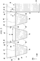
- FIG. 1 is an exploded perspective view of an unfolded state of a foldable display device, according to a first exemplary embodiment.
- FIG. 2 is a cross-sectional view of a foldable display device of FIG. 1 taken along a line II-II, and
- FIG. 3 is a partially enlarged view of FIG. 2 .
- the foldable display device 100 of the first exemplary embodiment includes a display panel 10 and a panel supporting unit 20 coupled to and supporting the display panel 10.
- the display panel 10 includes a flexible substrate 11 and a display unit 12 positioned on the flexible substrate 11.
- the display panel 10, for example, may be one among an organic light emitting panel, a liquid crystal panel, and an electrophoretic display panel.
- the display panel 10 includes a first surface S10 on which the display unit 12 is positioned and a second surface S20 that is opposite to the first surface S10.
- the first surface S10 may be a display surface and the second surface S20 may be the display surface or a non-display surface. Referring to FIG. 1 , an upper surface of the display panel 10 becomes the first surface S10, and a lower surface of the display panel 10 becomes the second surface S20.
- the display panel 10 is divided into a flat region FA and a bendable region BA.
- the display panel 10 may be divided into the bendable region BA positioned at a center and two flat regions FA positioned at respective sides of the bendable region BA. Lengths of two flat regions FA along a first direction DR1 may be equal to each other or different from each other.
- the panel supporting unit 20 faces the second surface S20 of the display panel 10 and is coupled to the display panel 10.
- the panel supporting unit 20 may include two supporting plates 30 corresponding to the two flat regions FA, and a plurality of link members 40 corresponding to the bendable region BA.
- the plurality of link members 40 may be arranged in parallel along the first direction DR1, and each of the plurality of link members 40 may have a bar shape extending along a second direction DR2 crossing the first direction DR1 and especially perpendicular to the first direction DR1.
- each vertical width a1 of the plurality of link members 40 observed on a cross-sectional view may be smaller than a vertical width a2 of the supporting plate 30.
- Each of the plurality of link members 40 has a first supporting surface 41 facing the display panel 10, and each of the two supporting plates 30 has a second supporting surface 31 facing the display panel 10.
- the bendable region BA of the display panel 10 is positioned on the plurality of first supporting surfaces 41, and the flat regions FA are positioned on the two second supporting surfaces 31.
- the plurality of first supporting surfaces 41 and the two second supporting surfaces 31 extend in parallel along the first direction DR1 and have the same height. Especially the first supporting surfaces 41 and the second supporting surfaces 31 are aligned with each other to form a common plane.
- the flat region FA of the display panel 10 may be adhered to the second supporting surface 31 of the supporting plate 30 by an adhesion layer (not shown).
- the bendable region BA of the display panel 10 is not adhered to the plurality of link members 40. That is, the flat region FA of the display panel 10 is fixed to the second supporting surface 31, however the bendable region BA may be in contact with the plurality of first supporting surfaces 41 without being adhered thereto or may be slightly floated from the plurality of first supporting surfaces 41.
- Each of the plurality of link members 40 may include a first protrusion part 42 protruded upward from both end parts along the second direction DR2.
- the protrusion direction is along a third direction DR3 perpendicular to the first and second directions DR1, DR2, but each first protrusion part 42 has a distinct extension in the second direction DR2 and also in the first direction DR1.
- the supporting plate 30 may include a second protrusion part 32 protruded upward from both end parts along the second direction DR2.
- the above definition with respect to the first protrusion part 42 also applies for the second protrusion part 32.
- the first protrusion part 42 and the second protrusion part 32 do not overlap the display panel 10, and may be positioned outside of the longitudinal sides of the display panel 10.
- protruded upward means to be protruded along a third direction DR3 based on the drawing, and this has the same meaning as being protruded in a direction from the second surface S20 of the display panel 10 toward the first surface S10 of the display panel 10.
- the plurality of first protrusion parts 42 and the two second protrusion parts 32 are mutually coupled by a plurality of rotation coupling parts 50.
- Each of the plurality of rotation coupling parts 50 has a rotational axis 51, and each of the plurality of link members 40 may be rotated about the two rotational axes 51 extending along the second direction DR2.
- the rotation coupling parts 50 may be constructed, for example, of a hinge assembly having a hinge axis. In this case, the rotational axis 51 may correspond to the hinge axis.
- FIG. 4 is a cross-sectional view showing an example of a rotation assembly shown in FIG. 3 .
- the rotation coupling part 50 may include a first link arm 52 connected to any one first protrusion part 42, a second link arm 53 connected to an adjacent first protrusion part 42, and the rotational axis 51 that hinge-couples the first link arm 52 and the second link arm 53 by penetrating through them.
- the rotation coupling part 50 is not limited to the illustrated example.
- each of the plurality of link members 40 includes two lower inclination surfaces 43 positioned under the first supporting surface 41.
- Each of the plurality of first protrusion parts 42 includes two upper inclination surfaces 44.
- the upper inclination surfaces 44 have the same slope as the lower inclination surfaces 43, and may be positioned on the same plane as the lower inclination surface 43 on the cross-section.
- the terms under and upper, higher and lower as well as horizontal and vertical refer to a state of the display device 100, in which the display device 100 is unfolded and the display panel 10 is positioned horizontally with the first surface S10 facing upwardly and the second surface S20 facing downwardly, as can be seen for example in FIG. 3 , i.e. in a cross-sectional view along the first and third directions DR1, DR3.
- the rotational axis 51 and the rotation coupling part 50 may be positioned at an upper end part of the upper inclination surface 44.
- the two rotational axes 51 of a link member 40 are positioned to be higher than the first supporting surface 41, and each rotational axis 51 is positioned at a predetermined separation distance G1 (referring to FIG. 3 ) from the first supporting surface 41 along the third direction DR3 (matching a direction from the second surface S20 toward the first surface S10 in the unfolded state).
- the separation distance G1 of the rotational axis 51 for the first supporting surface 41 is larger than the thickness of the display panel 10. Accordingly, two rotational axes 51 are positioned to be higher than the first surface S10 of the display panel 10, and each rotational axis 51 is positioned at a predetermined separation distance G2 from the first surface S10 along the third direction DR3.
- each link member 40 a distance D (referring to FIG. 3 ) between the two rotational axes 51 is larger than a width W (referring to FIG. 3 ) of the first supporting surface 41.
- Each of the plurality of first protrusion parts 42 may include two vertical surfaces 45 connected to the two upper inclination surfaces 44, respectively.
- the vertical surface 45 is in contact with the vertical surface 45 of an adjacent first protrusion part 42, and the upper inclination surface 44 is separated from the upper inclination surface 44 of the adjacent first protrusion part 42.
- the plurality of first supporting surfaces 41 are separated from each other, and the lower inclination surface 43 is separated from the lower inclination surface 43 of the adjacent link member 40.
- the first supporting surface 41 of an outermost link member 40 among the plurality of link members 40 is separated from the second supporting surface 31 of the supporting plate 30, and the upper inclination surface 44 and the lower inclination surface 43 of the outermost link member 40 are separated from an inner surface of the supporting plate 30.
- FIG. 5 is a cross-sectional view showing a folded state of the foldable display device shown in FIG. 2 .
- FIG. 6 is a partially enlarged view of FIG. 5
- FIG. 7 is a partially enlarged view of FIG. 6 .
- the foldable display device 100 of the first exemplary embodiment is changed to the folded state by rotating the plurality of link members 40 about their rotational axes 51, and the bendable region BA of the display panel 10 is bent in a circular arc shape.
- FIG. 5 shows a case in which six link members 40 are in close contact to form a semicircle on the cross-section, and the bendable region BA of the display panel 10 is bent 180°.
- the plurality of first supporting surfaces 41 are connected to each other, the plurality of link members 40 are in contact at the lower inclination surfaces 43 to each other, and the lower inclination surface 43 of the outermost link members 40 is in contact with the inner surface of the corresponding supporting plate 30.
- the plurality of first protrusion parts 42 are in contact at the upper inclination surfaces 44 to each other, and the upper inclination surface 44 of the outermost first protrusion parts 42 is in contact with the inner surface of the corresponding supporting plate 30.
- an inclination angle of the lower inclination surface 43 in the plurality of link members 40 is set as a value so that the plurality of link members 40 may be in close contact to each other to form the semicircle in the folded state.
- an edge of the first supporting surface 41 of the outermost link member 40 in the folded state is positioned at a predetermined separation distance G3 (referring to FIG. 7 ) from the second supporting surface 31 of the supporting plate 30 toward a curvature center C of the bendable region BA. That is, in the folded state, the edge of the first supporting surface 41 is not in direct contact with the edge of the second supporting surface 31 and is positioned to be closer to the curvature center C of the bendable region BA than the edge of the second supporting surface 31.
- a distance D1 (referring to FIG. 7 ) between the rotational axis 51 and the first supporting surface 41 is larger than the distance D2 (referring to FIG. 7 ) between the rotational axis 51 and the second supporting surface 31.
- the difference of the distances D1 and the D2 is represented by the above-described separation distance G3 in the folded state.
- the plurality of first supporting surfaces 41 are separated from each other as shown in FIG. 3 .
- a sum of the lengths of the plurality of first supporting surfaces 41 is shorter than the length of an imaginary line connecting two second supporting surfaces 31 in the unfolded state.
- the plurality of first supporting surfaces 41 in contact with each other in the folded state may be positioned inside of an imaginary circular arc ISC (referring to FIG. 6 ) that connects two second supporting surfaces 31 toward the curvature center C.
- At least one point among a plurality of points in which two adjacent first supporting surfaces 41 are in contact may be positioned on the imaginary circular arc ISC, and the rest of the first supporting surface 41 may be positioned inside the circular arc ISC by a distance from the imaginary circular arc ISC toward the curvature center C.
- the second surface S20 of the display panel 10 in the bendable region BA may be positioned on the imaginary circular arc ISC.
- the plurality of link members 40 are pushed and positioned to the inside from the second surface S20 of the bendable region BA (in the direction toward the imaginary circular arc ISC or the curvature center C of the bendable region BA) by the above-described height difference of the rotational axis 51 and the first supporting surface 41 in the folded state. Accordingly, the plurality of link members 40 minimize a deformation of the display panel 10 without imparting an excessive stress to the display panel 10 in the folded state.
- FIG. 8 is a partially enlarged cross-sectional view showing an unfolded state of a foldable display device, according to a comparative example
- FIG. 9 is a partially enlarged cross-sectional view showing a folded state of the foldable display device shown in FIG. 8 .
- a plurality of link members 401 are mutually coupled by the plurality of rotation coupling parts 50 having the rotational axis 51, and each of the plurality of link members 401 may be rotated about two rotational axes 51.
- two rotational axes 51 are positioned at the same height as the first supporting surface 411 and the second supporting surface 311 facing the display panel 10.
- a plurality of points P1 and P2 (referring to FIG. 9 ) where two adjacent first supporting surfaces 411 are in contact are positioned outside the imaginary circular arc ISC that connects the two second supporting surfaces 311. Accordingly, the plurality of link members 401 push and deform the display panel 10 in an outward direction away from the curvature center C of the imaginary circular arc ISC, particularly at the plurality of points P1 and P2 where the two adjacent first supporting surfaces 411 are in contact.
- the display panel 10 may have a multilayer including a flexible substrate, a display unit, an encapsulation layer, a touch sensor unit, a polarization film, a cover window, etc.
- a hard coating layer of the cover window or an inorganic insulating layer of the display unit may be brittle and prone to a breakage due to the tensile stress caused by the deformation in the bendable region BA. Accordingly, in the foldable display device of the comparative example, the chances are high that a certain layer of the display panel 10 may be damaged by the stress in the bendable region BA in the folded state.
- the foldable display device 100 of the first exemplary embodiment shown in FIGS. 1 to 7 minimizes the amount of deformation that may be caused by the plurality of link members 40 pushing the display panel 10 due to the height difference of the rotational axis 51 and the first supporting surface 41 in the folded state.
- the height difference decreases the chance of breaking layers of the display panel 10, thereby increasing the durability of the display panel 10.
- the upper surface of the first protrusion part 42 and the second protrusion part 32 is positioned to be higher than the first surface S10 of the display panel 10. That is, in the unfolded state, the upper surface of the first protrusion part 42 and the second protrusion part 32 are positioned at a predetermined separation distance G4 (referring to FIG. 2 and FIG. 3 ) from the first surface S10 of the display panel 10 along the third direction DR3.
- the external impact When an external impact such as a drop impact is applied to the foldable display device 100, the external impact may be firstly absorbed by the first protrusion part 42 and the second protrusion part 32 that are protruded above the display panel 10.
- the first protrusion part 42 and the second protrusion part 32 serve as protection members of the display panel 10 that can suppress the damage of the display panel 10 caused by the external impact.
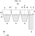
- FIG. 10 is a partially enlarged cross-sectional view showing an unfolded state of a foldable display device, according to a second exemplary embodiment
- FIG. 11 is a view showing the folded state of a foldable display device shown in FIG. 10 .
- each of a plurality of first supporting surfaces 41 includes two chamfered surfaces 41 b positioned at both edges thereof.
- each of the plurality of first supporting surfaces 41 may include a center surface 41 a parallel to the first direction DR1 respectively extending in the first and second directions DR1, DR2, and the two chamfered surfaces 41 b positioned at respective sides of the center surface 41 a in the first direction DR1.
- the widths of the two chamfered surfaces 41 b may be equal to each other, and a chamfer angle of the two chamfered surfaces 41 b may be equal to each other.
- the plurality of first supporting surfaces 41 are right and left symmetrical.
- each of the plurality of first supporting surfaces 41 includes the two chamfered surfaces 41 b, a plurality of points where two adjacent first supporting surfaces 41 are in contact in the folded state are positioned to be closer to the curvature center C than in the above-described first exemplary embodiment.
- two adjacent first supporting surfaces 41 are in contact at the point P3in the folded state whereas, in the case of the second exemplary embodiment, two adjacent first supporting surface 41 are in contact at the point P4 in the folded state.
- the point P4 is positioned to be closer to the curvature center C than the point P3.
- the foldable display device 200 of the second exemplary embodiment may separate the first supporting surface 41 of the link member 40 from the display panel 10 by the distance G5 between the point P3 and the point P4. Accordingly, the plurality of link members 40 may further reduce the deformation of the display panel 10 in the folded state and may minimize the stress imparted on the display panel 10.
- the foldable display device 200 of the second exemplary embodiment is made of the same configurations as or similar to the first exemplary embodiment except for each first supporting surface 41 of the plurality of link members 40 including two chamfered surfaces 41 b.
- FIG. 12 is a cross-sectional view showing an unfolded state of a foldable display device, according to a third exemplary embodiment
- FIG. 13 is a partially enlarged view showing a folded state of the foldable display device shown in FIG. 12 .
- the panel supporting unit 20 includes a center supporting plate 60 positioned between the plurality of link members 40.
- the center supporting plate 60 is positioned at the center of the panel supporting unit 20, and the plurality of link members 40 and two supporting plates 30 may be disposed symmetrically right and left with respect to the center supporting plate 60.
- the center supporting plate 60 includes a third supporting surface 61 facing the display panel 10 and a third protrusion part 62 protruded upward from both end parts of the center supporting plate 60 in the second direction DR2.
- the above definition with respect to the first and second protrusion parts 42, 32 also applies for the third protrusion part 62.
- the first protrusion parts 42, and the two second protrusion parts 32, and the third protrusion part 62, are mutually coupled by a plurality of rotation coupling parts 50.
- Each of the plurality of rotation coupling parts 50 includes the rotational axis 51, and each of the plurality of link members 40 may be rotated about two rotational axes 51 extending along the second direction DR2.
- the plurality of link members 40 are in contact at the lower inclination surface 43 to each other, and the plurality of first supporting surfaces 41 correspond to the circular arc of 90° connecting the supporting plate 30 and the center supporting plate 60.
- the display panel 10 may be divided into three flat regions FA corresponding to the center supporting plate 60 and two supporting plates 30, and two bendable regions BA corresponding to the plurality of link members 40.
- the foldable display device 300 has the same as or similar configurations to the first exemplary embodiment except for the center supporting plate 60 positioned between the plurality of link members 40.
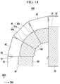
- FIG. 14 is a partially enlarged cross-sectional view showing a folded state of a foldable display device, according to a fourth exemplary embodiment.
- each of the plurality of first supporting surfaces 41 includes two chamfered surfaces 41 b positioned at respective edges thereof. That is, each of the plurality of first supporting surfaces 41 includes a center surface 41 a parallel to the first direction DR1 in the unfolded state and two chamfered surfaces 41 b positioned at respective sides of the center surface 41 a.
- the operation of the chamfered surface 41 b is the same as described above in the second exemplary embodiment.
- the foldable display device 400 of the fourth exemplary embodiment has the same or similar configuration to the third exemplary embodiment except for each of the plurality of first supporting surfaces 41 including two chamfered surfaces 41 b.
Landscapes
- Engineering & Computer Science (AREA)
- Physics & Mathematics (AREA)
- Theoretical Computer Science (AREA)
- General Physics & Mathematics (AREA)
- Computer Hardware Design (AREA)
- General Engineering & Computer Science (AREA)
- Human Computer Interaction (AREA)
- Nonlinear Science (AREA)
- Devices For Indicating Variable Information By Combining Individual Elements (AREA)
- Mathematical Physics (AREA)
- Chemical & Material Sciences (AREA)
- Crystallography & Structural Chemistry (AREA)
- Optics & Photonics (AREA)
- Liquid Crystal (AREA)
- Electroluminescent Light Sources (AREA)
Abstract
Description
- The present disclosure relates to a foldable display device. More particularly, the present disclosure relates to a structure of a panel supporting unit coupled to a display panel.
- A flexible display panel includes a flexible substrate and a display unit disposed on the flexible substrate to impart an easy bending property. Recently, a foldable display device capable of being bent or folded in half has been under development by using the flexible display panel.
- The foldable display device includes the flexible display panel and a panel supporting unit that is coupled to the flexible display panel. The panel supporting unit has a structure to allow the flexible display panel to be bent or folded. The panel supporting unit must stably support the flexible display panel without deforming the flexible display panel in a folded state.
- The above information disclosed in this Background section is for enhancement of understanding of the background of the present disclosure and therefore it may contain information that may not form a prior art that is known to a person of ordinary skill in the art.
- The present disclosure provides a foldable display device reducing a stress applied to the flexible display panel in a folded state.
- A foldable display device according to an exemplary embodiment includes a display panel and a panel supporting unit. The display panel has a first surface in which a display unit is positioned, and a second surface opposite to the first surface and including a bendable region. A panel supporting unit faces the second surface and is coupled to the display panel. The panel supporting unit includes a plurality of link members arranged in parallel along a first direction, i.e. parallel to each other and one behind another in the first direction, corresponding to the bendable region of the display panel in an unfolded state respectively defining the bendable region of the display panel. Each of the plurality of link members has a first supporting surface facing the display panel and is coupled to be rotated about two rotational axes in a folded state. The two rotational axes of each of the plurality of link members are separated from the first supporting surface in a direction from the second surface toward the first surface.
- A plurality of first supporting surfaces included in the plurality of link members may be separated from each other in the unfolded state, and a distance between the two rotational axes of each of the plurality of link members may be larger than a width of the first supporting surface. Each of the plurality of link members may further include two lower inclination surfaces positioned under both end parts of the first supporting surface and connected to the first supporting surface, and two first protrusion parts positioned at both end parts of the first supporting surface along a second direction crossing the first direction.
- Each of the two first protrusion parts may include two upper inclination surfaces positioned on the same plane as the two lower inclination surfaces on a cross-section, and the two rotational axes may be positioned at an upper end part of the two upper inclination surfaces. Each of the two first protrusion parts may further include two vertical surfaces positioned on the two upper inclination surfaces, and the two vertical surfaces in the unfolded state may be in contact with the vertical surfaces of the first protrusion parts of adjacent link members that are adjacent along the first direction.
- In the folded state, the plurality of first supporting surfaces may be connected to each other, the two lower inclination surfaces may be in close contact with the lower inclination surfaces of adjacent link members, and the bendable region may be bent in a circular arc shape.
- The display panel may further include two flat regions positioned at both sides of the bendable region, and the panel supporting unit may further include two supporting plates corresponding to the two flat regions. Each of the two supporting plates may include a second supporting surface facing the display panel, and two second protrusion parts positioned at both end parts of the second supporting surface along the second direction. The two second protrusion parts and a plurality of first protrusion parts included in the plurality of link member may be mutually connected by a respective rotation coupling part having a rotational axis.
- In the unfolded state, the two second supporting surfaces may be parallel to the plurality of first supporting surfaces, and in the folded state, an edge of an outermost first supporting surface among the plurality of first supporting surfaces may be separated from the second supporting surface toward a curvature center of the bendable region. In the folded state, the plurality of first supporting surfaces may be positioned inside of an imaginary circular arc connecting the two second supporting surfaces.
- The two second protrusion parts may be positioned to face each other outside both sides of the display panel, and the plurality of first protrusion parts may be positioned to face each other outside both sides of the display panel. The upper surface of the first protrusion part and the upper surface of the second protrusion part may be separated from the first surface in the direction from the second surface toward the first surface.
- The plurality of first supporting surfaces may respectively include a center surface and two chamfered surfaces positioned at both sides of the center surface. The two chamfered surfaces may have the same width and the same chamfer angle.
- The panel supporting unit may further include a center supporting plate, and the plurality of link members may be positioned at both sides of the center supporting plate. Each of the plurality of first supporting surfaces may include a center surface and two chamfered surfaces positioned at both sides of the center surface.
- According to exemplary embodiments, in the folded state, a plurality of link members can reduce a deformation of the display panel and decrease a probability of damaging the display panel. In addition, the first protrusion part and the second protrusion part of the panel supporting unit can serve as protection members of the display panel and suppress the damage of the display panel due to an external impact.
-
-
FIG. 1 is an exploded perspective view of an unfolded state of a foldable display device, according to a first exemplary embodiment. -
FIG. 2 is a cross-sectional view of a foldable display device ofFIG. 1 taken along a line II-II. -
FIG. 3 is a partially enlarged view ofFIG. 2 . -
FIG. 4 is a cross-sectional view showing an example of a rotation assembly shown inFIG. 3 . -
FIG. 5 is a cross-sectional view showing a folded state of the foldable display device shown inFIG. 2 . -
FIG. 6 is a partially enlarged view ofFIG. 5 . -
FIG. 7 is a partially enlarged view ofFIG. 6 . -
FIG. 8 is a partially enlarged cross-sectional view showing an unfolded state of a foldable display device, according to a comparative example. -
FIG. 9 is a partially enlarged cross-sectional view showing a folded state of the foldable display device shown inFIG. 8 . -
FIG. 10 is a partially enlarged cross-sectional view showing an unfolded state of a foldable display device, according to a second exemplary embodiment. -
FIG. 11 is a view showing a folded state of the foldable display device shown inFIG. 10 . -
FIG. 12 is a cross-sectional view showing an unfolded state of a foldable display device, according to a third exemplary embodiment. -
FIG. 13 is a partially enlarged view showing a folded state of the foldable display device shown inFIG. 12 . -
FIG. 14 is a partially enlarged cross-sectional view showing a folded state of a foldable display device, according to a fourth exemplary embodiment. - The present disclosure will be described more fully hereinafter with reference to the accompanying drawings, in which exemplary embodiments of the present disclosure are shown. As those skilled in the art would realize, the described embodiments may be modified in various different ways, without departing from the scope of the present claims.
- Descriptions of parts not related to the present disclosure may be omitted, and like reference numerals designate like elements throughout the specification.
- Further, since sizes and thicknesses of constituent members shown in the accompanying drawings may be arbitrarily given for better understanding and ease of description, the present disclosure is not limited to the illustrated sizes and thicknesses. In the drawings, the thickness of layers, films, panels, regions, etc., may be exaggerated for clarity. In the drawings, for better understanding and ease of description, the thicknesses of some layers and areas may be exaggerated.
- It will be understood that when an element such as a layer, film, region, or substrate is referred to as being "on" another element, it can be directly on the other element or one or more intervening elements may be present. In contrast, when an element is referred to as being "directly on" another element, there may be no intervening element present.
- Further, in the specification, the word "on" or "above" means positioned on or below the object portion, and does not necessarily mean positioned on the upper side of the object portion based on a gravitational direction.
- In addition, unless explicitly described to the contrary, the word "comprise" and variations such as "comprises" or "comprising" will be understood to imply the inclusion of stated elements but not the exclusion of any other elements.
- Further, in the specification, the phrase "in a plan view" means when an object portion is viewed from above, and the phrase "in a cross-sectional view" means when a cross-section taken by vertically cutting an object portion is viewed from a side.
-
FIG. 1 is an exploded perspective view of an unfolded state of a foldable display device, according to a first exemplary embodiment.FIG. 2 is a cross-sectional view of a foldable display device ofFIG. 1 taken along a line II-II, andFIG. 3 is a partially enlarged view ofFIG. 2 . - Referring to
FIG. 1 to FIG. 3 , thefoldable display device 100 of the first exemplary embodiment includes adisplay panel 10 and apanel supporting unit 20 coupled to and supporting thedisplay panel 10. - The
display panel 10 includes aflexible substrate 11 and adisplay unit 12 positioned on theflexible substrate 11. Thedisplay panel 10, for example, may be one among an organic light emitting panel, a liquid crystal panel, and an electrophoretic display panel. - The
display panel 10 includes a first surface S10 on which thedisplay unit 12 is positioned and a second surface S20 that is opposite to the first surface S10. The first surface S10 may be a display surface and the second surface S20 may be the display surface or a non-display surface. Referring toFIG. 1 , an upper surface of thedisplay panel 10 becomes the first surface S10, and a lower surface of thedisplay panel 10 becomes the second surface S20. - The
display panel 10 is divided into a flat region FA and a bendable region BA. For example, thedisplay panel 10 may be divided into the bendable region BA positioned at a center and two flat regions FA positioned at respective sides of the bendable region BA. Lengths of two flat regions FA along a first direction DR1 may be equal to each other or different from each other. - The
panel supporting unit 20 faces the second surface S20 of thedisplay panel 10 and is coupled to thedisplay panel 10. Thepanel supporting unit 20 may include two supportingplates 30 corresponding to the two flat regions FA, and a plurality oflink members 40 corresponding to the bendable region BA. - The plurality of
link members 40 may be arranged in parallel along the first direction DR1, and each of the plurality oflink members 40 may have a bar shape extending along a second direction DR2 crossing the first direction DR1 and especially perpendicular to the first direction DR1. Referring toFIG. 3 , each vertical width a1 of the plurality oflink members 40 observed on a cross-sectional view may be smaller than a vertical width a2 of the supportingplate 30. - Each of the plurality of
link members 40 has a first supportingsurface 41 facing thedisplay panel 10, and each of the two supportingplates 30 has a second supportingsurface 31 facing thedisplay panel 10. The bendable region BA of thedisplay panel 10 is positioned on the plurality of first supportingsurfaces 41, and the flat regions FA are positioned on the two second supporting surfaces 31. In the unfolded state, the plurality of first supportingsurfaces 41 and the two second supporting surfaces 31 extend in parallel along the first direction DR1 and have the same height. Especially the first supportingsurfaces 41 and the second supportingsurfaces 31 are aligned with each other to form a common plane. - The flat region FA of the
display panel 10 may be adhered to the second supportingsurface 31 of the supportingplate 30 by an adhesion layer (not shown). In contrast, the bendable region BA of thedisplay panel 10 is not adhered to the plurality oflink members 40. That is, the flat region FA of thedisplay panel 10 is fixed to the second supportingsurface 31, however the bendable region BA may be in contact with the plurality of first supportingsurfaces 41 without being adhered thereto or may be slightly floated from the plurality of first supporting surfaces 41. - Each of the plurality of
link members 40 may include afirst protrusion part 42 protruded upward from both end parts along the second direction DR2. This means, the protrusion direction is along a third direction DR3 perpendicular to the first and second directions DR1, DR2, but eachfirst protrusion part 42 has a distinct extension in the second direction DR2 and also in the first direction DR1. The supportingplate 30 may include asecond protrusion part 32 protruded upward from both end parts along the second direction DR2. The above definition with respect to thefirst protrusion part 42 also applies for thesecond protrusion part 32. Thefirst protrusion part 42 and thesecond protrusion part 32 do not overlap thedisplay panel 10, and may be positioned outside of the longitudinal sides of thedisplay panel 10. - Here, the expression "protruded upward" means to be protruded along a third direction DR3 based on the drawing, and this has the same meaning as being protruded in a direction from the second surface S20 of the
display panel 10 toward the first surface S10 of thedisplay panel 10. - The plurality of
first protrusion parts 42 and the twosecond protrusion parts 32 are mutually coupled by a plurality ofrotation coupling parts 50. Each of the plurality ofrotation coupling parts 50 has arotational axis 51, and each of the plurality oflink members 40 may be rotated about the tworotational axes 51 extending along the second direction DR2. Therotation coupling parts 50 may be constructed, for example, of a hinge assembly having a hinge axis. In this case, therotational axis 51 may correspond to the hinge axis. -
FIG. 4 is a cross-sectional view showing an example of a rotation assembly shown inFIG. 3 . - Referring to
FIG. 4 , therotation coupling part 50 may include afirst link arm 52 connected to any onefirst protrusion part 42, asecond link arm 53 connected to an adjacentfirst protrusion part 42, and therotational axis 51 that hinge-couples thefirst link arm 52 and thesecond link arm 53 by penetrating through them. Therotation coupling part 50 is not limited to the illustrated example. - Again referring to
FIG. 1 to FIG. 3 , each of the plurality oflink members 40 includes two lower inclination surfaces 43 positioned under the first supportingsurface 41. Each of the plurality offirst protrusion parts 42 includes two upper inclination surfaces 44. The upper inclination surfaces 44 have the same slope as the lower inclination surfaces 43, and may be positioned on the same plane as thelower inclination surface 43 on the cross-section. When used herein, the terms under and upper, higher and lower as well as horizontal and vertical refer to a state of thedisplay device 100, in which thedisplay device 100 is unfolded and thedisplay panel 10 is positioned horizontally with the first surface S10 facing upwardly and the second surface S20 facing downwardly, as can be seen for example inFIG. 3 , i.e. in a cross-sectional view along the first and third directions DR1, DR3. - The
rotational axis 51 and therotation coupling part 50 may be positioned at an upper end part of theupper inclination surface 44. The tworotational axes 51 of alink member 40 are positioned to be higher than the first supportingsurface 41, and eachrotational axis 51 is positioned at a predetermined separation distance G1 (referring toFIG. 3 ) from the first supportingsurface 41 along the third direction DR3 (matching a direction from the second surface S20 toward the first surface S10 in the unfolded state). - The separation distance G1 of the
rotational axis 51 for the first supportingsurface 41 is larger than the thickness of thedisplay panel 10. Accordingly, tworotational axes 51 are positioned to be higher than the first surface S10 of thedisplay panel 10, and eachrotational axis 51 is positioned at a predetermined separation distance G2 from the first surface S10 along the third direction DR3. - In addition, in each
link member 40, a distance D (referring toFIG. 3 ) between the tworotational axes 51 is larger than a width W (referring toFIG. 3 ) of the first supportingsurface 41. Each of the plurality offirst protrusion parts 42 may include twovertical surfaces 45 connected to the two upper inclination surfaces 44, respectively. - In the unfolded state, the
vertical surface 45 is in contact with thevertical surface 45 of an adjacentfirst protrusion part 42, and theupper inclination surface 44 is separated from theupper inclination surface 44 of the adjacentfirst protrusion part 42. The plurality of first supportingsurfaces 41 are separated from each other, and thelower inclination surface 43 is separated from thelower inclination surface 43 of theadjacent link member 40. - In the unfolded state, the first supporting
surface 41 of anoutermost link member 40 among the plurality oflink members 40 is separated from the second supportingsurface 31 of the supportingplate 30, and theupper inclination surface 44 and thelower inclination surface 43 of theoutermost link member 40 are separated from an inner surface of the supportingplate 30. -
FIG. 5 is a cross-sectional view showing a folded state of the foldable display device shown inFIG. 2 .FIG. 6 is a partially enlarged view ofFIG. 5 , andFIG. 7 is a partially enlarged view ofFIG. 6 . - Referring to
FIG. 5 to FIG. 7 , thefoldable display device 100 of the first exemplary embodiment is changed to the folded state by rotating the plurality oflink members 40 about theirrotational axes 51, and the bendable region BA of thedisplay panel 10 is bent in a circular arc shape.FIG. 5 shows a case in which sixlink members 40 are in close contact to form a semicircle on the cross-section, and the bendable region BA of thedisplay panel 10 is bent 180°. - In the folded state, the plurality of first supporting
surfaces 41 are connected to each other, the plurality oflink members 40 are in contact at the lower inclination surfaces 43 to each other, and thelower inclination surface 43 of theoutermost link members 40 is in contact with the inner surface of the corresponding supportingplate 30. The plurality offirst protrusion parts 42 are in contact at the upper inclination surfaces 44 to each other, and theupper inclination surface 44 of the outermostfirst protrusion parts 42 is in contact with the inner surface of the corresponding supportingplate 30. - Further, in the folded state, the two adjacent
vertical surfaces 45 are spread, and thevertical surface 45 of the outermostfirst protrusion parts 42 is separated from the inner surface of the corresponding supportingplate 30. An inclination angle of thelower inclination surface 43 in the plurality oflink members 40 is set as a value so that the plurality oflink members 40 may be in close contact to each other to form the semicircle in the folded state. - Because two
rotational axes 51 are positioned to be higher than the first supportingsurface 41 in each of the plurality oflink member 40, an edge of the first supportingsurface 41 of theoutermost link member 40 in the folded state is positioned at a predetermined separation distance G3 (referring toFIG. 7 ) from the second supportingsurface 31 of the supportingplate 30 toward a curvature center C of the bendable region BA. That is, in the folded state, the edge of the first supportingsurface 41 is not in direct contact with the edge of the second supportingsurface 31 and is positioned to be closer to the curvature center C of the bendable region BA than the edge of the second supportingsurface 31. - For the
outermost link member 40 that is connected to the supportingplate 30, a distance D1 (referring toFIG. 7 ) between therotational axis 51 and the first supportingsurface 41 is larger than the distance D2 (referring toFIG. 7 ) between therotational axis 51 and the second supportingsurface 31. The difference of the distances D1 and the D2 is represented by the above-described separation distance G3 in the folded state. - In the unfolded state, the plurality of first supporting
surfaces 41 are separated from each other as shown inFIG. 3 . This means that a sum of the lengths of the plurality of first supportingsurfaces 41 is shorter than the length of an imaginary line connecting two second supporting surfaces 31 in the unfolded state. Accordingly, the plurality of first supportingsurfaces 41 in contact with each other in the folded state may be positioned inside of an imaginary circular arc ISC (referring toFIG. 6 ) that connects two second supporting surfaces 31 toward the curvature center C. - For example, at least one point among a plurality of points in which two adjacent first supporting
surfaces 41 are in contact may be positioned on the imaginary circular arc ISC, and the rest of the first supportingsurface 41 may be positioned inside the circular arc ISC by a distance from the imaginary circular arc ISC toward the curvature center C. In the folded state, the second surface S20 of thedisplay panel 10 in the bendable region BA may be positioned on the imaginary circular arc ISC. - As above-described, the plurality of
link members 40 are pushed and positioned to the inside from the second surface S20 of the bendable region BA (in the direction toward the imaginary circular arc ISC or the curvature center C of the bendable region BA) by the above-described height difference of therotational axis 51 and the first supportingsurface 41 in the folded state. Accordingly, the plurality oflink members 40 minimize a deformation of thedisplay panel 10 without imparting an excessive stress to thedisplay panel 10 in the folded state. -
FIG. 8 is a partially enlarged cross-sectional view showing an unfolded state of a foldable display device, according to a comparative example, andFIG. 9 is a partially enlarged cross-sectional view showing a folded state of the foldable display device shown inFIG. 8 . - Referring to
FIG. 8 andFIG. 9 , a plurality oflink members 401 are mutually coupled by the plurality ofrotation coupling parts 50 having therotational axis 51, and each of the plurality oflink members 401 may be rotated about tworotational axes 51. In the unfolded state, tworotational axes 51 are positioned at the same height as the first supportingsurface 411 and the second supportingsurface 311 facing thedisplay panel 10. - In the folded state, a plurality of points P1 and P2 (referring to
FIG. 9 ) where two adjacent first supportingsurfaces 411 are in contact are positioned outside the imaginary circular arc ISC that connects the two second supporting surfaces 311. Accordingly, the plurality oflink members 401 push and deform thedisplay panel 10 in an outward direction away from the curvature center C of the imaginary circular arc ISC, particularly at the plurality of points P1 and P2 where the two adjacent first supportingsurfaces 411 are in contact. - The deformation of the
display panel 10 in the bendable region BA in the folded state can cause a tensile stress particularly at or near the plurality of points P1 and P2 where the two adjacent first supportingsurfaces 411 are in contact. The tensile stress imparted on thedisplay panel 10 due to the deformation of the plurality oflink members 401 may increase a chance of breaking a deformation-sensitive layer of thedisplay panel 10. - For example, the
display panel 10 may have a multilayer including a flexible substrate, a display unit, an encapsulation layer, a touch sensor unit, a polarization film, a cover window, etc. In this case, a hard coating layer of the cover window or an inorganic insulating layer of the display unit may be brittle and prone to a breakage due to the tensile stress caused by the deformation in the bendable region BA. Accordingly, in the foldable display device of the comparative example, the chances are high that a certain layer of thedisplay panel 10 may be damaged by the stress in the bendable region BA in the folded state. - In contrast, the
foldable display device 100 of the first exemplary embodiment shown inFIGS. 1 to 7 minimizes the amount of deformation that may be caused by the plurality oflink members 40 pushing thedisplay panel 10 due to the height difference of therotational axis 51 and the first supportingsurface 41 in the folded state. The height difference decreases the chance of breaking layers of thedisplay panel 10, thereby increasing the durability of thedisplay panel 10. - In addition, in the
foldable display device 100 of the first exemplary embodiment, the upper surface of thefirst protrusion part 42 and thesecond protrusion part 32 is positioned to be higher than the first surface S10 of thedisplay panel 10. That is, in the unfolded state, the upper surface of thefirst protrusion part 42 and thesecond protrusion part 32 are positioned at a predetermined separation distance G4 (referring toFIG. 2 andFIG. 3 ) from the first surface S10 of thedisplay panel 10 along the third direction DR3. - When an external impact such as a drop impact is applied to the
foldable display device 100, the external impact may be firstly absorbed by thefirst protrusion part 42 and thesecond protrusion part 32 that are protruded above thedisplay panel 10. In this case, thefirst protrusion part 42 and thesecond protrusion part 32 serve as protection members of thedisplay panel 10 that can suppress the damage of thedisplay panel 10 caused by the external impact. -
FIG. 10 is a partially enlarged cross-sectional view showing an unfolded state of a foldable display device, according to a second exemplary embodiment, andFIG. 11 is a view showing the folded state of a foldable display device shown inFIG. 10 . - Referring to
FIG. 10 andFIG. 11 , in thefoldable display device 200 of the second exemplary embodiment, each of a plurality of first supportingsurfaces 41 includes two chamferedsurfaces 41 b positioned at both edges thereof. - In the unfolded state, each of the plurality of first supporting
surfaces 41 may include acenter surface 41 a parallel to the first direction DR1 respectively extending in the first and second directions DR1, DR2, and the two chamferedsurfaces 41 b positioned at respective sides of thecenter surface 41 a in the first direction DR1. The widths of the two chamferedsurfaces 41 b may be equal to each other, and a chamfer angle of the two chamferedsurfaces 41 b may be equal to each other. In this case, the plurality of first supportingsurfaces 41 are right and left symmetrical. - Because each of the plurality of first supporting
surfaces 41 includes the two chamferedsurfaces 41 b, a plurality of points where two adjacent first supportingsurfaces 41 are in contact in the folded state are positioned to be closer to the curvature center C than in the above-described first exemplary embodiment. - Referring to
FIG. 11 , in the case of the first exemplary embodiment two adjacent first supportingsurfaces 41 are in contact at the point P3in the folded state whereas, in the case of the second exemplary embodiment, two adjacent first supportingsurface 41 are in contact at the point P4 in the folded state. The point P4 is positioned to be closer to the curvature center C than the point P3. - The
foldable display device 200 of the second exemplary embodiment may separate the first supportingsurface 41 of thelink member 40 from thedisplay panel 10 by the distance G5 between the point P3 and the point P4. Accordingly, the plurality oflink members 40 may further reduce the deformation of thedisplay panel 10 in the folded state and may minimize the stress imparted on thedisplay panel 10. - The
foldable display device 200 of the second exemplary embodiment is made of the same configurations as or similar to the first exemplary embodiment except for each first supportingsurface 41 of the plurality oflink members 40 including two chamferedsurfaces 41 b. -
FIG. 12 is a cross-sectional view showing an unfolded state of a foldable display device, according to a third exemplary embodiment, andFIG. 13 is a partially enlarged view showing a folded state of the foldable display device shown inFIG. 12 . - Referring to
FIG. 12 andFIG. 13 , in thefoldable display device 300 of the third exemplary embodiment, thepanel supporting unit 20 includes acenter supporting plate 60 positioned between the plurality oflink members 40. Thecenter supporting plate 60 is positioned at the center of thepanel supporting unit 20, and the plurality oflink members 40 and two supportingplates 30 may be disposed symmetrically right and left with respect to thecenter supporting plate 60. - The
center supporting plate 60 includes a third supportingsurface 61 facing thedisplay panel 10 and athird protrusion part 62 protruded upward from both end parts of thecenter supporting plate 60 in the second direction DR2. The above definition with respect to the first andsecond protrusion parts third protrusion part 62. - The
first protrusion parts 42, and the twosecond protrusion parts 32, and thethird protrusion part 62, are mutually coupled by a plurality ofrotation coupling parts 50. Each of the plurality ofrotation coupling parts 50 includes therotational axis 51, and each of the plurality oflink members 40 may be rotated about tworotational axes 51 extending along the second direction DR2. - In the folded state, the plurality of
link members 40 are in contact at thelower inclination surface 43 to each other, and the plurality of first supportingsurfaces 41 correspond to the circular arc of 90° connecting the supportingplate 30 and thecenter supporting plate 60. Thedisplay panel 10 may be divided into three flat regions FA corresponding to thecenter supporting plate 60 and two supportingplates 30, and two bendable regions BA corresponding to the plurality oflink members 40. - The
foldable display device 300 according to the third exemplary embodiment has the same as or similar configurations to the first exemplary embodiment except for thecenter supporting plate 60 positioned between the plurality oflink members 40. -
FIG. 14 is a partially enlarged cross-sectional view showing a folded state of a foldable display device, according to a fourth exemplary embodiment. - Referring to
FIG. 14 , in thefoldable display device 400 according to the fourth exemplary embodiment, each of the plurality of first supportingsurfaces 41 includes two chamferedsurfaces 41 b positioned at respective edges thereof. That is, each of the plurality of first supportingsurfaces 41 includes acenter surface 41 a parallel to the first direction DR1 in the unfolded state and two chamferedsurfaces 41 b positioned at respective sides of thecenter surface 41 a. - The operation of the chamfered
surface 41 b is the same as described above in the second exemplary embodiment. Thefoldable display device 400 of the fourth exemplary embodiment has the same or similar configuration to the third exemplary embodiment except for each of the plurality of first supportingsurfaces 41 including two chamferedsurfaces 41 b. - While the present disclosure has been described in connection with what is presently considered to be practical exemplary embodiments, it is to be understood that the present disclosure is not limited to the disclosed embodiments, but, on the contrary, is intended to cover various modifications and equivalent arrangements included within the scope of the appended claims.
Claims (15)
- A foldable display device (100, 200, 300, 400) comprising:a display panel (10) having a first surface (S10) in which a display unit (12) is positioned and a second surface (S20) opposite to the first surface (S10) and including a bendable region (BA); anda panel supporting unit (20) facing the second surface (S20) and coupled to the display panel (10),wherein the panel supporting unit (20) includes a plurality of link members (40) arranged in parallel along a first direction (DR1) one behind another corresponding to the bendable region (BA) of the display panel (10) in an unfolded state, each of the plurality of link members (40) respectively having a first supporting surface (41) facing the display panel (10) and coupled to be rotated about two rotational axes (51) in a folded state, andthe two rotational axes (51) of each of the plurality of link members (40) are separated from the first supporting surface (41) in a direction (DR3) from the second surface (S20) toward the first surface (S10).
- The foldable display device (100, 200, 300, 400) of claim 1, wherein
a plurality of first supporting surfaces (41) included in the plurality of link members (40) are separated from each other in the unfolded state, and
a distance (D) between the two rotational axes (51) of each of the plurality of link members (40) is larger than a width (W) of the first supporting surface (41). - The foldable display device (100, 200, 300, 400) of claim 2, wherein
each of the plurality of link members (40) includes two lower inclination surfaces (43) positioned under both end parts of the first supporting surface (41) and connected to the first supporting surface (41), and two first protrusion parts (42) positioned at both end parts of the first supporting surface (41) along a second direction (DR2) crossing the first direction (DR1). - The foldable display device (100, 200, 300, 400) of claim 3, wherein
each of the two first protrusion parts (42) includes two upper inclination surfaces (44) positioned on the same plane as the two lower inclination surfaces (43) on a cross-section, and
the two rotational axes (51) are positioned at an upper end part of the two upper inclination surfaces (44). - The foldable display device (100, 200, 300, 400) of claim 4, wherein
each of the two first protrusion parts (42) further includes two vertical surfaces (45) positioned on the two upper inclination surfaces (44), and
the two vertical surfaces (45) in the unfolded state are in contact with the vertical surfaces (45) of the first protrusion parts (42) of adjacent link members (40) that are adjacent along the first direction (DR1). - The foldable display device (100, 200, 300, 400) of at least one of claims claim 2 to 5, wherein
in the folded state, the plurality of first supporting surfaces (41) are connected to each other, the two lower inclination surfaces (43) are in close contact with the lower inclination surfaces (43) of adjacent link members (40), and the bendable region (BA) is bent in a circular arc shape. - The foldable display device (100, 200, 300, 400) of at least one of claims 1 to 6, wherein
the display panel (10) further includes two flat regions (FA) positioned at both sides of the bendable region (BA), and
the panel supporting unit (20) further includes two supporting plates (30) corresponding to the two flat regions (FA). - The foldable display device (100, 200, 300, 400) of claim 7, wherein
each of the two supporting plates (30) includes a second supporting surface (31) facing the display panel (10) and two second protrusion parts (32) positioned at both end parts of the second supporting surface (31) along the second direction (DR2), and
the two second protrusion parts (32) and a plurality of first protrusion parts (42) included in the plurality of link member (40) are mutually connected by a respective rotation coupling part (50) having a rotational axis (51). - The foldable display device (100, 200, 300, 400) of claim 8, wherein
in the unfolded state, the two second supporting surfaces (31) are parallel to the plurality of first supporting surfaces (41), and
in the folded state, an edge of an outermost first supporting surface (41) among the plurality of first supporting surfaces (41) is separated from the second supporting surface (31) toward a curvature center of the bendable region (BA). - The foldable display device (100, 200, 300, 400) of claim 9, wherein
in the folded state, the plurality of first supporting surfaces (41) are positioned inside of an imaginary circular arc connecting the two second supporting surfaces (31). - The foldable display device (100, 200, 300, 400) of at least one of claims 8 to 10, wherein
the two second protrusion parts (32) are positioned to face each other outside both sides of the display panel (10), and
the plurality of first protrusion parts (42) are positioned to face each other outside both sides of the display panel (10). - The foldable display device (100, 200, 300, 400) of at least one of claims 8 to 11, wherein
the upper surface of the first protrusion part (42) and the upper surface of the second protrusion part (32) are separated from the first surface (S10) in the direction (DR3) from the second surface (S20) toward the first surface (S10). - The foldable display device (100, 200, 300, 400) of at least one of claims 1 to 12, wherein
the plurality of first supporting surfaces (41) respectively include a center surface (41a) and two chamfered surfaces (41b) positioned at both sides of the center surface (41 a). - The foldable display device (100, 200, 300, 400) of claim 13, wherein
the two chamfered surfaces (41b) have the same width (W) and the same chamfer angle. - The foldable display device (100, 200, 300, 400) of at least one of claims 1 to 14, wherein
the panel supporting unit (20) further includes a center supporting plate (60), and
the plurality of link members (40) are positioned at both sides of the center supporting plate (60).
Applications Claiming Priority (1)
| Application Number | Priority Date | Filing Date | Title |
|---|---|---|---|
| KR1020160129963A KR102628024B1 (en) | 2016-10-07 | 2016-10-07 | Foldable display device |
Publications (2)
| Publication Number | Publication Date |
|---|---|
| EP3306596A1 true EP3306596A1 (en) | 2018-04-11 |
| EP3306596B1 EP3306596B1 (en) | 2021-07-21 |
Family
ID=59895090
Family Applications (1)
| Application Number | Title | Priority Date | Filing Date |
|---|---|---|---|
| EP17190634.0A Active EP3306596B1 (en) | 2016-10-07 | 2017-09-12 | Foldable display device |
Country Status (6)
| Country | Link |
|---|---|
| US (1) | US10198041B2 (en) |
| EP (1) | EP3306596B1 (en) |
| JP (1) | JP7048243B2 (en) |
| KR (1) | KR102628024B1 (en) |
| CN (1) | CN107919062B (en) |
| TW (1) | TWI746635B (en) |
Cited By (4)
| Publication number | Priority date | Publication date | Assignee | Title |
|---|---|---|---|---|
| CN112634750A (en) * | 2019-09-24 | 2021-04-09 | 三星显示有限公司 | Display device |
| CN114255665A (en) * | 2020-09-24 | 2022-03-29 | 京东方科技集团股份有限公司 | Display panel, preparation method thereof, display device and splicing display device |
| EP3846200A4 (en) * | 2018-08-30 | 2022-06-08 | Wuhan China Star Optoelectronics Semiconductor Display Technology Co., Ltd. | OLED DISPLAY DEVICE |
| US12019483B2 (en) | 2020-01-10 | 2024-06-25 | Semiconductor Energy Laboratory Co., Ltd. | Angle adjustment device, support, and display device |
Families Citing this family (55)
| Publication number | Priority date | Publication date | Assignee | Title |
|---|---|---|---|---|
| US10481634B2 (en) * | 2017-01-10 | 2019-11-19 | Lenovo (Singapore) Pte. Ltd. | Portable information device |
| KR102379216B1 (en) * | 2017-04-24 | 2022-03-28 | 삼성디스플레이 주식회사 | Display apparatus |
| KR102402183B1 (en) * | 2017-09-29 | 2022-05-27 | 엘지디스플레이 주식회사 | Foldable Display Device |
| KR102583233B1 (en) * | 2018-02-12 | 2023-09-26 | 삼성디스플레이 주식회사 | Foldable display device |
| TWI664475B (en) * | 2018-04-30 | 2019-07-01 | 友達光電股份有限公司 | Flexible display |
| US10534400B2 (en) * | 2018-05-24 | 2020-01-14 | Innolux Corporation | Foldable electronic device |
| CN108738258B (en) | 2018-05-28 | 2019-11-15 | 武汉华星光电半导体显示技术有限公司 | Bent mobile terminal |
| CN108831301B (en) * | 2018-06-15 | 2021-04-27 | 云谷(固安)科技有限公司 | Flexible display screen and flexible display device |
| CN108665812B (en) * | 2018-06-28 | 2020-12-29 | 上海天马有机发光显示技术有限公司 | A bending device and display device |
| KR102623425B1 (en) | 2018-07-10 | 2024-01-11 | 삼성디스플레이 주식회사 | Display apparatus |
| CN109256410A (en) * | 2018-07-28 | 2019-01-22 | 关军 | display panel and OLED display screen |
| KR102512482B1 (en) | 2018-07-31 | 2023-03-21 | 엘지디스플레이 주식회사 | Foldable Display |
| CN109065588B (en) * | 2018-08-09 | 2021-07-13 | 上海天马有机发光显示技术有限公司 | An OLED display panel and an OLED display device |
| US10890949B2 (en) * | 2018-10-12 | 2021-01-12 | Google Llc | Hinge mechanism by gear set with slider for foldable display device |
| CN109559639B (en) * | 2018-11-29 | 2022-04-05 | 广州国显科技有限公司 | Display panel and display device |
| CN109285459B (en) * | 2018-11-29 | 2020-10-27 | 上海天马微电子有限公司 | Foldable display panel's backup pad and foldable display device |
| CN109300403B (en) * | 2018-11-30 | 2021-07-09 | 上海天马有机发光显示技术有限公司 | A foldable display device |
| CN109523921B (en) * | 2018-12-12 | 2021-07-23 | 上海天马有机发光显示技术有限公司 | Flexible display panel and display device |
| KR102643282B1 (en) * | 2019-01-16 | 2024-03-05 | 삼성디스플레이 주식회사 | Display device |
| KR20190020303A (en) * | 2019-02-10 | 2019-02-28 | 심성구 | Foldable Devices for Display |
| CN109830185B (en) * | 2019-02-22 | 2024-05-17 | 华为技术有限公司 | Folding assembly and folding display terminal |
| CN111696437B (en) * | 2019-03-13 | 2022-06-21 | 深圳市长盈精密技术股份有限公司 | Hinge assembly and foldable display device |
| KR102720609B1 (en) | 2019-07-19 | 2024-10-24 | 삼성디스플레이 주식회사 | Flexible display device |
| TWI724807B (en) * | 2019-07-24 | 2021-04-11 | 友達光電股份有限公司 | Flexible apparatus |
| KR102668484B1 (en) * | 2019-07-29 | 2024-05-24 | 삼성디스플레이 주식회사 | Display device |
| CN110649070A (en) * | 2019-09-03 | 2020-01-03 | 武汉华星光电半导体显示技术有限公司 | Flexible substrate, flexible display panel and manufacturing method of flexible substrate |
| KR102664582B1 (en) * | 2019-09-09 | 2024-05-16 | 삼성디스플레이 주식회사 | Foldable display device |
| KR102891283B1 (en) * | 2019-09-19 | 2025-11-25 | 엘지디스플레이 주식회사 | Display device |
| US11609606B2 (en) | 2019-10-14 | 2023-03-21 | Samsung Display Co., Ltd. | Display apparatus |
| JP6884189B2 (en) * | 2019-10-29 | 2021-06-09 | レノボ・シンガポール・プライベート・リミテッド | Portable information devices and their manufacturing methods |
| WO2021088037A1 (en) | 2019-11-08 | 2021-05-14 | 京东方科技集团股份有限公司 | Array substrate and manufacturing method thereof, display panel, and display device |
| KR102862662B1 (en) * | 2019-12-12 | 2025-09-19 | 엘지디스플레이 주식회사 | Foldable display apparatus |
| CN111292625B (en) * | 2020-02-28 | 2022-07-08 | 合肥维信诺科技有限公司 | Flexible display panel and display device |
| KR102923880B1 (en) * | 2020-05-20 | 2026-02-09 | 삼성디스플레이 주식회사 | Display device |
| CN111739423B (en) * | 2020-06-30 | 2022-05-31 | 武汉华星光电半导体显示技术有限公司 | Support film and display module |
| KR20220007751A (en) * | 2020-07-09 | 2022-01-19 | 삼성디스플레이 주식회사 | Display device |
| KR102278840B1 (en) * | 2020-08-31 | 2021-07-16 | 정민우 | Foldable display device |
| KR102933558B1 (en) | 2020-11-12 | 2026-03-05 | 삼성디스플레이 주식회사 | Display device |
| KR20220065145A (en) * | 2020-11-12 | 2022-05-20 | 삼성디스플레이 주식회사 | Display device |
| KR20220077191A (en) * | 2020-11-30 | 2022-06-09 | 삼성디스플레이 주식회사 | Electronic device including support plate, and method for manufacturing the support plate |
| US11950379B2 (en) * | 2020-12-02 | 2024-04-02 | Samsung Display Co., Ltd. | Display device having support layers |
| CN112908174B (en) * | 2021-02-02 | 2022-07-12 | 武汉华星光电半导体显示技术有限公司 | Display device |
| CN117157694A (en) * | 2021-03-31 | 2023-12-01 | 三星显示有限公司 | Display device and method for manufacturing the same |
| WO2022211362A1 (en) * | 2021-03-31 | 2022-10-06 | 삼성디스플레이 주식회사 | Display device and manufacturing method therefor |
| KR102868426B1 (en) * | 2021-06-24 | 2025-10-02 | 엘지디스플레이 주식회사 | Cushion plate and display device including the same |
| CN113674625B (en) * | 2021-08-19 | 2023-05-16 | 京东方科技集团股份有限公司 | Support piece, flexible display module and display device |
| US12481326B2 (en) * | 2021-09-24 | 2025-11-25 | Beijing Boe Technology Development Co., Ltd. | Pivotable support apparatus and display apparatus |
| CN113920877B (en) * | 2021-10-20 | 2023-11-28 | 武汉华星光电半导体显示技术有限公司 | Display panel and display terminal |
| KR20230063998A (en) * | 2021-11-01 | 2023-05-10 | 삼성디스플레이 주식회사 | Window and electronic device including the same |
| CN114141146B (en) * | 2021-12-02 | 2024-01-19 | 云谷(固安)科技有限公司 | Support components and display devices |
| CN115013653B (en) * | 2022-05-26 | 2024-07-26 | 上海天马微电子有限公司 | Support assembly and display device |
| CN114697435B (en) * | 2022-06-02 | 2022-10-18 | 荣耀终端有限公司 | A folding assembly and terminal equipment |
| WO2024013844A1 (en) * | 2022-07-12 | 2024-01-18 | シャープディスプレイテクノロジー株式会社 | Foldable display |
| CN115116337A (en) * | 2022-07-25 | 2022-09-27 | 昆山国显光电有限公司 | Supporting assembly and display device |
| KR20240139120A (en) * | 2023-03-09 | 2024-09-23 | 삼성디스플레이 주식회사 | Display devices |
Citations (6)
| Publication number | Priority date | Publication date | Assignee | Title |
|---|---|---|---|---|
| WO2004047059A1 (en) * | 2002-11-21 | 2004-06-03 | Koninklijke Philips Electronics N.V. | Flexible display |
| US20080055831A1 (en) * | 2005-02-22 | 2008-03-06 | Fujifilm Corporation | Flexible Base Material and Flexible Image-Displaying Device Resistant to Plastic Deformation |
| US20100238612A1 (en) * | 2009-03-18 | 2010-09-23 | Po-Wen Hsiao | Flexible Display Device |
| WO2015100404A1 (en) * | 2013-12-24 | 2015-07-02 | Polyera Corporation | Support structures for a flexible electronic component |
| CN104851369A (en) * | 2015-06-12 | 2015-08-19 | 京东方科技集团股份有限公司 | Flexible display panel and driving method thereof, and display apparatus |
| US20160139634A1 (en) * | 2014-11-19 | 2016-05-19 | Seneka Co., Ltd. | Hinge device |
Family Cites Families (26)
| Publication number | Priority date | Publication date | Assignee | Title |
|---|---|---|---|---|
| CN2374896Y (en) * | 1998-12-24 | 2000-04-19 | 宏桦国际股份有限公司 | Device for combining CPU and radiator |
| KR20070016475A (en) * | 2005-08-04 | 2007-02-08 | 삼성전자주식회사 | LCD Display |
| TWI370419B (en) * | 2006-10-31 | 2012-08-11 | Creator Technology Bv | Flexible display supported by hinged frame |
| JP2010218102A (en) * | 2009-03-16 | 2010-09-30 | Sony Corp | Electronic equipment |
| US9176535B2 (en) * | 2011-06-03 | 2015-11-03 | Microsoft Technology Licensing, Llc | Flexible display flexure assembly |
| US8804324B2 (en) * | 2011-06-03 | 2014-08-12 | Microsoft Corporation | Flexible display overcenter assembly |
| EP2540188B1 (en) * | 2011-07-01 | 2013-11-27 | Richemont International S.A. | Dispositif de fixation de bracelets |
| ES2702795T3 (en) | 2011-07-11 | 2019-03-05 | Samsung Electronics Co Ltd | Flexible screen with screen support |
| KR101386220B1 (en) * | 2012-06-26 | 2014-04-17 | 삼성디스플레이 주식회사 | A flexible display device |
| KR101452871B1 (en) * | 2013-01-11 | 2014-10-22 | (주) 프렉코 | Foldable Flexible Display Device |
| KR101663728B1 (en) * | 2013-08-26 | 2016-10-07 | 삼성전자주식회사 | foldable electronic device having flexible display |
| KR101547640B1 (en) * | 2013-09-16 | 2015-08-27 | (주) 프렉코 | Foldable flexible display device with guide device |
| GB2520271A (en) * | 2013-11-13 | 2015-05-20 | Nokia Corp | An apparatus and method of providing an apparatus comprising a bendable portion |
| KR102251081B1 (en) | 2014-02-05 | 2021-05-13 | 삼성디스플레이 주식회사 | Flexible display apparatus |
| KR101727971B1 (en) * | 2014-02-21 | 2017-04-18 | 삼성전자주식회사 | Foldable device |
| WO2015170213A1 (en) | 2014-05-06 | 2015-11-12 | Semiconductor Energy Laboratory Co., Ltd. | Electronic device |
| CN203858554U (en) * | 2014-05-12 | 2014-10-01 | 联想(北京)有限公司 | Protective case for tablet computers |
| KR102015398B1 (en) | 2014-07-16 | 2019-08-29 | 엘지디스플레이 주식회사 | Foldable display apparatus |
| KR102263917B1 (en) | 2014-08-06 | 2021-06-11 | 엘지디스플레이 주식회사 | Foldable display apparatus |
| KR102233119B1 (en) * | 2014-09-23 | 2021-03-30 | 삼성디스플레이 주식회사 | Display device |
| KR20210068638A (en) * | 2014-10-28 | 2021-06-09 | 가부시키가이샤 한도오따이 에네루기 켄큐쇼 | Light-emitting device |
| KR102281845B1 (en) | 2014-11-11 | 2021-07-26 | 삼성디스플레이 주식회사 | Apparatus for supporting display panel |
| KR102471237B1 (en) * | 2015-01-21 | 2022-11-28 | 삼성디스플레이 주식회사 | Folderable display device |
| CN106468936A (en) * | 2015-08-14 | 2017-03-01 | 联想(北京)有限公司 | Warp architecture and electronic equipment |
| US10063677B2 (en) | 2016-03-18 | 2018-08-28 | Motorola Mobility Llc | Electronic device with flexible display and hinged housing, and corresponding systems and methods |
| KR102379216B1 (en) * | 2017-04-24 | 2022-03-28 | 삼성디스플레이 주식회사 | Display apparatus |
-
2016
- 2016-10-07 KR KR1020160129963A patent/KR102628024B1/en active Active
-
2017
- 2017-08-09 US US15/672,721 patent/US10198041B2/en active Active
- 2017-09-12 TW TW106131244A patent/TWI746635B/en active
- 2017-09-12 EP EP17190634.0A patent/EP3306596B1/en active Active
- 2017-09-28 CN CN201710897064.XA patent/CN107919062B/en active Active
- 2017-10-03 JP JP2017193343A patent/JP7048243B2/en active Active
Patent Citations (6)
| Publication number | Priority date | Publication date | Assignee | Title |
|---|---|---|---|---|
| WO2004047059A1 (en) * | 2002-11-21 | 2004-06-03 | Koninklijke Philips Electronics N.V. | Flexible display |
| US20080055831A1 (en) * | 2005-02-22 | 2008-03-06 | Fujifilm Corporation | Flexible Base Material and Flexible Image-Displaying Device Resistant to Plastic Deformation |
| US20100238612A1 (en) * | 2009-03-18 | 2010-09-23 | Po-Wen Hsiao | Flexible Display Device |
| WO2015100404A1 (en) * | 2013-12-24 | 2015-07-02 | Polyera Corporation | Support structures for a flexible electronic component |
| US20160139634A1 (en) * | 2014-11-19 | 2016-05-19 | Seneka Co., Ltd. | Hinge device |
| CN104851369A (en) * | 2015-06-12 | 2015-08-19 | 京东方科技集团股份有限公司 | Flexible display panel and driving method thereof, and display apparatus |
Cited By (5)
| Publication number | Priority date | Publication date | Assignee | Title |
|---|---|---|---|---|
| EP3846200A4 (en) * | 2018-08-30 | 2022-06-08 | Wuhan China Star Optoelectronics Semiconductor Display Technology Co., Ltd. | OLED DISPLAY DEVICE |
| CN112634750A (en) * | 2019-09-24 | 2021-04-09 | 三星显示有限公司 | Display device |
| US12019483B2 (en) | 2020-01-10 | 2024-06-25 | Semiconductor Energy Laboratory Co., Ltd. | Angle adjustment device, support, and display device |
| US12603948B2 (en) | 2020-01-10 | 2026-04-14 | Semiconductor Energy Laboratory Co., Ltd. | Angle adjustment device, support, and display device |
| CN114255665A (en) * | 2020-09-24 | 2022-03-29 | 京东方科技集团股份有限公司 | Display panel, preparation method thereof, display device and splicing display device |
Also Published As
| Publication number | Publication date |
|---|---|
| JP7048243B2 (en) | 2022-04-05 |
| KR102628024B1 (en) | 2024-01-22 |
| US20180101200A1 (en) | 2018-04-12 |
| US10198041B2 (en) | 2019-02-05 |
| JP2018060201A (en) | 2018-04-12 |
| TWI746635B (en) | 2021-11-21 |
| TW201814367A (en) | 2018-04-16 |
| CN107919062A (en) | 2018-04-17 |
| EP3306596B1 (en) | 2021-07-21 |
| KR20180039220A (en) | 2018-04-18 |
| CN107919062B (en) | 2022-01-14 |
Similar Documents
| Publication | Publication Date | Title |
|---|---|---|
| EP3306596B1 (en) | Foldable display device | |
| US10959341B2 (en) | Display device | |
| US10383239B2 (en) | Foldable display device | |
| US11477901B2 (en) | Display device | |
| CN108074488B (en) | Foldable display device | |
| US12560834B2 (en) | Flexible display device | |
| CN110021236B (en) | Display device and method for manufacturing the same | |
| CN111105707B (en) | Foldable display device | |
| US9775234B2 (en) | Flexible electronic device | |
| KR102123997B1 (en) | Flexible display | |
| WO2020216090A1 (en) | Support structure and fabrication method therefor, and display device and assembly method therefor | |
| US11903150B2 (en) | Housing structure and foldable display device having the same | |
| CN116583141A (en) | A display module and splicing display device | |
| US11800658B2 (en) | Display device | |
| US20250349230A1 (en) | Elastic member | |
| CN113870704A (en) | Display device | |
| KR102384285B1 (en) | Flexible display apparatus | |
| CN109754714B (en) | Structure for display device and display device including the same | |
| US20230280790A1 (en) | Display device |
Legal Events
| Date | Code | Title | Description |
|---|---|---|---|
| PUAI | Public reference made under article 153(3) epc to a published international application that has entered the european phase |
Free format text: ORIGINAL CODE: 0009012 |
|
| STAA | Information on the status of an ep patent application or granted ep patent |
Free format text: STATUS: THE APPLICATION HAS BEEN PUBLISHED |
|
| AK | Designated contracting states |
Kind code of ref document: A1 Designated state(s): AL AT BE BG CH CY CZ DE DK EE ES FI FR GB GR HR HU IE IS IT LI LT LU LV MC MK MT NL NO PL PT RO RS SE SI SK SM TR |
|
| AX | Request for extension of the european patent |
Extension state: BA ME |
|
| STAA | Information on the status of an ep patent application or granted ep patent |
Free format text: STATUS: REQUEST FOR EXAMINATION WAS MADE |
|
| 17P | Request for examination filed |
Effective date: 20181010 |
|
| RBV | Designated contracting states (corrected) |
Designated state(s): AL AT BE BG CH CY CZ DE DK EE ES FI FR GB GR HR HU IE IS IT LI LT LU LV MC MK MT NL NO PL PT RO RS SE SI SK SM TR |
|
| STAA | Information on the status of an ep patent application or granted ep patent |
Free format text: STATUS: EXAMINATION IS IN PROGRESS |
|
| 17Q | First examination report despatched |
Effective date: 20200211 |
|
| GRAP | Despatch of communication of intention to grant a patent |
Free format text: ORIGINAL CODE: EPIDOSNIGR1 |
|
| STAA | Information on the status of an ep patent application or granted ep patent |
Free format text: STATUS: GRANT OF PATENT IS INTENDED |
|
| INTG | Intention to grant announced |
Effective date: 20210216 |
|
| GRAS | Grant fee paid |
Free format text: ORIGINAL CODE: EPIDOSNIGR3 |
|
| GRAA | (expected) grant |
Free format text: ORIGINAL CODE: 0009210 |
|
| STAA | Information on the status of an ep patent application or granted ep patent |
Free format text: STATUS: THE PATENT HAS BEEN GRANTED |
|
| AK | Designated contracting states |
Kind code of ref document: B1 Designated state(s): AL AT BE BG CH CY CZ DE DK EE ES FI FR GB GR HR HU IE IS IT LI LT LU LV MC MK MT NL NO PL PT RO RS SE SI SK SM TR |
|
| REG | Reference to a national code |
Ref country code: GB Ref legal event code: FG4D |
|
| REG | Reference to a national code |
Ref country code: CH Ref legal event code: EP |
|
| REG | Reference to a national code |
Ref country code: NL Ref legal event code: FP |
|
| REG | Reference to a national code |
Ref country code: DE Ref legal event code: R096 Ref document number: 602017042399 Country of ref document: DE |
|
| REG | Reference to a national code |
Ref country code: AT Ref legal event code: REF Ref document number: 1413315 Country of ref document: AT Kind code of ref document: T Effective date: 20210815 |
|
| REG | Reference to a national code |
Ref country code: IE Ref legal event code: FG4D |
|
| REG | Reference to a national code |
Ref country code: LT Ref legal event code: MG9D |
|
| REG | Reference to a national code |
Ref country code: AT Ref legal event code: MK05 Ref document number: 1413315 Country of ref document: AT Kind code of ref document: T Effective date: 20210721 |
|
| PG25 | Lapsed in a contracting state [announced via postgrant information from national office to epo] |
Ref country code: SE Free format text: LAPSE BECAUSE OF FAILURE TO SUBMIT A TRANSLATION OF THE DESCRIPTION OR TO PAY THE FEE WITHIN THE PRESCRIBED TIME-LIMIT Effective date: 20210721 Ref country code: RS Free format text: LAPSE BECAUSE OF FAILURE TO SUBMIT A TRANSLATION OF THE DESCRIPTION OR TO PAY THE FEE WITHIN THE PRESCRIBED TIME-LIMIT Effective date: 20210721 Ref country code: LT Free format text: LAPSE BECAUSE OF FAILURE TO SUBMIT A TRANSLATION OF THE DESCRIPTION OR TO PAY THE FEE WITHIN THE PRESCRIBED TIME-LIMIT Effective date: 20210721 Ref country code: AT Free format text: LAPSE BECAUSE OF FAILURE TO SUBMIT A TRANSLATION OF THE DESCRIPTION OR TO PAY THE FEE WITHIN THE PRESCRIBED TIME-LIMIT Effective date: 20210721 Ref country code: BG Free format text: LAPSE BECAUSE OF FAILURE TO SUBMIT A TRANSLATION OF THE DESCRIPTION OR TO PAY THE FEE WITHIN THE PRESCRIBED TIME-LIMIT Effective date: 20211021 Ref country code: NO Free format text: LAPSE BECAUSE OF FAILURE TO SUBMIT A TRANSLATION OF THE DESCRIPTION OR TO PAY THE FEE WITHIN THE PRESCRIBED TIME-LIMIT Effective date: 20211021 Ref country code: PT Free format text: LAPSE BECAUSE OF FAILURE TO SUBMIT A TRANSLATION OF THE DESCRIPTION OR TO PAY THE FEE WITHIN THE PRESCRIBED TIME-LIMIT Effective date: 20211122 Ref country code: HR Free format text: LAPSE BECAUSE OF FAILURE TO SUBMIT A TRANSLATION OF THE DESCRIPTION OR TO PAY THE FEE WITHIN THE PRESCRIBED TIME-LIMIT Effective date: 20210721 Ref country code: FI Free format text: LAPSE BECAUSE OF FAILURE TO SUBMIT A TRANSLATION OF THE DESCRIPTION OR TO PAY THE FEE WITHIN THE PRESCRIBED TIME-LIMIT Effective date: 20210721 Ref country code: ES Free format text: LAPSE BECAUSE OF FAILURE TO SUBMIT A TRANSLATION OF THE DESCRIPTION OR TO PAY THE FEE WITHIN THE PRESCRIBED TIME-LIMIT Effective date: 20210721 |
|
| PG25 | Lapsed in a contracting state [announced via postgrant information from national office to epo] |
Ref country code: PL Free format text: LAPSE BECAUSE OF FAILURE TO SUBMIT A TRANSLATION OF THE DESCRIPTION OR TO PAY THE FEE WITHIN THE PRESCRIBED TIME-LIMIT Effective date: 20210721 Ref country code: LV Free format text: LAPSE BECAUSE OF FAILURE TO SUBMIT A TRANSLATION OF THE DESCRIPTION OR TO PAY THE FEE WITHIN THE PRESCRIBED TIME-LIMIT Effective date: 20210721 Ref country code: GR Free format text: LAPSE BECAUSE OF FAILURE TO SUBMIT A TRANSLATION OF THE DESCRIPTION OR TO PAY THE FEE WITHIN THE PRESCRIBED TIME-LIMIT Effective date: 20211022 |
|
| REG | Reference to a national code |
Ref country code: DE Ref legal event code: R097 Ref document number: 602017042399 Country of ref document: DE |
|
| PG25 | Lapsed in a contracting state [announced via postgrant information from national office to epo] |
Ref country code: DK Free format text: LAPSE BECAUSE OF FAILURE TO SUBMIT A TRANSLATION OF THE DESCRIPTION OR TO PAY THE FEE WITHIN THE PRESCRIBED TIME-LIMIT Effective date: 20210721 |
|
| REG | Reference to a national code |
Ref country code: CH Ref legal event code: PL |
|
| REG | Reference to a national code |
Ref country code: BE Ref legal event code: MM Effective date: 20210930 |
|
| PLBE | No opposition filed within time limit |
Free format text: ORIGINAL CODE: 0009261 |
|
| STAA | Information on the status of an ep patent application or granted ep patent |
Free format text: STATUS: NO OPPOSITION FILED WITHIN TIME LIMIT |
|
| PG25 | Lapsed in a contracting state [announced via postgrant information from national office to epo] |
Ref country code: SM Free format text: LAPSE BECAUSE OF FAILURE TO SUBMIT A TRANSLATION OF THE DESCRIPTION OR TO PAY THE FEE WITHIN THE PRESCRIBED TIME-LIMIT Effective date: 20210721 Ref country code: SK Free format text: LAPSE BECAUSE OF FAILURE TO SUBMIT A TRANSLATION OF THE DESCRIPTION OR TO PAY THE FEE WITHIN THE PRESCRIBED TIME-LIMIT Effective date: 20210721 Ref country code: RO Free format text: LAPSE BECAUSE OF FAILURE TO SUBMIT A TRANSLATION OF THE DESCRIPTION OR TO PAY THE FEE WITHIN THE PRESCRIBED TIME-LIMIT Effective date: 20210721 Ref country code: MC Free format text: LAPSE BECAUSE OF FAILURE TO SUBMIT A TRANSLATION OF THE DESCRIPTION OR TO PAY THE FEE WITHIN THE PRESCRIBED TIME-LIMIT Effective date: 20210721 Ref country code: EE Free format text: LAPSE BECAUSE OF FAILURE TO SUBMIT A TRANSLATION OF THE DESCRIPTION OR TO PAY THE FEE WITHIN THE PRESCRIBED TIME-LIMIT Effective date: 20210721 Ref country code: CZ Free format text: LAPSE BECAUSE OF FAILURE TO SUBMIT A TRANSLATION OF THE DESCRIPTION OR TO PAY THE FEE WITHIN THE PRESCRIBED TIME-LIMIT Effective date: 20210721 Ref country code: AL Free format text: LAPSE BECAUSE OF FAILURE TO SUBMIT A TRANSLATION OF THE DESCRIPTION OR TO PAY THE FEE WITHIN THE PRESCRIBED TIME-LIMIT Effective date: 20210721 |
|
| 26N | No opposition filed |
Effective date: 20220422 |
|
| PG25 | Lapsed in a contracting state [announced via postgrant information from national office to epo] |
Ref country code: LU Free format text: LAPSE BECAUSE OF NON-PAYMENT OF DUE FEES Effective date: 20210912 Ref country code: IT Free format text: LAPSE BECAUSE OF FAILURE TO SUBMIT A TRANSLATION OF THE DESCRIPTION OR TO PAY THE FEE WITHIN THE PRESCRIBED TIME-LIMIT Effective date: 20210721 Ref country code: IE Free format text: LAPSE BECAUSE OF NON-PAYMENT OF DUE FEES Effective date: 20210912 Ref country code: BE Free format text: LAPSE BECAUSE OF NON-PAYMENT OF DUE FEES Effective date: 20210930 |
|
| PG25 | Lapsed in a contracting state [announced via postgrant information from national office to epo] |
Ref country code: LI Free format text: LAPSE BECAUSE OF NON-PAYMENT OF DUE FEES Effective date: 20210930 Ref country code: CH Free format text: LAPSE BECAUSE OF NON-PAYMENT OF DUE FEES Effective date: 20210930 |
|
| PG25 | Lapsed in a contracting state [announced via postgrant information from national office to epo] |
Ref country code: HU Free format text: LAPSE BECAUSE OF FAILURE TO SUBMIT A TRANSLATION OF THE DESCRIPTION OR TO PAY THE FEE WITHIN THE PRESCRIBED TIME-LIMIT; INVALID AB INITIO Effective date: 20170912 |
|
| P01 | Opt-out of the competence of the unified patent court (upc) registered |
Effective date: 20230516 |
|
| PG25 | Lapsed in a contracting state [announced via postgrant information from national office to epo] |
Ref country code: CY Free format text: LAPSE BECAUSE OF FAILURE TO SUBMIT A TRANSLATION OF THE DESCRIPTION OR TO PAY THE FEE WITHIN THE PRESCRIBED TIME-LIMIT Effective date: 20210721 |
|
| PG25 | Lapsed in a contracting state [announced via postgrant information from national office to epo] |
Ref country code: MK Free format text: LAPSE BECAUSE OF FAILURE TO SUBMIT A TRANSLATION OF THE DESCRIPTION OR TO PAY THE FEE WITHIN THE PRESCRIBED TIME-LIMIT Effective date: 20210721 |
|
| PG25 | Lapsed in a contracting state [announced via postgrant information from national office to epo] |
Ref country code: MT Free format text: LAPSE BECAUSE OF FAILURE TO SUBMIT A TRANSLATION OF THE DESCRIPTION OR TO PAY THE FEE WITHIN THE PRESCRIBED TIME-LIMIT Effective date: 20210721 |
|
| PGFP | Annual fee paid to national office [announced via postgrant information from national office to epo] |
Ref country code: NL Payment date: 20250821 Year of fee payment: 9 |
|
| PGFP | Annual fee paid to national office [announced via postgrant information from national office to epo] |
Ref country code: DE Payment date: 20250820 Year of fee payment: 9 |
|
| PGFP | Annual fee paid to national office [announced via postgrant information from national office to epo] |
Ref country code: GB Payment date: 20250820 Year of fee payment: 9 |
|
| PGFP | Annual fee paid to national office [announced via postgrant information from national office to epo] |
Ref country code: FR Payment date: 20250821 Year of fee payment: 9 |
|
| PG25 | Lapsed in a contracting state [announced via postgrant information from national office to epo] |
Ref country code: TR Free format text: LAPSE BECAUSE OF FAILURE TO SUBMIT A TRANSLATION OF THE DESCRIPTION OR TO PAY THE FEE WITHIN THE PRESCRIBED TIME-LIMIT Effective date: 20210721 |