EP3306521A1 - Stereo vision system and method for a motor vehicle - Google Patents
Stereo vision system and method for a motor vehicle Download PDFInfo
- Publication number
- EP3306521A1 EP3306521A1 EP16192827.0A EP16192827A EP3306521A1 EP 3306521 A1 EP3306521 A1 EP 3306521A1 EP 16192827 A EP16192827 A EP 16192827A EP 3306521 A1 EP3306521 A1 EP 3306521A1
- Authority
- EP
- European Patent Office
- Prior art keywords
- disparity gradient
- vision system
- vertical
- vertical disparity
- images
- Prior art date
- Legal status (The legal status is an assumption and is not a legal conclusion. Google has not performed a legal analysis and makes no representation as to the accuracy of the status listed.)
- Granted
Links
Images
Classifications
-
- G—PHYSICS
- G06—COMPUTING OR CALCULATING; COUNTING
- G06V—IMAGE OR VIDEO RECOGNITION OR UNDERSTANDING
- G06V20/00—Scenes; Scene-specific elements
- G06V20/50—Context or environment of the image
- G06V20/56—Context or environment of the image exterior to a vehicle by using sensors mounted on the vehicle
-
- G—PHYSICS
- G06—COMPUTING OR CALCULATING; COUNTING
- G06V—IMAGE OR VIDEO RECOGNITION OR UNDERSTANDING
- G06V10/00—Arrangements for image or video recognition or understanding
- G06V10/10—Image acquisition
- G06V10/12—Details of acquisition arrangements; Constructional details thereof
- G06V10/14—Optical characteristics of the device performing the acquisition or on the illumination arrangements
- G06V10/143—Sensing or illuminating at different wavelengths
Definitions
- the invention relates to a stereo vision system for a motor vehicle, comprising an imaging apparatus adapted to capture images from the surrounding of the motor vehicle and a processing device adapted to perform image processing on images capture by said imaging apparatus and to control a driver assistance device depending on the result of said image processing.
- stray light swords are generated by wind shield wiper wear and precipitation smear-out by wipers.
- the source of these light swords is scratches in the windshield which come from dust, dirt and stones gathered on the wiper.
- the light swords come from scatter effects on these scratches.
- Camera systems in cars should handle light swords and other artefacts that occur in the image to avoid false braking and other erroneous behavior.
- the problem underlying the present invention is to provide a stereo vision system and method where the influence of light swords and other artefacts on the object detection is reduced.
- the invention solves this problem with the features of the independent claims.
- the invention has found out that artefacts like light swords have a characteristic disparity gradient in a vertical direction. Therefore, artefacts in the captured images can easily and reliably be determined and/or removed, by calculating and analyzing the vertical disparity gradient of the captured images.
- fx and fy are the horizontal and vertical focal lengths of the imaging apparatus 11 in pixels.
- the calculated vertical disparity gradient of the captured images is compared against a set value of an artefact, for example of a light sword.
- the calculated vertical disparity gradient may be compared against a threshold value k_thr.
- a structure in a captured image may be regarded an artefact if the calculated vertical disparity gradient is significantly larger than the threshold value.
- the vertical disparity gradient k may be compared against a value range characteristic of a particular artefact. For example, a structure in a captured image may be regarded an artefact if the vertical disparity gradient k of the structure falls within the above mentioned value range.
- a structure in a captured image may be regarded an artefact if the vertical disparity gradient of the structure is significantly larger than zero.
- the reason for this is that vertical objects of interest in many driver assistance applications, like pedestrians, other vehicles, bicylists etc. having a zero or near zero vertical disparity gradient.
- the invention may be implemented by providing a filter adapted to discard or filter out structures having a vertical disparity gradient above a pre-determined threshold and/or within a predetermined value range. Alternatively or additionally, only structures having a vertical disparity gradient around zero may be kept.
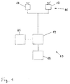
- the vision system 10 is mounted in a motor vehicle and comprises an imaging apparatus 11 for capturing images of a region surrounding the motor vehicle, for example a region in front of the motor vehicle.
- the imaging apparatus 11 comprises a plurality of optical imaging devices 12, in particular cameras, thus forming a stereo imaging apparatus 11, preferably operating in the visible and/or infrared wavelength range, where infrared covers near IR with wavelengths below 5 microns and/or far IR with wavelengths beyond 5 microns.
- the imaging apparatus 11 is coupled to a data processing device 14 adapted to process the image data received from the imaging apparatus 11.
- the data processing device 14 is preferably a digital device which is programmed or programmable and preferably comprises a microprocessor, microcontroller a digital signal processor (DSP), and/or a microprocessor part in a System-On-Chip (SoC) device, and preferably has access to, or comprises, a data memory 25.
- DSP digital signal processor
- SoC System-On-Chip
- the data processing device 14 may comprise a dedicated hardware device, like a Field Programmable Gate Array (FPGA) or an Application Specific Integrated Circuit (ASIC), or an FPGA and/or ASIC part in a System-On-Chip (SoC) device, for performing certain functions, for example controlling the capture of images by the imaging apparatus 11, receiving the electrical signal containing the image information from the imaging apparatus 11, rectifying or warping pairs of left/right images into alignment and/or creating disparity or depth images.
- the data processing device 14, or part of its functions can be realized by a System-On-Chip (SoC) device comprising, for example, FPGA, DSP, ARM and/or microprocessor functionality.
- SoC System-On-Chip
- the data processing device 14 and the memory device 25 are preferably realised in an on-board electronic control unit (ECU) and may be connected to the imaging apparatus 11 via a separate cable or a vehicle data bus.
- ECU electronice control unit
- the ECU and one or more of the imaging devices 12 can be integrated into a single unit, where a one box solution including the ECU and all imaging devices 12 can be preferred. All steps from imaging, image processing to possible activation or control of driver assistance device 18 are performed automatically and continuously during driving in real time.
- Image and data processing carried out in the processing device 14 advantageously comprises identifying and preferably also classifying possible objects (object candidates) in front of the motor vehicle, such as pedestrians, other vehicles, bicyclists and/or large animals, tracking over time the position of objects or object candidates identified in the captured images, and activating or controlling at least one driver assistance device 18 depending on an estimation performed with respect to a tracked object, for example on an estimated collision probability.
- the driver assistance device 18 may in particular comprise a display device to display information relating to a detected object.
- the invention is not limited to a display device.
- the driver assistance device 18 may in addition or alternatively comprise a warning device adapted to provide a collision warning to the driver by suitable optical, acoustical and/or haptic warning signals; one or more restraint systems such as occupant airbags or safety belt tensioners, pedestrian airbags, hood lifters and the like; and/or dynamic vehicle control systems such as braking or steering control devices.
- a warning device adapted to provide a collision warning to the driver by suitable optical, acoustical and/or haptic warning signals
- one or more restraint systems such as occupant airbags or safety belt tensioners, pedestrian airbags, hood lifters and the like
- dynamic vehicle control systems such as braking or steering control devices.
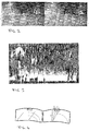
- Figure 2 shows left and right raw images captured by the stereo imaging apparatus 11 exhibiting strong artefacts known as light swords or stray light swords. These are generated by wind shield wiper wear and precipitation smear-out by wipers.
- the processing device 14 calculates a disparity image from the left and right images shown in Figure 2 , which disparity image is shown in Figure 3 .
- Using the disparity image objects in the environment of the motor vehicle, like pedestrians, other vehicles, bicyclists, large animals etc. can be detected.
- the invention in particular handles light swords due to the pattern of the windscreen wiper motion, for example wear or precipitation smear.
- These light swords come from scatter effects that are perpendicular to the motion curve of the wiper, see Figure 4 , providing a starting point for calculating on how the disparity behaves in the light swords.
- a light sword will have the angle x/y and (x+b)/y, respectively.
- the angle difference will be b/y where b is the baseline of the stereo imaging apparatus 11, i.e. the distance between the stereo imaging devices 12.
- fx and fy are the horizontal and vertical focal lengths of the imaging apparatus 11 in pixels.
- the set value k_ls for the vertical disparity gradient of a light sword is 0.23 pixels/row.
- artefacts like light swords having a vertical disparity gradient significantly different from zero, can be easily determined and/or removed from the captured images by calculating and analyzing the (average) vertical disparity gradient k of object candidates.
- the vertical disparity gradient k can be calculated for each pixel of the image, leading to a vertical disparity gradient map.
- object candidates are be detected, and an average vertical disparity gradient of each object candidate can be calculated from the vertical disparity gradient map.
- object candidates are detected, and an average vertical disparity gradient of each detected object candidate is calculated, without need to calculate a complete vertical disparity gradient map.
- Other ways of calculating an average vertical disparity gradient of each object candidate are possible.
- a filter may be applied to all object candidates filtering out such object candidates having an average vertical disparity gradient k in the range between k1 and k2, which are considered to be light swords.
- k_ls 0.23 pixels/row
- an object candidate having an average vertical disparity gradient k in the range between 0.20 and 0.26 pixels/row may be considered a light sword and therefore be discarded from further processing.
- other ranges are possible, and also other objects than light swords, having characteristic k values can be filtered out in a similar manner.
- a filter may be applied to all object candidates filtering out such object candidates having an average vertical disparity gradient k exceeding a pre-defined threshold value k_thr.
- k_ls 0.23 pixels/row
- an object candidate having an average vertical disparity gradient k equal to or above 0.20 pixels/row may be discarded from further processing.
- the set value k_r for the vertical disparity gradient of a light sword is 0.13 pixels/row, i.e., somewhat smaller than k_ls.
Landscapes
- Engineering & Computer Science (AREA)
- Physics & Mathematics (AREA)
- General Physics & Mathematics (AREA)
- Multimedia (AREA)
- Theoretical Computer Science (AREA)
- Image Processing (AREA)
- Image Analysis (AREA)
- Traffic Control Systems (AREA)
Abstract
Description
- The invention relates to a stereo vision system for a motor vehicle, comprising an imaging apparatus adapted to capture images from the surrounding of the motor vehicle and a processing device adapted to perform image processing on images capture by said imaging apparatus and to control a driver assistance device depending on the result of said image processing.
- In cars, so-called stray light swords are generated by wind shield wiper wear and precipitation smear-out by wipers. The source of these light swords is scratches in the windshield which come from dust, dirt and stones gathered on the wiper. The light swords come from scatter effects on these scratches. Camera systems in cars should handle light swords and other artefacts that occur in the image to avoid false braking and other erroneous behavior.
- The problem underlying the present invention is to provide a stereo vision system and method where the influence of light swords and other artefacts on the object detection is reduced.
- The invention solves this problem with the features of the independent claims. The invention has found out that artefacts like light swords have a characteristic disparity gradient in a vertical direction. Therefore, artefacts in the captured images can easily and reliably be determined and/or removed, by calculating and analyzing the vertical disparity gradient of the captured images.
- In the image, pixel column and pixel row are denoted as u and v, and the disparity is denoted d. Then, the following equation holds for the set value k_ls for the vertical disparity gradient of a light sword:

imaging apparatus 11 in pixels. Using the approximation fx=fy, this can be further simplified to
- Preferably the calculated vertical disparity gradient of the captured images is compared against a set value of an artefact, for example of a light sword. Herein, the set value of a light sword can for example be given by the above formula k_ls = b/y, where b is the stereo baseline of the imaging apparatus and y is the vertical windscreen height.
- Other ways of determining and/or eliminating light swords or other artefacts are possible. For example, the calculated vertical disparity gradient may be compared against a threshold value k_thr. In particular, a structure in a captured image may be regarded an artefact if the calculated vertical disparity gradient is significantly larger than the threshold value.
- Also, the vertical disparity gradient k may be compared against a value range characteristic of a particular artefact. For example, a structure in a captured image may be regarded an artefact if the vertical disparity gradient k of the structure falls within the above mentioned value range.
- It can be advantageous to consider a set value of the vertical disparity gradient k_r of the road in the artefact determination or removal. Herein, the vertical disparity gradient k_r of the road can for example be given by the formula k_r = b/H, where b is the stereo baseline of the imaging apparatus and H is the height of the imaging apparatus above ground.
- Furthermore, a structure in a captured image may be regarded an artefact if the vertical disparity gradient of the structure is significantly larger than zero. The reason for this is that vertical objects of interest in many driver assistance applications, like pedestrians, other vehicles, bicylists etc. having a zero or near zero vertical disparity gradient.
- The invention may be implemented by providing a filter adapted to discard or filter out structures having a vertical disparity gradient above a pre-determined threshold and/or within a predetermined value range. Alternatively or additionally, only structures having a vertical disparity gradient around zero may be kept.
- In the following the invention shall be illustrated on the basis of preferred embodiments with reference to the accompanying drawings, wherein:
- Fig. 1
- shows a schematic view of a vision system according to the invention;
- Fig. 2
- shows left and right raw images captured by the imaging apparatus;
- Fig. 3
- shows a calculated disparity image with light swords; and
- Fig. 4
- shows a schematic windscreen layout.
- The vision system 10 is mounted in a motor vehicle and comprises an
imaging apparatus 11 for capturing images of a region surrounding the motor vehicle, for example a region in front of the motor vehicle. Preferably theimaging apparatus 11 comprises a plurality ofoptical imaging devices 12, in particular cameras, thus forming astereo imaging apparatus 11, preferably operating in the visible and/or infrared wavelength range, where infrared covers near IR with wavelengths below 5 microns and/or far IR with wavelengths beyond 5 microns. - The
imaging apparatus 11 is coupled to adata processing device 14 adapted to process the image data received from theimaging apparatus 11. Thedata processing device 14 is preferably a digital device which is programmed or programmable and preferably comprises a microprocessor, microcontroller a digital signal processor (DSP), and/or a microprocessor part in a System-On-Chip (SoC) device, and preferably has access to, or comprises, adata memory 25. Thedata processing device 14 may comprise a dedicated hardware device, like a Field Programmable Gate Array (FPGA) or an Application Specific Integrated Circuit (ASIC), or an FPGA and/or ASIC part in a System-On-Chip (SoC) device, for performing certain functions, for example controlling the capture of images by theimaging apparatus 11, receiving the electrical signal containing the image information from theimaging apparatus 11, rectifying or warping pairs of left/right images into alignment and/or creating disparity or depth images. Thedata processing device 14, or part of its functions, can be realized by a System-On-Chip (SoC) device comprising, for example, FPGA, DSP, ARM and/or microprocessor functionality. Thedata processing device 14 and thememory device 25 are preferably realised in an on-board electronic control unit (ECU) and may be connected to theimaging apparatus 11 via a separate cable or a vehicle data bus. In another embodiment the ECU and one or more of theimaging devices 12 can be integrated into a single unit, where a one box solution including the ECU and allimaging devices 12 can be preferred. All steps from imaging, image processing to possible activation or control ofdriver assistance device 18 are performed automatically and continuously during driving in real time. - Image and data processing carried out in the
processing device 14 advantageously comprises identifying and preferably also classifying possible objects (object candidates) in front of the motor vehicle, such as pedestrians, other vehicles, bicyclists and/or large animals, tracking over time the position of objects or object candidates identified in the captured images, and activating or controlling at least onedriver assistance device 18 depending on an estimation performed with respect to a tracked object, for example on an estimated collision probability. Thedriver assistance device 18 may in particular comprise a display device to display information relating to a detected object. However, the invention is not limited to a display device. Thedriver assistance device 18 may in addition or alternatively comprise a warning device adapted to provide a collision warning to the driver by suitable optical, acoustical and/or haptic warning signals; one or more restraint systems such as occupant airbags or safety belt tensioners, pedestrian airbags, hood lifters and the like; and/or dynamic vehicle control systems such as braking or steering control devices. -
Figure 2 shows left and right raw images captured by thestereo imaging apparatus 11 exhibiting strong artefacts known as light swords or stray light swords. These are generated by wind shield wiper wear and precipitation smear-out by wipers. - As described in the foregoing, the
processing device 14 calculates a disparity image from the left and right images shown inFigure 2 , which disparity image is shown inFigure 3 . Using the disparity image, objects in the environment of the motor vehicle, like pedestrians, other vehicles, bicyclists, large animals etc. can be detected. In order to improve the accuracy of the object detection, it is beneficial to remove or discard artefacts like light swords from the disparity image. From the disparity image shown inFigure 3 it is evident that the light swords seem to stand out and are located closer to theimaging apparatus 11 than the ground. - The invention in particular handles light swords due to the pattern of the windscreen wiper motion, for example wear or precipitation smear. These light swords come from scatter effects that are perpendicular to the motion curve of the wiper, see
Figure 4 , providing a starting point for calculating on how the disparity behaves in the light swords. In the stereo images, a light sword will have the angle x/y and (x+b)/y, respectively. The angle difference will be b/y where b is the baseline of thestereo imaging apparatus 11, i.e. the distance between thestereo imaging devices 12. - In the image, pixel column and pixel row are denoted as u and v, and the disparity is denoted d. Then, the following equation holds for the set value k_ls for the vertical disparity gradient of a light sword:

imaging apparatus 11 in pixels. Using the approximation fx=fy, this can be further simplified to
- Taking as an example a windscreen height of y = 0.7 m and a baseline of b = 16 cm, the set value k_ls for the vertical disparity gradient of a light sword is 0.23 pixels/row.
- On the other hand, vertical objects with k_object = (δd/δv)obj = 0 or essentially vertical objects with k_object close to zero, like other vehicles, pedestrians, bicyclists etc., are of special interest in driver assistance applications.
- It follows from the above that artefacts like light swords, having a vertical disparity gradient significantly different from zero, can be easily determined and/or removed from the captured images by calculating and analyzing the (average) vertical disparity gradient k of object candidates. This can be done in different manners. For example, the vertical disparity gradient k can be calculated for each pixel of the image, leading to a vertical disparity gradient map. Then object candidates are be detected, and an average vertical disparity gradient of each object candidate can be calculated from the vertical disparity gradient map. In another embodiment, object candidates are detected, and an average vertical disparity gradient of each detected object candidate is calculated, without need to calculate a complete vertical disparity gradient map. Other ways of calculating an average vertical disparity gradient of each object candidate are possible.
- In one embodiment, a filter may be applied to all object candidates filtering out such object candidates having an average vertical disparity gradient k in the range between k1 and k2, which are considered to be light swords. In the above example, where k_ls = 0.23 pixels/row, an object candidate having an average vertical disparity gradient k in the range between 0.20 and 0.26 pixels/row may be considered a light sword and therefore be discarded from further processing. Of course, other ranges are possible, and also other objects than light swords, having characteristic k values can be filtered out in a similar manner.
- In another embodiment, a filter may be applied to all object candidates filtering out such object candidates having an average vertical disparity gradient k exceeding a pre-defined threshold value k_thr. In the above example, where k_ls = 0.23 pixels/row, an object candidate having an average vertical disparity gradient k equal to or above 0.20 pixels/row may be discarded from further processing.
- It can be useful to consider the vertical disparity gradient k_r of the road on which the vehicle moves. The road is usually modelled as flat. Given the camera height H above the ground and a pixel row v, vanishing point row vv and the approximation that the camera looks forward, the world distance to a pixel on the road is


- From this it follows that

- Using again the approximation fx=fy, this can be further simplified to

- Taking as an example a camera height above ground of H = 1.2 m and a baseline of b = 16 cm, the set value k_r for the vertical disparity gradient of a light sword is 0.13 pixels/row, i.e., somewhat smaller than k_ls.
- It is obvious that an image processing filter that filters out image structures having k_obj, k_r and k_ls, respectively, can distinguish between these groups of structures. Especially a filter adapted to keep only structures having k_obj by discarding structures having k >= k_r will also easily remove structure with k_ls.
Claims (12)
- A vision system (10) for a motor vehicle, comprising a stereo imaging apparatus (11) adapted to capture images from the surrounding of the motor vehicle and a processing device (14) adapted to perform image processing on images capture by said imaging apparatus (11) and to control a driver assistance device (18) depending on the result of said image processing, characterized in that said processing device (14) is adapted to calculate a disparity gradient k in a vertical direction for at least part of captured images, and to determine and/or remove artefacts in said images on the basis of said vertical disparity gradient k.
- The vision system as claimed in claim 1, characterized in that said vertical disparity gradient k is compared against a set value of an artefact.
- The vision system as claimed in claim 2, characterized in that the set value k_ls of the vertical disparity gradient of a light sword is k_ls = b/y, where b is the stereo baseline of the imaging apparatus (11) and y is the vertical windscreen height.
- The vision system as claimed in any one of the preceding claims, characterized in that said vertical disparity gradient is compared against a threshold value k_thr.
- The vision system as claimed in claim 4, characterized in that a structure in a captured image is regarded an artefact if the absolute value of the vertical disparity gradient k of said structure is significantly larger than said threshold value k_thr.
- The vision system as claimed in any one of the preceding claims, characterized in that said vertical disparity gradient is compared against a value range characteristic of a particular artefact.
- The vision system as claimed in claim 6, characterized in that a structure in a captured image is regarded an artefact if the vertical disparity gradient k of said structure falls within said value range.
- The vision system as claimed in any one of the preceding claims, characterized in that a set value k_r of the vertical disparity gradient of the road is considered in said artefact determination or removal.
- The vision system as claimed in claim 8, characterized in that the set value of the vertical disparity gradient k_r of the road is k_r = b/H, where b is the stereo baseline of the imaging apparatus and H is the height of the imaging apparatus above ground.
- The vision system as claimed in any one of the preceding claims, characterized in that a structure in a captured image is regarded an artefact if the absolute value of the vertical disparity gradient k of said structure is significantly larger than zero.
- The vision system as claimed in any one of the preceding claims, characterized in that said processing system comprises a filter adapted to discard structures having a vertical disparity gradient above a pre-determined threshold and/or to keep only structures having a vertical disparity gradient around zero.
- A stereo vision method for a motor vehicle, comprising capturing images from the surrounding of the motor vehicle, performing image processing on captured images and controlling a driver assistance device depending on the result of said image processing, characterized by calculating a disparity gradient in a vertical direction of at least a part of captured images, and determining and/or removing artefacts in said images on the basis of said vertical disparity gradient.
Priority Applications (1)
| Application Number | Priority Date | Filing Date | Title |
|---|---|---|---|
| EP16192827.0A EP3306521B1 (en) | 2016-10-07 | 2016-10-07 | Stereo vision system and method for a motor vehicle |
Applications Claiming Priority (1)
| Application Number | Priority Date | Filing Date | Title |
|---|---|---|---|
| EP16192827.0A EP3306521B1 (en) | 2016-10-07 | 2016-10-07 | Stereo vision system and method for a motor vehicle |
Publications (2)
| Publication Number | Publication Date |
|---|---|
| EP3306521A1 true EP3306521A1 (en) | 2018-04-11 |
| EP3306521B1 EP3306521B1 (en) | 2021-12-08 |
Family
ID=57113193
Family Applications (1)
| Application Number | Title | Priority Date | Filing Date |
|---|---|---|---|
| EP16192827.0A Not-in-force EP3306521B1 (en) | 2016-10-07 | 2016-10-07 | Stereo vision system and method for a motor vehicle |
Country Status (1)
| Country | Link |
|---|---|
| EP (1) | EP3306521B1 (en) |
Citations (3)
| Publication number | Priority date | Publication date | Assignee | Title |
|---|---|---|---|---|
| US20030205661A1 (en) * | 1993-02-26 | 2003-11-06 | Donnelly Corporation | Vehicle headlight control using imaging sensor |
| US20140321701A1 (en) * | 2011-06-17 | 2014-10-30 | Jad Halimeh | Method and apparatus for recognizing directional structures on a window pane of a vehicle |
| US20150156471A1 (en) * | 2012-06-01 | 2015-06-04 | Robert Bosch Gmbh | Method and device for processing stereoscopic data |
-
2016
- 2016-10-07 EP EP16192827.0A patent/EP3306521B1/en not_active Not-in-force
Patent Citations (3)
| Publication number | Priority date | Publication date | Assignee | Title |
|---|---|---|---|---|
| US20030205661A1 (en) * | 1993-02-26 | 2003-11-06 | Donnelly Corporation | Vehicle headlight control using imaging sensor |
| US20140321701A1 (en) * | 2011-06-17 | 2014-10-30 | Jad Halimeh | Method and apparatus for recognizing directional structures on a window pane of a vehicle |
| US20150156471A1 (en) * | 2012-06-01 | 2015-06-04 | Robert Bosch Gmbh | Method and device for processing stereoscopic data |
Non-Patent Citations (3)
| Title |
|---|
| ALONZO KELLY ET AL: "Stereo Vision Enhancements for Low-Cost Outdoor Autonomous Vehicles", 1 May 1998 (1998-05-01), XP055352731, Retrieved from the Internet <URL:http://citeseerx.ist.psu.edu/viewdoc/download?doi=10.1.1.73.1525&rep=rep1&type=pdf> [retrieved on 20170308] * |
| LIANG WANG ET AL: "High-Quality Real-Time Stereo Using Adaptive Cost Aggregation and Dynamic Programming", 3D DATA PROCESSING, VISUALIZATION, AND TRANSMISSION, THIRD INTERNATION AL SYMPOSIUM ON, IEEE, PI, 1 June 2006 (2006-06-01), pages 798 - 805, XP031079018, ISBN: 978-0-7695-2825-0 * |
| POLLARD S B: "PMF: A STEREO CORRESPONDENCE ALGORITHM USING A DISPARITY GRADIENT LIMIT", PERCEPTION, PION LTD., LONDON, GB, vol. 14, no. 4, 1 January 1985 (1985-01-01), pages 449 - 470, XP008076299, ISSN: 0301-0066, DOI: 10.1068/P140449 * |
Also Published As
| Publication number | Publication date |
|---|---|
| EP3306521B1 (en) | 2021-12-08 |
Similar Documents
| Publication | Publication Date | Title |
|---|---|---|
| JP7291129B2 (en) | Method and apparatus for recognizing and evaluating environmental impacts based on road surface conditions and weather | |
| EP3026885B1 (en) | Dirty lens detection device and dirty lens detection method | |
| EP2928178B1 (en) | On-board control device | |
| EP2754123B1 (en) | Method and camera assembly for detecting raindrops on a windscreen of a vehicle | |
| EP3252712B1 (en) | Vision system and method for a motor vehicle | |
| CN103448650B (en) | target identification system and target identification method | |
| CN104870256A (en) | Vehicle control device | |
| WO2010124801A1 (en) | Vision method and system for automatically detecting objects in front of a motor vehicle | |
| EP3627448A1 (en) | Vision system and method for a motor vehicle | |
| JP2017010078A (en) | Road marking detection device and road marking detection method | |
| EP3279830B1 (en) | A vision system and method for a motor vehicle | |
| EP2662828A1 (en) | A vision system and method for a motor vehicle | |
| EP3306521B1 (en) | Stereo vision system and method for a motor vehicle | |
| JP4798576B2 (en) | Attachment detection device | |
| EP2851840B1 (en) | Vision system and vision method for a motor vehicle | |
| EP3480726B1 (en) | A vision system and method for autonomous driving and/or driver assistance in a motor vehicle | |
| EP3329419A1 (en) | Method for capturing an object on a road in the environment of a motor vehicle, camera system and motor vehicle using the same | |
| EP3779770A1 (en) | A stereo vision system and method for a motor vehicle | |
| EP3293668B1 (en) | A vision system and method for a motor vehicle | |
| EP3789908B1 (en) | Mono vision system and method for a motor vehicle | |
| EP3346693B1 (en) | An imaging device for a motor vehicle, and a method of mounting an imaging device in a motor vehicle | |
| EP3522068A1 (en) | A vision system and method for autonomous driving and/or driver assistance in a motor vehicle | |
| EP3671532A1 (en) | Driver assistance system and method for a motor vehicle | |
| WO2010139351A1 (en) | Vision system and method for a motor vehicle |
Legal Events
| Date | Code | Title | Description |
|---|---|---|---|
| PUAI | Public reference made under article 153(3) epc to a published international application that has entered the european phase |
Free format text: ORIGINAL CODE: 0009012 |
|
| STAA | Information on the status of an ep patent application or granted ep patent |
Free format text: STATUS: THE APPLICATION HAS BEEN PUBLISHED |
|
| AK | Designated contracting states |
Kind code of ref document: A1 Designated state(s): AL AT BE BG CH CY CZ DE DK EE ES FI FR GB GR HR HU IE IS IT LI LT LU LV MC MK MT NL NO PL PT RO RS SE SI SK SM TR |
|
| AX | Request for extension of the european patent |
Extension state: BA ME |
|
| RAP1 | Party data changed (applicant data changed or rights of an application transferred) |
Owner name: VEONEER SWEDEN AB |
|
| STAA | Information on the status of an ep patent application or granted ep patent |
Free format text: STATUS: REQUEST FOR EXAMINATION WAS MADE |
|
| 17P | Request for examination filed |
Effective date: 20181011 |
|
| RBV | Designated contracting states (corrected) |
Designated state(s): AL AT BE BG CH CY CZ DE DK EE ES FI FR GB GR HR HU IE IS IT LI LT LU LV MC MK MT NL NO PL PT RO RS SE SI SK SM TR |
|
| STAA | Information on the status of an ep patent application or granted ep patent |
Free format text: STATUS: EXAMINATION IS IN PROGRESS |
|
| 17Q | First examination report despatched |
Effective date: 20190319 |
|
| GRAP | Despatch of communication of intention to grant a patent |
Free format text: ORIGINAL CODE: EPIDOSNIGR1 |
|
| STAA | Information on the status of an ep patent application or granted ep patent |
Free format text: STATUS: GRANT OF PATENT IS INTENDED |
|
| INTG | Intention to grant announced |
Effective date: 20210707 |
|
| GRAS | Grant fee paid |
Free format text: ORIGINAL CODE: EPIDOSNIGR3 |
|
| GRAA | (expected) grant |
Free format text: ORIGINAL CODE: 0009210 |
|
| STAA | Information on the status of an ep patent application or granted ep patent |
Free format text: STATUS: THE PATENT HAS BEEN GRANTED |
|
| REG | Reference to a national code |
Ref country code: DE Ref legal event code: R079 Ref document number: 602016067075 Country of ref document: DE Free format text: PREVIOUS MAIN CLASS: G06K0009000000 Ipc: G06V0010000000 |
|
| AK | Designated contracting states |
Kind code of ref document: B1 Designated state(s): AL AT BE BG CH CY CZ DE DK EE ES FI FR GB GR HR HU IE IS IT LI LT LU LV MC MK MT NL NO PL PT RO RS SE SI SK SM TR |
|
| REG | Reference to a national code |
Ref country code: GB Ref legal event code: FG4D |
|
| REG | Reference to a national code |
Ref country code: AT Ref legal event code: REF Ref document number: 1454317 Country of ref document: AT Kind code of ref document: T Effective date: 20211215 Ref country code: CH Ref legal event code: EP |
|
| REG | Reference to a national code |
Ref country code: DE Ref legal event code: R096 Ref document number: 602016067075 Country of ref document: DE |
|
| REG | Reference to a national code |
Ref country code: IE Ref legal event code: FG4D |
|
| REG | Reference to a national code |
Ref country code: LT Ref legal event code: MG9D |
|
| REG | Reference to a national code |
Ref country code: NL Ref legal event code: MP Effective date: 20211208 |
|
| PG25 | Lapsed in a contracting state [announced via postgrant information from national office to epo] |
Ref country code: RS Free format text: LAPSE BECAUSE OF FAILURE TO SUBMIT A TRANSLATION OF THE DESCRIPTION OR TO PAY THE FEE WITHIN THE PRESCRIBED TIME-LIMIT Effective date: 20211208 Ref country code: LT Free format text: LAPSE BECAUSE OF FAILURE TO SUBMIT A TRANSLATION OF THE DESCRIPTION OR TO PAY THE FEE WITHIN THE PRESCRIBED TIME-LIMIT Effective date: 20211208 Ref country code: FI Free format text: LAPSE BECAUSE OF FAILURE TO SUBMIT A TRANSLATION OF THE DESCRIPTION OR TO PAY THE FEE WITHIN THE PRESCRIBED TIME-LIMIT Effective date: 20211208 Ref country code: BG Free format text: LAPSE BECAUSE OF FAILURE TO SUBMIT A TRANSLATION OF THE DESCRIPTION OR TO PAY THE FEE WITHIN THE PRESCRIBED TIME-LIMIT Effective date: 20220308 |
|
| REG | Reference to a national code |
Ref country code: AT Ref legal event code: MK05 Ref document number: 1454317 Country of ref document: AT Kind code of ref document: T Effective date: 20211208 |
|
| PG25 | Lapsed in a contracting state [announced via postgrant information from national office to epo] |
Ref country code: SE Free format text: LAPSE BECAUSE OF FAILURE TO SUBMIT A TRANSLATION OF THE DESCRIPTION OR TO PAY THE FEE WITHIN THE PRESCRIBED TIME-LIMIT Effective date: 20211208 Ref country code: NO Free format text: LAPSE BECAUSE OF FAILURE TO SUBMIT A TRANSLATION OF THE DESCRIPTION OR TO PAY THE FEE WITHIN THE PRESCRIBED TIME-LIMIT Effective date: 20220308 Ref country code: LV Free format text: LAPSE BECAUSE OF FAILURE TO SUBMIT A TRANSLATION OF THE DESCRIPTION OR TO PAY THE FEE WITHIN THE PRESCRIBED TIME-LIMIT Effective date: 20211208 Ref country code: HR Free format text: LAPSE BECAUSE OF FAILURE TO SUBMIT A TRANSLATION OF THE DESCRIPTION OR TO PAY THE FEE WITHIN THE PRESCRIBED TIME-LIMIT Effective date: 20211208 Ref country code: GR Free format text: LAPSE BECAUSE OF FAILURE TO SUBMIT A TRANSLATION OF THE DESCRIPTION OR TO PAY THE FEE WITHIN THE PRESCRIBED TIME-LIMIT Effective date: 20220309 Ref country code: ES Free format text: LAPSE BECAUSE OF FAILURE TO SUBMIT A TRANSLATION OF THE DESCRIPTION OR TO PAY THE FEE WITHIN THE PRESCRIBED TIME-LIMIT Effective date: 20211208 |
|
| PG25 | Lapsed in a contracting state [announced via postgrant information from national office to epo] |
Ref country code: NL Free format text: LAPSE BECAUSE OF FAILURE TO SUBMIT A TRANSLATION OF THE DESCRIPTION OR TO PAY THE FEE WITHIN THE PRESCRIBED TIME-LIMIT Effective date: 20211208 |
|
| PG25 | Lapsed in a contracting state [announced via postgrant information from national office to epo] |
Ref country code: SM Free format text: LAPSE BECAUSE OF FAILURE TO SUBMIT A TRANSLATION OF THE DESCRIPTION OR TO PAY THE FEE WITHIN THE PRESCRIBED TIME-LIMIT Effective date: 20211208 Ref country code: SK Free format text: LAPSE BECAUSE OF FAILURE TO SUBMIT A TRANSLATION OF THE DESCRIPTION OR TO PAY THE FEE WITHIN THE PRESCRIBED TIME-LIMIT Effective date: 20211208 Ref country code: RO Free format text: LAPSE BECAUSE OF FAILURE TO SUBMIT A TRANSLATION OF THE DESCRIPTION OR TO PAY THE FEE WITHIN THE PRESCRIBED TIME-LIMIT Effective date: 20211208 Ref country code: PT Free format text: LAPSE BECAUSE OF FAILURE TO SUBMIT A TRANSLATION OF THE DESCRIPTION OR TO PAY THE FEE WITHIN THE PRESCRIBED TIME-LIMIT Effective date: 20220408 Ref country code: EE Free format text: LAPSE BECAUSE OF FAILURE TO SUBMIT A TRANSLATION OF THE DESCRIPTION OR TO PAY THE FEE WITHIN THE PRESCRIBED TIME-LIMIT Effective date: 20211208 Ref country code: CZ Free format text: LAPSE BECAUSE OF FAILURE TO SUBMIT A TRANSLATION OF THE DESCRIPTION OR TO PAY THE FEE WITHIN THE PRESCRIBED TIME-LIMIT Effective date: 20211208 |
|
| PG25 | Lapsed in a contracting state [announced via postgrant information from national office to epo] |
Ref country code: PL Free format text: LAPSE BECAUSE OF FAILURE TO SUBMIT A TRANSLATION OF THE DESCRIPTION OR TO PAY THE FEE WITHIN THE PRESCRIBED TIME-LIMIT Effective date: 20211208 Ref country code: AT Free format text: LAPSE BECAUSE OF FAILURE TO SUBMIT A TRANSLATION OF THE DESCRIPTION OR TO PAY THE FEE WITHIN THE PRESCRIBED TIME-LIMIT Effective date: 20211208 |
|
| REG | Reference to a national code |
Ref country code: DE Ref legal event code: R097 Ref document number: 602016067075 Country of ref document: DE |
|
| REG | Reference to a national code |
Ref country code: DE Ref legal event code: R082 Ref document number: 602016067075 Country of ref document: DE Representative=s name: BARDEHLE PAGENBERG PARTNERSCHAFT MBB PATENTANW, DE |
|
| PG25 | Lapsed in a contracting state [announced via postgrant information from national office to epo] |
Ref country code: IS Free format text: LAPSE BECAUSE OF FAILURE TO SUBMIT A TRANSLATION OF THE DESCRIPTION OR TO PAY THE FEE WITHIN THE PRESCRIBED TIME-LIMIT Effective date: 20220408 |
|
| PLBE | No opposition filed within time limit |
Free format text: ORIGINAL CODE: 0009261 |
|
| STAA | Information on the status of an ep patent application or granted ep patent |
Free format text: STATUS: NO OPPOSITION FILED WITHIN TIME LIMIT |
|
| REG | Reference to a national code |
Ref country code: DE Ref legal event code: R081 Ref document number: 602016067075 Country of ref document: DE Owner name: ARRIVER SOFTWARE AB, SE Free format text: FORMER OWNER: VEONEER SWEDEN AB, VARGARDA, SE |
|
| PG25 | Lapsed in a contracting state [announced via postgrant information from national office to epo] |
Ref country code: DK Free format text: LAPSE BECAUSE OF FAILURE TO SUBMIT A TRANSLATION OF THE DESCRIPTION OR TO PAY THE FEE WITHIN THE PRESCRIBED TIME-LIMIT Effective date: 20211208 Ref country code: AL Free format text: LAPSE BECAUSE OF FAILURE TO SUBMIT A TRANSLATION OF THE DESCRIPTION OR TO PAY THE FEE WITHIN THE PRESCRIBED TIME-LIMIT Effective date: 20211208 |
|
| 26N | No opposition filed |
Effective date: 20220909 |
|
| PG25 | Lapsed in a contracting state [announced via postgrant information from national office to epo] |
Ref country code: SI Free format text: LAPSE BECAUSE OF FAILURE TO SUBMIT A TRANSLATION OF THE DESCRIPTION OR TO PAY THE FEE WITHIN THE PRESCRIBED TIME-LIMIT Effective date: 20211208 |
|
| PGFP | Annual fee paid to national office [announced via postgrant information from national office to epo] |
Ref country code: FR Payment date: 20220916 Year of fee payment: 7 |
|
| PGFP | Annual fee paid to national office [announced via postgrant information from national office to epo] |
Ref country code: DE Payment date: 20220914 Year of fee payment: 7 |
|
| PG25 | Lapsed in a contracting state [announced via postgrant information from national office to epo] |
Ref country code: MC Free format text: LAPSE BECAUSE OF FAILURE TO SUBMIT A TRANSLATION OF THE DESCRIPTION OR TO PAY THE FEE WITHIN THE PRESCRIBED TIME-LIMIT Effective date: 20211208 Ref country code: IT Free format text: LAPSE BECAUSE OF FAILURE TO SUBMIT A TRANSLATION OF THE DESCRIPTION OR TO PAY THE FEE WITHIN THE PRESCRIBED TIME-LIMIT Effective date: 20211208 |
|
| REG | Reference to a national code |
Ref country code: CH Ref legal event code: PL |
|
| REG | Reference to a national code |
Ref country code: BE Ref legal event code: MM Effective date: 20221031 |
|
| GBPC | Gb: european patent ceased through non-payment of renewal fee |
Effective date: 20221007 |
|
| PG25 | Lapsed in a contracting state [announced via postgrant information from national office to epo] |
Ref country code: LU Free format text: LAPSE BECAUSE OF NON-PAYMENT OF DUE FEES Effective date: 20221007 |
|
| PG25 | Lapsed in a contracting state [announced via postgrant information from national office to epo] |
Ref country code: LI Free format text: LAPSE BECAUSE OF NON-PAYMENT OF DUE FEES Effective date: 20221031 Ref country code: CH Free format text: LAPSE BECAUSE OF NON-PAYMENT OF DUE FEES Effective date: 20221031 |
|
| PG25 | Lapsed in a contracting state [announced via postgrant information from national office to epo] |
Ref country code: BE Free format text: LAPSE BECAUSE OF NON-PAYMENT OF DUE FEES Effective date: 20221031 |
|
| PG25 | Lapsed in a contracting state [announced via postgrant information from national office to epo] |
Ref country code: IE Free format text: LAPSE BECAUSE OF NON-PAYMENT OF DUE FEES Effective date: 20221007 Ref country code: GB Free format text: LAPSE BECAUSE OF NON-PAYMENT OF DUE FEES Effective date: 20221007 |
|
| PG25 | Lapsed in a contracting state [announced via postgrant information from national office to epo] |
Ref country code: HU Free format text: LAPSE BECAUSE OF FAILURE TO SUBMIT A TRANSLATION OF THE DESCRIPTION OR TO PAY THE FEE WITHIN THE PRESCRIBED TIME-LIMIT; INVALID AB INITIO Effective date: 20161007 |
|
| PG25 | Lapsed in a contracting state [announced via postgrant information from national office to epo] |
Ref country code: CY Free format text: LAPSE BECAUSE OF FAILURE TO SUBMIT A TRANSLATION OF THE DESCRIPTION OR TO PAY THE FEE WITHIN THE PRESCRIBED TIME-LIMIT Effective date: 20211208 |
|
| REG | Reference to a national code |
Ref country code: DE Ref legal event code: R119 Ref document number: 602016067075 Country of ref document: DE |
|
| PG25 | Lapsed in a contracting state [announced via postgrant information from national office to epo] |
Ref country code: MK Free format text: LAPSE BECAUSE OF FAILURE TO SUBMIT A TRANSLATION OF THE DESCRIPTION OR TO PAY THE FEE WITHIN THE PRESCRIBED TIME-LIMIT Effective date: 20211208 |
|
| PG25 | Lapsed in a contracting state [announced via postgrant information from national office to epo] |
Ref country code: TR Free format text: LAPSE BECAUSE OF FAILURE TO SUBMIT A TRANSLATION OF THE DESCRIPTION OR TO PAY THE FEE WITHIN THE PRESCRIBED TIME-LIMIT Effective date: 20211208 |
|
| PG25 | Lapsed in a contracting state [announced via postgrant information from national office to epo] |
Ref country code: FR Free format text: LAPSE BECAUSE OF NON-PAYMENT OF DUE FEES Effective date: 20231031 Ref country code: DE Free format text: LAPSE BECAUSE OF NON-PAYMENT OF DUE FEES Effective date: 20240501 |
|
| PG25 | Lapsed in a contracting state [announced via postgrant information from national office to epo] |
Ref country code: MT Free format text: LAPSE BECAUSE OF FAILURE TO SUBMIT A TRANSLATION OF THE DESCRIPTION OR TO PAY THE FEE WITHIN THE PRESCRIBED TIME-LIMIT Effective date: 20211208 |