EP3306496A1 - Encoding program, encoding method, and encoding apparatus - Google Patents
Encoding program, encoding method, and encoding apparatus Download PDFInfo
- Publication number
- EP3306496A1 EP3306496A1 EP17186618.9A EP17186618A EP3306496A1 EP 3306496 A1 EP3306496 A1 EP 3306496A1 EP 17186618 A EP17186618 A EP 17186618A EP 3306496 A1 EP3306496 A1 EP 3306496A1
- Authority
- EP
- European Patent Office
- Prior art keywords
- columns
- processing target
- encoded
- encoding
- information
- Prior art date
- Legal status (The legal status is an assumption and is not a legal conclusion. Google has not performed a legal analysis and makes no representation as to the accuracy of the status listed.)
- Granted
Links
Images




Classifications
-
- G—PHYSICS
- G06—COMPUTING OR CALCULATING; COUNTING
- G06F—ELECTRIC DIGITAL DATA PROCESSING
- G06F16/00—Information retrieval; Database structures therefor; File system structures therefor
- G06F16/20—Information retrieval; Database structures therefor; File system structures therefor of structured data, e.g. relational data
- G06F16/23—Updating
- G06F16/2379—Updates performed during online database operations; commit processing
-
- G—PHYSICS
- G06—COMPUTING OR CALCULATING; COUNTING
- G06F—ELECTRIC DIGITAL DATA PROCESSING
- G06F16/00—Information retrieval; Database structures therefor; File system structures therefor
- G06F16/20—Information retrieval; Database structures therefor; File system structures therefor of structured data, e.g. relational data
- G06F16/22—Indexing; Data structures therefor; Storage structures
- G06F16/221—Column-oriented storage; Management thereof
-
- G—PHYSICS
- G06—COMPUTING OR CALCULATING; COUNTING
- G06F—ELECTRIC DIGITAL DATA PROCESSING
- G06F16/00—Information retrieval; Database structures therefor; File system structures therefor
- G06F16/20—Information retrieval; Database structures therefor; File system structures therefor of structured data, e.g. relational data
- G06F16/25—Integrating or interfacing systems involving database management systems
- G06F16/254—Extract, transform and load [ETL] procedures, e.g. ETL data flows in data warehouses
Definitions
- the embodiment discussed herein is related to an encoding program and the like.
- ETL Extract/Transform/Load processing is performed by referring to data existing in a plurality of tables. In referring to a plurality of tables, processing using a dedicated tool and the like is performed. For example, a table is described in a general-purpose file such as csv (Comma-Separated Values) and then compressed by a zip compression format.
- csv Common-Separated Values
- an operation for accepting processing target column information, which specifies columns to be processed, and extracting the columns to be processed from a table is performed before an operation for compressing data on the extracted columns is performed.
- the zip compression is performed beyond delimiters indicating column separations.
- FIG. 9 is a diagram for describing the conventional technique.
- processing using a table 10 will be described as an example. Items “slip ID, serial number, time of sale, product code, shop ID, and number of sales" and values corresponding to the respective items are set in the table 10. The values of the columns corresponding to the respective items are separated by delimiters.
- extracted data 12 is generated by extracting columns to be processed on the basis of the processing target column information 11.
- the processing target column information 11 illustrated in FIG. 9 specifies that the columns of the items "product code” and "number of sales" are extracted.
- data 10a corresponding to the column of the item “product code” and data 10b corresponding to the column of the item “number of sales” are extracted from the table 10 to generate extracted data 12.
- the pieces of data included in the extracted data 12 are separated column by column. For example, in the record of the first row of the extracted data 12, "A00009” and "9" are separated by a delimiter.
- the extracted data 12 is compressed by zip, the extracted data 12 is compressed without considering the column separations. Compressed data 13 is thereby generated. The compression is thus performed across the columns. For example, "A00009" and "9" are compressed together.
- the conventional zip compression is performed beyond delimiters for the sake of compression efficiency. Consequently, for example, the compressed data 13 itself is difficult to identify column separations. An intermediate decoded file or the like of the compressed data 13 is therefore generated for the purpose of identifying column separations only, which is inefficient.
- an encoding program that causes a computer to execute a process including: obtaining processing target column information for identifying a plurality of processing target columns to be processed among a plurality of columns included in a table in which the plurality of columns are separated by separation information; encoding the plurality of processing target columns of the table in units of columns by using the processing target column information; and generating an encoded table in which the plurality of encoded processing target columns are connected.
- FIG. 1 is a diagram for describing processing of an encoding apparatus according to the present embodiment.
- a description will be given by using a table 10 as an example. Items “slip ID, serial number, time of sale, product code, shop ID, and number of sales" and values corresponding to the respective items are set in the table 10. The values of the columns corresponding to the respective items are separated by delimiters.
- the encoding apparatus scans the columns of the table 10 on the basis of the processing target column information 11.
- the encoding apparatus scans the columns of the table 10 and hits a column to be processed, the encoding apparatus extracts the hit column in units of columns, and encodes the extracted column.
- the encoding apparatus repeatedly executes the foregoing processing to encode columns to be processed in units of columns, and connects the pieces of encoded information to generate an encoded table 123.
- the processing target column information 11 illustrated in FIG. 1 specifies that the columns of the items "product code” and "number of sales" are extracted.
- the encoding apparatus scans the columns in the record of the first row of the table 10, "A00009” and “9” are hit as columns to be processed.
- the encoding apparatus then encodes "A00009” into “(A00009)” and "9” into “(9)”.
- information about an encoded column will be parenthesized.
- the encoding apparatus connects the pieces of encoded information to generate the encoded table 123 illustrated in FIG. 1 .
- the encoding apparatus generates the encoded table 123 by identifying the columns to be processed from the table 10 in which a plurality of columns are separated by delimiters, and encodes the columns to be processed in units of columns. Even in the encoded state, column separations can thus be identified in units of pieces of encoded data. For example, in the example illustrated in FIG. 1 , the presence of the separation between "(A00009)" and "(9)" can be determined. Encoded information in which column separations can be identified can thus be generated without generating an intermediate file.
- FIG. 2 is a diagram illustrating the configuration of the system according to the present embodiment.
- the system includes a collection source system 50, a distribution destination system 60, and an encoding apparatus 100.
- the encoding apparatus 100 is connected to the collection source system 50 and the distribution destination system 60 via a network and the like.
- the collection source system 50 is a system that collects information to be processed, such as the table 10 described in FIG. 1 .
- the information to be processed, collected by the collection source system 50 will be referred to as processing data.
- the collection source system 50 transmits the processing data to the encoding apparatus 100.
- the distribution destination system 60 is a system that receives an encoded table 123 output from the encoding apparatus 100 and performs various types of processing.
- the encoding apparatus 100 is an apparatus that identifies columns to be processed from the table 10 in which a plurality of columns are separated by delimiters, and encodes the columns to be processed in units of columns to generate the encoded table 123.
- the table 10 is included in the processing data transmitted from the collection source system 50.
- the encoding apparatus 100 distributes the encoded table 123 to the distribution destination system 60.
- FIG. 3 is a functional block diagram illustrating a configuration of the encoding apparatus according to the present embodiment.
- the encoding apparatus 100 includes a communication unit 110, a storage unit 120, and a control unit 130.
- the communication unit 110 is a processing unit that performs data communication with the collection source system 50 and the distribution destination system 60 via the network.
- the control unit 130 to be described later exchanges data with the collection source system 50 and the distribution destination system 60 via the communication unit 110.
- the communication unit 110 corresponds to a communication apparatus.
- the storage unit 120 includes a processing procedure definition 121, processing data 122, and the encoded table 123.
- the storage unit 120 corresponds to a semiconductor memory element such as a RAM (Random Access Memory), a ROM (Read Only Memory), and a flash memory.
- the storage unit 120 corresponds to a storage device such as a hard disk and an optical disk.
- the processing procedure definition 121 is information that defines information about the table to be processed and information about the columns to be processed (processing target column information 11).
- the processing procedure definition 121 is information including a data structure definition file and a data processing definition file.
- the processing procedure definition 121 is generated in advance by an administrator and the like.
- the data structure definition file is a file in which table information about data to be processed is stored.
- the table information is specified by item names. For example, if the item names indicated by the table information are "slip ID, serial number, time of sale, product code, shop ID, and number of sales", the table 10 described in FIG. 1 is the table to be processed.
- the data processing definition file is information corresponding to the processing target column information 11 described in FIG. 1 .
- FIG. 4 is a diagram illustrating an example of a data structure of the data processing definition file. As illustrated in FIG. 4 , the data processing definition file defines each data conversion process in an area 70a. For example, if a data conversion process such as connection and column extraction is performed, "Replace" is set in the area 70a.
- Definition information about input data for data extraction is set in an area 70b.
- the item names (columns) of the table to be processed are defined by ID names, and used in the processing described in an area 70c.
- Definition information about output data is set in the area 70c.
- the item names of the columns to be processed are specified in the area 70c. In the example illustrated in FIG. 4 , the item names of the columns to be processed are defined as "product code” and "number of sales".
- the processing data 122 is information generated by the collection source system 50.
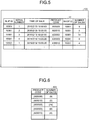
- FIG. 5 is a diagram illustrating an example of a data structure of the processing data.
- the processing data 122 includes the table 10 and not-illustrated other tables. Item names and values corresponding to respective items are set in each table.
- the encoded table 123 is information generated by a generation unit 133 to be described below.
- FIG. 6 is a diagram illustrating an example of a data structure of the encoded table. As described in FIG. 1 , the encoded table 123 is formed by connecting the codes encoded in units of columns. In the encoded table 123, the connected portions of the linked codes function as delimiters. The column separations can thus be determined without decoding the encoded table 123.
- the control unit 130 includes a collection unit 131, an acquisition unit 132, a generation unit 133, and a distribution unit 134.
- the control unit 130 corresponds to an integrated device such as an ASIC (Application Specific Integrated Circuit) and a FPGA (Field Programmable Gate Array).
- the control unit 130 corresponds to an electronic circuit such as a CPU and an MPU (Micro Processing Unit).
- the collection unit 131 is a processing unit that collects the processing data 122 from the collection source system 50 illustrated in FIG. 1 .
- the collection unit 131 stores the collected processing data 122 into the storage unit 120.
- the acquisition unit 132 is a processing unit that obtains the processing procedure definition 121 stored in the storage unit 120.
- the acquisition unit 132 outputs the processing procedure definition 121 to the generation unit 133.
- the generation unit 133 is a processing unit that extracts the table to be processed from the processing data 122 on the basis of the processing procedure definition 121, and generates the encoded table 123 from the table.
- the generation unit 133 refers to the data structure definition file included in the processing procedure definition 121, and identifies items included in the table to be processed.
- the generation unit 133 compares the identified items with the items set in the table of the processing data 122, and extracts a table including all the identified items from the processing data 122.
- the generation unit 133 refers to the data processing definition file included in the processing procedure definition 121, and encodes the columns to be processed, included in the table 10, in units of columns.
- the generation unit 133 connects the encoded columns to generate the encoded table 123.
- Specific processing of the generation unit 133 corresponds to the processing described in FIG. 1 .
- the data processing definition file corresponds to the processing target column information 11 illustrated in FIG. 1 .
- the table extracted as the table to be processed corresponds to the table 10.
- the items "slip ID, serial number, time of sale, product code, shop ID, and number of sales" and values corresponding to the respective items are set in the table 10.
- the values of the columns corresponding to the respective items are separated by delimiters.
- the generation unit 133 scans the columns of the table 10 on the basis of the data processing definition file.
- the generation unit 133 scans the columns of the table 10. If a column to be processed is hit, the generation unit 133 extracts the hit column in units of columns, and encodes the extracted column. For example, the generation unit 133 encodes the column on the basis of a conversion rule that associates the information about columns with codes corresponding to information about the columns. The generation unit 133 repeatedly executes the foregoing processing to encode the columns to be processed in units of columns. The generation unit 133 connects the pieces of encoded information to generate the encoded table 123.
- the generation unit 133 arranges and connects the encoded columns according to a positional relationship of the columns included in the table 10, whereby the encoded table 123 is generated. For example, in the not-encoded table 10, the product code "A00009” and the number of sales "9" are in the same record of the first row. When generating the encoded table 123, the generation unit 133 then arranges and connects the encoded columns "(A00009)” and "(9)” in the record of the first row.
- the distribution unit 134 is a processing unit that transmits the encoded table 123 generated by the generation unit 133 to the distribution destination system 60.
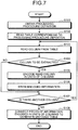
- FIG. 7 is a flowchart illustrating the processing procedure of the encoding apparatus. As illustrated in FIG. 7 , the acquisition unit 132 of the encoding apparatus 100 obtains the processing procedure definition 121 (step S101).
- the generation unit 133 of the encoding apparatus 100 reads a table corresponding to the processing procedure definition 121 from the processing data 122 (step S102).
- the generation unit 133 reads a column from the table (step S103).
- the generation unit 133 determines whether the read column is one to be processed (step S104). If the read column is not one to be processed (step S104, No), the generation unit 133 proceeds to step S107.
- step S104 if the read column is one to be processed (step S104, Yes), the generation unit 133 encodes the read column in units of columns (step S105). The generation unit 133 writes the encoded information (step S106).
- the generation unit 133 determines whether there is another column (step S107). If there is another column (step S107, Yes), the generation unit 133 proceeds to step S103.
- step S107 if there is no other column (step S107, No), the generation unit 133 connects the pieces of information encoded in units of columns to generate the encoded table 123 (step S108).
- the encoding apparatus 100 identifies the columns to be processed from the table 10 in which a plurality of columns are separated by delimiters, and performs encoding in units of columns to generate the encoded table 123. Even in the encoded state, column separations can thus be identified in units of the encoded codes. For example, in the example illustrated in FIG. 1 , the presence of the separation between "(A00009)" and "(9)" can be identified. Encoded information from which column separations can be determined can thus be generated without generating an intermediate file.
- the encoding apparatus 100 scans the plurality of columns included in the table 10, and when a column to be processed is identified, encodes the identified column in units of columns. As compared to the conventional technique in which all the columns to be encoded are extracted before encoding, the encoding can be performed efficiently since the extraction and encoding can be performed concurrently.
- the encoding apparatus 100 arranges the encoded columns according to the positional relationship of the columns included in the table 10, and connects the encoded columns to generate the encoded table 123. If the items of the table 10 and the columns to be processed are known, which column corresponds to which item can thus be determined without decoding the encoded table 123.
- FIG. 8 is a diagram illustrating the example of the computer that executes the encoding program.
- a computer 200 includes a CPU 201 which executes various types of arithmetic processing, an input device 202 which accepts data input from a user, and a display 203.
- the computer 200 also includes a reading device 204 which reads programs and the like from a storage medium, and an interface device 205 which exchanges data with another computer via a network.
- the computer 200 includes a RAM 206 which temporarily stores various types of information, and a hard disk device 207.
- the devices 201 to 207 are connected with a bus 208.
- the hard disk device 207 reads and loads an acquisition program 207a and a generation program 207b into the RAM 206.
- the acquisition program 207a functions as an acquisition process 206a.
- the generation program 207b functions as a generation process 206b.
- the acquisition process 206a corresponds to the acquisition unit 132.
- the generation process 206b corresponds to the generation unit 133.
- the acquisition program 207a and the generation program 207b do not necessarily need to be stored in the hard disk device 207 from the beginning.
- the programs are stored in a "portable physical medium" such as a flexible disk (FD), a CD-ROM, a DVD disk, an optical magnetic disk, and an IC card inserted into the computer 200.
- the computer 200 may read and execute the acquisition program 207a and the generation program 207b.
- Encoded information from which column separations can be determined can be generated without generating an intermediate file.
Landscapes
- Engineering & Computer Science (AREA)
- Theoretical Computer Science (AREA)
- Databases & Information Systems (AREA)
- Data Mining & Analysis (AREA)
- Physics & Mathematics (AREA)
- General Engineering & Computer Science (AREA)
- General Physics & Mathematics (AREA)
- Software Systems (AREA)
- Compression, Expansion, Code Conversion, And Decoders (AREA)
- Information Retrieval, Db Structures And Fs Structures Therefor (AREA)
Abstract
Description
- The embodiment discussed herein is related to an encoding program and the like.
- ETL (Extract/Transform/Load) processing is performed by referring to data existing in a plurality of tables. In referring to a plurality of tables, processing using a dedicated tool and the like is performed. For example, a table is described in a general-purpose file such as csv (Comma-Separated Values) and then compressed by a zip compression format.
- According to a conventional technique, an operation for accepting processing target column information, which specifies columns to be processed, and extracting the columns to be processed from a table is performed before an operation for compressing data on the extracted columns is performed. To obtain a certain compression ratio, the zip compression is performed beyond delimiters indicating column separations.
-
FIG. 9 is a diagram for describing the conventional technique. InFIG. 9 , processing using a table 10 will be described as an example. Items "slip ID, serial number, time of sale, product code, shop ID, and number of sales" and values corresponding to the respective items are set in the table 10. The values of the columns corresponding to the respective items are separated by delimiters. According to the conventional technique, when processingtarget column information 11 is accepted, extracteddata 12 is generated by extracting columns to be processed on the basis of the processingtarget column information 11. - The processing
target column information 11 illustrated inFIG. 9 specifies that the columns of the items "product code" and "number of sales" are extracted. According to the conventional technique,data 10a corresponding to the column of the item "product code" anddata 10b corresponding to the column of the item "number of sales" are extracted from the table 10 to generate extracteddata 12. The pieces of data included in the extracteddata 12 are separated column by column. For example, in the record of the first row of the extracteddata 12, "A00009" and "9" are separated by a delimiter. - According to the conventional technique, if the extracted
data 12 is compressed by zip, the extracteddata 12 is compressed without considering the column separations. Compresseddata 13 is thereby generated.
The compression is thus performed across the columns. For example, "A00009" and "9" are compressed together. - [Patent Literature 1] Japanese Laid-open Patent Publication No.
2014-191593 - [Patent Literature 2] Japanese Laid-open Patent Publication No.
09-204349 - [Patent Literature 3] Japanese Laid-open Patent Publication No.
07-220051 - [Patent Literature 4] Japanese Laid-open Patent Publication No.
2012-256144 - As described in
FIG. 9 , the conventional zip compression is performed beyond delimiters for the sake of compression efficiency. Consequently, for example, thecompressed data 13 itself is difficult to identify column separations. An intermediate decoded file or the like of thecompressed data 13 is therefore generated for the purpose of identifying column separations only, which is inefficient. - Accordingly, it is an object in one aspect of an embodiment of the invention to provide an encoding program, an encoding method, and an encoding apparatus for generating encoded information from which column separations can be determined without generating an intermediate file.
- According to an aspect of an embodiment, an encoding program that causes a computer to execute a process including: obtaining processing target column information for identifying a plurality of processing target columns to be processed among a plurality of columns included in a table in which the plurality of columns are separated by separation information; encoding the plurality of processing target columns of the table in units of columns by using the processing target column information; and generating an encoded table in which the plurality of encoded processing target columns are connected.
-
-
FIG. 1 is a diagram for describing processing of an encoding apparatus according to an embodiment; -
FIG. 2 is a diagram illustrating a configuration of a system according to the present embodiment; -
FIG. 3 is a functional block diagram illustrating a configuration of an encoding apparatus according to the present embodiment; -
FIG. 4 is a diagram illustrating an example of a data structure of a data processing definition file; -
FIG. 5 is a diagram illustrating an example of a data structure of processing data; -
FIG. 6 is a diagram illustrating an example of a data structure of an encoded table; -
FIG. 7 is a flowchart illustrating a processing procedure of the encoding apparatus; -
FIG. 8 is a diagram illustrating an example of a computer executing an encoding program; and -
FIG. 9 is a diagram for describing a conventional technique. - According to the foregoing conventional technique, there is a problem that column separations are not identifiable unless the encoded information is once converted into an intermediate file.
- Preferred embodiments of the present invention will be explained with reference to accompanying drawings. The present invention is not limited by this embodiment.
-
FIG. 1 is a diagram for describing processing of an encoding apparatus according to the present embodiment. InFIG. 1 , a description will be given by using a table 10 as an example. Items "slip ID, serial number, time of sale, product code, shop ID, and number of sales" and values corresponding to the respective items are set in the table 10. The values of the columns corresponding to the respective items are separated by delimiters. When the encoding apparatus accepts processingtarget column information 11, the encoding apparatus scans the columns of the table 10 on the basis of the processingtarget column information 11. - If the encoding apparatus scans the columns of the table 10 and hits a column to be processed, the encoding apparatus extracts the hit column in units of columns, and encodes the extracted column. The encoding apparatus repeatedly executes the foregoing processing to encode columns to be processed in units of columns, and connects the pieces of encoded information to generate an encoded table 123.
- The processing
target column information 11 illustrated inFIG. 1 specifies that the columns of the items "product code" and "number of sales" are extracted. When the encoding apparatus scans the columns in the record of the first row of the table 10, "A00009" and "9" are hit as columns to be processed. The encoding apparatus then encodes "A00009" into "(A00009)" and "9" into "(9)". For convenience of description, in the present embodiment, information about an encoded column will be parenthesized. - When the encoding apparatus scans the columns in the record of the second row of the table 10, "A00015" and "5" are hit as columns to be processed. The encoding apparatus then encodes "A00015" into "(A00015)" and "5" into "(5)". When the encoding apparatus scans the columns in the record of the third row of the table 10, "A00003" and "14" are hit as columns to be processed. The encoding apparatus then encodes "A00003" into "(A00003)" and "14" into "(14)".
- When the encoding apparatus scans the columns in the record of the fourth row of the table 10, "A00003" and "9" are hit as columns to be processed. The encoding apparatus then encodes "A00003" into "(A00003)" and "9" into "(9)". When the encoding apparatus scans the columns in the record of the fifth row of the table 10, "A00015" and "4" are hit as columns to be processed. The encoding apparatus then encodes "A00015" into "(A00015)" and "4" into "(4)".
- The encoding apparatus connects the pieces of encoded information to generate the encoded table 123 illustrated in
FIG. 1 . - As described above, the encoding apparatus generates the encoded table 123 by identifying the columns to be processed from the table 10 in which a plurality of columns are separated by delimiters, and encodes the columns to be processed in units of columns. Even in the encoded state, column separations can thus be identified in units of pieces of encoded data. For example, in the example illustrated in
FIG. 1 , the presence of the separation between "(A00009)" and "(9)" can be determined. Encoded information in which column separations can be identified can thus be generated without generating an intermediate file. - Next, an example of a configuration of a system according to the present embodiment will be described.
FIG. 2 is a diagram illustrating the configuration of the system according to the present embodiment. As illustrated inFIG. 2 , the system includes acollection source system 50, adistribution destination system 60, and anencoding apparatus 100. Theencoding apparatus 100 is connected to thecollection source system 50 and thedistribution destination system 60 via a network and the like. - The
collection source system 50 is a system that collects information to be processed, such as the table 10 described inFIG. 1 . In the following description, the information to be processed, collected by thecollection source system 50 will be referred to as processing data. Thecollection source system 50 transmits the processing data to theencoding apparatus 100. - The
distribution destination system 60 is a system that receives an encoded table 123 output from theencoding apparatus 100 and performs various types of processing. - The
encoding apparatus 100 is an apparatus that identifies columns to be processed from the table 10 in which a plurality of columns are separated by delimiters, and encodes the columns to be processed in units of columns to generate the encoded table 123. For example, the table 10 is included in the processing data transmitted from thecollection source system 50. Theencoding apparatus 100 distributes the encoded table 123 to thedistribution destination system 60. -
FIG. 3 is a functional block diagram illustrating a configuration of the encoding apparatus according to the present embodiment. As illustrated inFIG. 3 , theencoding apparatus 100 includes acommunication unit 110, astorage unit 120, and acontrol unit 130. - The
communication unit 110 is a processing unit that performs data communication with thecollection source system 50 and thedistribution destination system 60 via the network. Thecontrol unit 130 to be described later exchanges data with thecollection source system 50 and thedistribution destination system 60 via thecommunication unit 110. Thecommunication unit 110 corresponds to a communication apparatus. - The
storage unit 120 includes aprocessing procedure definition 121,processing data 122, and the encoded table 123. Thestorage unit 120 corresponds to a semiconductor memory element such as a RAM (Random Access Memory), a ROM (Read Only Memory), and a flash memory. Alternatively, thestorage unit 120 corresponds to a storage device such as a hard disk and an optical disk. - The
processing procedure definition 121 is information that defines information about the table to be processed and information about the columns to be processed (processing target column information 11). Theprocessing procedure definition 121 is information including a data structure definition file and a data processing definition file. Theprocessing procedure definition 121 is generated in advance by an administrator and the like. - The data structure definition file is a file in which table information about data to be processed is stored. The table information is specified by item names. For example, if the item names indicated by the table information are "slip ID, serial number, time of sale, product code, shop ID, and number of sales", the table 10 described in
FIG. 1 is the table to be processed. - The data processing definition file is information corresponding to the processing
target column information 11 described inFIG. 1 .FIG. 4 is a diagram illustrating an example of a data structure of the data processing definition file. As illustrated inFIG. 4 , the data processing definition file defines each data conversion process in anarea 70a. For example, if a data conversion process such as connection and column extraction is performed, "Replace" is set in thearea 70a. - Definition information about input data for data extraction is set in an
area 70b. The item names (columns) of the table to be processed are defined by ID names, and used in the processing described in an area 70c. - Definition information about output data (encoded table 123) is set in the area 70c. The item names of the columns to be processed are specified in the area 70c. In the example illustrated in
FIG. 4 , the item names of the columns to be processed are defined as "product code" and "number of sales". - The
processing data 122 is information generated by thecollection source system 50.FIG. 5 is a diagram illustrating an example of a data structure of the processing data. For example, theprocessing data 122 includes the table 10 and not-illustrated other tables. Item names and values corresponding to respective items are set in each table. - The encoded table 123 is information generated by a
generation unit 133 to be described below.FIG. 6 is a diagram illustrating an example of a data structure of the encoded table. As described inFIG. 1 , the encoded table 123 is formed by connecting the codes encoded in units of columns. In the encoded table 123, the connected portions of the linked codes function as delimiters. The column separations can thus be determined without decoding the encoded table 123. - The
control unit 130 includes acollection unit 131, anacquisition unit 132, ageneration unit 133, and adistribution unit 134. Thecontrol unit 130 corresponds to an integrated device such as an ASIC (Application Specific Integrated Circuit) and a FPGA (Field Programmable Gate Array). Alternatively, thecontrol unit 130 corresponds to an electronic circuit such as a CPU and an MPU (Micro Processing Unit). - The
collection unit 131 is a processing unit that collects theprocessing data 122 from thecollection source system 50 illustrated inFIG. 1 . Thecollection unit 131 stores the collectedprocessing data 122 into thestorage unit 120. - The
acquisition unit 132 is a processing unit that obtains theprocessing procedure definition 121 stored in thestorage unit 120. Theacquisition unit 132 outputs theprocessing procedure definition 121 to thegeneration unit 133. - The
generation unit 133 is a processing unit that extracts the table to be processed from theprocessing data 122 on the basis of theprocessing procedure definition 121, and generates the encoded table 123 from the table. - An example of processing by which the
generation unit 133 extracts the table to be processed from theprocessing data 122 will be described. Thegeneration unit 133 refers to the data structure definition file included in theprocessing procedure definition 121, and identifies items included in the table to be processed. Thegeneration unit 133 compares the identified items with the items set in the table of theprocessing data 122, and extracts a table including all the identified items from theprocessing data 122. - An example of processing by which the
generation unit 133 generates the encoded table 123 on the basis of the extracted table will be described. Thegeneration unit 133 refers to the data processing definition file included in theprocessing procedure definition 121, and encodes the columns to be processed, included in the table 10, in units of columns. Thegeneration unit 133 connects the encoded columns to generate the encoded table 123. - Specific processing of the
generation unit 133 corresponds to the processing described inFIG. 1 . The data processing definition file corresponds to the processingtarget column information 11 illustrated inFIG. 1 . The table extracted as the table to be processed corresponds to the table 10. - For example, the items "slip ID, serial number, time of sale, product code, shop ID, and number of sales" and values corresponding to the respective items are set in the table 10. The values of the columns corresponding to the respective items are separated by delimiters. The
generation unit 133 scans the columns of the table 10 on the basis of the data processing definition file. - The
generation unit 133 scans the columns of the table 10. If a column to be processed is hit, thegeneration unit 133 extracts the hit column in units of columns, and encodes the extracted column. For example, thegeneration unit 133 encodes the column on the basis of a conversion rule that associates the information about columns with codes corresponding to information about the columns. Thegeneration unit 133 repeatedly executes the foregoing processing to encode the columns to be processed in units of columns. Thegeneration unit 133 connects the pieces of encoded information to generate the encoded table 123. - The
generation unit 133 arranges and connects the encoded columns according to a positional relationship of the columns included in the table 10, whereby the encoded table 123 is generated. For example, in the not-encoded table 10, the product code "A00009" and the number of sales "9" are in the same record of the first row. When generating the encoded table 123, thegeneration unit 133 then arranges and connects the encoded columns "(A00009)" and "(9)" in the record of the first row. - The
distribution unit 134 is a processing unit that transmits the encoded table 123 generated by thegeneration unit 133 to thedistribution destination system 60. - Next, an example of the processing procedure of the
encoding apparatus 100 according to the present embodiment will be described.FIG. 7 is a flowchart illustrating the processing procedure of the encoding apparatus. As illustrated inFIG. 7 , theacquisition unit 132 of theencoding apparatus 100 obtains the processing procedure definition 121 (step S101). - The
generation unit 133 of theencoding apparatus 100 reads a table corresponding to theprocessing procedure definition 121 from the processing data 122 (step S102). Thegeneration unit 133 reads a column from the table (step S103). - The
generation unit 133 determines whether the read column is one to be processed (step S104). If the read column is not one to be processed (step S104, No), thegeneration unit 133 proceeds to step S107. - On the other hand, if the read column is one to be processed (step S104, Yes), the
generation unit 133 encodes the read column in units of columns (step S105). Thegeneration unit 133 writes the encoded information (step S106). - The
generation unit 133 determines whether there is another column (step S107). If there is another column (step S107, Yes), thegeneration unit 133 proceeds to step S103. - On the other hand, if there is no other column (step S107, No), the
generation unit 133 connects the pieces of information encoded in units of columns to generate the encoded table 123 (step S108). - Next, an effect of the
encoding apparatus 100 according to the present embodiment will be described. Theencoding apparatus 100 identifies the columns to be processed from the table 10 in which a plurality of columns are separated by delimiters, and performs encoding in units of columns to generate the encoded table 123. Even in the encoded state, column separations can thus be identified in units of the encoded codes. For example, in the example illustrated inFIG. 1 , the presence of the separation between "(A00009)" and "(9)" can be identified. Encoded information from which column separations can be determined can thus be generated without generating an intermediate file. - The
encoding apparatus 100 scans the plurality of columns included in the table 10, and when a column to be processed is identified, encodes the identified column in units of columns. As compared to the conventional technique in which all the columns to be encoded are extracted before encoding, the encoding can be performed efficiently since the extraction and encoding can be performed concurrently. - The
encoding apparatus 100 arranges the encoded columns according to the positional relationship of the columns included in the table 10, and connects the encoded columns to generate the encoded table 123. If the items of the table 10 and the columns to be processed are known, which column corresponds to which item can thus be determined without decoding the encoded table 123. - Next, an example of a computer that executes an encoding program for implementing functions similar to those of the
encoding apparatus 100 described in the foregoing embodiment will be described.FIG. 8 is a diagram illustrating the example of the computer that executes the encoding program. - As illustrated in
FIG. 8 , acomputer 200 includes aCPU 201 which executes various types of arithmetic processing, aninput device 202 which accepts data input from a user, and adisplay 203. Thecomputer 200 also includes areading device 204 which reads programs and the like from a storage medium, and aninterface device 205 which exchanges data with another computer via a network. Thecomputer 200 includes aRAM 206 which temporarily stores various types of information, and ahard disk device 207. Thedevices 201 to 207 are connected with a bus 208. - The
hard disk device 207 reads and loads anacquisition program 207a and ageneration program 207b into theRAM 206. Theacquisition program 207a functions as anacquisition process 206a. Thegeneration program 207b functions as ageneration process 206b. For example, theacquisition process 206a corresponds to theacquisition unit 132. Thegeneration process 206b corresponds to thegeneration unit 133. - The
acquisition program 207a and thegeneration program 207b do not necessarily need to be stored in thehard disk device 207 from the beginning. For examples, the programs are stored in a "portable physical medium" such as a flexible disk (FD), a CD-ROM, a DVD disk, an optical magnetic disk, and an IC card inserted into thecomputer 200. Thecomputer 200 may read and execute theacquisition program 207a and thegeneration program 207b. - Encoded information from which column separations can be determined can be generated without generating an intermediate file.
Claims (9)
- An encoding program that causes a computer to execute a process comprising:obtaining processing target column information for identifying a plurality of processing target columns to be processed among a plurality of columns included in a table in which the plurality of columns are separated by separation information;encoding the plurality of processing target columns of the table in units of columns by using the processing target column information; andgenerating an encoded table in which the plurality of encoded processing target columns are connected.
- The encoding program according to claim 1, wherein the encoding includes scanning a plurality of columns included in the table, and encoding an identified processing target column in units of columns when the processing target column is identified.
- The encoding program according to claim 1 or 2, wherein the generating of the encoded table includes arranging the encoded processing target columns according to a positional relationship of columns included in the table, and connecting the encoded processing target columns to generate the encoded table.
- An encoding method comprising:obtaining processing target column information for identifying a plurality of processing target columns to be processed among a plurality of columns included in a table in which the plurality of columns are separated by separation information;encoding the plurality of processing target columns of the table in units of columns by using the processing target column information; andgenerating an encoded table in which the plurality of encoded processing target columns are connected.
- The encoding method according to claim 4, wherein the encoding includes scanning a plurality of columns included in the table, and encoding an identified processing target column in units of columns when the processing target column is identified.
- The encoding method according to claim 4 or 5, wherein the generating of the encoded table includes arranging the encoded processing target columns according to a positional relationship of columns included in the table, and connecting the encoded processing target columns to generate the encoded table.
- An encoding apparatus comprising:an acquisition unit (132) that obtains processing target column information for identifying a plurality of processing target columns to be processed among a plurality of columns included in a table in which the plurality of columns are separated by separation information; anda generation unit (133) that encodes the plurality of processing target columns of the table in units of columns by using the processing target column information, and generates an encoded table in which the plurality of encoded processing target columns are connected.
- The encoding apparatus according to claim 7, wherein the generation unit (133) scans a plurality of columns included in the table, and encodes an identified processing target column in units of columns when the processing target column is identified.
- The encoding apparatus according to claim 7 or 8, wherein the generation unit (133) arranges the encoded processing target columns according to a positional relationship of columns included in the table, and connects the encoded processing target columns to generate the encoded table.
Applications Claiming Priority (1)
| Application Number | Priority Date | Filing Date | Title |
|---|---|---|---|
| JP2016198915A JP6733483B2 (en) | 2016-10-07 | 2016-10-07 | Encoding program, encoding method, and encoding device |
Publications (2)
| Publication Number | Publication Date |
|---|---|
| EP3306496A1 true EP3306496A1 (en) | 2018-04-11 |
| EP3306496B1 EP3306496B1 (en) | 2021-03-24 |
Family
ID=59683420
Family Applications (1)
| Application Number | Title | Priority Date | Filing Date |
|---|---|---|---|
| EP17186618.9A Not-in-force EP3306496B1 (en) | 2016-10-07 | 2017-08-17 | Encoding program, encoding method, and encoding apparatus |
Country Status (3)
| Country | Link |
|---|---|
| US (1) | US20180101566A1 (en) |
| EP (1) | EP3306496B1 (en) |
| JP (1) | JP6733483B2 (en) |
Citations (5)
| Publication number | Priority date | Publication date | Assignee | Title |
|---|---|---|---|---|
| JPH07220051A (en) | 1994-02-08 | 1995-08-18 | Hitachi Ltd | Image data conversion system |
| JPH09204349A (en) | 1996-01-25 | 1997-08-05 | Fujitsu Ltd | Information display system, information providing device, and information display device |
| EP2040180A1 (en) * | 2007-09-24 | 2009-03-25 | Hasso-Plattner-Institut für Softwaresystemtechnik GmbH | ETL-less zero-redundancy system and method for reporting OLTP data |
| JP2012256144A (en) | 2011-06-08 | 2012-12-27 | Jfe Systems Inc | Data management storage system |
| JP2014191593A (en) | 2013-03-27 | 2014-10-06 | Nec Corp | Column store type database management system |
Family Cites Families (8)
| Publication number | Priority date | Publication date | Assignee | Title |
|---|---|---|---|---|
| US6996589B1 (en) * | 2002-01-16 | 2006-02-07 | Convergys Cmg Utah, Inc. | System and method for database conversion |
| US8108361B2 (en) * | 2008-07-31 | 2012-01-31 | Microsoft Corporation | Efficient column based data encoding for large-scale data storage |
| JP5549177B2 (en) * | 2009-10-22 | 2014-07-16 | 富士通株式会社 | Compression program, method and apparatus, and decompression program, method and apparatus |
| US8762875B2 (en) * | 2011-12-23 | 2014-06-24 | Blackberry Limited | Posting activity visualization |
| KR101522870B1 (en) * | 2013-10-01 | 2015-05-26 | 주식회사 파수닷컴 | Apparatus and method for encrypting data column |
| US20170039470A1 (en) * | 2013-12-25 | 2017-02-09 | Hitachi, Ltd. | Factor extraction system and factor extraction method |
| US10067909B2 (en) * | 2014-06-25 | 2018-09-04 | Sap Se | Sparse linear algebra in column-oriented in-memory database |
| US9430554B2 (en) * | 2014-08-28 | 2016-08-30 | Weebly, Inc. | Object-relational mapping based on virtual columns |
-
2016
- 2016-10-07 JP JP2016198915A patent/JP6733483B2/en not_active Expired - Fee Related
-
2017
- 2017-08-17 EP EP17186618.9A patent/EP3306496B1/en not_active Not-in-force
- 2017-08-18 US US15/680,319 patent/US20180101566A1/en not_active Abandoned
Patent Citations (5)
| Publication number | Priority date | Publication date | Assignee | Title |
|---|---|---|---|---|
| JPH07220051A (en) | 1994-02-08 | 1995-08-18 | Hitachi Ltd | Image data conversion system |
| JPH09204349A (en) | 1996-01-25 | 1997-08-05 | Fujitsu Ltd | Information display system, information providing device, and information display device |
| EP2040180A1 (en) * | 2007-09-24 | 2009-03-25 | Hasso-Plattner-Institut für Softwaresystemtechnik GmbH | ETL-less zero-redundancy system and method for reporting OLTP data |
| JP2012256144A (en) | 2011-06-08 | 2012-12-27 | Jfe Systems Inc | Data management storage system |
| JP2014191593A (en) | 2013-03-27 | 2014-10-06 | Nec Corp | Column store type database management system |
Non-Patent Citations (2)
| Title |
|---|
| GRAEFE G ET AL: "Data compression and database performance", APPLIED COMPUTING, 1991., ÝPROCEEDINGS OF THE 1991 SYMPOSIUM ON KANSAS CITY, MO, USA 3-5 APRIL 1, LOS ALAMITOS, CA, USA,IEEE COMPUT. SOC, US, 3 April 1991 (1991-04-03), pages 22 - 27, XP010022657, ISBN: 978-0-8186-2136-9, DOI: 10.1109/SOAC.1991.143840 * |
| VIJAYSHANKAR RAMAN ET AL: "How to Wring a Table Dry: Entropy Compression of Relations and Querying of Compressed Relations", VLDB '06: PROCEEDINGS OF THE 32ND INTERNATIONAL CONFERENCE ON VERY LARGE DATA BASES, 12 September 2006 (2006-09-12), pages 858 - 869, XP055039042, Retrieved from the Internet <URL:http://delivery.acm.org/10.1145/1170000/1164201/p858-raman.pdf?ip=145.64.134.241&acc=ACTIVE SERVICE&CFID=162939112&CFTOKEN=39118953&__acm__=1348501251_4a3e63a8ff50321a2c257e1607311aec> [retrieved on 20120924] * |
Also Published As
| Publication number | Publication date |
|---|---|
| JP2018060444A (en) | 2018-04-12 |
| JP6733483B2 (en) | 2020-07-29 |
| US20180101566A1 (en) | 2018-04-12 |
| EP3306496B1 (en) | 2021-03-24 |
Similar Documents
| Publication | Publication Date | Title |
|---|---|---|
| US9471412B2 (en) | Encoding diagnostic data in an error message for a computer program | |
| CN102683149B (en) | Mass analysis data processing method and mass analysis data treatment system | |
| JP2014041486A5 (en) | ||
| CN104765717A (en) | Method and device for mass document format conversion | |
| JP2014219775A (en) | Bar-code symbol reader and bar-code symbol reading method | |
| JP2023501093A (en) | Customizable delimited text compression framework | |
| Qiu et al. | A new approach to multimedia files carving | |
| TWI544419B (en) | Encoding method and decoding method for two-dimensional barcode, and electronic device | |
| JP7255841B2 (en) | Information processing device, information processing system, control method, and program | |
| JP6955676B2 (en) | Log analysis method, system and recording medium | |
| RU2013137742A (en) | COMPRESSING AND RESTORING IMAGES WITH DEPTH USING DEPTH AND AMPLITUDE DATA | |
| EP3306496B1 (en) | Encoding program, encoding method, and encoding apparatus | |
| WO2018106524A1 (en) | Feature detection in compressive imaging | |
| CN113570677A (en) | Image compression method and device | |
| CN112035169B (en) | Jump processing method and device, computer equipment and computer readable storage medium | |
| JP2013214159A (en) | Log management method, log management system, and information processing apparatus | |
| JP2006100973A (en) | Data compression device and data decompression device | |
| CN112835969A (en) | A method for statistical analysis of ETL circulation data | |
| CN114090565A (en) | Map data processing method and device of sweeper, storage medium and electronic equipment | |
| US10367523B2 (en) | Data processing method and data processing apparatus | |
| KR101541869B1 (en) | Method for encoding and decoding using variable length coding and system thereof | |
| JP5626440B2 (en) | Method and apparatus for encoding / decoding numeric data string | |
| KR20180038812A (en) | Creating And Reading Method of Combination Barcode Containing Plural Coupon Information And Application Of Thereof | |
| JP2001169120A5 (en) | ||
| KR101661646B1 (en) | Webpage service system and method using image code |
Legal Events
| Date | Code | Title | Description |
|---|---|---|---|
| PUAI | Public reference made under article 153(3) epc to a published international application that has entered the european phase |
Free format text: ORIGINAL CODE: 0009012 |
|
| STAA | Information on the status of an ep patent application or granted ep patent |
Free format text: STATUS: THE APPLICATION HAS BEEN PUBLISHED |
|
| AK | Designated contracting states |
Kind code of ref document: A1 Designated state(s): AL AT BE BG CH CY CZ DE DK EE ES FI FR GB GR HR HU IE IS IT LI LT LU LV MC MK MT NL NO PL PT RO RS SE SI SK SM TR |
|
| AX | Request for extension of the european patent |
Extension state: BA ME |
|
| STAA | Information on the status of an ep patent application or granted ep patent |
Free format text: STATUS: REQUEST FOR EXAMINATION WAS MADE |
|
| 17P | Request for examination filed |
Effective date: 20180921 |
|
| RBV | Designated contracting states (corrected) |
Designated state(s): AL AT BE BG CH CY CZ DE DK EE ES FI FR GB GR HR HU IE IS IT LI LT LU LV MC MK MT NL NO PL PT RO RS SE SI SK SM TR |
|
| REG | Reference to a national code |
Ref country code: DE Ref legal event code: R079 Ref document number: 602017035103 Country of ref document: DE Free format text: PREVIOUS MAIN CLASS: G06F0017300000 Ipc: G06F0016250000 |
|
| GRAP | Despatch of communication of intention to grant a patent |
Free format text: ORIGINAL CODE: EPIDOSNIGR1 |
|
| STAA | Information on the status of an ep patent application or granted ep patent |
Free format text: STATUS: GRANT OF PATENT IS INTENDED |
|
| RIC1 | Information provided on ipc code assigned before grant |
Ipc: G06F 16/25 20190101AFI20201026BHEP Ipc: G06F 16/22 20190101ALI20201026BHEP |
|
| INTG | Intention to grant announced |
Effective date: 20201127 |
|
| GRAS | Grant fee paid |
Free format text: ORIGINAL CODE: EPIDOSNIGR3 |
|
| GRAA | (expected) grant |
Free format text: ORIGINAL CODE: 0009210 |
|
| STAA | Information on the status of an ep patent application or granted ep patent |
Free format text: STATUS: THE PATENT HAS BEEN GRANTED |
|
| AK | Designated contracting states |
Kind code of ref document: B1 Designated state(s): AL AT BE BG CH CY CZ DE DK EE ES FI FR GB GR HR HU IE IS IT LI LT LU LV MC MK MT NL NO PL PT RO RS SE SI SK SM TR |
|
| REG | Reference to a national code |
Ref country code: GB Ref legal event code: FG4D |
|
| REG | Reference to a national code |
Ref country code: CH Ref legal event code: EP |
|
| REG | Reference to a national code |
Ref country code: DE Ref legal event code: R096 Ref document number: 602017035103 Country of ref document: DE |
|
| REG | Reference to a national code |
Ref country code: IE Ref legal event code: FG4D |
|
| REG | Reference to a national code |
Ref country code: AT Ref legal event code: REF Ref document number: 1375197 Country of ref document: AT Kind code of ref document: T Effective date: 20210415 |
|
| REG | Reference to a national code |
Ref country code: LT Ref legal event code: MG9D |
|
| PG25 | Lapsed in a contracting state [announced via postgrant information from national office to epo] |
Ref country code: NO Free format text: LAPSE BECAUSE OF FAILURE TO SUBMIT A TRANSLATION OF THE DESCRIPTION OR TO PAY THE FEE WITHIN THE PRESCRIBED TIME-LIMIT Effective date: 20210624 Ref country code: GR Free format text: LAPSE BECAUSE OF FAILURE TO SUBMIT A TRANSLATION OF THE DESCRIPTION OR TO PAY THE FEE WITHIN THE PRESCRIBED TIME-LIMIT Effective date: 20210625 Ref country code: HR Free format text: LAPSE BECAUSE OF FAILURE TO SUBMIT A TRANSLATION OF THE DESCRIPTION OR TO PAY THE FEE WITHIN THE PRESCRIBED TIME-LIMIT Effective date: 20210324 Ref country code: FI Free format text: LAPSE BECAUSE OF FAILURE TO SUBMIT A TRANSLATION OF THE DESCRIPTION OR TO PAY THE FEE WITHIN THE PRESCRIBED TIME-LIMIT Effective date: 20210324 Ref country code: BG Free format text: LAPSE BECAUSE OF FAILURE TO SUBMIT A TRANSLATION OF THE DESCRIPTION OR TO PAY THE FEE WITHIN THE PRESCRIBED TIME-LIMIT Effective date: 20210624 |
|
| PGFP | Annual fee paid to national office [announced via postgrant information from national office to epo] |
Ref country code: FR Payment date: 20210527 Year of fee payment: 5 |
|
| PG25 | Lapsed in a contracting state [announced via postgrant information from national office to epo] |
Ref country code: RS Free format text: LAPSE BECAUSE OF FAILURE TO SUBMIT A TRANSLATION OF THE DESCRIPTION OR TO PAY THE FEE WITHIN THE PRESCRIBED TIME-LIMIT Effective date: 20210324 Ref country code: LV Free format text: LAPSE BECAUSE OF FAILURE TO SUBMIT A TRANSLATION OF THE DESCRIPTION OR TO PAY THE FEE WITHIN THE PRESCRIBED TIME-LIMIT Effective date: 20210324 Ref country code: SE Free format text: LAPSE BECAUSE OF FAILURE TO SUBMIT A TRANSLATION OF THE DESCRIPTION OR TO PAY THE FEE WITHIN THE PRESCRIBED TIME-LIMIT Effective date: 20210324 |
|
| PGFP | Annual fee paid to national office [announced via postgrant information from national office to epo] |
Ref country code: GB Payment date: 20210610 Year of fee payment: 5 |
|
| REG | Reference to a national code |
Ref country code: NL Ref legal event code: MP Effective date: 20210324 |
|
| REG | Reference to a national code |
Ref country code: AT Ref legal event code: MK05 Ref document number: 1375197 Country of ref document: AT Kind code of ref document: T Effective date: 20210324 |
|
| PG25 | Lapsed in a contracting state [announced via postgrant information from national office to epo] |
Ref country code: NL Free format text: LAPSE BECAUSE OF FAILURE TO SUBMIT A TRANSLATION OF THE DESCRIPTION OR TO PAY THE FEE WITHIN THE PRESCRIBED TIME-LIMIT Effective date: 20210324 |
|
| PG25 | Lapsed in a contracting state [announced via postgrant information from national office to epo] |
Ref country code: AT Free format text: LAPSE BECAUSE OF FAILURE TO SUBMIT A TRANSLATION OF THE DESCRIPTION OR TO PAY THE FEE WITHIN THE PRESCRIBED TIME-LIMIT Effective date: 20210324 Ref country code: SM Free format text: LAPSE BECAUSE OF FAILURE TO SUBMIT A TRANSLATION OF THE DESCRIPTION OR TO PAY THE FEE WITHIN THE PRESCRIBED TIME-LIMIT Effective date: 20210324 Ref country code: CZ Free format text: LAPSE BECAUSE OF FAILURE TO SUBMIT A TRANSLATION OF THE DESCRIPTION OR TO PAY THE FEE WITHIN THE PRESCRIBED TIME-LIMIT Effective date: 20210324 Ref country code: EE Free format text: LAPSE BECAUSE OF FAILURE TO SUBMIT A TRANSLATION OF THE DESCRIPTION OR TO PAY THE FEE WITHIN THE PRESCRIBED TIME-LIMIT Effective date: 20210324 Ref country code: LT Free format text: LAPSE BECAUSE OF FAILURE TO SUBMIT A TRANSLATION OF THE DESCRIPTION OR TO PAY THE FEE WITHIN THE PRESCRIBED TIME-LIMIT Effective date: 20210324 |
|
| PG25 | Lapsed in a contracting state [announced via postgrant information from national office to epo] |
Ref country code: IS Free format text: LAPSE BECAUSE OF FAILURE TO SUBMIT A TRANSLATION OF THE DESCRIPTION OR TO PAY THE FEE WITHIN THE PRESCRIBED TIME-LIMIT Effective date: 20210724 Ref country code: PT Free format text: LAPSE BECAUSE OF FAILURE TO SUBMIT A TRANSLATION OF THE DESCRIPTION OR TO PAY THE FEE WITHIN THE PRESCRIBED TIME-LIMIT Effective date: 20210726 Ref country code: PL Free format text: LAPSE BECAUSE OF FAILURE TO SUBMIT A TRANSLATION OF THE DESCRIPTION OR TO PAY THE FEE WITHIN THE PRESCRIBED TIME-LIMIT Effective date: 20210324 Ref country code: RO Free format text: LAPSE BECAUSE OF FAILURE TO SUBMIT A TRANSLATION OF THE DESCRIPTION OR TO PAY THE FEE WITHIN THE PRESCRIBED TIME-LIMIT Effective date: 20210324 Ref country code: SK Free format text: LAPSE BECAUSE OF FAILURE TO SUBMIT A TRANSLATION OF THE DESCRIPTION OR TO PAY THE FEE WITHIN THE PRESCRIBED TIME-LIMIT Effective date: 20210324 |
|
| PGFP | Annual fee paid to national office [announced via postgrant information from national office to epo] |
Ref country code: DE Payment date: 20210528 Year of fee payment: 5 |
|
| REG | Reference to a national code |
Ref country code: DE Ref legal event code: R097 Ref document number: 602017035103 Country of ref document: DE |
|
| PG25 | Lapsed in a contracting state [announced via postgrant information from national office to epo] |
Ref country code: ES Free format text: LAPSE BECAUSE OF FAILURE TO SUBMIT A TRANSLATION OF THE DESCRIPTION OR TO PAY THE FEE WITHIN THE PRESCRIBED TIME-LIMIT Effective date: 20210324 Ref country code: DK Free format text: LAPSE BECAUSE OF FAILURE TO SUBMIT A TRANSLATION OF THE DESCRIPTION OR TO PAY THE FEE WITHIN THE PRESCRIBED TIME-LIMIT Effective date: 20210324 Ref country code: AL Free format text: LAPSE BECAUSE OF FAILURE TO SUBMIT A TRANSLATION OF THE DESCRIPTION OR TO PAY THE FEE WITHIN THE PRESCRIBED TIME-LIMIT Effective date: 20210324 |
|
| PLBE | No opposition filed within time limit |
Free format text: ORIGINAL CODE: 0009261 |
|
| STAA | Information on the status of an ep patent application or granted ep patent |
Free format text: STATUS: NO OPPOSITION FILED WITHIN TIME LIMIT |
|
| PG25 | Lapsed in a contracting state [announced via postgrant information from national office to epo] |
Ref country code: SI Free format text: LAPSE BECAUSE OF FAILURE TO SUBMIT A TRANSLATION OF THE DESCRIPTION OR TO PAY THE FEE WITHIN THE PRESCRIBED TIME-LIMIT Effective date: 20210324 |
|
| 26N | No opposition filed |
Effective date: 20220104 |
|
| REG | Reference to a national code |
Ref country code: CH Ref legal event code: PL |
|
| PG25 | Lapsed in a contracting state [announced via postgrant information from national office to epo] |
Ref country code: MC Free format text: LAPSE BECAUSE OF FAILURE TO SUBMIT A TRANSLATION OF THE DESCRIPTION OR TO PAY THE FEE WITHIN THE PRESCRIBED TIME-LIMIT Effective date: 20210324 |
|
| REG | Reference to a national code |
Ref country code: BE Ref legal event code: MM Effective date: 20210831 |
|
| PG25 | Lapsed in a contracting state [announced via postgrant information from national office to epo] |
Ref country code: LI Free format text: LAPSE BECAUSE OF NON-PAYMENT OF DUE FEES Effective date: 20210831 Ref country code: CH Free format text: LAPSE BECAUSE OF NON-PAYMENT OF DUE FEES Effective date: 20210831 |
|
| PG25 | Lapsed in a contracting state [announced via postgrant information from national office to epo] |
Ref country code: IS Free format text: LAPSE BECAUSE OF FAILURE TO SUBMIT A TRANSLATION OF THE DESCRIPTION OR TO PAY THE FEE WITHIN THE PRESCRIBED TIME-LIMIT Effective date: 20210724 Ref country code: LU Free format text: LAPSE BECAUSE OF NON-PAYMENT OF DUE FEES Effective date: 20210817 |
|
| PG25 | Lapsed in a contracting state [announced via postgrant information from national office to epo] |
Ref country code: IE Free format text: LAPSE BECAUSE OF NON-PAYMENT OF DUE FEES Effective date: 20210817 Ref country code: BE Free format text: LAPSE BECAUSE OF NON-PAYMENT OF DUE FEES Effective date: 20210831 |
|
| PG25 | Lapsed in a contracting state [announced via postgrant information from national office to epo] |
Ref country code: IT Free format text: LAPSE BECAUSE OF FAILURE TO SUBMIT A TRANSLATION OF THE DESCRIPTION OR TO PAY THE FEE WITHIN THE PRESCRIBED TIME-LIMIT Effective date: 20210324 |
|
| REG | Reference to a national code |
Ref country code: DE Ref legal event code: R119 Ref document number: 602017035103 Country of ref document: DE |
|
| GBPC | Gb: european patent ceased through non-payment of renewal fee |
Effective date: 20220817 |
|
| PG25 | Lapsed in a contracting state [announced via postgrant information from national office to epo] |
Ref country code: HU Free format text: LAPSE BECAUSE OF FAILURE TO SUBMIT A TRANSLATION OF THE DESCRIPTION OR TO PAY THE FEE WITHIN THE PRESCRIBED TIME-LIMIT; INVALID AB INITIO Effective date: 20170817 |
|
| PG25 | Lapsed in a contracting state [announced via postgrant information from national office to epo] |
Ref country code: CY Free format text: LAPSE BECAUSE OF FAILURE TO SUBMIT A TRANSLATION OF THE DESCRIPTION OR TO PAY THE FEE WITHIN THE PRESCRIBED TIME-LIMIT Effective date: 20210324 |
|
| PG25 | Lapsed in a contracting state [announced via postgrant information from national office to epo] |
Ref country code: FR Free format text: LAPSE BECAUSE OF NON-PAYMENT OF DUE FEES Effective date: 20220831 Ref country code: DE Free format text: LAPSE BECAUSE OF NON-PAYMENT OF DUE FEES Effective date: 20230301 |
|
| PG25 | Lapsed in a contracting state [announced via postgrant information from national office to epo] |
Ref country code: GB Free format text: LAPSE BECAUSE OF NON-PAYMENT OF DUE FEES Effective date: 20220817 |
|
| PG25 | Lapsed in a contracting state [announced via postgrant information from national office to epo] |
Ref country code: MK Free format text: LAPSE BECAUSE OF FAILURE TO SUBMIT A TRANSLATION OF THE DESCRIPTION OR TO PAY THE FEE WITHIN THE PRESCRIBED TIME-LIMIT Effective date: 20210324 |
|
| PG25 | Lapsed in a contracting state [announced via postgrant information from national office to epo] |
Ref country code: TR Free format text: LAPSE BECAUSE OF FAILURE TO SUBMIT A TRANSLATION OF THE DESCRIPTION OR TO PAY THE FEE WITHIN THE PRESCRIBED TIME-LIMIT Effective date: 20210324 |
|
| PG25 | Lapsed in a contracting state [announced via postgrant information from national office to epo] |
Ref country code: MT Free format text: LAPSE BECAUSE OF FAILURE TO SUBMIT A TRANSLATION OF THE DESCRIPTION OR TO PAY THE FEE WITHIN THE PRESCRIBED TIME-LIMIT Effective date: 20210324 |