EP3306440A1 - Interface card fixing device and main board module - Google Patents
Interface card fixing device and main board module Download PDFInfo
- Publication number
- EP3306440A1 EP3306440A1 EP17191359.3A EP17191359A EP3306440A1 EP 3306440 A1 EP3306440 A1 EP 3306440A1 EP 17191359 A EP17191359 A EP 17191359A EP 3306440 A1 EP3306440 A1 EP 3306440A1
- Authority
- EP
- European Patent Office
- Prior art keywords
- interface card
- main board
- base
- hole
- fixing device
- Prior art date
- Legal status (The legal status is an assumption and is not a legal conclusion. Google has not performed a legal analysis and makes no representation as to the accuracy of the status listed.)
- Granted
Links
Images



Classifications
-
- H—ELECTRICITY
- H01—ELECTRIC ELEMENTS
- H01R—ELECTRICALLY-CONDUCTIVE CONNECTIONS; STRUCTURAL ASSOCIATIONS OF A PLURALITY OF MUTUALLY-INSULATED ELECTRICAL CONNECTING ELEMENTS; COUPLING DEVICES; CURRENT COLLECTORS
- H01R12/00—Structural associations of a plurality of mutually-insulated electrical connecting elements, specially adapted for printed circuits, e.g. printed circuit boards [PCB], flat or ribbon cables, or like generally planar structures, e.g. terminal strips, terminal blocks; Coupling devices specially adapted for printed circuits, flat or ribbon cables, or like generally planar structures; Terminals specially adapted for contact with, or insertion into, printed circuits, flat or ribbon cables, or like generally planar structures
- H01R12/70—Coupling devices
- H01R12/7005—Guiding, mounting, polarizing or locking means; Extractors
-
- G—PHYSICS
- G06—COMPUTING OR CALCULATING; COUNTING
- G06F—ELECTRIC DIGITAL DATA PROCESSING
- G06F1/00—Details not covered by groups G06F3/00 - G06F13/00 and G06F21/00
- G06F1/16—Constructional details or arrangements
- G06F1/18—Packaging or power distribution
- G06F1/183—Internal mounting support structures, e.g. for supporting printed circuit boards
- G06F1/184—Mounting of motherboards
-
- G—PHYSICS
- G06—COMPUTING OR CALCULATING; COUNTING
- G06F—ELECTRIC DIGITAL DATA PROCESSING
- G06F1/00—Details not covered by groups G06F3/00 - G06F13/00 and G06F21/00
- G06F1/16—Constructional details or arrangements
- G06F1/18—Packaging or power distribution
- G06F1/183—Internal mounting support structures, e.g. for supporting printed circuit boards
- G06F1/185—Mounting of expansion boards
-
- H—ELECTRICITY
- H01—ELECTRIC ELEMENTS
- H01R—ELECTRICALLY-CONDUCTIVE CONNECTIONS; STRUCTURAL ASSOCIATIONS OF A PLURALITY OF MUTUALLY-INSULATED ELECTRICAL CONNECTING ELEMENTS; COUPLING DEVICES; CURRENT COLLECTORS
- H01R12/00—Structural associations of a plurality of mutually-insulated electrical connecting elements, specially adapted for printed circuits, e.g. printed circuit boards [PCB], flat or ribbon cables, or like generally planar structures, e.g. terminal strips, terminal blocks; Coupling devices specially adapted for printed circuits, flat or ribbon cables, or like generally planar structures; Terminals specially adapted for contact with, or insertion into, printed circuits, flat or ribbon cables, or like generally planar structures
- H01R12/70—Coupling devices
- H01R12/71—Coupling devices for rigid printing circuits or like structures
- H01R12/712—Coupling devices for rigid printing circuits or like structures co-operating with the surface of the printed circuit or with a coupling device exclusively provided on the surface of the printed circuit
- H01R12/716—Coupling device provided on the PCB
-
- H—ELECTRICITY
- H01—ELECTRIC ELEMENTS
- H01R—ELECTRICALLY-CONDUCTIVE CONNECTIONS; STRUCTURAL ASSOCIATIONS OF A PLURALITY OF MUTUALLY-INSULATED ELECTRICAL CONNECTING ELEMENTS; COUPLING DEVICES; CURRENT COLLECTORS
- H01R13/00—Details of coupling devices of the kinds covered by groups H01R12/70 or H01R24/00 - H01R33/00
- H01R13/62—Means for facilitating engagement or disengagement of coupling parts or for holding them in engagement
- H01R13/627—Snap or like fastening
- H01R13/6278—Snap or like fastening comprising a pin snapping into a recess
-
- H—ELECTRICITY
- H05—ELECTRIC TECHNIQUES NOT OTHERWISE PROVIDED FOR
- H05K—PRINTED CIRCUITS; CASINGS OR CONSTRUCTIONAL DETAILS OF ELECTRIC APPARATUS; MANUFACTURE OF ASSEMBLAGES OF ELECTRICAL COMPONENTS
- H05K7/00—Constructional details common to different types of electric apparatus
- H05K7/02—Arrangements of circuit components or wiring on supporting structure
- H05K7/10—Plug-in assemblages of components, e.g. IC sockets
- H05K7/1007—Plug-in assemblages of components, e.g. IC sockets with means for increasing contact pressure at the end of engagement of coupling parts
Definitions
- the invention relates to a fixing device and a main board module, and more particularly, to an interface card fixing device and a main board module.
- main boards are provided with a variety of connectors for providing more functionality.
- NGFF Next Generation Form Factor
- M.2 slot for inserting an M.2 interface card (e.g., a solid state hard drive (SSD) with M.2 interface).
- M.2 interface card e.g., a solid state hard drive (SSD) with M.2 interface.
- M.2 interface card e.g., a solid state hard drive (SSD) with M.2 interface
- M.2 interface card e.g., a solid state hard drive (SSD) with M.2 interface
- M.2 interface card e.g., a solid state hard drive (SSD) with M.2 interface
- SSD solid state hard drive
- these main boards must also be disposed with a via hole for fixing the M.2 interface card at a corresponding position beside the M.2 slot, such that after one end of the M.2 interface card is inserted into the M.2 slot on the main board, the other end may be fixed to the
- the M.2 interface card is provided with a semicircular hole for positioning on an edge of another end relative to an electrical connecting end, a threaded portion of the screw will be located within the semicircular hole, and a top portion of the screw will press against a portion of the M.2 interface card close to the semicircular hole, so as to fix a relative position of the M.2 interface card to the main board.
- a threaded portion of the screw will be located within the semicircular hole, and a top portion of the screw will press against a portion of the M.2 interface card close to the semicircular hole, so as to fix a relative position of the M.2 interface card to the main board.
- skew phenomenon are likely to occur on one side when locking with screw is over tighten. Consequently, an uneven force may be applied from screw to the portion of the M.2 interface card close to the semicircular hole.
- locking with screw also requires additional tools for assembling and disassembling the M.2 interface card, and is thus less convenient in use.
- the invention provides an interface card fixing device, and a main board module, which includes the above interface card fixing device.
- the interface card fixing device further includes a handle portion, connected to the engaging portion.
- An included angle between an extending direction of the handle portion relative to the engaging portion and an extending direction of the connecting portion relative to the engaging portion is a right angle, an obtuse angle or an acute angle.
- the handle portion has a rough surface or a convex mark.
- the engaging portion includes a pressing unit and a plug protruding from the pressing unit.
- the pressing unit is adapted to press against the interface card.
- the plug is adapted to enter the breach of the fixing portion. A size of one end of the plug close to the pressing unit is greater than a size of one end of the plug away from the pressing unit.
- the plug includes a first end and a second end opposite to each other.
- the second end is away from the pressing unit and adapted to pass through the through hole, enter and expand the breach.
- the first end is close to the pressing unit and adapted to engage with the through hole and fix to the base.
- a size of the breach of the fixing portion is less than a size of the through hole.
- a main board module of the invention is adapted to install an interface card.
- the interface card includes a connecting end and a fixing end. An edge of the fixing portion has a semicircular hole.
- the main board module includes a main board and an interface card fixing device.
- the main board includes an interface card slot and a via hole, wherein the connecting end of the interface card is adapted to be inserted into the interface card slot.
- the interface card fixing device is adapted to fix the fixing end of the interface card to the main board.
- the interface card fixing device includes a base, a fixing portion, an engaging portion and a connecting portion.
- the base includes a first surface, a second surface opposite to the first surface, and a protrusion protruding from the first surface, and the base has a through hole passing through the first surface, the second surface and the protrusion so that the protrusion forms a hollow cylinder.
- the fixing portion is detachably disposed passing through the via hole of the main board.
- the fixing portion extends from the second surface of the base and includes a breach communicating with the through hole.
- the engaging portion is adapted to pass through the through hole and the breach, and fix to the base.
- the connecting portion is connected to the base and the engaging portion.
- the connecting end When the interface card is installed on the main board module, the connecting end is inserted into the interface card slot, the fixing portion leans against the first surface of the base so the protrusion is located within the semicircular hole, and the engaging portion engages with the base and presses against the interface card.
- the interface card fixing device further includes a handle portion, connected to the engaging portion.
- An included angle between an extending direction of the handle portion relative to the engaging portion and an extending direction of the connecting portion relative to the engaging portion is a right angle, an obtuse angle or an acute angle.
- the engaging portion includes a pressing unit and a plug protruding from the pressing unit.
- the pressing unit is adapted to press against the portion of the interface card beside the semicircular hole.
- the plug is adapted to enter the breach of the fixing portion. A size of one end of the plug close to the pressing unit is greater than a size of one end of the plug away from the pressing unit.
- a size of the breach of the fixing portion is less than a size of the through hole.
- the interface card fixing device of the invention can be detachably disposed through the main board by the fixing portion.
- the connecting portion of the interface card is inserted into the interface card slot, the fixing portion of the interface card leans against the first surface of the interface card fixing device, and the protrusion of the base is located within the semicircular hole of the interface card.
- the semicircular hole of the interface card is aligned with the through hole of the base of the interface card fixing device and the breach of the fixing portion.
- the plug of the interface card fixing device can enter the semicircular hole of the interface card, the through hole of the base and the breach of the fixing portion and fix to the base.
- the pressing unit of the engaging portion will press against the portion of the interface card beside the semicircular hole to fix the fixing portion of the interface card to the main board.
- the installation can be quite simple and convenient without the need for additional tools.
- the engaging portion of the interface card fixing device and the base are fixed at their engagement position, when the plug of the engaging portion is fixed to the base, the pressing unit can provide a constant and even clamping force to the portion of the interface beside the semicircular hole. As such, the conventional situation in which skew phenomenon occurs due to over tighten locking when fixing the interface card to the main board by locking with screw may be effectively solved.
- the user can freely rotate the interface card fixing device at the position relative to the main board (with the rotatable angle within almost 180 degrees), and the protrusion will be located within the semicircular hole of the interface card as along as the connecting portion has no interference with the parts on the interface card or the main board.
- the user can arrange the position of the connection portion on the main board depending on actual conditions, so as to prevent interference from happening.
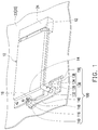
- FIG. 1 is a 3D view illustrating an interface card installed on a main board module before an interface card fixing device presses against the interface card according to an embodiment of the invention.
- a main board module 20 of the present embodiment includes a main board 22 and an interface card fixing device 100.
- the main board 22 includes an interface card slot 24 and a via hole 26 corresponding to the interface card slot 24.
- An interface card 10 may be inserted into the interface card slot 24 and fixed onto the via hole 26 of the main board 22 by the interface card fixing device 100.
- the interface card slot 24 is an NGFF (Next Generation Form Factor) interface card slot 24 (i.e., the interface card slot 24 with an M.2 interface), for example, but the type of the interface card slot 24 is not limited thereto.
- NGFF Next Generation Form Factor
- a plurality of the via holes 26 are provided on the main board 22 (only one of the via holes 26 is schematically illustrated in FIG. 5 ) at nearby places which are 42mm, 60mm, 80mm and 110mm, respectively, away from the interface card slot 24 with the M.2 interface.
- the M.2 interface card of the corresponding length can be fixed to the through hole 26.
- the interface card 10 is an NGFF (Next Generation Form Factor) interface card, for example, but the type of the interface card 10 is not limited thereto.
- the interface card 10 includes a connecting end 12 and a fixing connection 14, where an edge of the fixing end 14 has a semicircular hole 16.
- the connecting end 12 of the interface card 10 is inserted into the interface card slot 24, and the fixing end 14 of the interface card 10 can be fixed to the via hole 26 of the main board 22 through the interface card fixing device 100 quickly, easily and stably. Description regarding the above is provided in detail below.
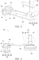
- FIG. 2 to FIG. 4 are schematic views of the interface card fixing device of FIG. 1 in different viewing angles.
- the interface card fixing device 100 includes a base 110, a fixing portion 120, an engaging portion 130, a connecting portion 140 and a handle portion 150.
- the base 110 includes a first surface 112 and a second surface 114 opposite to each other and a protrusion 116 protruding from the first surface 112, and the base 110 has a through hole 118 passing through the first surface 112, the second surface 114 and the protrusion 116 so that the protrusion 116 forms a hollow cylinder.
- the fixing portion 120 extends from the second surface 114 of the base 110 and includes a breach 122 communicating with the through hole 118. More specifically, the fixing portion 120 includes two extending sections 124 (marked in FIG. 3 ) spaced apart by the breach 122, and the two extending sections 124 include engaging bumps 126 outwardly protruding at positions away form each other.
- a size of the first end 136 of the plug 134 is greater than or equal to a size of the through hole 118 of the base 110, and the size of the through hole 118 of the base 110 is greater than a size of the second end 138 of the plug 134.
- the plug 134 has the size of the first end 136 being greater than the size of the second end 138.
- a size L2 of the breach 122 of the fixing portion 120 i.e., a distance between the two extending portions 124) is less than an inner diameter L1 of the through hole 118. Also, in view of FIG.
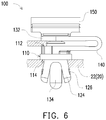
- FIG. 5 and FIG. 6 are local cross-sectional views of the interface card fixing device of FIG. 1 , respectively, before and after pressing against the interface card.
- the fixing portion 120 is detachably disposed through the via hole 26 of the main board 22. More specifically, when the interface card fixing device 100 is disposed in a top-down manner on the main board 22 as shown in FIG. 5 , a portion of the fixing portion 120 is located within the via hole 26 of the main board 22, and another portion (i.e., a portion that is away from the base 110) of the fixing portion 120 passes through the via hole 26 to be located on another side of the main board 22 (i.e., below the main board 22 of FIG. 5 ). As shown in FIG.
- the connecting end 12 of the interface card 10 is inserted into the interface card slot 24, the fixing end 14 of the interface card 10 leans against the first surface 112 of the base 110 and the protrusion 116 is located within the semicircular hole 16 of the interface card 10.
- the interface card fixing device 100 is to be used to fix the interface card 10 to the main board 22, with reference to FIG. 6 , the second end 138 of the plug 134 of the engaging portion 130 of the interface card fixing device 100 sequentially passes through the semicircular hole 16 of the interface card 10 and the through hole 118 of the base 110, enters the breach 122 of the fixing portion 120 and expands the breach 122 of the fixing portion 120.
- the two extending sections 124 of the fixing portion 120 are pushed open by the plug 134 to two sides.
- the two engaging bumps 126 on the two extending sections 124 are farther away from each other so the distance between the two engaging bumps 126 is even greater than the size of the via hole 26 of the main board 22. Accordingly, the fixing portion 120 can be fixed to the main board 22 more stably.
- the size of the first end 136 of the plug 134 is greater than or equal to the size of the through hole 118 of the base 110, and the size of the through hole 118 of the base 110 is greater than the size of the second end 138 of the plug 134.
- the second end 138 of the plug 134 can easily pass through the through hole 118 of the base 110, and the first end 136 of the plug 134 will tightly engage with the wall surface beside the through hole 118 when entering the through hole 118 of the base 110, and fix to the base 110.
- FIG. 7 is a 3D view of the interface card fixing device of FIG. 1 pressing against the interface card.
- the portion of the interface card 10 beside the semicircular hole 16 is located on the first surface 112 of the base 10 and surrounding one half of the protrusion 116, after the plug 134 of the engaging portion 130 is fixed to the base 110, the pressing unit 132 of the engaging portion 130 will press against the portion of the interface card 10 beside semicircular hole 16 to clamp the portion of the interface card 10 beside semicircular hole 16 in between the pressing unit 132 of the engaging portion 130 and the first surface 112 of the base 110, so as to fix the fixing end 14 of the interface card 10.
- the user when intending to install the interface card 10 on the main board 22, the user only needs to insert the fixing portion 120 of the interface card fixing device 100 into the via hole 26 of the main board 22, insert the connecting end 12 of the interface card 10 into the interface card slot 24 of the main board 22, align the semicircular hole 16 on the fixing end 14 of the interface card 10 with the protrusion 116 of the base 110 of the interface card fixing device 100, and lastly, insert the plug 134 of the engaging portion 130 of the interface card fixing device 100 into the through hole 118 of the base 110 until the plug 134 engages with the base 110.
- the interface card 10 is to be detached from the main board 22, it is only required to apply force for pulling up the handle portion 150 so the plug 134 of the engaging portion 130 will then be detached from the base 110 to release engagement of the pressing unit 132 of the engaging portion 130 and the first surface 112 of the base 110 to the fixing portion 14 of the interface card 10.
- the handle portion 150 has a rough surface or a convex mark to increase the friction force, which facilitates the user to pull up the handle portion 150.
- the user can apply force again to pull out the fixing portion 120 from the via hole 26 of the main board 22 so the interface card fixing device 100 can be detached from the main board 22.
- the interface card fixing device 100 of the present embodiment is very easy and simple and can be assembled without the need for additional tools.
- the engaging portion 130 of the interface card fixing device 100 of the present embodiment and the base 110 are fixed at their engagement position, the conventional situation in which skew phenomenon occurs due to overly tight screw locking when fixing the interface card 10 to the main board 22 by locking with screw may be effectively solved.
- the space on the main board 22 is limited.
- connectors or other parts located at an edge of the main board 22 may exist in an extending direction of the interface card slot 24 towards the via hole 26, and thus a distance from the via hole 26 to the connectors or other parts located at the edge of the main board 22 may be quite close. Accordingly, if an extending direction D1 of the connection portion 140 relative to the engaging portion 130 is parallel to an extending direction of the M.2 interface card slot 24 towards the via hole 26, the connecting portion 140 may have interference with the connectors at the edge of the main board 22.
- the handle portion 150 is usually made with a certain size, and the size of the handle portion 150 may even be greater than the size of the connecting portion 140 so it is likely that the handle portion 150 may also have interference with the connectors or other parts at the edge of the main board 22.
- the connecting portion 140 of the interface card fixing device 100 of the present embodiment has the rotatable angle within almost 180 degrees, such that the user can easily choose to arrange the bent connecting portion 140 and the handle portion 150 to suitable positions on the main board 22 without having interference with the parts or the connectors on the main board 22.
- the handle portion 150 may be moved to the suitable position within the rotation range depending on the user's needs.
- the interface card fixing device 100 may be rotated within a range of 150 degrees after the interface card 10 is disposed on the main board 22.
- the rotatable angle of the interface card fixing device 100 is not limited to the above.
- the interface card fixing device of the invention can be detachably disposed through the main board by the fixing portion.
- the connecting portion of the interface card is inserted into the interface card slot, the fixing portion of the interface card leans against the first surface of the interface card fixing device, and the protrusion of the base is located within the semicircular hole of the interface card.
- the semicircular hole of the interface card is aligned with the through hole of the base of the interface card fixing device and the breach of the fixing portion.
- the plug of the interface card fixing device can enter the semicircular hole of the interface card, the through hole of the base and the breach of the fixing portion, and fix to the base.
- the pressing unit of the engaging portion will press against the portion of the interface card beside the semicircular hole to fix the fixing portion of the interface card to the main board.
- the installation can be quite simple and convenient without the need for additional tools.
- the engaging portion of the interface card fixing device and the base are fixed at their engagement position, when the plug of the engaging portion is fixed to the base, the pressing unit can provide a constant and even clamping force to the portion of the interface beside the semicircular hole. As such, the conventional situation in which skew phenomenon occurs due to over tighten locking when fixing the interface card to the main board by locking with screw may be effectively solved.
- the user can freely rotate the interface card fixing device at the position relative to the main board (with the rotatable angle within almost 180 degrees), and the protrusion will be located within the semicircular hole of the interface card as along as the connecting portion has no interference with the parts on the interface card or the main board.
- the user can arrange the position of the connection portion on the main board depending on actual conditions, so as to prevent interference from happening.
Landscapes
- Engineering & Computer Science (AREA)
- Theoretical Computer Science (AREA)
- General Physics & Mathematics (AREA)
- Human Computer Interaction (AREA)
- Physics & Mathematics (AREA)
- General Engineering & Computer Science (AREA)
- Power Engineering (AREA)
- Computer Hardware Design (AREA)
- Microelectronics & Electronic Packaging (AREA)
- Mounting Of Printed Circuit Boards And The Like (AREA)
- Connection Of Plates (AREA)
- Details Of Connecting Devices For Male And Female Coupling (AREA)
- Coupling Device And Connection With Printed Circuit (AREA)
Abstract
Description
- The invention relates to a fixing device and a main board module, and more particularly, to an interface card fixing device and a main board module.
- With increasing demands from users, main boards are provided with a variety of connectors for providing more functionality. Currently, many main boards are disposed with a NGFF (Next Generation Form Factor) slot (i.e., M.2 slot) for inserting an M.2 interface card (e.g., a solid state hard drive (SSD) with M.2 interface). In addition to the M.2 slot, these main boards must also be disposed with a via hole for fixing the M.2 interface card at a corresponding position beside the M.2 slot, such that after one end of the M.2 interface card is inserted into the M.2 slot on the main board, the other end may be fixed to the main board through locking or other methods to increase the stability of the M.2 interface card.
- In terms of locking with screw, because the M.2 interface card is provided with a semicircular hole for positioning on an edge of another end relative to an electrical connecting end, a threaded portion of the screw will be located within the semicircular hole, and a top portion of the screw will press against a portion of the M.2 interface card close to the semicircular hole, so as to fix a relative position of the M.2 interface card to the main board. However, since there is only one half of the top portion of the screw pressing against the portion of the M.2 interface card close to the semicircular hole while the other half of the top potion of the screw is hanging, skew phenomenon are likely to occur on one side when locking with screw is over tighten. Consequently, an uneven force may be applied from screw to the portion of the M.2 interface card close to the semicircular hole. In addition, locking with screw also requires additional tools for assembling and disassembling the M.2 interface card, and is thus less convenient in use.
- The invention provides an interface card fixing device, and a main board module, which includes the above interface card fixing device.
- An interface card fixing device of the invention is adapted to fix an interface card to a main board. The interface card fixing device includes a base, a fixing portion, an engaging portion and a connecting portion. The base includes a first surface, a second surface opposite to the first surface, and a protrusion protruding from the first surface, and the base has a through hole passing through the first surface, the second surface and the protrusion so that the protrusion forms a hollow cylinder. The fixing portion extends from the second surface of the base and includes a breach communicating with the through hole. The engaging portion is adapted to pass through the through hole and the breach, and fix to the base. The connecting portion is connected to the base and the engaging portion.
- In an embodiment of the invention, the interface card fixing device further includes a handle portion, connected to the engaging portion. An included angle between an extending direction of the handle portion relative to the engaging portion and an extending direction of the connecting portion relative to the engaging portion is a right angle, an obtuse angle or an acute angle.
- In an embodiment of the invention, the handle portion has a rough surface or a convex mark.
- In an embodiment of the invention, the engaging portion includes a pressing unit and a plug protruding from the pressing unit. The pressing unit is adapted to press against the interface card. The plug is adapted to enter the breach of the fixing portion. A size of one end of the plug close to the pressing unit is greater than a size of one end of the plug away from the pressing unit.
- In an embodiment of the invention, the plug includes a first end and a second end opposite to each other. The second end is away from the pressing unit and adapted to pass through the through hole, enter and expand the breach. The first end is close to the pressing unit and adapted to engage with the through hole and fix to the base. In an embodiment of the invention, a size of the breach of the fixing portion is less than a size of the through hole.
- A main board module of the invention is adapted to install an interface card. The interface card includes a connecting end and a fixing end. An edge of the fixing portion has a semicircular hole. The main board module includes a main board and an interface card fixing device. The main board includes an interface card slot and a via hole, wherein the connecting end of the interface card is adapted to be inserted into the interface card slot. The interface card fixing device is adapted to fix the fixing end of the interface card to the main board. The interface card fixing device includes a base, a fixing portion, an engaging portion and a connecting portion. The base includes a first surface, a second surface opposite to the first surface, and a protrusion protruding from the first surface, and the base has a through hole passing through the first surface, the second surface and the protrusion so that the protrusion forms a hollow cylinder. The fixing portion is detachably disposed passing through the via hole of the main board. The fixing portion extends from the second surface of the base and includes a breach communicating with the through hole. The engaging portion is adapted to pass through the through hole and the breach, and fix to the base. The connecting portion is connected to the base and the engaging portion. When the interface card is installed on the main board module, the connecting end is inserted into the interface card slot, the fixing portion leans against the first surface of the base so the protrusion is located within the semicircular hole, and the engaging portion engages with the base and presses against the interface card.
- In an embodiment of the invention, the interface card fixing device further includes a handle portion, connected to the engaging portion. An included angle between an extending direction of the handle portion relative to the engaging portion and an extending direction of the connecting portion relative to the engaging portion is a right angle, an obtuse angle or an acute angle.
- In an embodiment of the invention, the handle portion has a rough surface or a convex mark.
- In an embodiment of the invention, the engaging portion includes a pressing unit and a plug protruding from the pressing unit. The pressing unit is adapted to press against the portion of the interface card beside the semicircular hole. The plug is adapted to enter the breach of the fixing portion. A size of one end of the plug close to the pressing unit is greater than a size of one end of the plug away from the pressing unit.
- In an embodiment of the invention, a size of the breach of the fixing portion is less than a size of the through hole.
- Based on the above, the interface card fixing device of the invention can be detachably disposed through the main board by the fixing portion. When the interface card is installed on the main board module, the connecting portion of the interface card is inserted into the interface card slot, the fixing portion of the interface card leans against the first surface of the interface card fixing device, and the protrusion of the base is located within the semicircular hole of the interface card. At this time, the semicircular hole of the interface card is aligned with the through hole of the base of the interface card fixing device and the breach of the fixing portion. The plug of the interface card fixing device can enter the semicircular hole of the interface card, the through hole of the base and the breach of the fixing portion and fix to the base. Also, the pressing unit of the engaging portion will press against the portion of the interface card beside the semicircular hole to fix the fixing portion of the interface card to the main board. In this way, the installation can be quite simple and convenient without the need for additional tools. Further, because the engaging portion of the interface card fixing device and the base are fixed at their engagement position, when the plug of the engaging portion is fixed to the base, the pressing unit can provide a constant and even clamping force to the portion of the interface beside the semicircular hole. As such, the conventional situation in which skew phenomenon occurs due to over tighten locking when fixing the interface card to the main board by locking with screw may be effectively solved. In addition, with the design of the protrusion in from of the hollow cylinder for the interface card fixing device of the invention, the user can freely rotate the interface card fixing device at the position relative to the main board (with the rotatable angle within almost 180 degrees), and the protrusion will be located within the semicircular hole of the interface card as along as the connecting portion has no interference with the parts on the interface card or the main board. As a result, the user can arrange the position of the connection portion on the main board depending on actual conditions, so as to prevent interference from happening.
- To make the above features of the disclosure more comprehensible, several embodiments accompanied with drawings are described in detail as follows.
- The accompanying drawings are included to provide a further understanding of the invention, and are incorporated in and constitute a part of this specification. The drawings illustrate embodiments of the invention and, together with the description, serve to explain the principles of the invention.
-
FIG. 1 is a 3D view illustrating an interface card installed on a main board module before an interface card fixing device presses against the interface card according to an embodiment of the invention. -
FIG. 2 to FIG. 4 are schematic views of the interface card fixing device ofFIG. 1 in different viewing angles. -
FIG. 5 andFIG. 6 are local cross-sectional views of the interface card fixing device ofFIG. 1 , respectively, before and after pressing against the interface card. -
FIG. 7 is a 3D view of the interface card fixing device ofFIG. 1 pressing against the interface card. -
FIG. 8 is a 3D view of the interface card fixing device ofFIG. 1 turned into the other angle relative to the interface card. -
FIG. 9 is a 3D view of the interface card fixing device ofFIG. 1 pressing against the interface card in the other angle. - Reference will now be made in detail to the present preferred embodiments of the invention, examples of which are illustrated in the accompanying drawings. Wherever possible, the same reference numbers are used in the drawings and the description to refer to the same or like parts.
-
FIG. 1 is a 3D view illustrating an interface card installed on a main board module before an interface card fixing device presses against the interface card according to an embodiment of the invention. With reference toFIG. 1 , amain board module 20 of the present embodiment includes amain board 22 and an interfacecard fixing device 100. Themain board 22 includes aninterface card slot 24 and a viahole 26 corresponding to theinterface card slot 24. Aninterface card 10 may be inserted into theinterface card slot 24 and fixed onto the viahole 26 of themain board 22 by the interfacecard fixing device 100. - In the present embodiment, the
interface card slot 24 is an NGFF (Next Generation Form Factor) interface card slot 24 (i.e., theinterface card slot 24 with an M.2 interface), for example, but the type of theinterface card slot 24 is not limited thereto. In general, a plurality of the via holes 26 are provided on the main board 22 (only one of the via holes 26 is schematically illustrated inFIG. 5 ) at nearby places which are 42mm, 60mm, 80mm and 110mm, respectively, away from theinterface card slot 24 with the M.2 interface. As such, in correspondence to a length of the M.2 interface card selected by the user, the M.2 interface card of the corresponding length can be fixed to the throughhole 26. - Similarly, in the present embodiment, the
interface card 10 is an NGFF (Next Generation Form Factor) interface card, for example, but the type of theinterface card 10 is not limited thereto. Theinterface card 10 includes a connectingend 12 and a fixingconnection 14, where an edge of the fixingend 14 has asemicircular hole 16. When theinterface card 10 is installed on themain board module 20, the connectingend 12 of theinterface card 10 is inserted into theinterface card slot 24, and the fixingend 14 of theinterface card 10 can be fixed to the viahole 26 of themain board 22 through the interfacecard fixing device 100 quickly, easily and stably. Description regarding the above is provided in detail below. -
FIG. 2 to FIG. 4 are schematic views of the interface card fixing device ofFIG. 1 in different viewing angles. With reference toFIG. 2 to FIG. 4 , the interfacecard fixing device 100 includes abase 110, a fixingportion 120, an engagingportion 130, a connectingportion 140 and ahandle portion 150. Thebase 110 includes afirst surface 112 and asecond surface 114 opposite to each other and aprotrusion 116 protruding from thefirst surface 112, and thebase 110 has a throughhole 118 passing through thefirst surface 112, thesecond surface 114 and theprotrusion 116 so that theprotrusion 116 forms a hollow cylinder. - The fixing
portion 120 extends from thesecond surface 114 of thebase 110 and includes abreach 122 communicating with the throughhole 118. More specifically, the fixingportion 120 includes two extending sections 124 (marked inFIG. 3 ) spaced apart by thebreach 122, and the two extendingsections 124 include engagingbumps 126 outwardly protruding at positions away form each other. - The engaging
portion 130 includes apressing unit 132 and aplug 134 protruding from thepressing unit 132. Theplug 134 includes afirst end 136 and asecond end 138 opposite to each other. Thefirst end 136 of theplug 134 is close to thepressing unit 132, and thesecond end 138 of theplug 134 is away from thepressing unit 132. The connectingportion 140 is connected to thebase 110 and the engagingportion 130, and thehandle portion 150 is connected to the engagingportion 130. - In the present embodiment, a size of the
first end 136 of theplug 134 is greater than or equal to a size of the throughhole 118 of thebase 110, and the size of the throughhole 118 of thebase 110 is greater than a size of thesecond end 138 of theplug 134. In other words, theplug 134 has the size of thefirst end 136 being greater than the size of thesecond end 138. In addition, as shown inFIG. 4 , in the present embodiment, a size L2 of thebreach 122 of the fixing portion 120 (i.e., a distance between the two extending portions 124) is less than an inner diameter L1 of the throughhole 118. Also, in view ofFIG. 3 , it can be known that an outer diameter of thesecond end 138 of theplug 134 is greater than the size L2 of thebreach 122 of the fixingportion 120. With the size relationship above, in the present embodiment, thesecond end 138 of theplug 134 of the engagingportion 130 is adapted to pass through the throughhole 118, enter and expand thebreach 122, and thefirst end 136 of theplug 134 can engage with a wall surface beside the throughhole 118 of thebase 110 and fix to thebase 110. -
FIG. 5 andFIG. 6 are local cross-sectional views of the interface card fixing device ofFIG. 1 , respectively, before and after pressing against the interface card. With reference toFIG. 5 , the fixingportion 120 is detachably disposed through the viahole 26 of themain board 22. More specifically, when the interfacecard fixing device 100 is disposed in a top-down manner on themain board 22 as shown inFIG. 5 , a portion of the fixingportion 120 is located within the viahole 26 of themain board 22, and another portion (i.e., a portion that is away from the base 110) of the fixingportion 120 passes through the viahole 26 to be located on another side of the main board 22 (i.e., below themain board 22 ofFIG. 5 ). As shown inFIG. 5 , in the present embodiment, because the twoengaging bumps 126 on the two extendingsections 124 of the fixingportion 120 are located below themain board 22, a distance between the twoengaging bumps 126 will be greater than a size of the viahole 26 of themain board 22 so the fixingportion 120 cannot be easily moved up and detached from themain board 22. - Referring to
FIG. 1 andFIG. 5 together, when theinterface card 10 is installed on themain board module 20, the connectingend 12 of theinterface card 10 is inserted into theinterface card slot 24, the fixingend 14 of theinterface card 10 leans against thefirst surface 112 of thebase 110 and theprotrusion 116 is located within thesemicircular hole 16 of theinterface card 10. When the interfacecard fixing device 100 is to be used to fix theinterface card 10 to themain board 22, with reference toFIG. 6 , thesecond end 138 of theplug 134 of the engagingportion 130 of the interfacecard fixing device 100 sequentially passes through thesemicircular hole 16 of theinterface card 10 and the throughhole 118 of thebase 110, enters thebreach 122 of the fixingportion 120 and expands thebreach 122 of the fixingportion 120. At this time, the two extendingsections 124 of the fixingportion 120 are pushed open by theplug 134 to two sides. As can be clearly seen fromFIG. 6 , when theplug 134 is inserted into thebreach 122 of the fixingportion 120, the twoengaging bumps 126 on the two extendingsections 124 are farther away from each other so the distance between the twoengaging bumps 126 is even greater than the size of the viahole 26 of themain board 22. Accordingly, the fixingportion 120 can be fixed to themain board 22 more stably. - Moreover, in the present embodiment, it is given that the size of the
first end 136 of theplug 134 is greater than or equal to the size of the throughhole 118 of thebase 110, and the size of the throughhole 118 of thebase 110 is greater than the size of thesecond end 138 of theplug 134. During the process of fixing theplug 134 of the engagingportion 130 to thebase 110, thesecond end 138 of theplug 134 can easily pass through the throughhole 118 of thebase 110, and thefirst end 136 of theplug 134 will tightly engage with the wall surface beside the throughhole 118 when entering the throughhole 118 of thebase 110, and fix to thebase 110. - In addition,
FIG. 7 is a 3D view of the interface card fixing device ofFIG. 1 pressing against the interface card. Referring toFIG. 6 andFIG. 7 together, because the portion of theinterface card 10 beside thesemicircular hole 16 is located on thefirst surface 112 of thebase 10 and surrounding one half of theprotrusion 116, after theplug 134 of the engagingportion 130 is fixed to thebase 110, thepressing unit 132 of the engagingportion 130 will press against the portion of theinterface card 10 besidesemicircular hole 16 to clamp the portion of theinterface card 10 besidesemicircular hole 16 in between thepressing unit 132 of the engagingportion 130 and thefirst surface 112 of thebase 110, so as to fix the fixingend 14 of theinterface card 10. - In other words, when intending to install the
interface card 10 on themain board 22, the user only needs to insert the fixingportion 120 of the interfacecard fixing device 100 into the viahole 26 of themain board 22, insert the connectingend 12 of theinterface card 10 into theinterface card slot 24 of themain board 22, align thesemicircular hole 16 on the fixingend 14 of theinterface card 10 with theprotrusion 116 of thebase 110 of the interfacecard fixing device 100, and lastly, insert theplug 134 of the engagingportion 130 of the interfacecard fixing device 100 into the throughhole 118 of the base 110 until theplug 134 engages with thebase 110. Similarly, if theinterface card 10 is to be detached from themain board 22, it is only required to apply force for pulling up thehandle portion 150 so theplug 134 of the engagingportion 130 will then be detached from the base 110 to release engagement of thepressing unit 132 of the engagingportion 130 and thefirst surface 112 of the base 110 to the fixingportion 14 of theinterface card 10. - As shown in
FIG. 7 , in the present embodiment, thehandle portion 150 has a rough surface or a convex mark to increase the friction force, which facilitates the user to pull up thehandle portion 150. After theinterface card 10 is removed, the user can apply force again to pull out the fixingportion 120 from the viahole 26 of themain board 22 so the interfacecard fixing device 100 can be detached from themain board 22. In this way, the interfacecard fixing device 100 of the present embodiment is very easy and simple and can be assembled without the need for additional tools. Further, because the engagingportion 130 of the interfacecard fixing device 100 of the present embodiment and the base 110 are fixed at their engagement position, the conventional situation in which skew phenomenon occurs due to overly tight screw locking when fixing theinterface card 10 to themain board 22 by locking with screw may be effectively solved. - It is noted that, the space on the
main board 22 is limited. For instance, connectors or other parts located at an edge of themain board 22 may exist in an extending direction of theinterface card slot 24 towards the viahole 26, and thus a distance from the viahole 26 to the connectors or other parts located at the edge of themain board 22 may be quite close. Accordingly, if an extending direction D1 of theconnection portion 140 relative to the engagingportion 130 is parallel to an extending direction of the M.2interface card slot 24 towards the viahole 26, the connectingportion 140 may have interference with the connectors at the edge of themain board 22. Furthermore, in order to facilitate holding for the user, thehandle portion 150 is usually made with a certain size, and the size of thehandle portion 150 may even be greater than the size of the connectingportion 140 so it is likely that thehandle portion 150 may also have interference with the connectors or other parts at the edge of themain board 22. - In order to reduce the probability for the above interference to occur, the
protrusion 116 of the interfacecard fixing device 100 of the present embodiment is specifically designed in shape of the hollow cylinder. By doing so, the user can freely rotate the interfacecard fixing device 100 at a position relative to the main board 22 (with a rotatable angle within almost 180 degrees), and theprotrusion 116 will be located within thesemicircular hole 16 of theinterface card 10 as long as theconnection portion 140 has no interference with parts on theinterface card 10 or themain board 22.FIG. 8 is a 3D view of the interface card fixing device ofFIG. 1 turned into the other angle relative to the interface card.FIG. 9 is a 3D view of the interface card fixing device ofFIG. 1 pressing against the interface card in the other angle. In view ofFIG. 8 andFIG. 9 , it can be clearly seen that, the connectingportion 140 of the interfacecard fixing device 100 of the present embodiment has the rotatable angle within almost 180 degrees, such that the user can easily choose to arrange the bent connectingportion 140 and thehandle portion 150 to suitable positions on themain board 22 without having interference with the parts or the connectors on themain board 22. As shown inFIG. 9 , in the present embodiment, in the case where theplug 134 of the engagingportion 130 is fixed to thebase 110, thehandle portion 150 may be moved to the suitable position within the rotation range depending on the user's needs. In a more preferable embodiment, the interfacecard fixing device 100 may be rotated within a range of 150 degrees after theinterface card 10 is disposed on themain board 22. Certainly, the rotatable angle of the interfacecard fixing device 100 is not limited to the above. - In addition, as shown in
FIG. 2 andFIG. 7 , in the present embodiment, an included angle between an extending direction D2 of thehandle portion 150 relative to the engagingportion 130 and the extending direction D1 of the connectingportion 140 relative to the engagingportion 130 may be a right angle, an obtuse angle or an acute angle. For instance, the extending direction D2 of thehandle portion 150 relative to the engagingportion 130 is perpendicular to the extending direction D1 of the connectingportion 140 relative to the engagingportion 130, as shown inFIG. 7 . Such configuration can have thehandle portion 150 placed above theinterface card 10 to avoid interference with other parts. Naturally, the angular relationship between the extending direction D2 of thehandle portion 150 relative to the engagingportion 130 and the extending direction D1 of the connectingportion 140 relative to the engagingportion 130 is not limited to the above. In other embodiments, the included angle between the extending direction D2 of thehandle portion 150 relative to the engagingportion 130 and the extending direction D1 of the connectingportion 140 relative to the engagingportion 130 may also be the acute angle or the obtuse angle. - In summary, the interface card fixing device of the invention can be detachably disposed through the main board by the fixing portion. When the interface card is installed on the main board module, the connecting portion of the interface card is inserted into the interface card slot, the fixing portion of the interface card leans against the first surface of the interface card fixing device, and the protrusion of the base is located within the semicircular hole of the interface card. At this time, the semicircular hole of the interface card is aligned with the through hole of the base of the interface card fixing device and the breach of the fixing portion. The plug of the interface card fixing device can enter the semicircular hole of the interface card, the through hole of the base and the breach of the fixing portion, and fix to the base. Also, the pressing unit of the engaging portion will press against the portion of the interface card beside the semicircular hole to fix the fixing portion of the interface card to the main board. In this way, the installation can be quite simple and convenient without the need for additional tools. Further, because the engaging portion of the interface card fixing device and the base are fixed at their engagement position, when the plug of the engaging portion is fixed to the base, the pressing unit can provide a constant and even clamping force to the portion of the interface beside the semicircular hole. As such, the conventional situation in which skew phenomenon occurs due to over tighten locking when fixing the interface card to the main board by locking with screw may be effectively solved. In addition, with the design of the protrusion in from of the hollow cylinder for the interface card fixing device of the invention, the user can freely rotate the interface card fixing device at the position relative to the main board (with the rotatable angle within almost 180 degrees), and the protrusion will be located within the semicircular hole of the interface card as along as the connecting portion has no interference with the parts on the interface card or the main board. As a result, the user can arrange the position of the connection portion on the main board depending on actual conditions, so as to prevent interference from happening.
Claims (12)
- An interface card fixing device (100), adapted to fix an interface card (10) to a main board (22), and the interface card fixing device (100) comprising:a base (110), comprising a first surface (112), a second surface (114) opposite to the first surface (112), and a protrusion (116) protruding from the first surface (112), the base (110) having a through hole (118) passing through the first surface (112), the second surface (114) and the protrusion (116) so that the protrusion (116) forms a hollow cylinder;a fixing portion (120), extending from the second surface (114) of the base (110), and comprising a breach (122) communicating with the through hole (118);an engaging portion (130), adapted to pass through the through hole (118) and the breach (122), and fix to the base (110); anda connection portion (140), connected to the base (110) and the engaging portion (130).
- The interface card fixing device (100) as recited in claim 1, further comprising:a handle portion (150), connected to the engaging portion (130), an included angle between an extending direction of the handle portion (150) relative to the engaging portion (130) and an extending direction of the connecting portion (140) relative to the engaging portion (130) being an acute angle, an obtuse angle or a right angle.
- The interface card fixing device (100) as recited in claim 2, wherein the handle portion (150) has a rough surface or a convex mark.
- The interface card fixing device (100) as recited in claim 1, wherein the engaging portion (130) comprises a pressing unit (132) and a plug (134) protruding from the pressing unit (132), the pressing unit (132) being adapted to press against the interface card (10), the plug (134) being adapted to enter the breach (122) of the fixing portion (120), a size of one end of the plug (134) close to the pressing unit (132) being greater than a size of one end of the plug (134) away from the pressing unit (132).
- The interface card fixing device (100) as recited in claim 4, wherein the plug (134) comprises a first end (136) and a second end (138) opposite to each other, the second end (138) being away from the pressing unit (132) and adapted to pass through the through hole (118), enter and expand the breach (122), the first end (136) being close to the pressing unit (132) and adapted to engage with the through hole (118) and fix to the base (110).
- The interface card fixing device (100) as recited in claim 1, wherein a size of the breach (122) of the fixing portion (120) is smaller than a size of the through hole (118).
- A main board module (20), adapted to install an interface card (10), the interface card (10) comprising a connecting end (12) and a fixing end (14), an edge of the fixing end (14) having a semicircular hole (16), the main board module (20) comprising:a main board (22), comprising an interface card slot (24) and a via hole (26), wherein the connecting end (12) of the interface card (10) is adapted to be inserted into the interface card slot (24); andan interface card fixing device (100), adapted to fix the fixing end (14) of the interface card (10) to the main board (22), the interface card fixing device (100) comprising:a base (110), comprising a first surface (112), a second surface (114) opposite to each other and a protrusion (116) protruding from the first surface (112), the base (110) having a through hole (118) passing through the first surface (112), the second surface (114) and the protrusion (116) so that the protrusion (116) forms a hollow cylinder;a fixing portion (120), detachably disposed passing through into the via hole (26) of the main board (22), the fixing portion (120) extending from the second surface (114) of the base (110) and comprising a breach (122) communicating with the through hole (118);an engaging portion (130), adapted to pass through the through hole (118) and the breach (122), and fix to the base (110); anda connecting portion (140), connected to the base (110) and the engaging portion (130), whereinwhen the interface card (10) is installed on the main board module (20), the connecting end (12) is inserted into the interface card slot (24), the fixing portion (14) leans against the first surface (112) of the base (110), the protrusion (116) is located within the semicircular hole (16), and the engaging portion (130) engages with the base (110) and presses against the interface card (10).
- The main board module (20) as recited in claim 7, further comprising:a handle portion (150), connected to the engaging portion (130), an included angle between an extending direction of the handle portion (150) relative to the engaging portion (130) and an extending direction of the connecting portion (140) relative to the engaging portion (130) being an acute angle, an obtuse angle or a right angle.
- The main board module (20) as recited in claim 8, wherein the handle portion (150) has a rough surface or a convex mark.
- The main board module (20) as recited in claim 7, wherein the engaging portion (130) comprises a pressing unit (132) and a plug (134) protruding from the pressing unit (132), the pressing unit (132) being adapted to press against a portion of the interface card (10) beside the semicircular hole (16), the plug (134) being adapted to enter the breach (122) of the fixing portion (120), a size of one end of the plug (134) close to the pressing unit (132) being greater than a size of one end of the plug (134) away from the pressing unit (132).
- The main board module (20) as recited in claim 10, wherein the plug (134) comprises a first end (136) and a second end (138) opposite to each other, the second end (138) being away from the pressing unit (132) and adapted to pass through the through hole (118), enter and expand the breach (122), the first end (136) being close to the pressing unit (132) and adapted to engage with the through hole (118) and fix to the base (110).
- The main board module (20) as recited in claim 7, wherein a size of the breach (122) of the fixing portion (120) is smaller than a size of the through hole (118).
Applications Claiming Priority (1)
| Application Number | Priority Date | Filing Date | Title |
|---|---|---|---|
| TW105132312A TWI619421B (en) | 2016-10-06 | 2016-10-06 | Interface card fixing device and main board module |
Publications (2)
| Publication Number | Publication Date |
|---|---|
| EP3306440A1 true EP3306440A1 (en) | 2018-04-11 |
| EP3306440B1 EP3306440B1 (en) | 2019-01-23 |
Family
ID=59895172
Family Applications (1)
| Application Number | Title | Priority Date | Filing Date |
|---|---|---|---|
| EP17191359.3A Active EP3306440B1 (en) | 2016-10-06 | 2017-09-15 | Interface card fixing device and main board module |
Country Status (4)
| Country | Link |
|---|---|
| US (1) | US20180102600A1 (en) |
| EP (1) | EP3306440B1 (en) |
| CN (1) | CN107918461B (en) |
| TW (1) | TWI619421B (en) |
Cited By (1)
| Publication number | Priority date | Publication date | Assignee | Title |
|---|---|---|---|---|
| US20250120032A1 (en) * | 2023-10-06 | 2025-04-10 | Wistron Corp. | Fixing frame and electronic device |
Families Citing this family (9)
| Publication number | Priority date | Publication date | Assignee | Title |
|---|---|---|---|---|
| JP7022385B2 (en) * | 2018-03-16 | 2022-02-18 | 株式会社リコー | Display operation unit and image forming device |
| US11226658B2 (en) * | 2018-06-25 | 2022-01-18 | Dell Products L.P. | Apparatus and methods for mounting information handling system hardware components |
| US10720722B2 (en) * | 2018-09-14 | 2020-07-21 | Quanta Computer Inc. | Electronics connector for facilitating treatment |
| CN111417274B (en) * | 2019-01-04 | 2022-01-14 | 神讯电脑(昆山)有限公司 | Electronic device with assembling and positioning functions |
| CN115799929A (en) * | 2021-09-10 | 2023-03-14 | 英业达科技有限公司 | Communication module adapter and electronic device |
| US12374829B2 (en) * | 2021-12-08 | 2025-07-29 | Giga-Byte Technology Co., Ltd. | Circuit board module and release component |
| CN115802684A (en) * | 2022-12-26 | 2023-03-14 | 环荣电子(惠州)有限公司 | A wireless module antenna fixing device |
| TWI847594B (en) * | 2023-03-14 | 2024-07-01 | 英業達股份有限公司 | Mounting structure and server |
| TWI875465B (en) * | 2024-02-05 | 2025-03-01 | 富世達股份有限公司 | Electronic card retaining device |
Citations (5)
| Publication number | Priority date | Publication date | Assignee | Title |
|---|---|---|---|---|
| US2542144A (en) * | 1945-01-01 | 1951-02-20 | Shellmar Products Corp | Blind rivet |
| US6112911A (en) * | 1998-02-10 | 2000-09-05 | Molex Incorporated | Support assembly for board-mounted electrical appliance |
| US20030001467A1 (en) * | 2001-06-29 | 2003-01-02 | Daniel Shyr | Retainer for retaining interface isolating pieces |
| US7335032B1 (en) * | 2006-10-18 | 2008-02-26 | T-Conn Precision Corp. | Interface card securing device including grounding element |
| US20080227326A1 (en) * | 2007-03-15 | 2008-09-18 | T-Conn Precision Corp. | Mounting pin and plughole arrangement |
Family Cites Families (12)
| Publication number | Priority date | Publication date | Assignee | Title |
|---|---|---|---|---|
| KR100430879B1 (en) * | 2002-02-06 | 2004-05-17 | 남성훈 | Elastic collet for pcb mounting jig and pcb mounted jig assembly |
| CN200944209Y (en) * | 2006-02-07 | 2007-09-05 | 番禺得意精密电子工业有限公司 | Buckling device |
| TW200741412A (en) * | 2006-04-25 | 2007-11-01 | T Conn Prec Corp | Fastening apparatus of interface card |
| TW200816911A (en) * | 2006-09-19 | 2008-04-01 | T Conn Prec Corp | Improvement in grounding structure of a fixing device for interface cards |
| CN101201664B (en) * | 2006-12-11 | 2011-06-29 | 英业达股份有限公司 | adapter card holder |
| CN200990449Y (en) * | 2006-12-15 | 2007-12-12 | 番禺得意精密电子工业有限公司 | Fastening device |
| TW200847894A (en) * | 2007-05-30 | 2008-12-01 | T Conn Prec Corp | Improved structure of interface card fixation device |
| CN201465017U (en) * | 2009-06-29 | 2010-05-12 | 研祥智能科技股份有限公司 | Adjustable moving pressure foot of board card |
| CN201515578U (en) * | 2009-09-17 | 2010-06-23 | 番禺得意精密电子工业有限公司 | Buckling and holding device |
| CN103176560B (en) * | 2011-12-20 | 2016-03-30 | 英业达股份有限公司 | Adapter card fixing device and combined structure of the adapter card fixing device and the chassis |
| WO2015047299A1 (en) * | 2013-09-27 | 2015-04-02 | Hewlett-Packard Development Company, L.P. | Grips to retain fasteners for expansion cards |
| US9952634B2 (en) * | 2016-03-28 | 2018-04-24 | Lenovo (Singapore) Pte. Ltd. | Interfacing with multiple components connected to a printed circuit board |
-
2016
- 2016-10-06 TW TW105132312A patent/TWI619421B/en active
- 2016-10-18 CN CN201610905422.2A patent/CN107918461B/en active Active
-
2017
- 2017-08-11 US US15/674,521 patent/US20180102600A1/en not_active Abandoned
- 2017-09-15 EP EP17191359.3A patent/EP3306440B1/en active Active
Patent Citations (5)
| Publication number | Priority date | Publication date | Assignee | Title |
|---|---|---|---|---|
| US2542144A (en) * | 1945-01-01 | 1951-02-20 | Shellmar Products Corp | Blind rivet |
| US6112911A (en) * | 1998-02-10 | 2000-09-05 | Molex Incorporated | Support assembly for board-mounted electrical appliance |
| US20030001467A1 (en) * | 2001-06-29 | 2003-01-02 | Daniel Shyr | Retainer for retaining interface isolating pieces |
| US7335032B1 (en) * | 2006-10-18 | 2008-02-26 | T-Conn Precision Corp. | Interface card securing device including grounding element |
| US20080227326A1 (en) * | 2007-03-15 | 2008-09-18 | T-Conn Precision Corp. | Mounting pin and plughole arrangement |
Cited By (1)
| Publication number | Priority date | Publication date | Assignee | Title |
|---|---|---|---|---|
| US20250120032A1 (en) * | 2023-10-06 | 2025-04-10 | Wistron Corp. | Fixing frame and electronic device |
Also Published As
| Publication number | Publication date |
|---|---|
| TW201815252A (en) | 2018-04-16 |
| CN107918461A (en) | 2018-04-17 |
| EP3306440B1 (en) | 2019-01-23 |
| TWI619421B (en) | 2018-03-21 |
| US20180102600A1 (en) | 2018-04-12 |
| CN107918461B (en) | 2020-12-22 |
Similar Documents
| Publication | Publication Date | Title |
|---|---|---|
| EP3306440B1 (en) | Interface card fixing device and main board module | |
| US8961214B2 (en) | Connecting device and combination of the same and expansion card | |
| US9362672B1 (en) | Lockable socket | |
| US8526192B2 (en) | Boss for securing pair of mainboards | |
| CN106647956B (en) | Connecting assembly | |
| US20110122569A1 (en) | Expansion card retention assembly and computer incorporating the same | |
| WO2017135339A1 (en) | Clip, clamp assembly, and mounting structure | |
| CN105794328A (en) | Clamps to hold fasteners for expansion cards | |
| US20160022030A1 (en) | Desktop receptacle with flip cover | |
| CN107248381A (en) | A kind of LED screen splicing construction and LED screen | |
| US20110154773A1 (en) | Recessed mount with stowed clamps | |
| CN105579762A (en) | quick mount connector | |
| KR20210080577A (en) | Display Screen Stands and Mounting Systems | |
| CN106033236A (en) | Chassis device | |
| TW201239183A (en) | Locking device and electronic apparatus using the same | |
| JP5364910B2 (en) | Power line marking device | |
| JP2011072164A (en) | Cable holding mechanism | |
| US20170117693A1 (en) | A cable clamp | |
| US20150311644A1 (en) | Plugging and unplugging module case | |
| JP2011096891A (en) | Apparatus fixture and rack system | |
| CN108432062B (en) | Clamp cup for securing electrical connectors with first and second mating structures | |
| JP6533956B2 (en) | Cable drawing apparatus and pole using the same | |
| CN110165445B (en) | Connector with integrated guide structure | |
| US20160279745A1 (en) | Installation Equipment and Assembling and Disassembling Method Thereof | |
| US9608376B1 (en) | Electrical connection device |
Legal Events
| Date | Code | Title | Description |
|---|---|---|---|
| PUAI | Public reference made under article 153(3) epc to a published international application that has entered the european phase |
Free format text: ORIGINAL CODE: 0009012 |
|
| STAA | Information on the status of an ep patent application or granted ep patent |
Free format text: STATUS: THE APPLICATION HAS BEEN PUBLISHED |
|
| AK | Designated contracting states |
Kind code of ref document: A1 Designated state(s): AL AT BE BG CH CY CZ DE DK EE ES FI FR GB GR HR HU IE IS IT LI LT LU LV MC MK MT NL NO PL PT RO RS SE SI SK SM TR |
|
| AX | Request for extension of the european patent |
Extension state: BA ME |
|
| STAA | Information on the status of an ep patent application or granted ep patent |
Free format text: STATUS: REQUEST FOR EXAMINATION WAS MADE |
|
| 17P | Request for examination filed |
Effective date: 20180509 |
|
| RBV | Designated contracting states (corrected) |
Designated state(s): AL AT BE BG CH CY CZ DE DK EE ES FI FR GB GR HR HU IE IS IT LI LT LU LV MC MK MT NL NO PL PT RO RS SE SI SK SM TR |
|
| GRAP | Despatch of communication of intention to grant a patent |
Free format text: ORIGINAL CODE: EPIDOSNIGR1 |
|
| STAA | Information on the status of an ep patent application or granted ep patent |
Free format text: STATUS: GRANT OF PATENT IS INTENDED |
|
| RIC1 | Information provided on ipc code assigned before grant |
Ipc: G06F 1/18 20060101AFI20180629BHEP |
|
| INTG | Intention to grant announced |
Effective date: 20180726 |
|
| GRAS | Grant fee paid |
Free format text: ORIGINAL CODE: EPIDOSNIGR3 |
|
| GRAA | (expected) grant |
Free format text: ORIGINAL CODE: 0009210 |
|
| STAA | Information on the status of an ep patent application or granted ep patent |
Free format text: STATUS: THE PATENT HAS BEEN GRANTED |
|
| AK | Designated contracting states |
Kind code of ref document: B1 Designated state(s): AL AT BE BG CH CY CZ DE DK EE ES FI FR GB GR HR HU IE IS IT LI LT LU LV MC MK MT NL NO PL PT RO RS SE SI SK SM TR |
|
| REG | Reference to a national code |
Ref country code: GB Ref legal event code: FG4D |
|
| REG | Reference to a national code |
Ref country code: CH Ref legal event code: EP |
|
| REG | Reference to a national code |
Ref country code: AT Ref legal event code: REF Ref document number: 1091958 Country of ref document: AT Kind code of ref document: T Effective date: 20190215 |
|
| REG | Reference to a national code |
Ref country code: IE Ref legal event code: FG4D |
|
| REG | Reference to a national code |
Ref country code: DE Ref legal event code: R096 Ref document number: 602017001912 Country of ref document: DE |
|
| REG | Reference to a national code |
Ref country code: NL Ref legal event code: MP Effective date: 20190123 |
|
| PG25 | Lapsed in a contracting state [announced via postgrant information from national office to epo] |
Ref country code: NL Free format text: LAPSE BECAUSE OF FAILURE TO SUBMIT A TRANSLATION OF THE DESCRIPTION OR TO PAY THE FEE WITHIN THE PRESCRIBED TIME-LIMIT Effective date: 20190123 |
|
| PG25 | Lapsed in a contracting state [announced via postgrant information from national office to epo] |
Ref country code: SE Free format text: LAPSE BECAUSE OF FAILURE TO SUBMIT A TRANSLATION OF THE DESCRIPTION OR TO PAY THE FEE WITHIN THE PRESCRIBED TIME-LIMIT Effective date: 20190123 Ref country code: PT Free format text: LAPSE BECAUSE OF FAILURE TO SUBMIT A TRANSLATION OF THE DESCRIPTION OR TO PAY THE FEE WITHIN THE PRESCRIBED TIME-LIMIT Effective date: 20190523 Ref country code: NO Free format text: LAPSE BECAUSE OF FAILURE TO SUBMIT A TRANSLATION OF THE DESCRIPTION OR TO PAY THE FEE WITHIN THE PRESCRIBED TIME-LIMIT Effective date: 20190423 Ref country code: PL Free format text: LAPSE BECAUSE OF FAILURE TO SUBMIT A TRANSLATION OF THE DESCRIPTION OR TO PAY THE FEE WITHIN THE PRESCRIBED TIME-LIMIT Effective date: 20190123 Ref country code: ES Free format text: LAPSE BECAUSE OF FAILURE TO SUBMIT A TRANSLATION OF THE DESCRIPTION OR TO PAY THE FEE WITHIN THE PRESCRIBED TIME-LIMIT Effective date: 20190123 Ref country code: LT Free format text: LAPSE BECAUSE OF FAILURE TO SUBMIT A TRANSLATION OF THE DESCRIPTION OR TO PAY THE FEE WITHIN THE PRESCRIBED TIME-LIMIT Effective date: 20190123 Ref country code: FI Free format text: LAPSE BECAUSE OF FAILURE TO SUBMIT A TRANSLATION OF THE DESCRIPTION OR TO PAY THE FEE WITHIN THE PRESCRIBED TIME-LIMIT Effective date: 20190123 |
|
| REG | Reference to a national code |
Ref country code: AT Ref legal event code: MK05 Ref document number: 1091958 Country of ref document: AT Kind code of ref document: T Effective date: 20190123 |
|
| PG25 | Lapsed in a contracting state [announced via postgrant information from national office to epo] |
Ref country code: HR Free format text: LAPSE BECAUSE OF FAILURE TO SUBMIT A TRANSLATION OF THE DESCRIPTION OR TO PAY THE FEE WITHIN THE PRESCRIBED TIME-LIMIT Effective date: 20190123 Ref country code: LV Free format text: LAPSE BECAUSE OF FAILURE TO SUBMIT A TRANSLATION OF THE DESCRIPTION OR TO PAY THE FEE WITHIN THE PRESCRIBED TIME-LIMIT Effective date: 20190123 Ref country code: BG Free format text: LAPSE BECAUSE OF FAILURE TO SUBMIT A TRANSLATION OF THE DESCRIPTION OR TO PAY THE FEE WITHIN THE PRESCRIBED TIME-LIMIT Effective date: 20190423 Ref country code: RS Free format text: LAPSE BECAUSE OF FAILURE TO SUBMIT A TRANSLATION OF THE DESCRIPTION OR TO PAY THE FEE WITHIN THE PRESCRIBED TIME-LIMIT Effective date: 20190123 Ref country code: IS Free format text: LAPSE BECAUSE OF FAILURE TO SUBMIT A TRANSLATION OF THE DESCRIPTION OR TO PAY THE FEE WITHIN THE PRESCRIBED TIME-LIMIT Effective date: 20190523 Ref country code: GR Free format text: LAPSE BECAUSE OF FAILURE TO SUBMIT A TRANSLATION OF THE DESCRIPTION OR TO PAY THE FEE WITHIN THE PRESCRIBED TIME-LIMIT Effective date: 20190424 |
|
| REG | Reference to a national code |
Ref country code: DE Ref legal event code: R097 Ref document number: 602017001912 Country of ref document: DE |
|
| PG25 | Lapsed in a contracting state [announced via postgrant information from national office to epo] |
Ref country code: EE Free format text: LAPSE BECAUSE OF FAILURE TO SUBMIT A TRANSLATION OF THE DESCRIPTION OR TO PAY THE FEE WITHIN THE PRESCRIBED TIME-LIMIT Effective date: 20190123 Ref country code: DK Free format text: LAPSE BECAUSE OF FAILURE TO SUBMIT A TRANSLATION OF THE DESCRIPTION OR TO PAY THE FEE WITHIN THE PRESCRIBED TIME-LIMIT Effective date: 20190123 Ref country code: SK Free format text: LAPSE BECAUSE OF FAILURE TO SUBMIT A TRANSLATION OF THE DESCRIPTION OR TO PAY THE FEE WITHIN THE PRESCRIBED TIME-LIMIT Effective date: 20190123 Ref country code: AL Free format text: LAPSE BECAUSE OF FAILURE TO SUBMIT A TRANSLATION OF THE DESCRIPTION OR TO PAY THE FEE WITHIN THE PRESCRIBED TIME-LIMIT Effective date: 20190123 Ref country code: CZ Free format text: LAPSE BECAUSE OF FAILURE TO SUBMIT A TRANSLATION OF THE DESCRIPTION OR TO PAY THE FEE WITHIN THE PRESCRIBED TIME-LIMIT Effective date: 20190123 Ref country code: RO Free format text: LAPSE BECAUSE OF FAILURE TO SUBMIT A TRANSLATION OF THE DESCRIPTION OR TO PAY THE FEE WITHIN THE PRESCRIBED TIME-LIMIT Effective date: 20190123 Ref country code: IT Free format text: LAPSE BECAUSE OF FAILURE TO SUBMIT A TRANSLATION OF THE DESCRIPTION OR TO PAY THE FEE WITHIN THE PRESCRIBED TIME-LIMIT Effective date: 20190123 |
|
| PG25 | Lapsed in a contracting state [announced via postgrant information from national office to epo] |
Ref country code: SM Free format text: LAPSE BECAUSE OF FAILURE TO SUBMIT A TRANSLATION OF THE DESCRIPTION OR TO PAY THE FEE WITHIN THE PRESCRIBED TIME-LIMIT Effective date: 20190123 |
|
| PLBE | No opposition filed within time limit |
Free format text: ORIGINAL CODE: 0009261 |
|
| STAA | Information on the status of an ep patent application or granted ep patent |
Free format text: STATUS: NO OPPOSITION FILED WITHIN TIME LIMIT |
|
| PG25 | Lapsed in a contracting state [announced via postgrant information from national office to epo] |
Ref country code: AT Free format text: LAPSE BECAUSE OF FAILURE TO SUBMIT A TRANSLATION OF THE DESCRIPTION OR TO PAY THE FEE WITHIN THE PRESCRIBED TIME-LIMIT Effective date: 20190123 |
|
| 26N | No opposition filed |
Effective date: 20191024 |
|
| PG25 | Lapsed in a contracting state [announced via postgrant information from national office to epo] |
Ref country code: SI Free format text: LAPSE BECAUSE OF FAILURE TO SUBMIT A TRANSLATION OF THE DESCRIPTION OR TO PAY THE FEE WITHIN THE PRESCRIBED TIME-LIMIT Effective date: 20190123 |
|
| PG25 | Lapsed in a contracting state [announced via postgrant information from national office to epo] |
Ref country code: TR Free format text: LAPSE BECAUSE OF FAILURE TO SUBMIT A TRANSLATION OF THE DESCRIPTION OR TO PAY THE FEE WITHIN THE PRESCRIBED TIME-LIMIT Effective date: 20190123 |
|
| PG25 | Lapsed in a contracting state [announced via postgrant information from national office to epo] |
Ref country code: MC Free format text: LAPSE BECAUSE OF FAILURE TO SUBMIT A TRANSLATION OF THE DESCRIPTION OR TO PAY THE FEE WITHIN THE PRESCRIBED TIME-LIMIT Effective date: 20190123 |
|
| PG25 | Lapsed in a contracting state [announced via postgrant information from national office to epo] |
Ref country code: IE Free format text: LAPSE BECAUSE OF NON-PAYMENT OF DUE FEES Effective date: 20190915 Ref country code: LU Free format text: LAPSE BECAUSE OF NON-PAYMENT OF DUE FEES Effective date: 20190915 |
|
| REG | Reference to a national code |
Ref country code: BE Ref legal event code: MM Effective date: 20190930 |
|
| PG25 | Lapsed in a contracting state [announced via postgrant information from national office to epo] |
Ref country code: BE Free format text: LAPSE BECAUSE OF NON-PAYMENT OF DUE FEES Effective date: 20190930 |
|
| REG | Reference to a national code |
Ref country code: CH Ref legal event code: PL |
|
| PG25 | Lapsed in a contracting state [announced via postgrant information from national office to epo] |
Ref country code: CY Free format text: LAPSE BECAUSE OF FAILURE TO SUBMIT A TRANSLATION OF THE DESCRIPTION OR TO PAY THE FEE WITHIN THE PRESCRIBED TIME-LIMIT Effective date: 20190123 |
|
| PG25 | Lapsed in a contracting state [announced via postgrant information from national office to epo] |
Ref country code: MT Free format text: LAPSE BECAUSE OF FAILURE TO SUBMIT A TRANSLATION OF THE DESCRIPTION OR TO PAY THE FEE WITHIN THE PRESCRIBED TIME-LIMIT Effective date: 20190123 Ref country code: HU Free format text: LAPSE BECAUSE OF FAILURE TO SUBMIT A TRANSLATION OF THE DESCRIPTION OR TO PAY THE FEE WITHIN THE PRESCRIBED TIME-LIMIT; INVALID AB INITIO Effective date: 20170915 |
|
| PG25 | Lapsed in a contracting state [announced via postgrant information from national office to epo] |
Ref country code: LI Free format text: LAPSE BECAUSE OF NON-PAYMENT OF DUE FEES Effective date: 20200930 Ref country code: CH Free format text: LAPSE BECAUSE OF NON-PAYMENT OF DUE FEES Effective date: 20200930 |
|
| PG25 | Lapsed in a contracting state [announced via postgrant information from national office to epo] |
Ref country code: MK Free format text: LAPSE BECAUSE OF FAILURE TO SUBMIT A TRANSLATION OF THE DESCRIPTION OR TO PAY THE FEE WITHIN THE PRESCRIBED TIME-LIMIT Effective date: 20190123 |
|
| PGFP | Annual fee paid to national office [announced via postgrant information from national office to epo] |
Ref country code: DE Payment date: 20250702 Year of fee payment: 9 |
|
| PGFP | Annual fee paid to national office [announced via postgrant information from national office to epo] |
Ref country code: GB Payment date: 20250703 Year of fee payment: 9 |
|
| PGFP | Annual fee paid to national office [announced via postgrant information from national office to epo] |
Ref country code: FR Payment date: 20250708 Year of fee payment: 9 |